COMPUTER DATA LINES
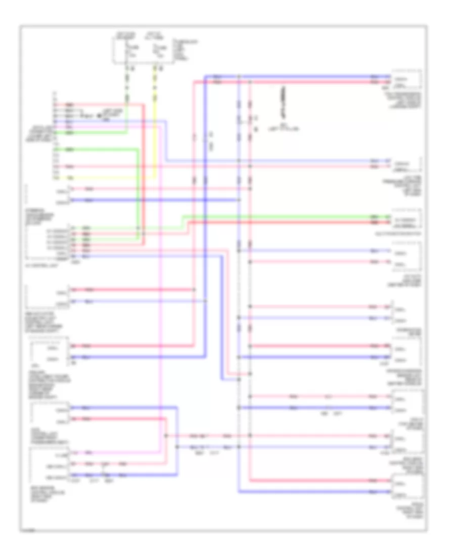
Computer Data Lines Wiring Diagram for Nissan GT-R Black Edition 2014
List of elements for Computer Data Lines Wiring Diagram for Nissan GT-R Black Edition 2014:
- (left side of dash) m55
- A/c auto amplifier (center of dash)
- Abs actuator & electric unit (control unit) (left rear corner of engine compt)
- Air bag diagnosis sensor unit (rear of center console)
- Av comm(h)
- Av comm(l)
- Av control unit
- Awd control unit (under front passenger's seat)
- B201
- B31 (left "c" pillar)
- B45
- Bcm (body control module) (right end of dash)
- Can i/f (top center of dash)
- Can+(h)
- Can+h
- Can-(l)
- Can-h
- Can-l
- Combination meter
- Cpu
- Data link connector (lower left side of dash)
- E-sus control unit (right end of dash)
- E104
- Ecm (engine control module) (right end of dash)
- Fuse 10a
- Fuse block (j/b) (left kick panel)
- Hot at all times
- Hot in on or start
- Ipdm e/r (intelligent power distribution module engine room) (right rear corner of engine compt)
- K line
- Low tire pressure warning control unit (left end of dash)
- M107
- M117
- M122
- M157
- M203
- M271
- M92
- Multi-function switch
- Pnk
- Red
- Shield
- Steering angle sensor (on steering column)
- Tcm (transmission control module) (left side of luggage compt)
- Veh can-h1
- Veh can-l1
 English