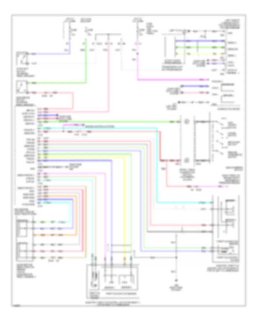
CRUISE CONTROL
Cruise Control Wiring Diagram for Nissan GT-R Black Edition 2014
List of elements for Cruise Control Wiring Diagram for Nissan GT-R Black Edition 2014:
- (left "c" pillar) b31
- (left side of luggage compt) tcm (transmission control module)
- (right front of engine compt) refrigerant pressure sensor
- (right side of dash) m95
- Accelerator pedal position sensor (top of accelerator pedal assembly)
- Aps1
- Aps2
- Ascd brake switch (on brake pedal bracket)
- Ascd steering switch
- Ascd sw
- Avcc2-aps2
- B45
- B47
- Brk sw
- Can-h
- Can-l
- Cancel switch
- Close
- Combination meter
- Computer data lines system
- Cruise ind
- E103
- E106
- Ecm (engine control module) (right end of dash)
- Electric throttle control actuator (bank 1) (top of right cylinder bank)
- Electric throttle control actuator (bank 2) (top of left cylinder bank)
- Engine controls system
- F101
- F102
- F103
- Fuse 10a
- Fuse block (j/b) (left kick panel)
- Gnd
- Gnda-aps1
- Gnda-aps2
- Hot at all times
- Hot in on or start
- M107
- M11 (left end of dash)
- M116
- M303
- M36
- M95 (right side of dash)
- Main (on/off) switch
- Mtr cls
- Mtr-b2
- Mtr1-b1
- Mtr2-b1
- Nca
- Open
- Output shaft speed sensor
- Pnk
- Pwr sply
- Red
- Resume/ accelerate switch
- Sens (+)
- Sens (-)
- Sens gnd
- Sens pwr sply
- Sens sig
- Sensor 1
- Sensor 2
- Set ind
- Set/coast switch
- Spiral cable (combination switch) (in steering column)
- Stop lp sw
- Stop lp sw sig
- Stoplight switch (on brake pedal bracket)
- Throttle control motor
- Throttle position sensor
- Tps1-b1
- Tps1-b2
- Tps2-b1
- Tps2-b2
- Transmission unit (on transmission)
- Vehcan-h1
- Vehcan-l1
 English