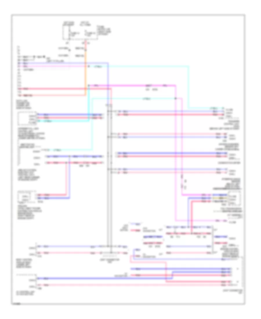
COMPUTER DATA LINES
Computer Data Lines Wiring Diagram for Nissan Xterra PRO-4X 2013
List of elements for Computer Data Lines Wiring Diagram for Nissan Xterra PRO-4X 2013:
- 48g
- 51g
- 52g
- 8p m4
- A/t
- A/t assembly (a/t)
- Abs actuator & electric unit (control unit) (left rear corner of engine compt)
- Abs/tcs/vdc control unit
- Air bag diagnosis sensor unit (under console box)
- Av control unit (w/ navigation)
- Body control module (bcm) (under left side of dash)
- Can-h
- Can-l
- Combination meter
- Cpu
- Data link connector (under left side of dash)
- Diag-k
- Differential lock control unit (w/ electronic locking rear differential) (under center of dash)
- E122
- E152
- E16
- E26
- Engine control module (ecm) (right rear of engine compt)
- F14
- F32
- F502
- Fuse 12 10a
- Fuse 19 10a
- Fuse block (j/b) (right side of dash)
- Hot at all times
- Hot in on or start
- Ipdm e/r (intelligent power distribution module engine room) (right rear of engine compt)
- Joint connector m01
- Joint connector m02
- K-line
- M/t
- M152
- M18
- M31
- M31 e152
- M35
- M57 (left "a" pillar)
- M91
- M96
- Pnk
- Steering angle sensor (below left side of dash, near steering column)
- Tcm (transmission control module)
- Transfer control unit (4wd) (behind left side of dash)
- W/ navigation
- W/o navi- gation
- W/o navigation
 English