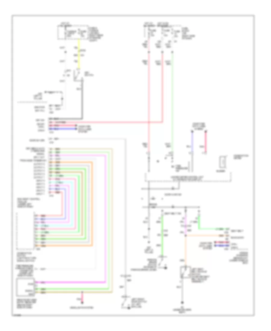
WARNING SYSTEMS
Warning Systems Wiring Diagram for Nissan Xterra PRO-4X 2013
List of elements for Warning Systems Wiring Diagram for Nissan Xterra PRO-4X 2013:
- 15p
- 55g m31
- 61j
- 68j
- 70j
- Air bag diagnosis sensor unit (under console box)
- B69
- B7 (under driver's seat)
- Bat (f/l)
- Bcm (body control module) (under left side of dash)
- Brake ind
- Buckle sw
- Buzzer
- Can-h
- Can-l
- Combination meter
- Combination switch (lighting & turn signal switch)
- Computer data lines system
- Door ajar ind
- Door sw (dr)
- E10
- E152
- Fuse & fusible link box (right rear of engine compt)
- Fuse 10a
- Fuse block (j/b) (right side of dash)
- Fusible link g 50a
- Gnd
- Gnd pwr
- Headlights system
- Hot at all times
- Hot in on or start
- Ign sw
- Input 1
- Input 2
- Input 3
- Input 4
- Input 5
- Key sw
- Key switch
- Keyless & auto lt sens gnd
- Left front door switch (at left b-pillar)
- Left seat belt buckle switch (in driver seat belt buckle assembly)
- M18
- M19
- M20
- M28
- M35
- M40
- M57 (left a- pillar)
- Output 1
- Output 2
- Output 3
- Output 4
- Output 5
- Parking brake switch (on base of parking brake lever)
- Pnk
- Pwr
- Red
- Remote keyless entry receiver (behind right side of dash)
- Seat belt
- Seat belt ind
- Signal
- Sply out
- Tire pressure ind
- Tire pressure warning check connector (under left side of dash)
- Tpms mode trigger sw
- Unified meter control unit (w/ information display)
 English