COMPUTER DATA LINES
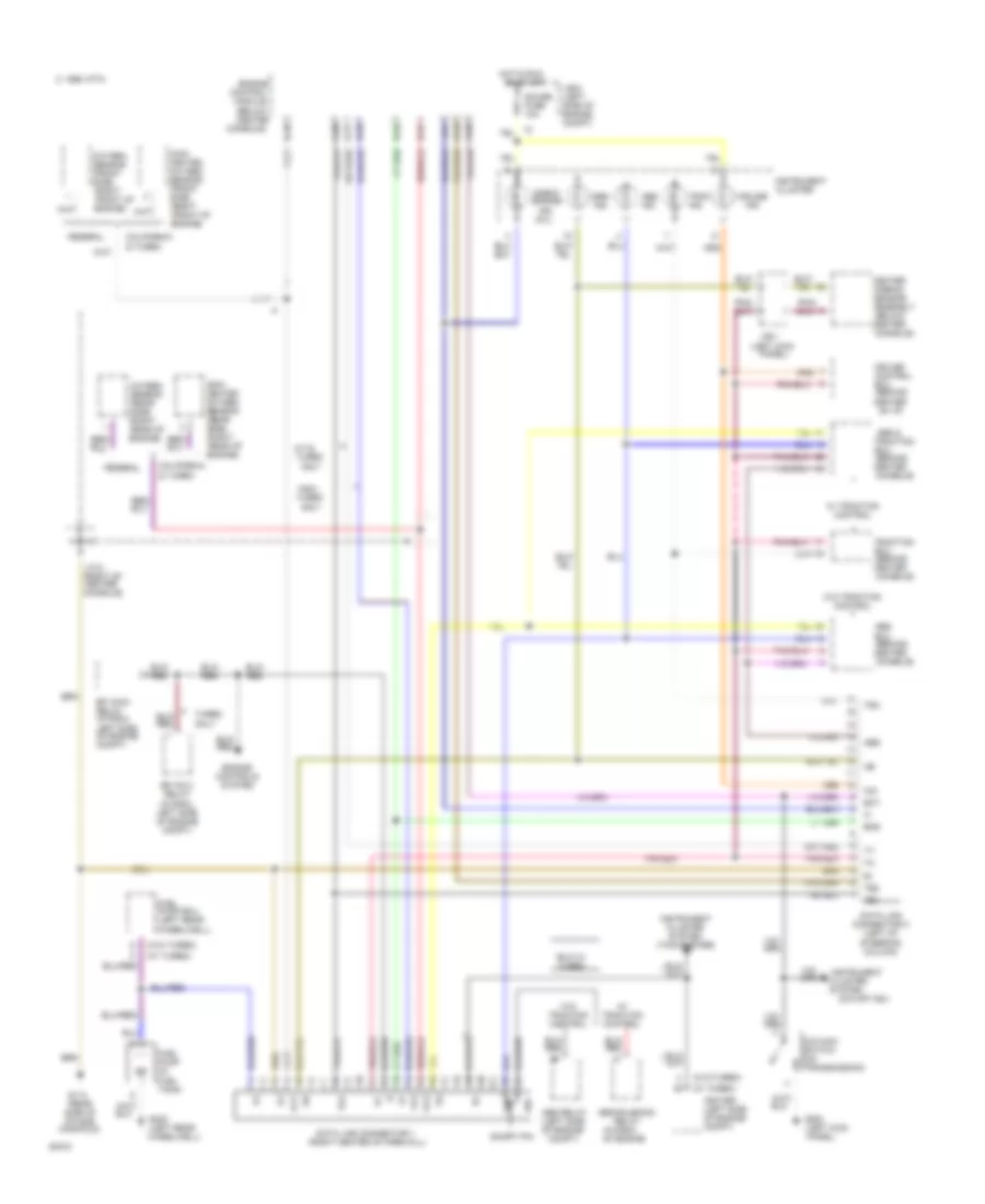
Data Link Connector Wiring Diagram for Toyota Supra 1994
List of elements for Data Link Connector Wiring Diagram for Toyota Supra 1994:
- (behind center
- (behind center of i/p)
- (below center
- (in r/b-5, of engine
- (left kick
- (left rear wheelwell)
- (mil)
- (o/d off ind.)
- (rear side of intake manifold)
- (right
- (right center of firewall)
- (w/ turbo)
- (w/o turbo)
- 1995 vftc c
- A-17
- A-19
- A-20
- A-28
- A-6
- A/d
- A/t & turbo
- Abs
- Abs &
- Abs ecu
- Abs ind.
- Abs relay (left side of engine
- Abs solenoid
- Assembly
- B-28
- B-29
- B-47
- B-48
- California & turbo
- Center airbag sensor
- Check engine
- Cluster system
- Compt)
- Console)
- Control
- Cruise
- Data link connector 1
- Data link connector 2 (left of steering column)
- Ect
- Ecu
- Efi main relay (in r/b-2, left side of engine compt)
- Efi no.2 relay (in r/b-2, left side of engine compt)
- Eng
- Engine
- Engine controls system
- Engine)
- Federal
- Front of
- Fuel pump (in fuel tank)
- Fuel pump ecu (left rear wheelwell)
- G112
- G200
- G402
- Gauge fuse 10a
- Hot in run
- Ig-
- Igniter (left side of engine compt)
- Ind.
- Instrument
- Instrument cluster
- Instrument cluster system (tachometer)
- J/b-1
- J/b-2 (left side of engine compt)
- J/c-2 (right of center console)
- Main heated oxygen sensor (front side)
- Main heated oxygen sensor (rear side)
- Module (below center
- Non- turbo
- O/d main switch (on transmission)
- Only
- Or start
- Ox1
- Ox2
- Oxygen sensor (front side)
- Oxygen sensor (rear side)
- Panel)
- Rear of engine)
- Relay
- Short pin
- Srs ind.
- Te1
- Te2
- Trac ind.
- Traction
- Trc
- Turbo only
- Vf2
- W/ traction control
- W/o traction control
 Русский