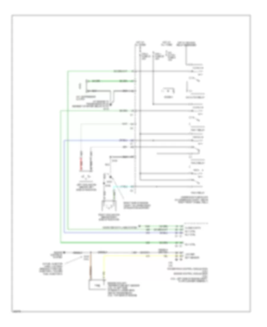
COOLING FAN
Cooling Fan Wiring Diagram for Chevrolet Uplander LT 2006
List of elements for Cooling Fan Wiring Diagram for Chevrolet Uplander LT 2006:
- (at engine to transmission stud nearest starter, below g113)
- (in fuel injector harn, 4 cm from breakout for fuel injector 2, toward fuel injector 3)
- (or 2761)
- (right side of engine compt, on upper front of radiator support)
- 3.5l
- 3.9l
- A/c compressor clutch
- A/c cltch fuse 6 10a
- A/c cltch relay
- Class 2 data
- Computer data lines system
- Diode 3
- Ect sensor
- Engine controls system
- Engine coolant temperature (ect) sensor (3.5l: in left side of rear cylinder head, above transmission) (3.9l: top rear of engine)
- Fan 1 fuse 29 30a
- Fan 1 relay
- Fan 2 fuse 33 40a
- Fan 2 relay
- Fan 3 relay
- G100
- G115
- Hot at all times
- Hot w/ ign main relay energized
- Left cooling fan (behind left side of radiator)
- Low ref
- Powertrain control module (pcm) (3.5l) engine control module (ecm) (3.9l) (3.5l: left side of engine compt, in air cleaner assembly)
- Red
- Right cooling fan (behind right side of radiator)
- Rly ctrl
- S102
- S106
- S140 (3.5l)
- Underhood fuse block (in underhood compt, above right front wheel well)
 English