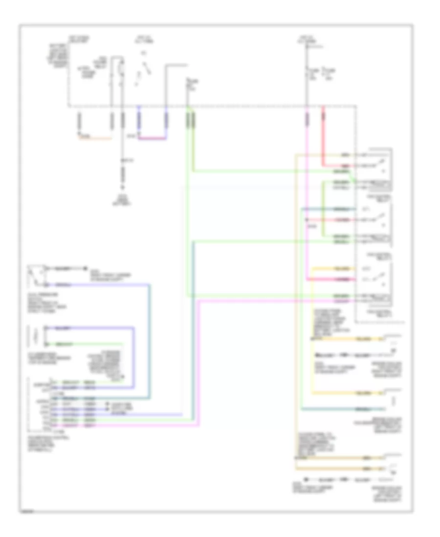
COOLING FAN
Cooling Fan Wiring Diagram, Except Hybrid for Ford Escape 2008

List of elements for Cooling Fan Wiring Diagram, Except Hybrid for Ford Escape 2008:
- (in engine control sensor & fuel charge wiring harness, before breakout to fuel injector 3)
- (in fuel shut off off solenoid wiring harness, near breakout to fuel injector 6)
- Acpsw
- Battery junction box (bjb) (left front of engine compt)
- C175b
- C175e
- Can+
- Can-
- Cec01
- Cec02
- Ch425
- Cht
- Computer data lines system
- Cooling fan relay
- Cooling fan resistor (2.3l) (left front of engine compt)
- Cylinder head temperature sensor (2.3l) (top of engine, on cylinder head)
- Dual pressure switch (right front of engine compt)
- Ect
- Engine control system
- Engine coolant temperature (ect) (3.0l) (rear of engine in water outlet)
- Engine cooling fan motor 1 (front of engine compt)
- Engine cooling fan motor 2 (front of engine compt)
- Fan ctrl
- Fuse 40a
- G102 (right front of engine compt)
- G103 (right front of engine compt)
- G104 (at left front corner of engine compt, near bjb)
- High speed fan control relay
- Hot at all times
- Hot in run or start
- Low speed fan control relay
- Pcm power diode
- Pcm power relay
- Power distribution system
- Powertrain control module (pcm) (3.0l: in recess on upper center of firewall) (2.3l: rear center of firewall)
- Re405
- Red
- S102
- S108 (in headlamp jumper wiring harness, near breakout to c139)
- S109
- S118
- S129
- Sigrtne
- Vdb04
- Vdb05
- Ve712
- Ve716
Cooling Fan Wiring Diagram, Hybrid for Ford Escape 2008
List of elements for Cooling Fan Wiring Diagram, Hybrid for Ford Escape 2008:
- (in dash panel to headlamp junction wiring harness, near breakout to battery junction box (bjb) s122
- (in dash panel to headlamp junction wiring harness, near breakout to battery junction box (bjb)) s120
- (in engine control sensor & fuel charge wiring harness, near breakout to coil on plug (cop) 4) s104
- Acpsw
- Battery junction box (bjb) (left rear of engine compt)
- C175b
- C175e
- Can+
- Can-
- Cec01
- Cec02
- Cec11
- Ch425
- Cht
- Computer data lines system
- Cylinder-head temperature sensor (top of engine)
- Dual pressure switch (right front of engine compt, near strut tower)
- Engine cooling fan dropping resistor 1 (left front of engine compt)
- Engine cooling fan motor 1 (left front of engine compt)
- Engine cooling fan motor 2 (right front of engine compt)
- Fan control relay 1
- Fan control relay 2
- Fan control relay 3
- Fc1
- Fc2
- Fc3
- Fuse 10a
- Fuse 40a
- G102 (right front corner of engine compt)
- G103 (right front corner of engine compt)
- G104 (near battery)
- Hot at all times
- Hot in run or start
- Pcm power diode
- Pcm power relay
- Powertrain control module (pcm) (rear center of firewall)
- Re405
- Red
- S115
- S125
- S126
- S134
- S140
- Sigrtne
- Vdb04
- Vdb05
- Ve712