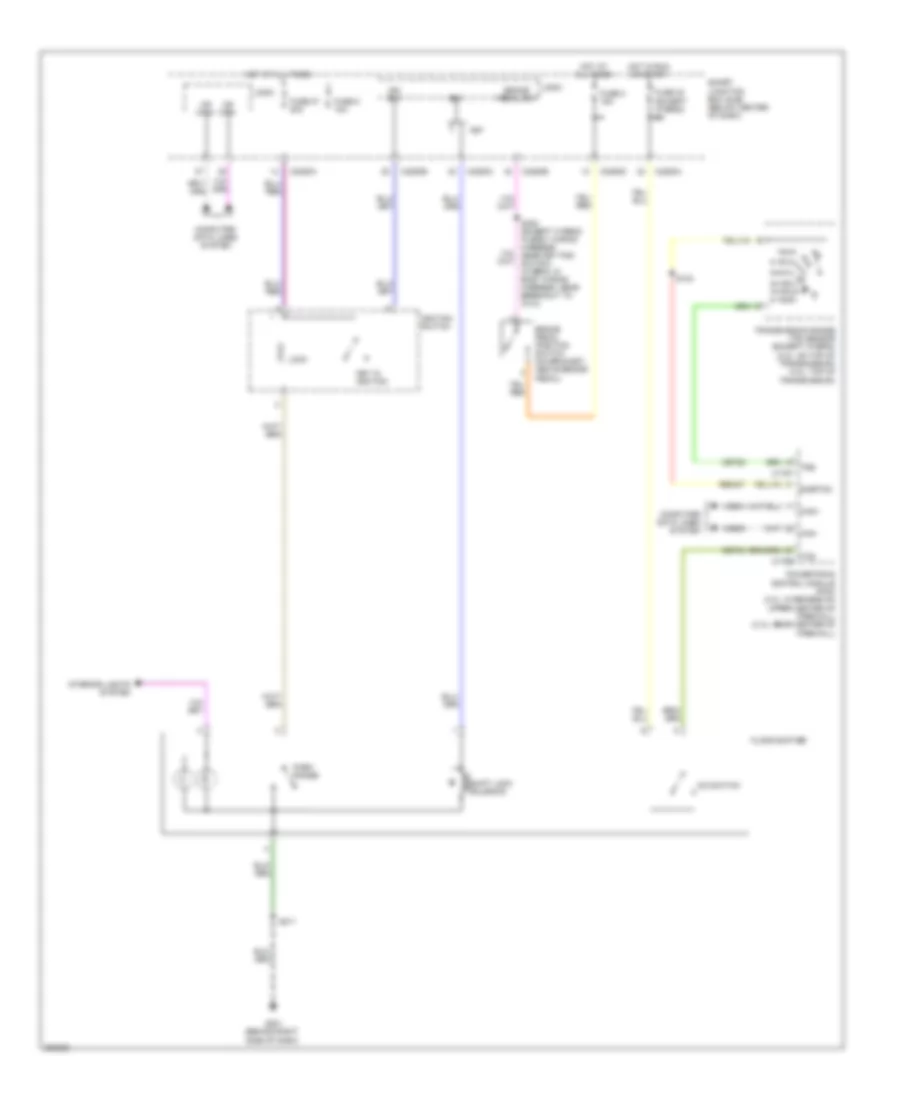
SHIFT INTERLOCK
Shift Interlock Wiring Diagram for Ford Escape 2008
List of elements for Shift Interlock Wiring Diagram for Ford Escape 2008:
- Brake pedal position switch (on bracket, above brake pedal)
- Brake pedal sw
- Bs1
- C2280a
- C2280b
- C2280c
- C2280d
- Can+
- Can-
- Cet34
- Cet52
- Computer data lines system
- Fet
- Floor shifter
- Fuse 2 15a
- Fuse 27 20a
- Fuse 30 (except hybrid) 5a
- Fuse 5 10a
- G201 (behind right side of dash)
- Hot at all times
- Hot in run or start
- Ign sw
- Ignition switch
- Interior lights system
- Key in ignition
- Lock
- Logic
- Ms can+
- Ms can-
- N d
- O/d switch
- Park range
- Powertrain control module (pcm) (3.0l: in recess on upper center of firewall) (2.3l: rear center of firewall)
- Re5407
- S123
- S211
- S308 (except hybrid: in body wiring harness, near key pad switch) (hybrid: in body wiring harness, near breakout to c314)
- Shift lock solenoid
- Sigrtnc
- Smart junction box (sjb) (below center of dash)
- Tcs c175b
- Transmission range (tr) sensor (except hybrid) (2.3l: on top of transmission) (3.0l: top of transmission)
- Trs c175t
- Vdb04
- Vdb05
 English