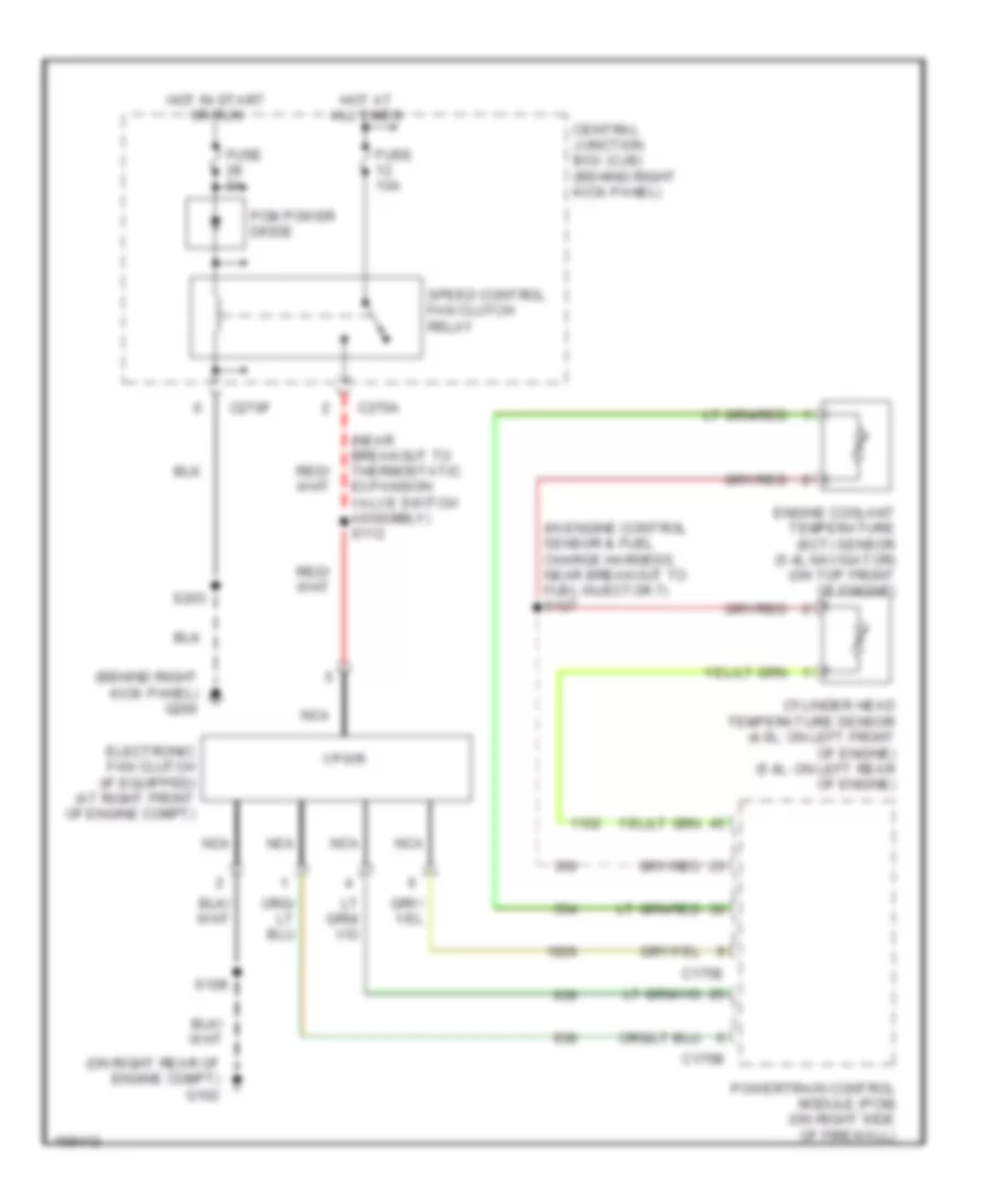
COOLING FAN
Cooling Fan Wiring Diagram for Lincoln Navigator 2003
List of elements for Cooling Fan Wiring Diagram for Lincoln Navigator 2003:
- (behind right kick panel) g200
- (in engine control sensor & fuel charge harness, near breakout to fuel injector 7) s127
- (near breakout to thermostatic expansion valve switch assembly) s112
- (on right rear of engine compt) g102
- C175b
- C175e
- C270a
- C270f
- Central junction box (cjb) (behind right kick panel)
- Cylinder head temperature sensor (4.6l: on left front of engine) (5.4l: on left rear of engine)
- Electronic fan clutch (if equipped) (at right front of engine compt)
- Engine coolant temperature (ect) sensor (5.4l navigator) (on top front of engine)
- Fuse 10a
- Fuse 5a
- Hot at all times
- Hot in start or run
- Nca
- Pcm power diode
- Powertrain control module (pcm) (on right side of firewall)
- S108
- S203
- Speed control fan clutch relay
- Vpwr
 English