POWER DISTRIBUTION
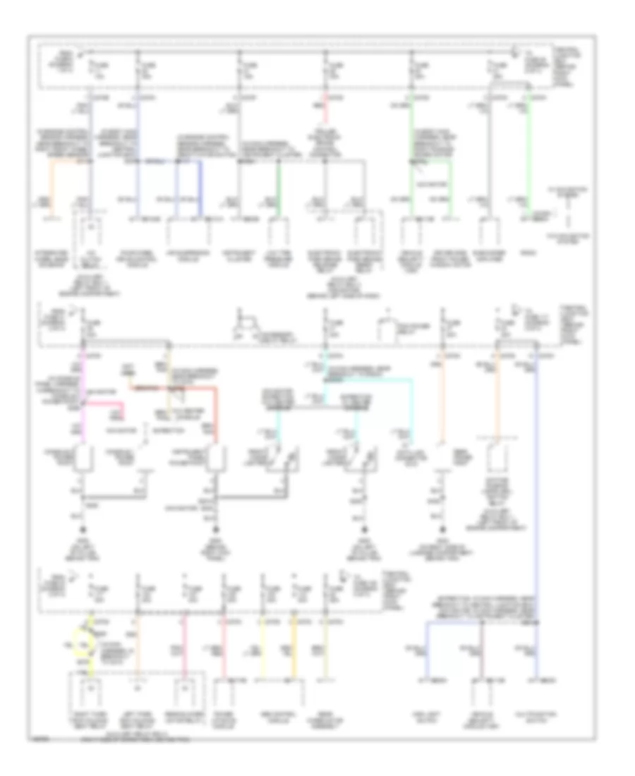
Power Distribution Wiring Diagram (1 of 4) for Lincoln Navigator 2003

List of elements for Power Distribution Wiring Diagram (1 of 4) for Lincoln Navigator 2003:
- (behind right kick panel) central junction box
- (in body main harness, near breakout to c316) s377
- (in body main harness, near breakout to c800) s379
- (in body main harness, near breakout to central junction box) s392
- (in body main harness, near breakout to restraints control module) s372
- (in console panel harness, in breakout to c314)
- (in engine control sensor harness, near breakout to thermostatic expansion valve switch assembly) s133
- (in main harness, near breakout to glove box lamp) s203
- (in main harness, near breakout to instrument cluster) s277
- (in power seats harness, near breakout to driver's side climate controlled seat fan) s384
- (in rear lamp connector harness, near breakout to c410) s448
- (navigator: in main harness, near breakout to glove box lamp) (expedition: in main harness, near breakout to brake pedal position switch) s2001
- (not used)
- Auxiliary relay box 1 (left front of engine compt)
- Auxiliary relay box 2 (right side of cargo area, behind trim)
- Auxiliary relay box 3 (behind left side of dash)
- Battery
- Battery charge trailer tow relay
- Battery saver relay
- Brake pedal position switch
- Breakout to auxiliary relay box 1) s123
- C102b
- C175b
- C205a
- C2113b
- C228b
- C270a
- C270b
- C270e
- C270f
- C270j
- C294c
- C341c
- C349a
- C4174d
- C577 c527
- Cd changer
- Clock
- Deactivator switch
- Driver seat module
- Dvd player
- Electronic automatic temperature control (eatc) module
- Except manual a/c
- Expedition
- Exterior rear view mirror switch
- Floor shifter
- Fog lamp relay
- From a fuse 26 (diagram 1 of 4)
- Front blower motor relay
- Front function selector switch assembly
- Fuse 10a
- Fuse 15a
- Fuse 20a
- Fuse 30a
- Fuse 40a
- Fuse 7.5a
- Generator
- Horn relay
- Indicator flasher relay
- Ivd stop lamp relay
- Left power seat switch
- Left third row folding seat relay
- Main light switch
- Manual a/c
- Navigator
- Nca
- Parking lamp trailer tow relay
- Power liftgate module
- Powertrain control module (pcm)
- Rear integrated control panel (ricp)
- Red
- Reversing lamp trailer tow relay
- Right third row folding seat relay
- S1001 (in alternator rectifier system harness, in breakout to battery)
- S1002 (in alternator rectifier system harness, in breakout to battery)
- S388
- Speed control fan clutch relay
- Starter motor
- Starter relay
- Sunload sensor
- To fuse 11 (diagram 2 of 4)
- To fuse 2 (diagram 1 of 4)
- Vehicle security module (vsm)
- W/ power folding mirror
- W/ power folding seats
- W/o power folding mirror
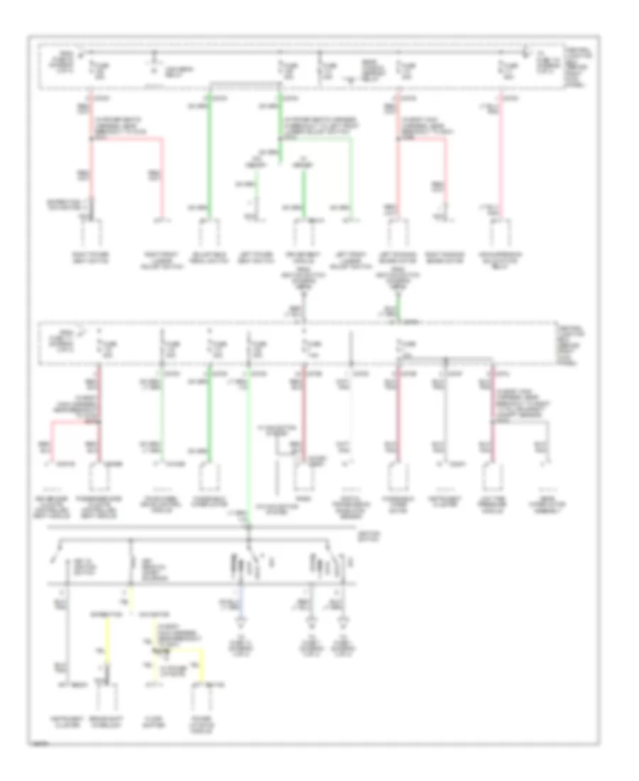
Power Distribution Wiring Diagram (2 of 4) for Lincoln Navigator 2003
List of elements for Power Distribution Wiring Diagram (2 of 4) for Lincoln Navigator 2003:
- (expedition: in main harness, near breakout to central junction box) (navigator: in main harness, near breakout to instrument cluster) s212
- (in body main harness, near breakout to central junction box) s357
- (in body main harness, near breakout to right running board motor) s391
- (in console panel harness, in breakout to console 2 power point) s396
- (in engine control sensor harness, near breakout to deactivator switch) s117
- (in engine control sensor harness, near breakout to right front wheel speed sensor) s113
- (in main harness, in breakout to c214)
- (in main harness, near breakout to instrument cluster) s238
- (navigator)
- (not used)
- A/c clutch relay
- Abs control module
- Accessory delay relay
- Air suspension module
- Auxiliary relay box 1 (left front of engine compartment)
- Auxiliary relay box 2 (right side of cargo area, behind trim)
- Auxiliary relay box 3 (navigator) (behind left side of dash)
- C202c
- C205a
- C2113b
- C2131a
- C2188a c290a
- C220b
- C270b
- C270c
- C270d
- C270f
- C270g
- C270h
- C270k
- C270m
- C270n
- C3184b
- C4174b
- Central junction box (behind right kick panel)
- Console 1 power point
- Console 2 power point
- Data link connector (dlc)
- Daytime running lamps (drl) ignition relay
- Driver side front power window motor
- Electronic park brake release relay
- Electronic park brake reset relay
- Expedition
- Expedition w/ center console
- Four-wheel drive control module
- From b fuse 6 (diagram 1 of 4)
- From c fuse 31 (diagram 2 of 4)
- From d fuse 40 (diagram 2 of 4)
- Front cigar lighter
- Fuse 10a
- Fuse 15a
- Fuse 20a
- Fuse 25a
- Fuse 30a
- G200 (behind right kick panel)
- G300 (on left ``b" pillar, behind trim)
- G404 (on right side of luggage compartment, behind trim)
- Instrument cluster
- Instrument panel power point
- Integrated wheel ends solenoid
- Left third row folding seat relay
- Low tire pressure module
- Main light switch
- Multifunction switch
- Navigator
- Navigator, expedition w/o center console
- Pcm power relay
- Power liftgate module
- Radio
- Rear blower motor relay
- Rear power point
- Rear wiper motor assembly
- Red
- Right third row folding seat relay
- S2018
- S202
- S205
- S279
- S280
- S436
- Subwoofer amplifier
- To fuse 108 (diagram 3 of 4)
- To fuse 117 (diagram 2 of 4)
- To fuse 39 (diagram 2 of 4)
- Trailer electronic brake control connector
- Vehicle security module (vsm)
- W/ navigation system
- W/o center console
- W/o navigation system
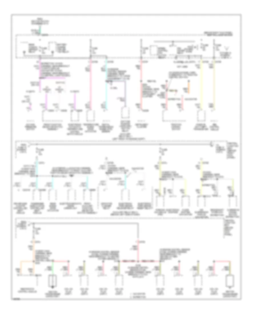
Power Distribution Wiring Diagram (3 of 4) for Lincoln Navigator 2003
List of elements for Power Distribution Wiring Diagram (3 of 4) for Lincoln Navigator 2003:
- (expedition) a
- (in body main harness, near breakout to c316) s375
- (in body main harness, near breakout to g301) s395
- (in body main harness, near breakout to right ``c" pillar safety canopy sensor) s315
- (in power seats harness, in breakout to left front lumbar adjust switch) s310
- (in power seats harness, near breakout to c316) s311
- (navigator)
- Acc
- Adjustable pedal switch
- Air suspension solid state relay
- Brake shift interlock
- C2188c c290a
- C220a
- C270b
- C270c
- C270d
- C270e
- C270f
- C270g
- C270h
- C270j
- C270m
- C3031b
- C3036b
- C3184b
- C341a
- C4174d
- Central junction box (behind right kick panel)
- Digital transmission rane (dtr) sensor
- Driver seat module
- Driver side climate controlled seat module
- Expedition
- Floor shifter
- Four-wheel drive control module
- From e fuse 38 (diagram 2 of 4)
- From f fuse 111 (diagram 3 of 4)
- From ignition switch (diagram 3 of 4)
- Fuse 10a
- Fuse 30a
- Fuse 40a
- Fuse 50a
- Fuse 7.5a
- High beam relay
- Ignition switch
- Instrument cluster
- Key in ignition switch
- Key removal inhibit solenoid
- Left front lumbar adjust switch
- Left power seat switch
- Left running board motor
- Lock
- Low tire pressure module
- Navigator
- Nca
- Off
- Passenger side climate controlled seat module
- Power liftgate module
- Radio
- Rear window defrost relay
- Rear wiper motor assembly
- Right front lumbar adjust switch
- Right power seat switch
- Right running board motor
- Run
- Start
- To fuse 1 (diagram 3 of 4)
- To fuse 118 (diagram 3 of 4)
- To fuse 13 (diagram 4 of 4)
- To fuse 7 (diagram 3 of 4)
- W/ memory
- W/ navigation system
- W/ power liftgate
- W/o memory
- W/o navigation system
- Windshield wiper motor
Power Distribution Wiring Diagram (4 of 4) for Lincoln Navigator 2003
List of elements for Power Distribution Wiring Diagram (4 of 4) for Lincoln Navigator 2003:
- (behind right kick panel) central junction box
- (expedition)
- (in body main harness, near breakout to c316) s318
- (in body main harness, near breakout to c800) s319
- (in body main harness, near breakout to restraints control module) s320
- (in console panel harn, in breakout to traction control switch)
- (in engine control sensor & fuel charge harness, near breakout to heated oxygen sensor 11) s132
- (in engine control sensor & fuel charge harness, near breakout to heated oxygen sensor 21) s124
- (in interior illumination harness, near breakout to front auxiliary function selector switch assembly) s903
- (in main harness, near breakout to c210) s221
- (left front of engine compt)
- (navigator)
- A/c high pressure switch
- Abs control module
- Air suspension module
- Auxiliary relay box 1
- Auxiliary relay box 3 (behind left side of dash)
- Battery charge trailer tow relay
- Brake shift interlock
- C2131a
- C220b
- C228b
- C270b
- C270d
- C270e
- C270f
- C270g
- C270j
- C294b
- C294c
- C3031b
- C3036b
- C310a
- C4014b
- C989b
- Central junction box (behind right kick panel)
- Coil on plug (cop) 1
- Coil on plug (cop) 2
- Coil on plug (cop) 3
- Coil on plug (cop) 4
- Coil on plug (cop) 5
- Coil on plug (cop) 6
- Coil on plug (cop) 7
- Coil on plug (cop) 8
- Daytime running lamps (drl) ignition relay
- Digital transmission range (dtr) sensor
- Driver side climate controlled seat module
- Electrochromatic inside mirror unit
- Electronic automatic temperature control (eatc) module
- Electronic compass
- Electronic park brake release relay
- Electronic park brake reset relay
- Expedition
- Floor shifter (navigator)
- From fuse 27 k (diagram 4 of 4)
- From ignition switch (diagram 3 of 4)
- From j fuse 16 (diagram 4 of 4)
- Front auxiliary function selector switch assembly
- Front function selector switch assembly
- Fuse 10a
- Fuse 5a
- Harness, near breakout to c219) s228
- Ignition transformer capacitor 1
- Ignition transformer capacitor 2
- Indicator flasher relay
- Instrument cluster
- Navigator
- Nca
- Not used
- Overdrive cancel switch (expedition)
- Parking aid module (pam)
- Passenger side climate controlled seat module
- Passive anti-theft transceiver
- Pcm power diode
- Pcm power relay
- Rear blend door actuator
- Rear window defrost relay
- Restraints control module
- S129 (in engine control sensor & fuel charge harness, near breakout to coil on plug 4)
- S282 (in main harness, near breakout to instrument cluster)
- S387 (exped- ition)
- Speed control fan clutch relay
- Tan/ red
- Temperature blend door actuator
- To eatc module) (navigator: in main harness, near breakout to central junction box) s241
- To fuse 18 (diagram 4 of 4)
- To fuse 19 (diagram 4 of 4)
- Traction control switch
- W/ drl
- W/ eatc
- W/ manual a/c