CRUISE CONTROL
2.4L
2.4L, Cruise Control Wiring Diagram (1 of 2) for Honda Accord DX 2004

List of elements for 2.4L, Cruise Control Wiring Diagram (1 of 2) for Honda Accord DX 2004:
- (or pnk)
- A/t
- A/t comm
- Act clutch
- At/mt sw
- Brake pedal position switch (on brake pedal support)
- Brake switch
- Clutch pedal position switch (except usa dx: under left side of dash)
- Control block
- Cruise control actuator (except usa dx: at right side of firewall)
- Cruise control unit (2.4l & except usa dx: behind left side of dash)
- Cruise lamp
- D11
- D12
- E26
- Ecm/pcm (under middle of dash)
- Fuse 13 20a
- Fuse 18 15a
- Fuse 7 7.5a
- G202
- G501 (behind left side of dash)
- Ground
- Horn relay
- Hot at all times
- Hot in on or start
- Ignition input
- Junction connector c406 (below left side of dash)
- Junction connector c556 (behind glove box)
- M/t
- Main sw
- Main sw pwr
- Motor close
- Motor open
- N21
- N29
- Navigation unit (ex-l: in trunk, under middle of rear shelf)
- Pnk
- Red
- Relay control module
- Resume sw
- Set sw input
- Signal input
- Under-dash fuse/relay box (behind left kick panel)
- Under-hood fuse/relay box (on left rear corner of engine compt, forward of strut tower)
- Vss
- Vss input
- Vss output
- X28
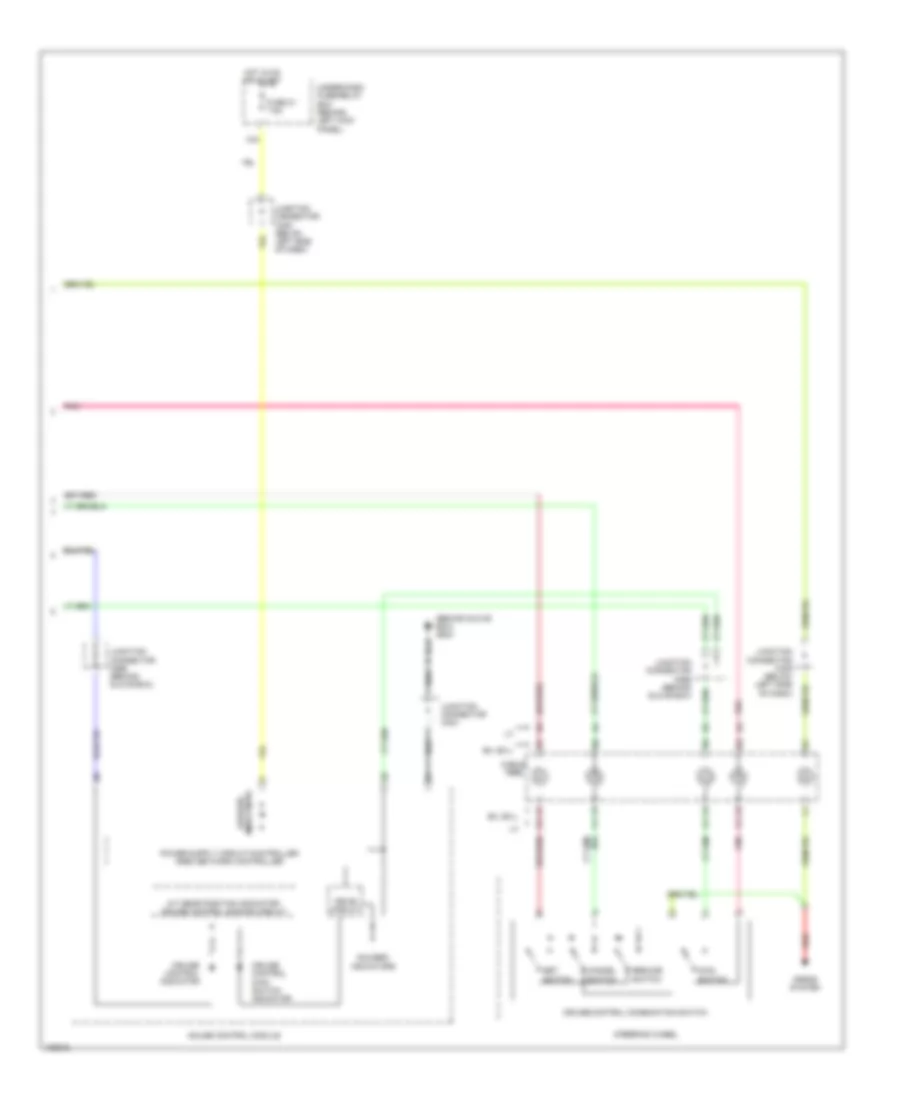
2.4L, Cruise Control Wiring Diagram (2 of 2) for Honda Accord DX 2004
List of elements for 2.4L, Cruise Control Wiring Diagram (2 of 2) for Honda Accord DX 2004:
- (behind glove box) g503
- A/t gear position indicator/ cruise control dimming circuit
- Cable reel
- Cancel switch
- Cruise control combination switch
- Cruise control indicator
- Cruise control main switch indicator
- Drive circuit
- Ex, ex-l
- Fuse 21 7.5a
- Gauge control module
- Gauges/ indicators
- Horns system
- Hot in on or start
- Indicators gauges/
- Junction connector c404
- Junction connector c405 (below left side of dash)
- Junction connector c556 (behind glove box)
- Main switch
- Pnk
- Red
- Resume switch
- Set switch
- Steering wheel
- Under-dash fuse/relay box (behind left kick panel)
- X34
3.0L
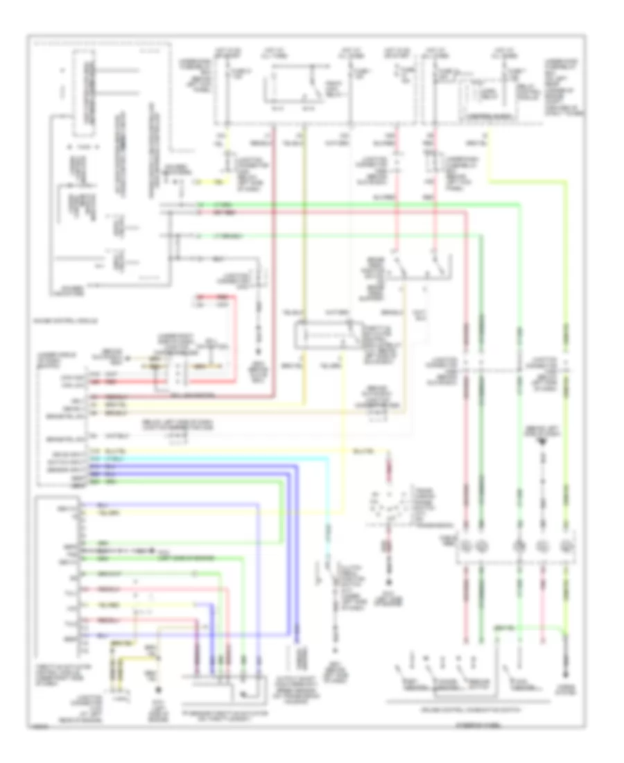
3.0L, Cruise Control Wiring Diagram for Honda Accord DX 2004
List of elements for 3.0L, Cruise Control Wiring Diagram for Honda Accord DX 2004:
- (behind glove box)
- (behind glove box) g503
- (behind left side of dash) g501
- (below left side of dash) junction connector c406
- (under middle of dash) ecm/pcm
- (under right side of dash) junction connector c555
- A13
- A15
- A26
- Brake pdl sw
- Brake pedal position switch (on brake pedal support)
- C19
- Cable reel
- Can high
- Can low
- Cancel switch
- Clutch pedal position switch (m/t) (under left side of dash)
- Control block
- Cruise control combination switch
- Cruise control dimming circuit a/t gear position indicator/
- Cruise control indicator
- Cruise control main switch indicator
- D14
- Dbw m+
- Dbw m-
- Dbwrly
- Drive circuit
- Drive input
- E25
- E26
- Ex-l navigation
- Fuse 1 15a
- Fuse 13 20a
- Fuse 15a
- Fuse 21 7.5a
- Fuse 7 7.5a
- G101 (left side of engine)
- G501 (behind left side of dash)
- G503 (behind glove box)
- Gauge control module
- Gauges/ indicators
- Horn relay
- Horns system
- Hot at all times
- Hot in on or start
- Junction connector c103 (at left rear of engine)
- Junction connector c404
- Junction connector c405 (below left side of dash)
- Junction connector c556
- Junction connector c556 (behind glove box)
- Main switch
- Mrly
- N21
- N29
- Network transceiver fast controller area
- Output shaft (countershaft) speed sensor (on transmission housing)
- Pg2
- Pgm-fi main relay 1
- Pnk
- Red
- Relay control module
- Resume switch
- Sedf
- Sefd
- Sensor input
- Sensor output
- Set switch
- Steering wheel
- Switch input
- Thl1
- Thl2
- Throttle actuator control module (under right side of dash)
- Throttle actuator control module relay (3.0l: behind left side of glove box)
- Tp sensor/throttle actuator (on throttle body)
- Trans- mission range switch (a/t) (on transmission)
- Under-dash fuse/relay box (behind left kick panel)
- Under-hood fuse/relay box (on left rear corner of engine compt, forward of strut tower)
- Vcc
- X23
- X28
- X34