CRUISE CONTROL
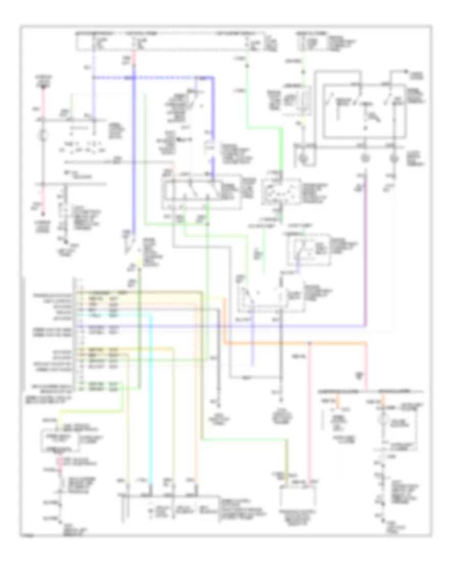
Cruise Control Wiring Diagram for Mercury Villager GS 1996
List of elements for Cruise Control Wiring Diagram for Mercury Villager GS 1996:
- "cruise" indicator
- "on"
- "on" input
- (analog) (electronic)
- (behind left side of i/p, taped to main harness)
- (left kick panel)
- (right side of engine, compartment on front of strut tower)
- Actuator
- Analog cluster
- Anti- theft relay
- Brake on/off (boo) switch (on brake pedal suport)
- Brake on/off sw
- C266
- C268
- C268 c272
- C272
- C274
- Cancel
- Clock- spring ring assembly
- Cluster
- Ej04
- Ej06
- Ej07
- Ej08
- Ej09
- Ej10
- Ej14
- Ej15
- Ej16
- Ej40
- Eje1
- Ejo1
- Ejo2
- Electronic cluster
- Engine compartment fuse/relay panel
- Engine compartment fuse/relay panel junction connector #1
- Engine compt fuse/ relay panel
- Fuse 10a
- Fuse 15a
- G100 (front of left front fender)
- G200
- G200 (left kick panel)
- G202 (behind left side of i/p)
- G203 (right kick panel)
- Ground
- Horn fuse 15a
- Horn relay (coil)
- Horns system
- Hot at all times
- Hot in start or run
- I/p fuse/ relay panel
- Indicator
- Inhibit relay
- Input
- Inst clstr/tcm
- Instrument
- Instrument cluster
- Interior lights system
- Joint connector #1
- Joint connector #1 (behind left side of i/p, taped to main harness)
- Nca
- Off
- Ohms
- Output
- Pnk
- Pnk/
- Red
- Red/
- Resume/ accel
- Set/ coast
- Shift lock solenoid/ park position switch
- Spd cont on/off sw
- Speed control
- Speed cont dis sw
- Speed cont sw assm
- Speed control actuator
- Speed control disengage switch (on brake pedal support)
- Speed control hold relay
- Speed control module (below center of i/p)
- Speed control on/off switch
- Speed control switch assembly
- Speed signal
- Transaxle cont mod
- Transaxle control module (tcm) (behind right side of i/p)
- Transaxle)
- Transmission range (tr) sensor (on front of transaxle)
- Vacuum pump motor
- Vacuum solenoid
- Vehicle speed sensor (vss) (on rear of
- Vehicle speed signal
- Vent solenoid
- W/ anti-theft
- W/o anti-theft
 English