INSTRUMENT CLUSTER
Instrument Cluster Wiring Diagram, Analog Cluster (1 of 2) for Mercury Villager GS 1996

List of elements for Instrument Cluster Wiring Diagram, Analog Cluster (1 of 2) for Mercury Villager GS 1996:
- (above rear axle)
- (behind left side of i/p)
- (behind top left side of i/p, taped to main harness)
- (left kick panel)
- 10a
- 10b
- 10c
- 11b
- 11c
- 12b
- 12c
- 2 pole speed sensor
- 56 ohms
- Air bag diagnostic monitor (behind left side of i/p)
- Air bag ind.
- Anti- slosh module
- Anti-lock warning ind.
- Av02
- Av32
- Brake warning ind.
- C266
- C268
- C270
- Charge warning ind.
- Coolant temp.
- Coolant temperature sender (top right rear of engine)
- Cruise ind.
- Door ajar ind.
- Ej07
- Ej10
- Ej17
- Engine coolant temp. gauge
- Engine oil pressure switch (lower right front of engine, near oil filter)
- Engine speed
- Exterior lights system (hazard switch & combination switch)
- Fuel gauge
- Fuel gauge sender
- Fuel level
- Fuel pump module (below rear of vehicle, inside fuel tank)
- Fuse 10a
- G200
- G202
- G415
- Gnd
- Headlights system (combination switch)
- Hi beam ind.
- Hot in start or run
- I/p fuse/ relay panel
- Ign
- Illum. dim
- Illum. lamps
- Illum. power
- Instrument cluster
- J/c 1
- Left turn ind.
- Low fuel warning ind.
- Low oil press. ind.
- Low washer fluid ind.
- Malfunction ind.
- Nca
- Nr01
- O/d off ind.
- Pnk
- Powertrain control module (pcm) (behind top right side of i/p, behind glove box)
- Prndl illum. dim
- Prndl illum. lamp
- Prndl illum. pwr
- Ps15
- Red
- Right turn ind.
- Seat belt warning ind.
- Smart entry control (sec)/timer module (behind center of i/p)
- Speed control module (below center of i/p, mounted on center i/p brace support)
- Speedometer
- Tachometer
- Transaxle control module (tcm) (behind top right side of i/p, behind glove box)
- V ref
- Vehicle speed in
- Vehicle speed out
- Vehicle speed sensor (left side of engine, on rear of transaxle)
- Zy03
- Zy24
- Zy27
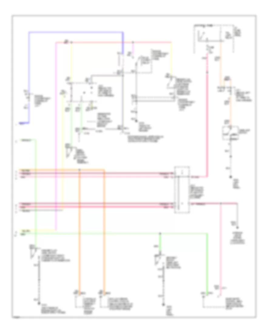
Instrument Cluster Wiring Diagram, Analog Cluster (2 of 2) for Mercury Villager GS 1996
List of elements for Instrument Cluster Wiring Diagram, Analog Cluster (2 of 2) for Mercury Villager GS 1996:
- (below center of i/p, mounted on center i/p support brace)
- (front of left front fender)
- (left kick panel)
- (left rear of engine compt, on brake fluid reservoir)
- (lower right front of engine compt, on washer fluid reservoir)
- (on park brake assembly)
- (right rear of engine compt, on side of strut tower)
- Anti-lock brake control module
- Brake fluid level switch
- Bulb check relay
- C133
- C135
- Daytime running lamps module (right side of engine compt, on front of strut tower)
- Engine compartment fuse/relay panel
- Engine compartment fuse/relay panel j/c 1
- Engine compartment fuse/relay panel j/c 2
- Fuse 7.5a
- G100
- G103
- G200
- Generator/ voltage regulator (lower right front of engine)
- Head
- Headlamp switch
- Hot at all times
- Hydraulic actuator assembly (right front of engine compt)
- I/p fuse/ relay panel
- Interior lights system (instrument illumination)
- J/c 1 (behind left side of i/p, taped to main harness)
- J/c 2 (behind top left side of i/p, right of instrument cluster)
- J/c 2 (behind top left side of i/p, taped to main harness)
- Jc11
- Nca
- Off
- Park
- Park brake switch
- Pnk
- Seat belt switch (near left front seat belt buckle)
- Smart entry control (sec)/ timer module (behind center of i/p)
- Tail lamp relay
- W/ drl
- Washer fluid level switch
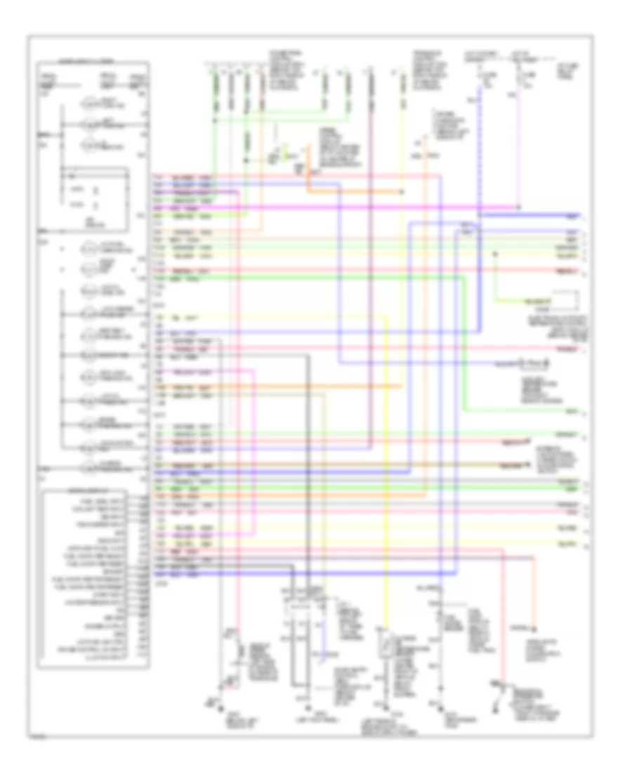
Instrument Cluster Wiring Diagram, Electronic Cluster (1 of 2) for Mercury Villager GS 1996
List of elements for Instrument Cluster Wiring Diagram, Electronic Cluster (1 of 2) for Mercury Villager GS 1996:
- (behind left side of i/p)
- (below rear of vehicle, inside fuel tank)
- (left kick panel)
- (left rear of engine compt, on side of strut tower)
- 10a
- 10b
- 10c
- 11a
- 11b
- 11c
- 12a
- 12b
- 12c
- 13a
- 13c
- 14a
- 14c
- 15a
- 15c
- 16c
- 17c
- 18c
- 19c
- 20c
- Air bag diagnostic monitor (behind left side of i/p)
- Air bag ind.
- Anti-lock warning ind.
- Av02
- Av05
- Av32
- Bat
- Brake warning ind.
- Bs29
- C20
- C2029
- C272
- C274
- C276
- Charge warning ind.
- Coolant temp input
- Coolant temperature sender (top right rear of engine)
- Cruise control on input
- Data input-fuel flow
- Digital display
- Dimmer output
- Door ajar ind.
- Ej07
- Ej10
- Ej17
- Electronic automatic temperature control (eatc) module (behind center of i/p)
- Eng/met
- Engine oil pressure switch (lower right front of engine, near oil filter)
- Exterior lights system (hazard switch & combination switch)
- Fuel computer reset
- Fuel computer select
- Fuel computer trip/reset
- Fuel computer trip/select
- Fuel gauge sender
- Fuel level input
- Fuel pump module
- Fuse 10a
- G102
- G200
- G202
- G415 (above rear axle)
- Gnd
- Grd
- Headlights system (combination switch)
- Hi beam ind.
- Hot at all times
- Hot in start or run
- I/p fuse/ relay panel
- Ig01
- Ig91
- Ig92
- Ign
- Illum dim input
- Instrument cluster
- J/c 1 (behind top left side of i/p, taped to main harness)
- La03
- Lb15
- Lb16
- Left turn ind.
- Low fuel ind ctrl
- Low fuel warning ind.
- Low oil level ind.
- Low oil press. ind.
- Low washer fluid ind.
- Ma01
- Ma02
- Ma03
- Ma04
- Ma06
- Ma07
- Ma11
- Ma12
- Ma14
- Ma15
- Ma16
- Ma17
- Ma41
- Mae1
- Mae2
- Malfunction ind.
- Md01
- Mj01
- Mje2
- Nb01
- Nca
- Nf01
- Ni03
- Nm01
- Nn01
- Nr01
- O/d off ind.
- O/s temp sensor input
- Outside air temperature sensor (lower center front of vehicle, below front bumper)
- Pnk
- Powertrain control module (pcm) (behind top right side of i/p, behind glove box)
- Prndl illum. dim
- Prndl illum. lamp
- Prndl illum. pwr
- Ps15
- Red
- Right turn ind.
- Seat belt warning ind.
- Smart entry control (sec)/ timer module (behind center of i/p)
- Speed control module (below center of i/p, mounted on center i/p brace support)
- Start input
- Tachometer input
- Transaxle control module (tcm) (behind top right side of i/p, behind glove box)
- Vehicle speed sensor (left side of engine, on rear of transaxle)
- Vss grd
- Vss input
- Vss ouput
- Zy03
- Zy24
- Zy27
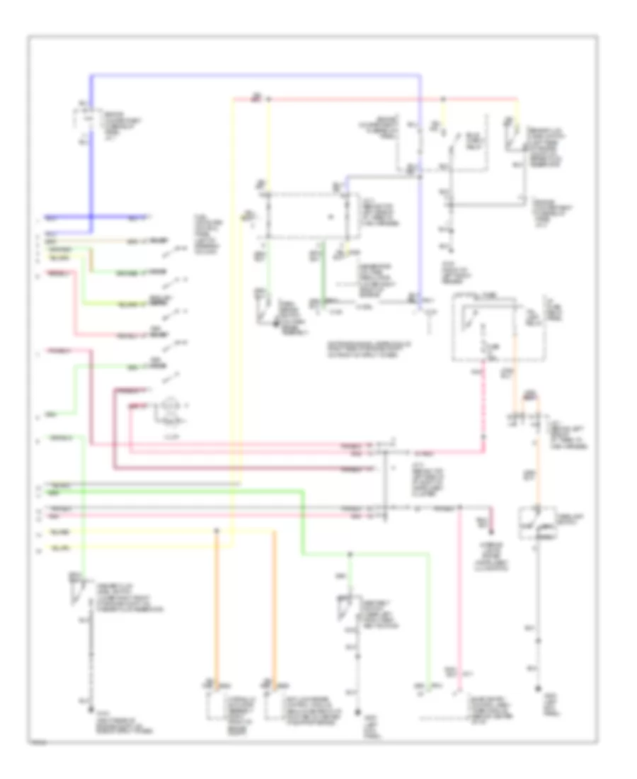
Instrument Cluster Wiring Diagram, Electronic Cluster (2 of 2) for Mercury Villager GS 1996
List of elements for Instrument Cluster Wiring Diagram, Electronic Cluster (2 of 2) for Mercury Villager GS 1996:
- (below center of i/p, mounted on center i/p support brace)
- (front of left front fender)
- (left kick panel)
- (left rear of engine compt, on brake fluid reservoir)
- (lower right front of engine compt, on washer fluid reservoir)
- (on park brake assembly)
- (right rear of engine compt, on side of strut tower)
- Anti-lock brake control module
- Brake fluid level switch
- Bulb check relay
- C133
- C135
- Daytime running lamps module (right side of engine compt, on front of strut tower)
- Engine compartment fuse/relay panel
- Engine compartment fuse/relay panel j/c 1
- Engine compartment fuse/relay panel j/c 2
- English/ metric
- Fuel computer control panel (left of steering column)
- Fuse 7.5a
- G100
- G103
- G200
- Generator/ voltage regulator (lower right front of engine)
- Head
- Headlamp switch
- Hot at all times
- Hydraulic actuator assembly (right front of engine compt)
- I/p fuse/ relay panel
- Illum.
- Interior lights system (instrument illumination)
- J/c 1 (behind left side of i/p, taped to main harness)
- J/c 2 (behind top left side of i/p, right of instrument cluster)
- J/c 2 (behind top left side of i/p, taped to main harness)
- Jc11
- Nca
- Off
- Park
- Park brake switch
- Pnk
- Reset
- Seat belt switch (near left front seat belt buckle)
- Select
- Smart entry control (sec)/ timer module (behind center of i/p)
- Tail lamp relay
- Trip reset
- Trip select
- W/ drl
- Washer fluid level switch