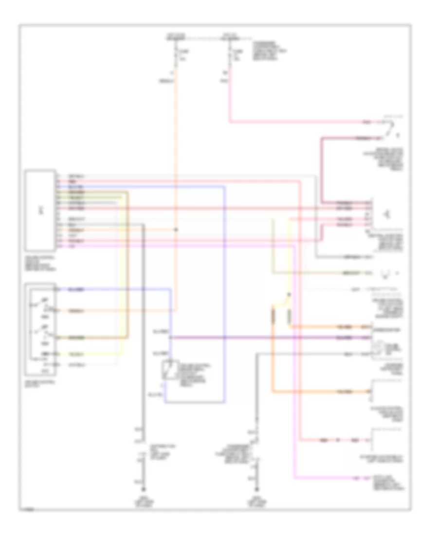
CRUISE CONTROL
Cruise Control Wiring Diagram for Volvo V40 2001
List of elements for Cruise Control Wiring Diagram for Volvo V40 2001:
- A13
- A18
- Acc
- B15
- Brake lights/ unlocking selector lever contact (on bracket, above brake pedal)
- Central electric module (cem) (behind left end of dash)
- Climate control module (ccm) (center of dash)
- Combined instrument panel
- Cruise control brake pedal contact (on bracket, above brake pedal)
- Cruise control ind
- Cruise control module (behind right center of dash)
- Cruise control switch
- Cruise control vacuum pump (in left rear corner of engine compt)
- D10
- Data link connector (beneath left center of dash)
- Dec
- Distribution rail (left side of dash)
- Fuse 10a
- Fuse 15a
- G202 (left side of dash)
- Hot at all times
- Hot in on or start
- J14
- Off
- Passenger compartment fuse & relay box (behind left end of dash)
- Pnk
- Red
- Res
- Speedometer
- Starter motor relay (left side of dash)
 English