AIR CONDITIONING
Automatic A/C Wiring Diagram (1 of 2) for Volvo V40 2001

List of elements for Automatic A/C Wiring Diagram (1 of 2) for Volvo V40 2001:
- (behind left side of dash) g202
- (under left side of dash) data link connector
- Climate control module (center of dash)
- Climate control temperature damper (behind center of dash, on end of hvac housing)
- Coolant temperature sensor (climate control) (behind upper center of dash)
- Defogger system
- Distribution rail (behind left side of dash)
- Electronic suspension system
- Engine compartment fuse & relay box (in left rear corner of engine compartment)
- Evaporator & a/c outside temperature sensors (behind right side of dash)
- Fuse 15a
- Fuse 25a
- G202 (behind left side of dash)
- Hot at all times
- Hot in run
- Interior lights system
- J14
- Passemnger compartment fan relay
- Passenger compartment fan max speed relay (behind lower right side of dash)
- Passenger compartment fan motor (on hvac assembly)
- Passenger compartment fan speed control module (behind right side of dash, bottom of hvac assy)
- Passenger compartment fuse & relay box (behind left end of dash)
- Pnk
- Recirculation damper motor (behind right side of dash, on hvac housing)
- Red
- Seats system
- Solar sensor (top right of dash)
- Ventilation/ floor/defroster damper motor (behind center of dash, on end of hvac housing)
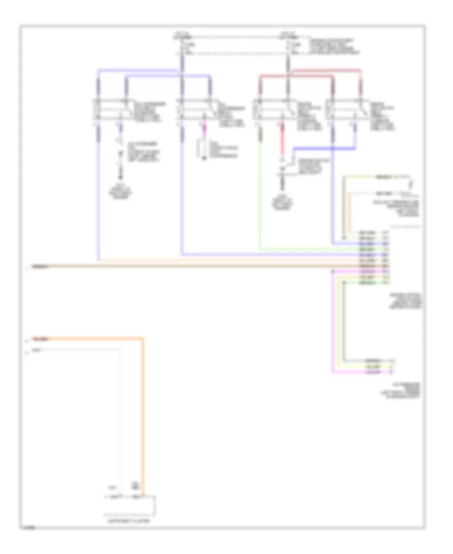
Automatic A/C Wiring Diagram (2 of 2) for Volvo V40 2001
List of elements for Automatic A/C Wiring Diagram (2 of 2) for Volvo V40 2001:
- A/c compressor relay (in eng compt fuse & relay box)
- A/c condenser fan (in front of eng compt, beside left headlight)
- A/c condenser fan relay (in engine compt fuse & relay box)
- A/c pressure sensor (left front corner of engine compt)
- Air conditioning (a/c) compressor
- B13
- B15
- Coolant temperature sensor (engine) (left front of engine)
- Engine compartment fuse & relay box (in left rear corner of engine compartment)
- Engine control module (ecm) (behind lower center of dash)
- Engine cooling fan motor (in front of eng compt)
- Engine cooling fan relay (speed 1) (in engine compt fuse & relay box)
- Engine cooling fan relay (speed 2) (in engine compt fuse & relay box)
- Fuse 15a
- Fuse 30a
- G100 (front of left front fender)
- G101 (front of right front fender)
- Hot at all times
- Instrument cluster
- Red