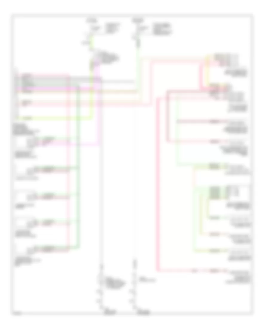
COMPUTER DATA LINES
Computer Data Lines for Infiniti Q45 2002
List of elements for Computer Data Lines for Infiniti Q45 2002:
- (left kick panel)
- Body computer module (bcm) (left kick panel)
- Can h
- Can l
- Combination meter
- Data line a1
- Data line a2
- Data line a3
- Data link connector (left side of dash, near hood lock release handle)
- Drivers door module
- Drivers seat control unit (under drivers seat)
- Drivers side door mirror control unit (in drivers door)
- Engine control module (ecm) (behind glove box)
- F8 (left side of engine)
- Front passenger door control unit
- Front passenger door mirror control unit (in front passenger door)
- Fuse 58 10a
- Fuse 6 10a
- Fuse block (j/b) no. 1
- Fuse, fusible link and relay block (right front of engine compt)
- Hot at all times
- Hot in on or start
- Joint connector 11 (top center of dash, taped to harness)
- Joint connector 15 (behind upper right side of dash)
- Joint connector 29
- Joint connector 5 (upper left side of dash, taped to harness)
- Joint connector 8 (behind upper left side of dash)
- Kline
- Left rear door control unit
- Local data line
- M25 (left side of dash)
- Pnk
- Right rear door control unit
- Steering angle sensor
- Transmission control module (tcm) (behind glove box)
- Vdc/tcs/abs control unit (right kick panel)
 Dansk
Dansk Deutsch
 Ελληνικά
 English
 English
 Español
 Suomi
Suomi Français
 Français
 עברית
עברית Hrvatski
 Magyar
 Italiano
 日本語
日本語 한국어
한국어 Nederlands
 Polski
 Português
 Português
 Română
 Русский
 Slovenčina
 Slovenščina
 Svenska
 Türkçe
 中文 (中国)
 Čeština