
 Dansk
Dansk Deutsch
 Ελληνικά
 English
 English
 Español
 Suomi
Suomi Français
 Français
 עברית
עברית Hrvatski
 Magyar
 Italiano
 日本語
日本語 한국어
한국어 Nederlands
 Polski
 Português
 Português
 Română
 Русский
 Slovenčina
 Slovenščina
 Svenska
 Türkçe
 中文 (中国)

HORN
Horn Wiring Diagram for Audi A6 Prestige Quattro 2013
List of elements for Horn Wiring Diagram for Audi A6 Prestige Quattro 2013:
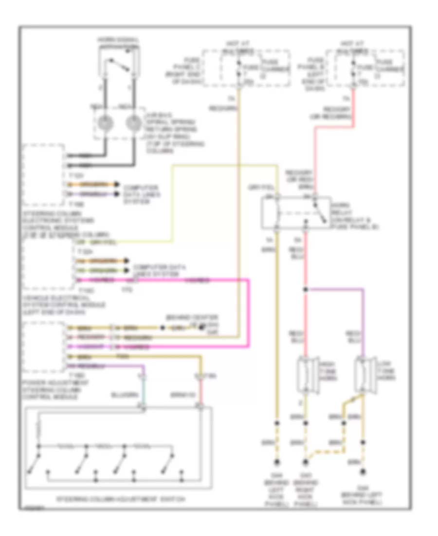

SHIFT INTERLOCKRADIOTRANSMISSIONSTARTING/CHARGINGWARNING SYSTEMSTRUNK, TAILGATE, FUEL DOORSUPPLEMENTAL RESTRAINTSAIR CONDITIONINGWIPER/WASHERANTI-THEFTBODY CONTROL MODULESDEFOGGERSCOMPUTER DATA LINESCRUISE CONTROLCOOLING FANANTI-LOCK BRAKESELECTRONIC POWER STEERINGENGINE PERFORMANCEELECTRONIC SUSPENSIONEXTERIOR LIGHTSHORNINTERIOR LIGHTSMEMORY SYSTEMSHEADLIGHTSGROUND DISTRIBUTIONPOWER DOOR LOCKSPOWER DISTRIBUTIONNAVIGATIONINSTRUMENT CLUSTERPOWER MIRRORSPOWER WINDOWSPOWER SEATSPOWER TOP/SUNROOF