ANTI-LOCK BRAKES
Anti-lock Brake Wiring Diagrams for Ford Cab & Chassis F350 1994
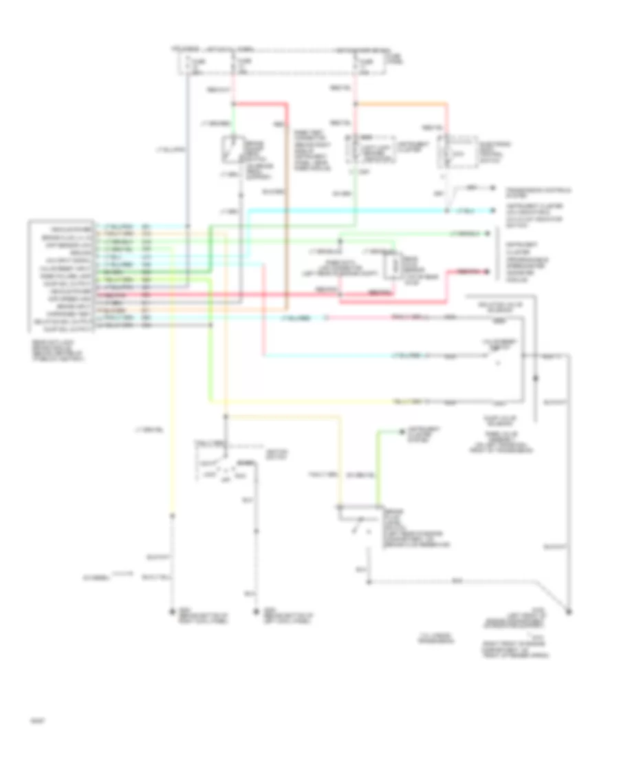
List of elements for Anti-lock Brake Wiring Diagrams for Ford Cab & Chassis F350 1994:
- engine compartment on radiator support)
- (4x4 indicator &
- (behind right side of instrument panel, near rabs module)
- (di diesel)
- (left front of
- (on brake pedal support)
- (programmable
- (top of rear axle)
- 4x4
- 4x4 hi/low indicator
- 4x4 input signal
- 7.3l w/e4od transmission
- Acc
- Anti-lock brakes indicator
- Brake fluid level switch (left rear of engine compartment, on brake fluid reservoir)
- Brake fluid lvl in
- Brake input
- Brake on/off (boo) switch
- C250
- C251
- Cluster
- Compartment, on
- Diff sensor low
- Diff speed high
- Dump sol output
- Dump valve solenoid
- Electronic shift control switch
- Front of fender apron)
- Fuse 10a
- Fuse 15a
- Fuse 20a
- Fuse panel
- G101 (right front of engine
- G108
- G200 (behind bottom of left cowl panel)
- G203 (behind bottom of right cowl panel)
- Ground
- Hot at all times
- Hot in run
- Hot in start or run
- Ignition switch
- Instrument
- Instrument cluster
- Instrument cluster system
- Isolation sol output
- Isolation valve solenoid
- Kapr/rabs test
- Lock
- Module)
- Nca
- Odometer
- Off
- Rabs data link connector (left rear of engine compt)
- Rabs failure lamp
- Rabs test connector
- Rabs valve assembly (on left frame rail front of transmission)
- Rear anti-lock brake module (behind center of i/p below ashtray)
- Rear axle sensor
- Red
- Red/pnk
- Run
- Speedometer/
- Start
- Switch)
- Transmission controls system
- Valve reset input
- Valve reset switch
- Vehicle power
 Dansk
Dansk Deutsch
 Ελληνικά
 English
 English
 Español
 Suomi
Suomi Français
 Français
 עברית
עברית Hrvatski
 Magyar
 Italiano
 日本語
日本語 한국어
한국어 Nederlands
 Polski
 Português
 Português
 Română
 Русский
 Slovenčina
 Slovenščina
 Svenska
 Türkçe
 中文 (中国)
 Čeština