AIR CONDITIONING
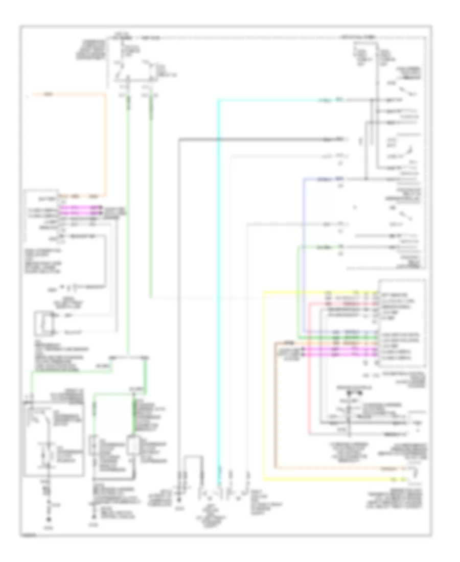
Automatic A/C Wiring Diagram (1 of 2) for Pontiac Bonneville GXP 2005
 https://portal-diagnostov.com/license.html
Automotive Electricians Portal FZCO
Automotive Electricians Portal FZCO
https://portal-diagnostov.com/license.html
https://portal-diagnostov.com/license.html
Automotive Electricians Portal FZCO
Automotive Electricians Portal FZCO
List of elements for Automatic A/C Wiring Diagram (1 of 2) for Pontiac Bonneville GXP 2005:
- (2 cm from instrument cluster breakout)
- (23.5 cm from c204 breakout)
- (in hvac harn, 30 cm from c204 breakout) s221
- (in hvac harness, 36.5 cm from c204 breakout)
- (in i/p harness, 35 cm from instrument cluster breakout)
- (mounted on right front of blower motor) blower motor control processor
- 5v ref
- A10
- A11
- A12
- Amb air temp sig
- Amb light sens
- Ambient air temperature sensor (center of engine compt, forward of radiator)
- Backlight
- Bat pos volt
- Battery
- Blower motor (under right side of dash, above sound insulator)
- Blwr mtr gnd
- Blwr sp cntrl
- Blwr volt
- C1 a1
- C11
- C12
- C13
- C3 e11
- Class 2 serial
- Clock sig
- Computer data lines system
- D11
- D12
- D16
- Data sig
- Dim fuse 38 10a
- Drvr sun ld sens
- G200
- G201
- Gnd
- Ground
- Headlights system
- Hot at all times
- Hot in on
- Hvac batt fuse 37 10a
- Hvac blo fuse 2 30a
- Hvac control module (in center of dash)
- Hvac fuse 33 10a
- Ign 3 rr fuse 34 10a
- Ign 3 volt
- Ign 3 voltage
- In air temp sig
- Inside air temperature sensor (on dash, right of steering column)
- Instrument panel integration module (behind left side of dash)
- Interior lights system
- Left air temp dr
- Left air temperature actuator (on top left side of hvac assembly)
- Lft air temp dr
- Low left temp sig
- Low ref
- Low rt temp sig
- Lower left air temperature sensor (behind left air discharge vent)
- Lower right air temperature sensor (behind right air discharge vent)
- Mode actuator (under left side of dash, on left side of hvac assembly)
- Mode dr ctrl
- Mode dr pos sens
- Mtr ctrl
- Mtr spd ctrl
- Nca
- Pass sun ld sens
- Rear fuse block (under left rear seat)
- Recirc dr ctrl
- Recirc dr pos
- Recirculation actuator (right side of dash, right of blower motor)
- Right air temp dr
- Right air temperature actuator (behind glove box, on right side of hvac assembly)
- Rt air temp dr
- S203 (in i/p harness, 6.5 cm from ipm breakout)
- S204
- S205
- S222
- S253 (in i/p wiring harness, 13 cm from turn signal hazard flasher module)
- Solid state
- Sp200 (left front door pillar)
- Sp201 (on right front door pillar)
- Sp201 (right front door pillar)
- Sunload sensor assembly (on top center of dash)
- Tan
- Up left temp sig
- Up rt temp sig
- Upper left air temperature sensor (behind left air discharge vent)
- Upper right air temperature sensor (behind right air discharge vent)
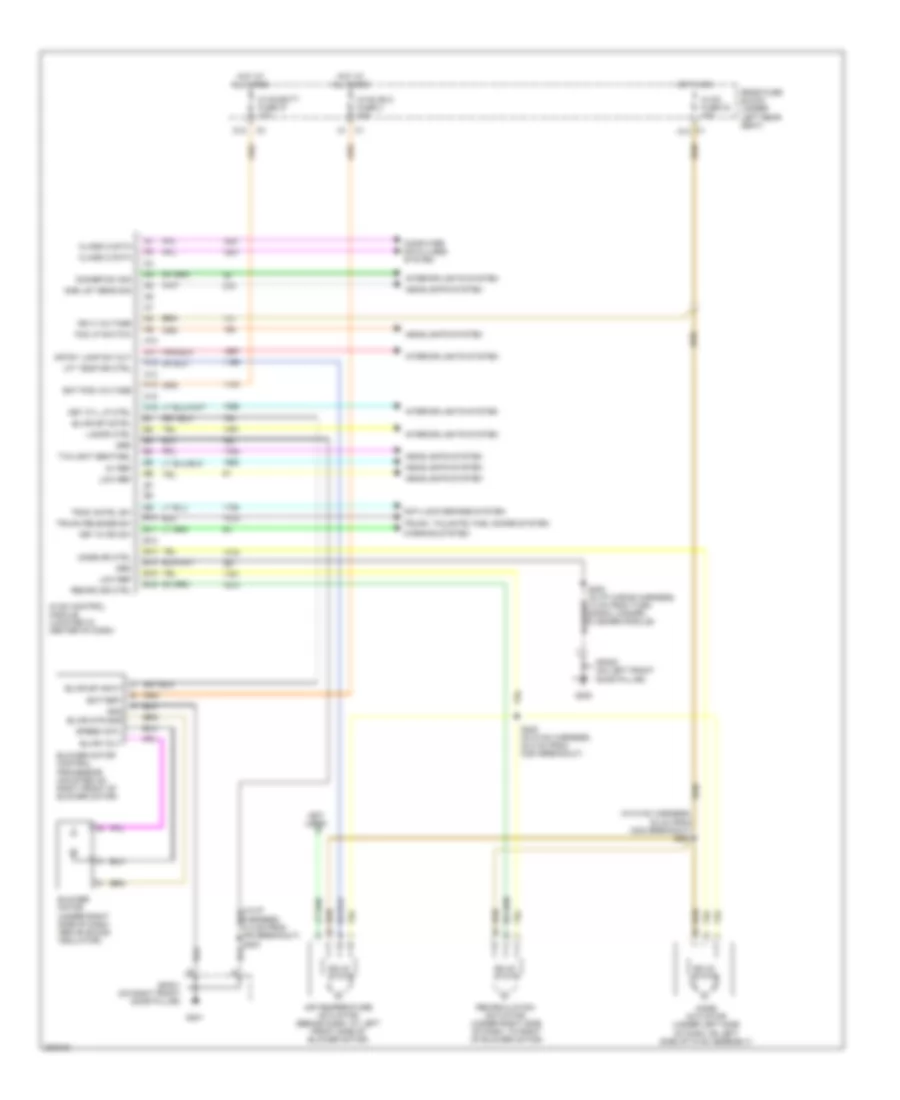
Automatic A/C Wiring Diagram (2 of 2) for Pontiac Bonneville GXP 2005
List of elements for Automatic A/C Wiring Diagram (2 of 2) for Pontiac Bonneville GXP 2005:
- ( in engine harness, 6.5 cm from idle air control valve connector breakout)
- (front of a/c compressor) a/c compressor clutch
- (high speed) coolfan 2 relay 37
- (in engine harness, 9.5 cm from pcm connector) s105
- 3.8l
- 3.8l 4.6l
- 4.6l
- 474 (or 2700)
- 5v ref
- 808 (or 2751)
- A/c clu fuse 26 15a
- A/c clu relay 32
- A/c compressor clutch (on front of a/c compressor)
- A/c compressor clutch diode (on wiring harness, near a/c compressor)
- A/c compressor clutch solenoid
- A/c compressor temperature switch
- A/c refrigerant low temperature sensor (4.6l) (rear center of engine, on high pressure line junction block to evaporator core)
- A/c refrigerant pressure sensor (behind a/c compressor, on a/c line)
- A10
- A11
- A11 class 2 serial a12 class 2 serial a6
- A12
- B10
- B11
- Battery
- C10
- C11
- Class 2 serial
- Clutch rly ctrl
- Computer data lines system
- Cool fan 1 fuse 47 30a
- Cool fan 2 fuse 46 30a
- Coolfan 1 relay (low speed)
- Coolfan s/p relay 39 (series/parallel)
- D10
- Dash integration module (dim) (4.6l) (behind right side of dash, under sound insulator)
- E10
- E11
- Ect sens sig
- Engine controls system
- Engine coolant temperature (ect) sensor (3.8l: on rear of engine, near thermostat housing) (4.6l: below throttle body)
- F11
- G10
- G103
- G105
- G108
- G11
- G200
- Gnd
- High spd fan cntrl
- Hot at all times
- Hot in on
- Left cooling fan (at left front of engine compt)
- Lo ref
- Low ref
- Low spd fan cntrl
- Nca
- Powertrain control module (in air cleaner housing)
- Right cooling fan (at right front of engine compt)
- S106
- S109
- S130
- Sens sig
- Sensor signal
- Sp103 (in front of underhood fuse block)
- Sp105 (below ignition control module)
- Sp200 (on left front door pillar)
- T10
- T11
- Underhood fuse block (right front side of engine compartment)
- V10
- V11
Manual A/C Wiring Diagram (1 of 2) for Pontiac Bonneville GXP 2005
List of elements for Manual A/C Wiring Diagram (1 of 2) for Pontiac Bonneville GXP 2005:
- (in hvac harness, 30 cm from c204 breakout) s221
- (in i/p harness, 6.5 cm from ipm breakout) s203
- (not used)
- 5v ref
- A10
- A11
- A12
- A13
- A14
- A15
- A16
- Air temperature actuator (behind dash, at left front side of blower motor)
- Amb lgt sens sig
- Anti-lock brakes system
- B10
- B11
- B12
- B13
- B14
- B15
- B16
- Bat pos voltage
- Battery
- Blower motor (under right side of dash, above sound insulator)
- Blower motor control processor (mounted on right front of blower motor)
- Blwr mtr gnd
- Blwr sp cntrl
- Blwr sp input
- Blwr volt
- C1 a10
- Class 2 data
- Computer data lines system
- Crtsy lamp sw out
- D12
- Dimmer sw sig
- Fog lp switch
- G200
- G201
- Gnd
- Grd
- Headlights system
- Hot at all times
- Hot in on
- Hvac batt fuse 37 10a
- Hvac blo fuse 2 30a
- Hvac control module (located in center of dash)
- Hvac fuse 33 10a
- Ign 3 voltage
- Interior lights system
- Key cyl lp ctrl
- Key in ign sw
- Lamps ctrl
- Lft temp dr ctrl
- Low ref
- Mode actuator (under left side of dash, on left side of hvac assembly)
- Mode dr ctrl
- Rear fuse block (under left rear seat)
- Recirc dr ctrl
- Recirculation actuator (under right side of dash, to right of blower motor)
- S222 (in hvac harness, 23.5 cm from c204 breakout)
- S253 (in i/p wiring harness, 13 cm from turn signal hazard flasher module)
- Solid state
- Sp200 (on left front door pillar)
- Sp201 (on right front door pillar)
- Speed cntl
- Trac cntrl sw
- Trunk release sw
- Trunk, tailgate, fuel doors system
- Twilight sentinel
- Warning system
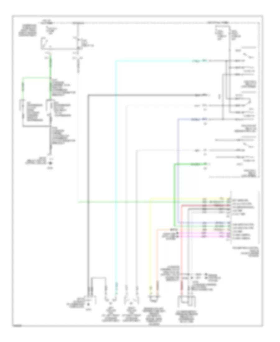
Manual A/C Wiring Diagram (2 of 2) for Pontiac Bonneville GXP 2005
List of elements for Manual A/C Wiring Diagram (2 of 2) for Pontiac Bonneville GXP 2005:
- (in engine harness, 6.5 cm
- 5 volt ref
- A/c clu fuse 15a
- A/c clu relay 32
- A/c clutch ctrl
- A/c compressor clutch (on front of a/c compressor)
- A/c compressor clutch diode (on wiring harness, near a/c compressor)
- A/c refrigerant pressure sensor (behind a/c compressor, on a/c line)
- A/c sensor signal
- A10
- A11
- B10
- B11
- C10
- C11
- Class 2 serial
- Computer data lines system
- Cool fan 1 fuse 47 30a
- Cool fan 2 fuse 46 30a
- Coolfan 1 relay (low speed)
- Coolfan 2 relay 37 (high speed)
- Coolfan s/p relay 39 (series/parallel)
- D10
- E10
- E11
- Ect sens sig
- Engine controls system
- Engine coolant temperature (ect) sensor (on rear of
- Engine, near thermostat housing)
- F11
- From idle air control valve connector breakout)
- G10
- G103
- G105
- G11
- High spd fan ctrl
- Hot at all times
- Hot in on
- Left cooling fan (at left front of engine compartment)
- Low ref
- Low spd fan ctrl
- Powertrain control module (in air cleaner housing)
- Right cooling fan (at right front of engine compartment)
- S106
- S108 (in engine harnes, 18 cm from a/c compressor clutch connector breakout)
- S109
- Sp103 (in front of underhood fuse block)
- Sp105 (below ignition control module)
- T10
- T11
- Underhood fuse block (right front side of engine compartment)
- V10
- V11
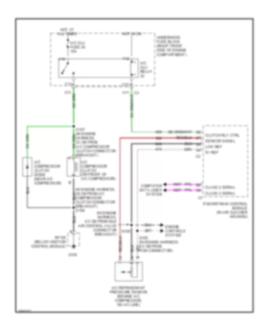
3.8L VIN K
3.8L VIN K, Compressor Wiring Diagram for Pontiac Bonneville GXP 2005
List of elements for 3.8L VIN K, Compressor Wiring Diagram for Pontiac Bonneville GXP 2005:
- (in engine harness, 18 cm from a/c compressor clutch connector breakout) s108
- (in engine harness, 6.5 cm from idle air control valve connector breakout)
- 5v ref
- A/c clu fuse 26 15a
- A/c clu relay
- A/c compressor clutch (on front of a/c compressor)
- A/c compressor clutch diode (near a/c compressor)
- A/c refrigerant pressure sensor (behind a/c compressor, on a/c line)
- Class 2 serial
- Clutch rly ctrl
- Computer data lines system
- Engine controls system
- G105
- Hot at all times
- Hot in on
- Low ref
- Powertrain control module (in air cleaner housing)
- S106
- Sensor signal
- Sp105 (below ignition control module)
- T10
- T11
- Underhood fuse block (right front side of engine compartment)
- V10
- V11
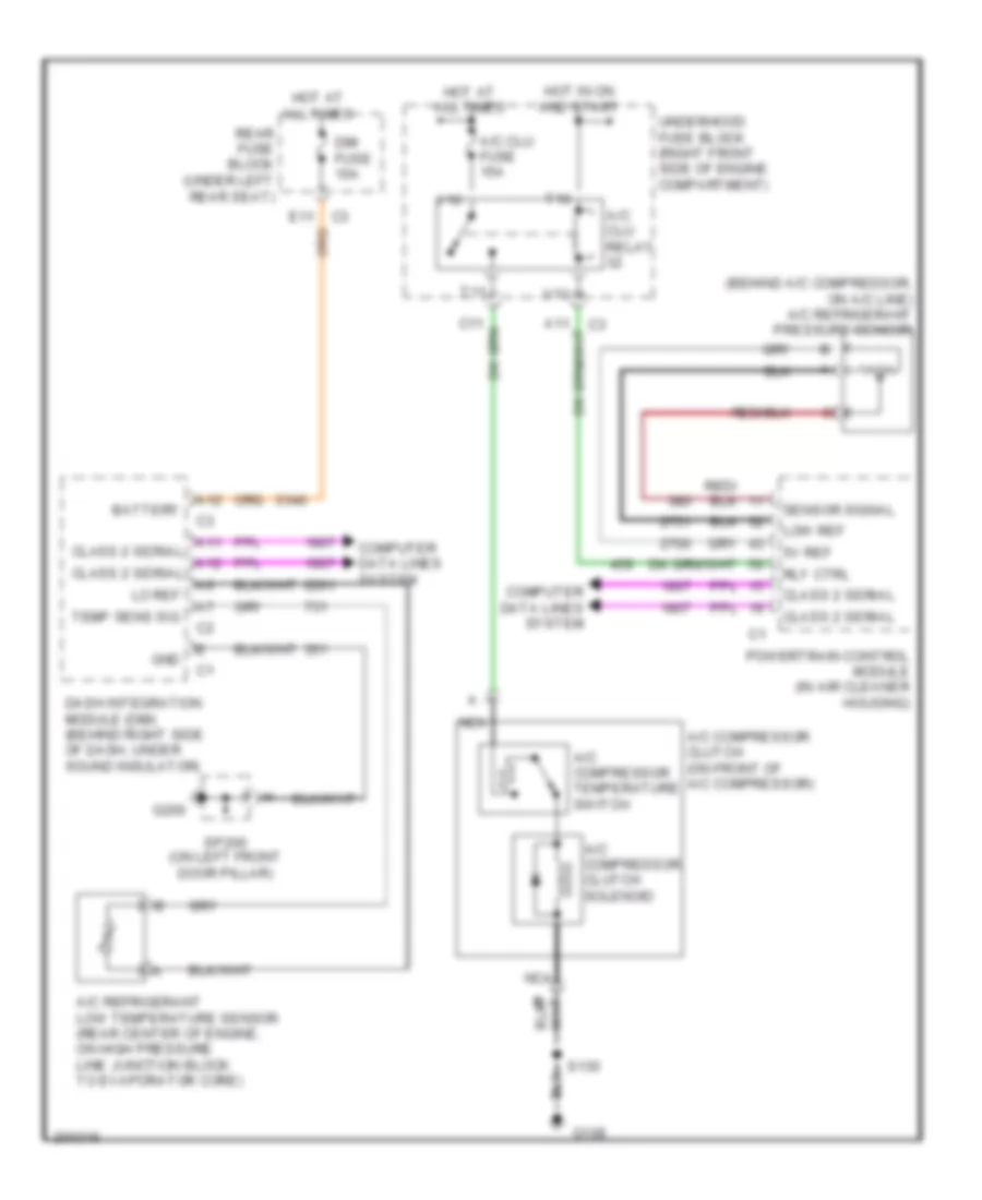
4.6L VIN A
4.6L VIN A, Compressor Wiring Diagram for Pontiac Bonneville GXP 2005
List of elements for 4.6L VIN A, Compressor Wiring Diagram for Pontiac Bonneville GXP 2005:
- (behind a/c compressor, on a/c line) a/c refrigerant pressure sensor
- 5v ref
- A/c clu fuse 15a
- A/c clu relay
- A/c compressor clutch (on front of a/c compressor)
- A/c compressor clutch solenoid
- A/c compressor temperature switch
- A/c refrigerant low temperature sensor (rear center of engine, on high pressure line junction block to evaporator core)
- A11 class 2 serial
- A12
- A12 class 2 serial
- Battery
- C3 e11
- Class 2 serial
- Computer data lines system
- Dash integration module (dim) (behind right side of dash, under sound insulator)
- Dim fuse 10a
- G108
- G200
- Gnd
- Hot at all times
- Hot in on and start
- Lo ref
- Low ref
- Nca
- Powertrain control module (in air cleaner housing)
- Rear fuse block (under left rear seat)
- Rly ctrl
- S130
- Sensor signal
- Sp200 (on left front door pillar)
- T10
- T11
- Temp sens sig
- Underhood fuse block (right front side of engine compartment)
- V10
- V11

 Dansk
Dansk Deutsch
 Ελληνικά
 English
 English
 Español
 Suomi
Suomi Français
 Français
 עברית
עברית Hrvatski
 Magyar
 Italiano
 日本語
日本語 한국어
한국어 Nederlands
 Polski
 Português
 Português
 Română
 Русский
 Slovenčina
 Slovenščina
 Svenska
 Türkçe
 中文 (中国)