AIR CONDITIONING
A/C Wiring Diagram for Pontiac Firebird Formula 1998
 https://portal-diagnostov.com/license.html
Automotive Electricians Portal FZCO
Automotive Electricians Portal FZCO
https://portal-diagnostov.com/license.html
https://portal-diagnostov.com/license.html
Automotive Electricians Portal FZCO
Automotive Electricians Portal FZCO
List of elements for A/C Wiring Diagram for Pontiac Firebird Formula 1998:
- (3.8l: eng harn, 3 cm back from generator breakout) (5.7l: eng harn, 17 cm back from a/c compressor clutch conn)
- (3.8l: eng harn, 7.5 cm from inj 4 breakout) (5.7l: eng harn, 33 cm back from a/c comp clutch breakout)
- (3.8l: eng harn, at generator breakout) (5.7l: eng harn, 20 cm back from a/c clutch breakout)
- (5.7l on lower left side of engine)
- (eng harn, at a/c refrigerant pressure sensor breakout)
- (forward lamp harn)
- (forward lamp harn, near right radiator support)
- (in underhood electrical center 1)
- (near top left side of the radiator support)
- +5v
- 0.31 ohm total
- 0.61 ohm
- 1.85 ohm
- 3.8l
- 407 (or 720)
- 5.7l
- A/c clutch diode (1 amp)
- A/c compressor clutch
- A/c compressor relay (in underhood electrical center 2)
- A/c refrigerant pressure sensor (above right front wheelhouse, on refrigerant line)
- A/c request
- A/c-cruise fuse (mini) 15a
- Bi-lv
- Blend
- Blower motor
- Blower motor relay (on inflatable restraint dash module bracket)
- Blower resistor (in hvac module)
- Blower switch
- C 1995 vftc
- C tan
- Center 2
- Clutch status
- Compressor ctrl
- Cool fan fuse (maxi) 40a
- Cooling fan fuse (mini) 10a
- D10
- Def
- Ect sensor input
- Engine coolant temperature sensor (3.8l: below throttle body)
- Engine cooling fan relay 1
- Engine cooling fan relay 2 (in underhood electrical center 1)
- Engine cooling fan relay 3 (in underhood electrical center 1)
- Fan rly 1 control
- Fan rly 2 & 3 control
- G108
- G112 (left side of engine)
- G200 (left kick panel)
- G203 (right kick panel)
- Hot at all times
- Hot in run
- Hot in run, bulb test or start
- Htr
- Htr/ def
- Htr/def
- Hvac control (blower switch contacts are make before break contacts)
- Hvac fuse 6 20a
- I/p 1 fuse (maxi) 40a
- I/p fuse block
- Interior lights system
- Left engine cooling fan
- Max
- Nca
- Norm
- Off
- Pnk
- Powertrain control module (in engine compt, rear of right strut tower)
- Red
- Right engine cooling fan
- S105
- S114
- S115
- S165 (forward lamp harn, 7cm from pnk underhood electrical center 2 breakout)
- S166
- S169 (forward lamp harn, 6 cm into underhood electrical center 1 breakout)
- S179
- S216 (i/p harn, 10 cm from i/p cluster breakout)
- S248 (i/p harn, 2 cm from radio connectors breakout)
- Selector switch
- Sensor ground
- Sensor sig
- Tan
- Underhood electrical
- Underhood electrical center 1
- Vent
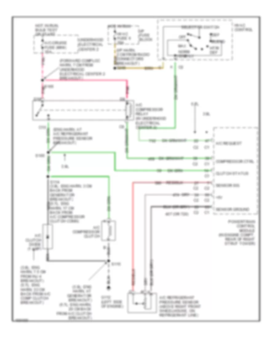
Compressor Wiring Diagram for Pontiac Firebird Formula 1998
List of elements for Compressor Wiring Diagram for Pontiac Firebird Formula 1998:
- (3.8l: eng harn, 7.5 cm from inj 4 breakout) (5.7l: eng harn, 33 cm back from a/c comp clutch breakout)
- (3.8l: eng harn, at generator breakout) (5.7l: eng harn, 20 cm back from a/c clutch breakout)
- (eng harn, at a/c refrigerant pressure sensor breakout)
- (forward comploc harn, 7 cm from underhood electrical center 2 breakout)
- +5v
- 3.8l
- 407 (or 720)
- 5.7l
- A/c clutch diode (1 amp)
- A/c compressor clutch
- A/c compressor relay (in underhood electrical center 2)
- A/c refrigerant pressure sensor (above right front wheelhouse, on refrigerant line)
- A/c request
- A/c-cruise fuse (mini) 15a
- Bi-lv
- Blend
- Center 2
- Clutch status
- Compressor ctrl
- D10
- Def
- G112 (left side of engine)
- Hot in run
- Hot in run, bulb test or start
- Htr/ def
- Hvac control
- Hvac fuse 6 20a
- I/p fuse block
- Max
- Nca
- Norm
- Off
- Pnk
- Powertrain control module (in engine compt, rear of right strut tower)
- S105
- S114 (3.8l: eng harn, 3 cm back from generator breakout) (5.7l: eng harn, 17 cm back from a/c compressor clutch conn)
- S115
- S165 pnk
- Selector switch
- Sensor ground
- Sensor sig
- Underhood electrical
- Vent

 Dansk
Dansk Deutsch
 Ελληνικά
 English
 English
 Español
 Suomi
Suomi Français
 Français
 עברית
עברית Hrvatski
 Magyar
 Italiano
 日本語
日本語 한국어
한국어 Nederlands
 Polski
 Português
 Português
 Română
 Русский
 Slovenčina
 Slovenščina
 Svenska
 Türkçe
 中文 (中国)