STARTING/CHARGING
2.0L TURBO
2.0L Turbo, Charging Wiring Diagram for Saab 9-3 Turbo X 2008
 https://portal-diagnostov.com/license.html
Automotive Electricians Portal FZCO
Automotive Electricians Portal FZCO
https://portal-diagnostov.com/license.html
https://portal-diagnostov.com/license.html
Automotive Electricians Portal FZCO
Automotive Electricians Portal FZCO
List of elements for 2.0L Turbo, Charging Wiring Diagram for Saab 9-3 Turbo X 2008:
- (or nca)
- B16
- Battery
- G2 (on side of left-hand structural member on connector console)
- G25 (on transmission)
- Generator
- Power distribution system
- Red
- Starter motor
- Trionic engine control module (front of engine)
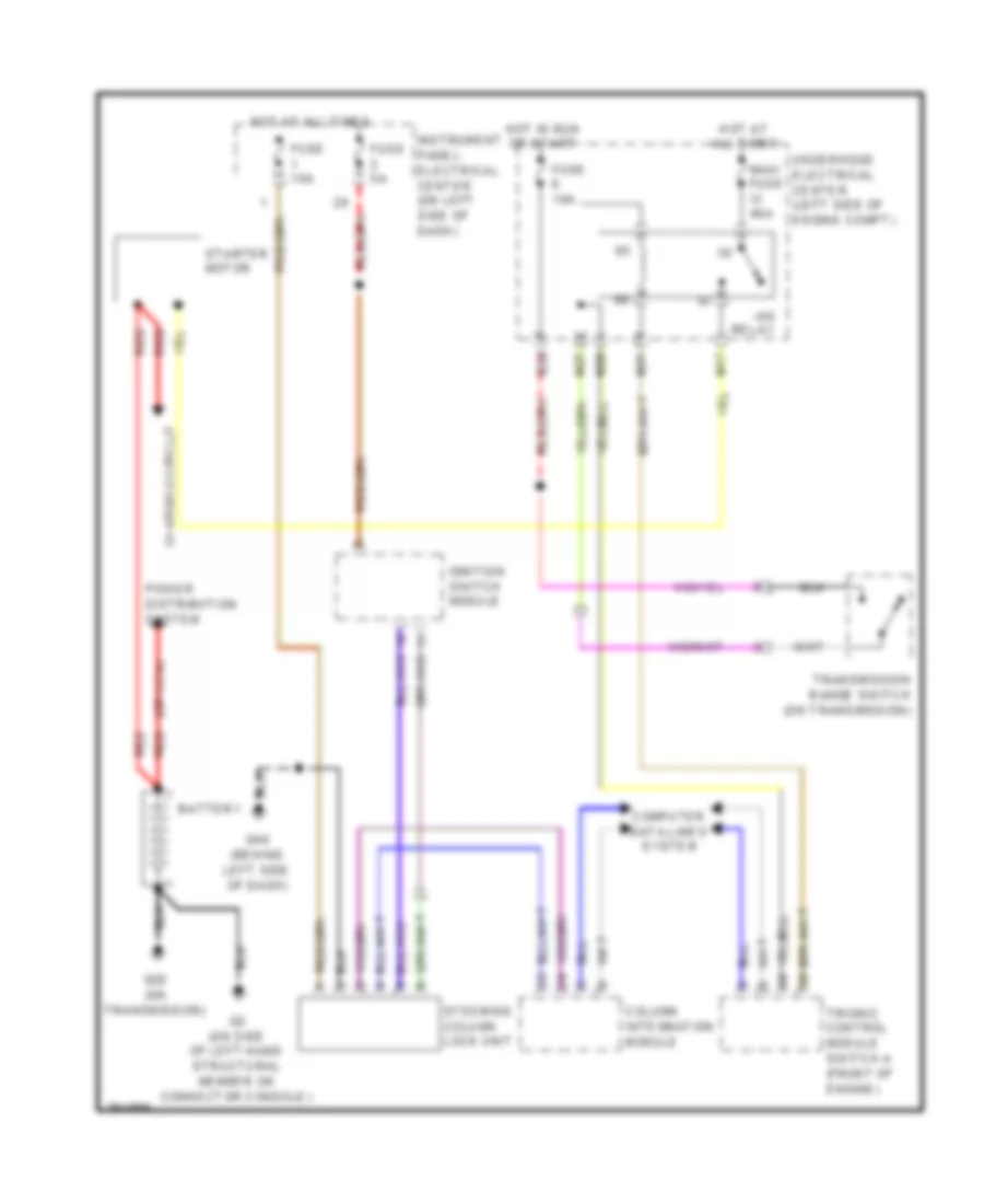
2.0L Turbo, Starting Wiring Diagram, A/T for Saab 9-3 Turbo X 2008
List of elements for 2.0L Turbo, Starting Wiring Diagram, A/T for Saab 9-3 Turbo X 2008:
- (or nca)
- +50 relay
- B20
- Battery
- Charging circuit
- Column integration module
- Computer data lines system
- Fuse 10a
- Fuse 15a
- Fuse 5a
- G2 (on side of left-hand structural member on connector console)
- G25 (on transmission)
- G40 (behind left side of dash)
- Hot at all times
- Hot in run or start
- Ignition switch module
- Instrument panel electrical center (on left side of dash)
- M17
- M21
- M27
- M28
- Maxi fuse 40a
- Power distribution system
- Red
- Starter motor
- Steering column lock unit
- Transmission range switch (on transmission)
- Trionic control module switch a (front of engine)
- Underhood electrical center (left side of engine compt)
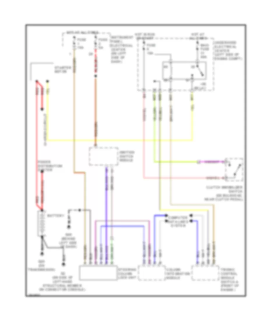
2.0L Turbo, Starting Wiring Diagram, M/T for Saab 9-3 Turbo X 2008
List of elements for 2.0L Turbo, Starting Wiring Diagram, M/T for Saab 9-3 Turbo X 2008:
- (or nca)
- +50 relay
- Battery
- Charging circuit
- Clutch immobilizer switch (on bulkhead, near clutch pedal)
- Column integration module
- Computer data lines system
- Fuse 10a
- Fuse 15a
- Fuse 5a
- G2 (on side of left-hand structural member on connector console)
- G25 (on transmission)
- G40 (behind left side of dash)
- Hot at all times
- Hot in run or start
- Ignition switch module
- Instrument panel electrical center (on left side of dash)
- M17
- M21
- M27
- M28
- Maxi fuse 40a
- Power distribution system
- Red
- Starter motor
- Steering column lock unit
- Trionic control module switch a (front of engine)
- Underhood electrical center (left side of engine compt)
2.8L TURBO
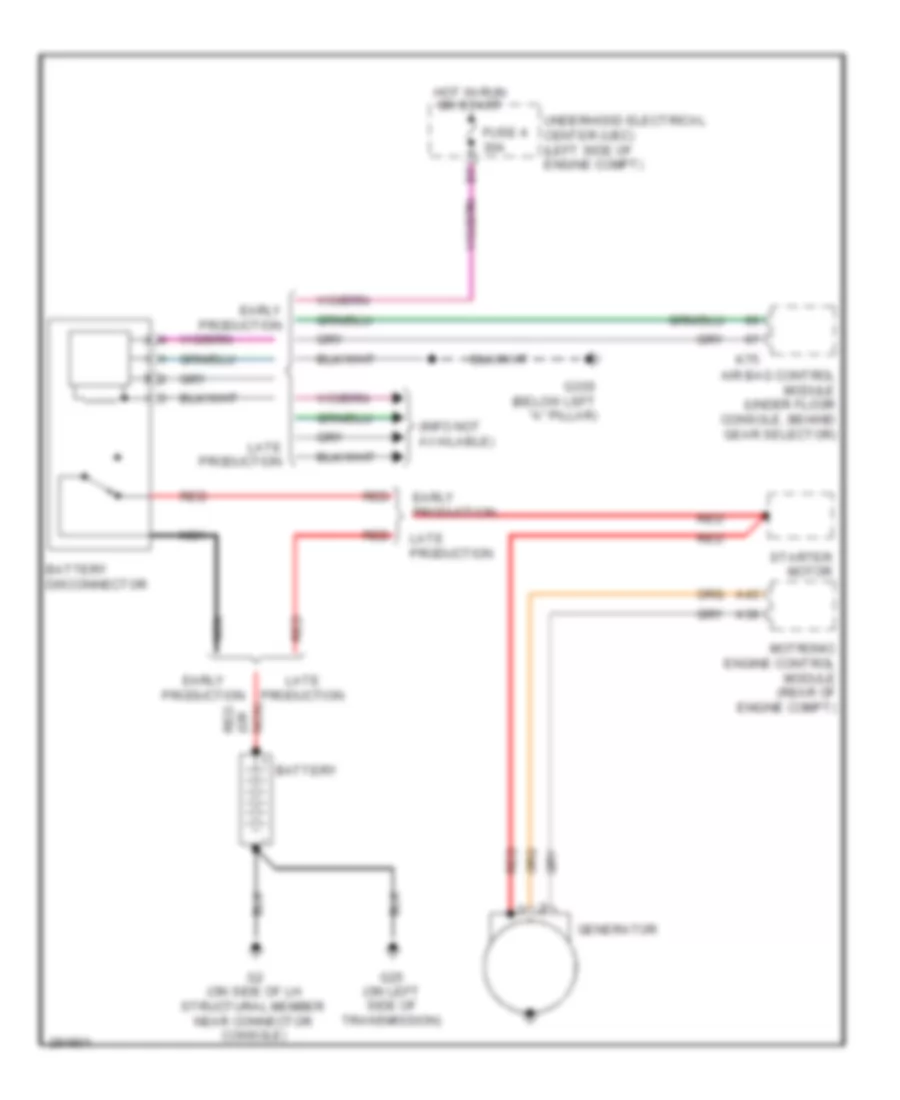
2.8L Turbo, Charging Wiring Diagram for Saab 9-3 Turbo X 2008
List of elements for 2.8L Turbo, Charging Wiring Diagram for Saab 9-3 Turbo X 2008:
- (info not available)
- A36
- A43
- Air bag control module (under floor console, behind gear selector)
- Battery
- Battery disconnector
- Early production
- Fuse 4 30a
- G2 (on side of lh structural member near connector console)
- G25 (on left side of transmission)
- G33s (below left "a" pillar)
- Generator
- Hot in run or start
- K75
- Late production
- Motronic engine control module (rear of engine compt)
- Nca
- Nca) (or red
- Red
- Starter motor
- Underhood electrical center (uec) (left side of engine compt)
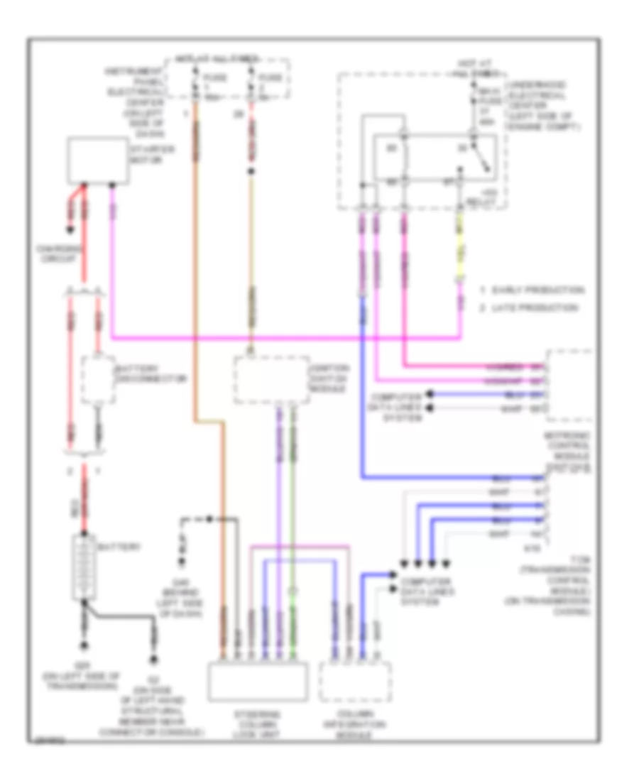
2.8L Turbo, Starting Wiring Diagram, A/T for Saab 9-3 Turbo X 2008
List of elements for 2.8L Turbo, Starting Wiring Diagram, A/T for Saab 9-3 Turbo X 2008:
- (or nca) red
- +50 relay
- Battery
- Battery disconnector
- Charging circuit
- Column integration module
- Computer data lines system
- Early production
- Fuse 15a
- Fuse 5a
- G2 (on side of left-hand structural member near connector console)
- G25 (on left side of transmission)
- G40 (behind left side of dash)
- Hot at all times
- Ignition switch module
- Instrument panel electrical center (on left side of dash)
- K16
- Late production
- M17
- M21
- M22
- M28
- Maxi fuse 40a
- Motronic control module switch b
- Nca
- Red
- Starter motor
- Steering column lock unit
- Tcm (transmission control module) (on transmission casing)
- Underhood electrical center (left side of engine compt)
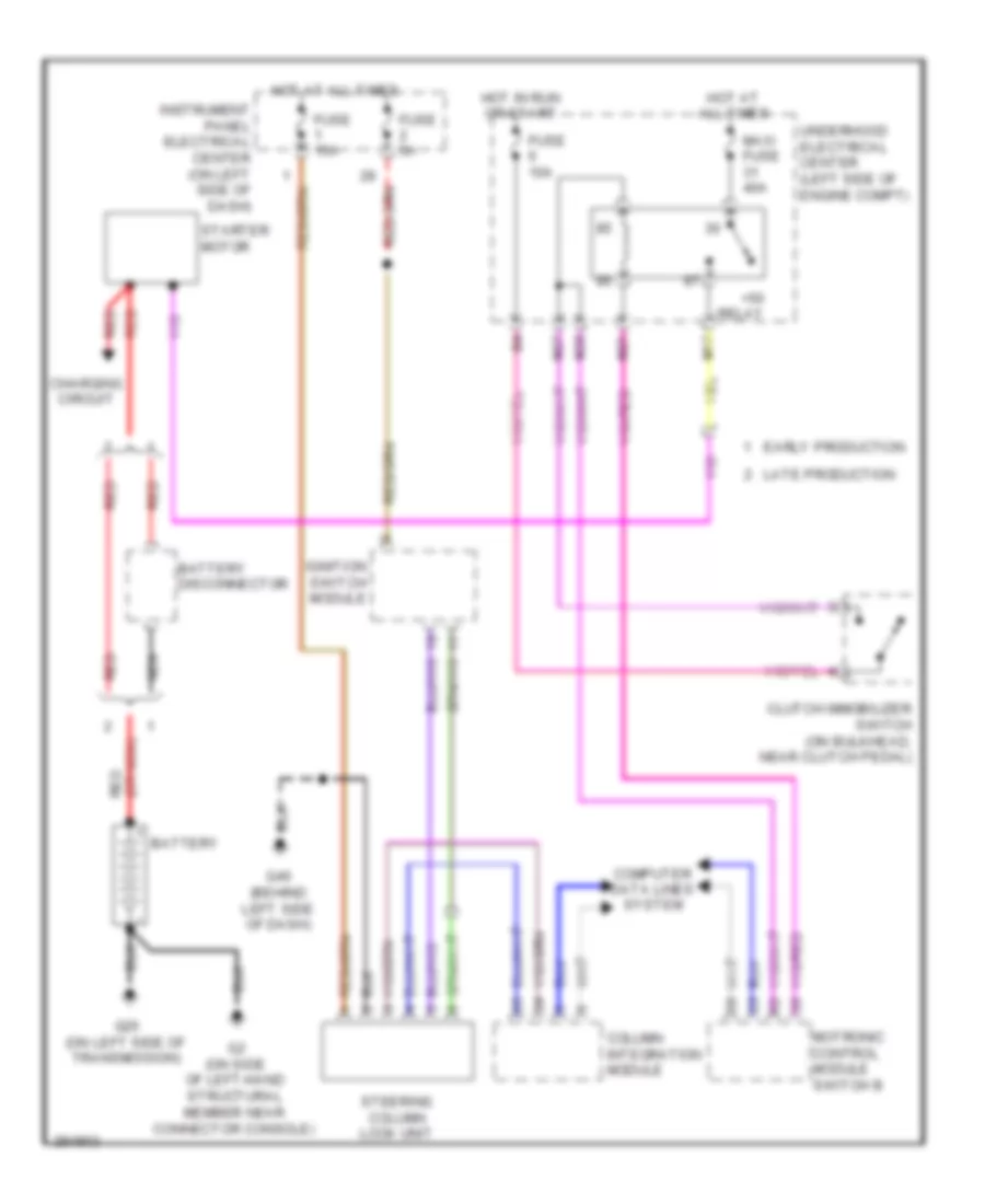
2.8L Turbo, Starting Wiring Diagram, M/T for Saab 9-3 Turbo X 2008
List of elements for 2.8L Turbo, Starting Wiring Diagram, M/T for Saab 9-3 Turbo X 2008:
- (or nca) red
- +50 relay
- Battery
- Battery disconnector
- Charging circuit
- Clutch immobilizer switch (on bulkhead, near clutch pedal)
- Column integration module
- Computer data lines system
- Early production
- Fuse 10a
- Fuse 15a
- Fuse 5a
- G2 (on side of left-hand structural member near connector console)
- G25 (on left side of transmission)
- G40 (behind left side of dash)
- Hot at all times
- Hot in run or start
- Ignition switch module
- Instrument panel electrical center (on left side of dash)
- Late production
- M17
- M21
- M27
- M28
- Maxi fuse 40a
- Motronic control module switch b
- Nca
- Red
- Starter motor
- Steering column lock unit
- Underhood electrical center (left side of engine compt)

 Dansk
Dansk Deutsch
 Ελληνικά
 English
 English
 Español
 Suomi
Suomi Français
 Français
 עברית
עברית Hrvatski
 Magyar
 Italiano
 日本語
日本語 한국어
한국어 Nederlands
 Polski
 Português
 Português
 Română
 Русский
 Slovenčina
 Slovenščina
 Svenska
 Türkçe
 中文 (中国)