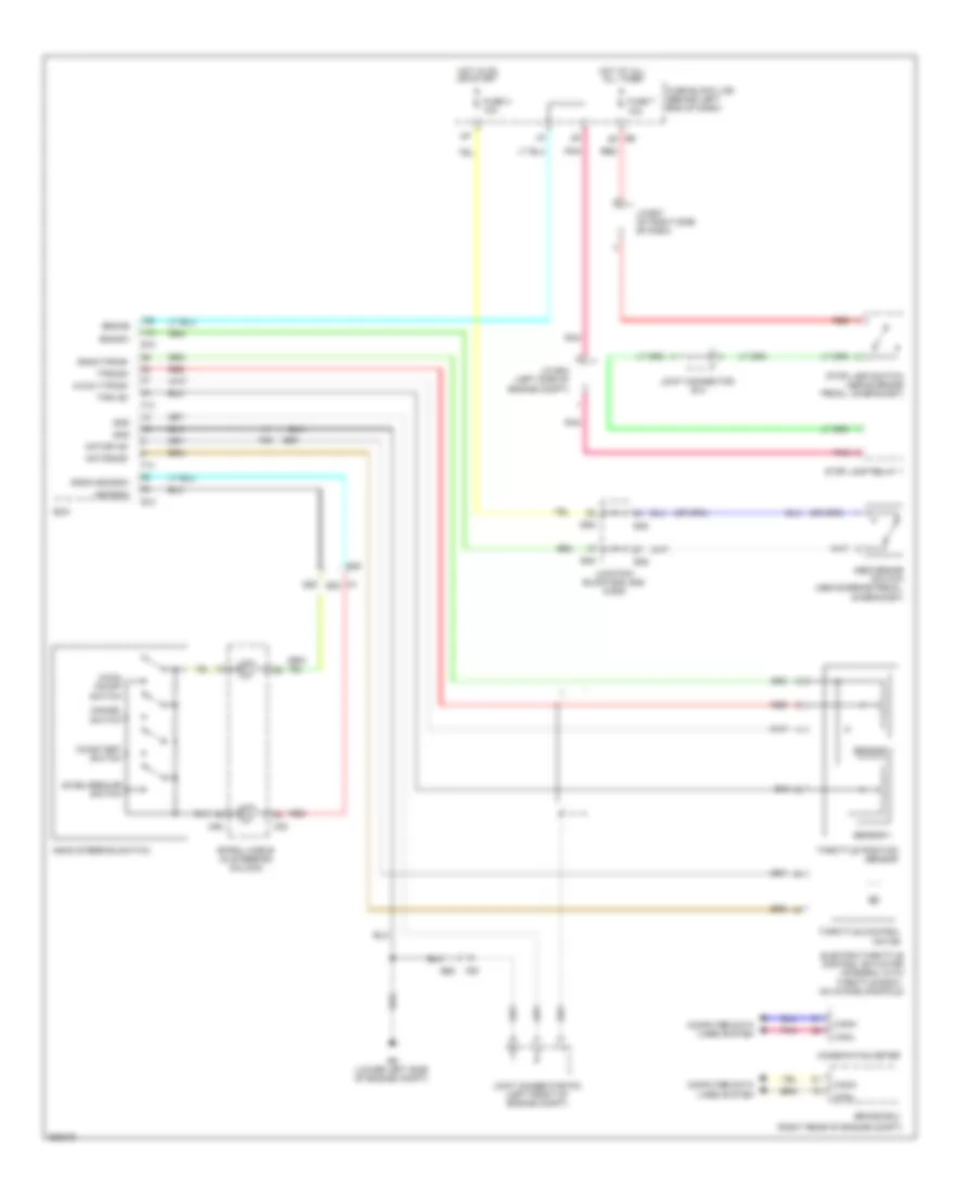
CRUISE CONTROL
Cruise Control Wiring Diagram, Except Hybrid for Nissan Altima Hybrid 2011
 https://portal-diagnostov.com/license.html
Automotive Electricians Portal FZCO
Automotive Electricians Portal FZCO
https://portal-diagnostov.com/license.html
https://portal-diagnostov.com/license.html
Automotive Electricians Portal FZCO
Automotive Electricians Portal FZCO
List of elements for Cruise Control Wiring Diagram, Except Hybrid for Nissan Altima Hybrid 2011:
- (2.5l)
- (2.5l) primary speed sensor
- (3.5l)
- (a/t)
- (above brake pedal, on bracket)
- (left front of engine compt) (2.5l) j/c f02 (3.5l) j/c f05
- (left front of engine compt) j/c f03
- (m/t)
- (or red)
- 10a
- 2.5l
- 2.5l california
- 2.5l except california
- 3.5l
- 55g
- 58g
- A/t
- Accel/resume switch
- Accelerator pedal position sensor
- Aps1
- Aps2
- Ascd brake switch (above brake pedal, on bracket)
- Ascd clutch switch
- Ascd steering switch
- Ascdsw
- Avcc1-aps1
- Avcc1-tps-b1
- Avcc2-aps2
- Bncsw
- Brake
- Can-h
- Can-l
- Cancel switch
- Coast/set switch
- Combination meter
- Computer data lines system
- Cruise ind
- Cvt unit (3.5l)
- Display)
- E10
- E11
- E30
- E31
- E32
- E44
- E45
- E46
- E6 8p
- E9 (lower left side of engine compt)
- Ecm (left front of engine compt)
- Electric throttle control actuator (2.5l: integral with throttle body, on intake manifold) (3.5l: integral with throttle body)
- F10
- F13
- F14
- F78
- F79
- F90
- F91
- Fuse
- Fuse 3 10a
- Fuse 7 10a
- Fuse block (j/b) (behind left end of dash)
- Gnd
- Gnda-aps1
- Gnda-aps2
- Gnda-ascdsw
- Gnda-tps-b1
- Hot at all all times
- Hot in on or start
- Hot w/ ignition relay 1 energized
- Intelligent power distribution module engine room (ipdm e/r) (left side of engine compt)
- J/c e07
- J/c e14
- Joint connector e06 (behind left end of dash)
- Joint connector f04 (3.5l) joint connector f01 (2.5l) (left front of engine compt)
- Junction block e44, e45 & e46
- M/t
- M30
- M88
- Main on/off switch
- Motor1-b1
- Motor2-b1
- Pnk
- Pri spd sens
- Primary speed sensor
- Red
- Sec spd
- Secondary speed sensor (on transaxle)
- Sens
- Sens gnd
- Sens pwr
- Sensor 1
- Sensor 2
- Shield
- Spiral cable (in steering column)
- Stop lamp relay 1 (a/t)
- Stop lamp switch
- Tcm (left front of engine compt)
- Throttle control motor
- Throttle position sensor
- Tps1-b1
- Tps2-b1
- Unified meter control unit (w/ information
- Vign
Cruise Control Wiring Diagram, Hybrid for Nissan Altima Hybrid 2011
List of elements for Cruise Control Wiring Diagram, Hybrid for Nissan Altima Hybrid 2011:
- (main) on/off switch
- (right rear of engine compt)
- 55g
- 58g
- Accel/resume switch
- Ascd brake switch (above brake pedal, on bracket)
- Ascd steering switch
- Ascdsw
- Avcc1-tps-b1
- Bncsw
- Brake
- Brake ecu
- Can-h
- Can-l
- Cancel switch
- Coast/set switch
- Combination meter
- Computer data lines system
- E10
- E30
- E45
- E46
- E48
- E6 8p
- E68
- E9 (lower left side of engine compt)
- Ecm
- Electric throttle control actuator (integral with throttle body, on intake manifold)
- F13
- F14
- F80
- Fuse 3 10a
- Fuse 7 10a
- Fuse block (j/b) (behind left end of dash)
- Gnd
- Gnda-ascdsw
- Gnda-tps-b1
- Hot at all all times
- Hot in on or start
- J/c e04 (left side of engine compt)
- J/c e07 (at right side of dash)
- Joint connector e14
- Joint connector f03 (left front of engine compt)
- Junction block e45, e46 & e48
- M30
- M88
- Motor1-b1
- Motor2-b1
- Pnk
- Red
- Sensor 1
- Sensor 2
- Spiral cable (in steering column)
- Stop lamp relay 1
- Stop lamp switch (above brake pedal, on bracket)
- Throttle control motor
- Throttle position sensor
- Tps1-b1
- Tps2-b1

 Dansk
Dansk Deutsch
 Ελληνικά
 English
 English
 Español
 Suomi
Suomi Français
 Français
 עברית
עברית Hrvatski
 Magyar
 Italiano
 日本語
日本語 한국어
한국어 Nederlands
 Polski
 Português
 Português
 Română
 Русский
 Slovenčina
 Slovenščina
 Svenska
 Türkçe
 中文 (中国)