DEFOGGERS
Defoggers Wiring Diagram for Mitsubishi Lancer ES 2009
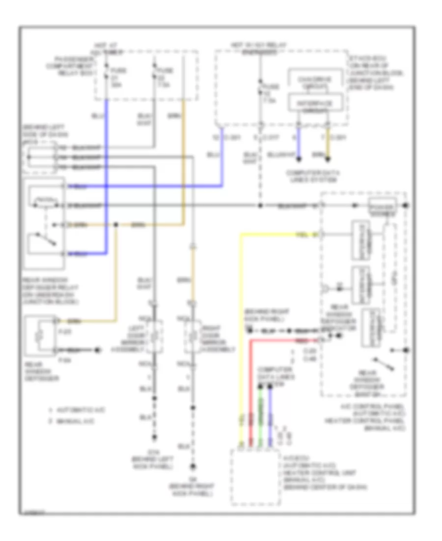
List of elements for Defoggers Wiring Diagram for Mitsubishi Lancer ES 2009:
- (behind left side of dash) j/c 3
- (behind right kick panel) g4
- A/c control panel (automatic a/c) heater control panel (manual a/c)
- A/c-ecu (automatic a/c) heater control unit (manual a/c) (behind center of dash)
- Automatic a/c
- C-20
- C-301
- C-317
- C-48
- Can drive circuit
- Computer data lines system
- Cpu
- Etacs-ecu (on rear of junction block, behind left end of dash)
- F-04
- F-25
- Fuse 30a
- Fuse 7.5a
- G14 (behind left kick panel)
- G4 (behind right kick panel)
- Hot at all times
- Hot w/ ig1 relay energized
- Interface circuit
- Left door mirror assembly
- Manual a/c
- Nca
- Passenger compartment relay box
- Power source
- Rear window defogger
- Rear window defogger indicator
- Rear window defogger relay (on underdash junction block)
- Rear window defogger switch
- Red
- Right door mirror assembly
 Dansk
Dansk Deutsch
 Ελληνικά
 English
 English
 Español
 Suomi
Suomi Français
 Français
 עברית
עברית Hrvatski
 Magyar
 Italiano
 日本語
日本語 한국어
한국어 Nederlands
 Polski
 Português
 Português
 Română
 Русский
 Slovenčina
 Slovenščina
 Svenska
 Türkçe
 中文 (中国)
 Čeština