DEFOGGERS
Defoggers Wiring Diagram for Nissan Maxima SL 2007
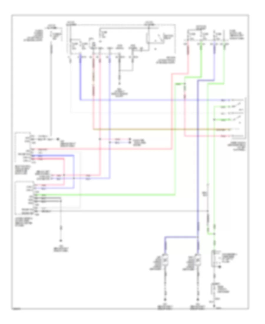
List of elements for Defoggers Wiring Diagram for Nissan Maxima SL 2007:
- (below left side of dash) data link connector
- + b301
- +ig
- - b351
- 15p
- B352
- Bat
- Body control module (bcm) (near fuse block (j/b))
- Can-h
- Can-l
- Computer
- Condenser-3 (near base of left "c" pillar)
- Cpu
- Data lines
- E119
- E121
- E124
- E24 (at right side of engine compt)
- E30
- Fuse & fusible link box (at left front of engine compt)
- Fuse 10a
- Fuse 15a
- Fuse 20a
- Fuse block (j/b) (behind left
- Fusible link f 50a
- Gnd
- Gnd (power)
- Gnd (signal)
- Hot at all times
- Hot in on or start
- Ign
- Ignition relay
- Ipdm e/r (at right front of engine compt)
- Left door mirror (door mirror defogger)
- M18
- M20
- M49
- M50
- M57 (behind right side of dash)
- M61 (behind right side of dash)
- M89
- Pnk
- Rear window defogger
- Rear window defogger relay (at left kick panel)
- Right door mirror (door mirror defogger)
- Rr def f/b
- Rr def on
- Rr def relay
- Rr def sw
- Side of dash)
- System
- Unified meter & a/c amplifier (behind center of dash)
 Dansk
Dansk Deutsch
 Ελληνικά
 English
 English
 Español
 Suomi
Suomi Français
 Français
 עברית
עברית Hrvatski
 Magyar
 Italiano
 日本語
日本語 한국어
한국어 Nederlands
 Polski
 Português
 Português
 Română
 Русский
 Slovenčina
 Slovenščina
 Svenska
 Türkçe
 中文 (中国)
 Čeština