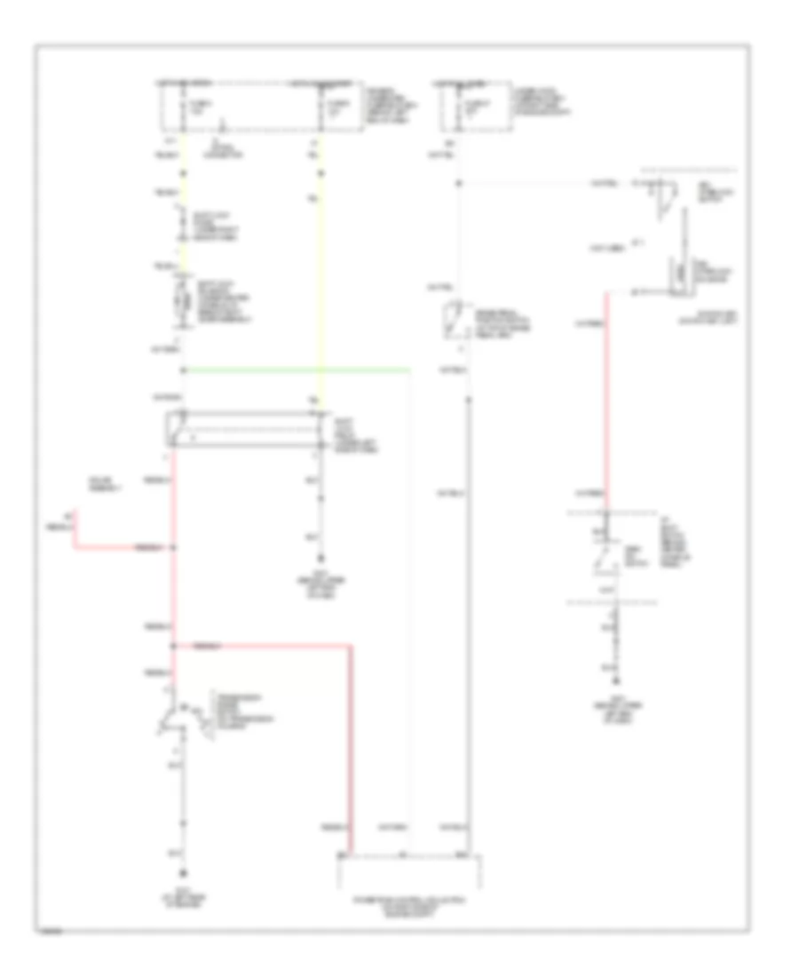
SHIFT INTERLOCK
Shift Interlock Wiring Diagram for Acura MDX Touring 2004
List of elements for Shift Interlock Wiring Diagram for Acura MDX Touring 2004:
- (not used)
- A/t shift switch (behind center console panel)
- B21
- B39
- Brake pedal position switch (at top of brake pedal arm)
- Driver's underdash fuse/relay box (behind left end of dash)
- Fuse 47 20a
- Fuse 8 7.5a
- Fuse 9 10a
- G101 (at left rear of engine)
- G401 (behind upper left end of dash)
- Gauge assembly
- Hot at all times
- Hot in acc or on
- Hot in on or start
- Ignition key switch/ key light
- Key interlock solenoid
- Key interlock switch
- M11
- Option connector
- Park pin switch
- Powertrain control mdule (pcm) (on right side of engine compt)
- Shift lock diode (under right side of dash)
- Shift lock relay (under left side of dash)
- Shift lock solenoid (under center console, at base of shift lever assembly)
- Transmission range switch (on transmission housing)
- Under-hood fuse/relay box (at right side of engine compt)
 Dansk
Dansk Deutsch
 Ελληνικά
 English
 English
 Español
 Suomi
Suomi Français
 Français
 עברית
עברית Hrvatski
 Magyar
 Italiano
 日本語
日本語 한국어
한국어 Nederlands
 Polski
 Português
 Português
 Română
 Русский
 Slovenčina
 Slovenščina
 Svenska
 Türkçe
 中文 (中国)
 Čeština