SHIFT INTERLOCK
Reverse Lockout Wiring Diagram, M/T for Acura TL 2007
 https://portal-diagnostov.com/license.html
Automotive Electricians Portal FZCO
Automotive Electricians Portal FZCO
https://portal-diagnostov.com/license.html
https://portal-diagnostov.com/license.html
Automotive Electricians Portal FZCO
Automotive Electricians Portal FZCO
List of elements for Reverse Lockout Wiring Diagram, M/T for Acura TL 2007:
- A10
- E22
- Ecm (behind center of dash)
- Fuse 15a
- Hot in on or start
- Junction connector c105 (left side of engine)
- Junction connector c507 (left side of dash)
- N29
- Reverse lockout solenoid (on transmission)
- Rvs
- Under-dash fuse/relay box (behind left end of dash)
- Vbsol
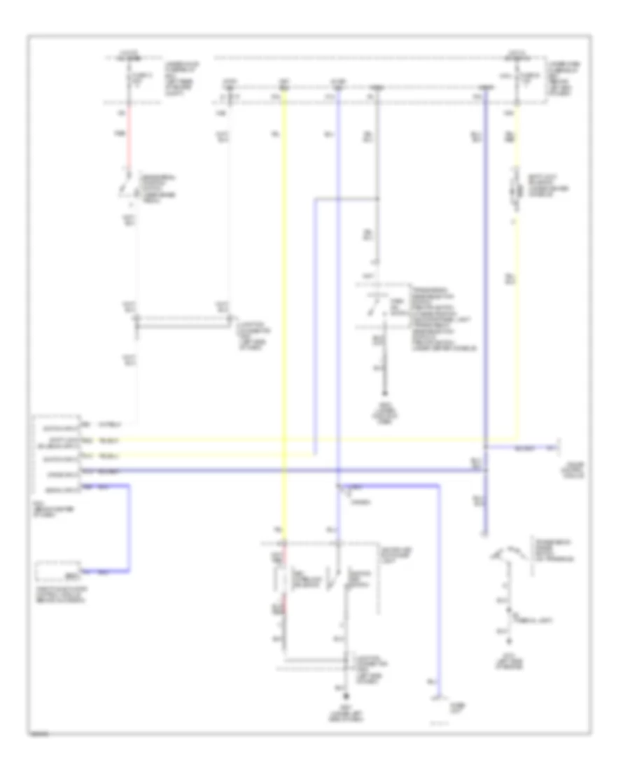
Shift Interlock Wiring Diagram, A/T for Acura TL 2007
List of elements for Shift Interlock Wiring Diagram, A/T for Acura TL 2007:
- A11
- A26
- Atp-p
- Brake pedal position switch (near brake pedal)
- Canada
- D13
- D14
- Drive input
- Fuse 13 20a
- Fuse 32 7.5a
- G101 (left side of engine)
- G501 (under left side of dash)
- G503 (under middle of dash)
- Gauge control module
- Hot at all times
- Hot in acc or on
- Ig key sw
- Ignition key switch
- Ignition key switch/key light
- Imoes unit
- Junction connector c507 (left side of dash)
- Junction connector c508 (left side of dash)
- Key interlock solenoid
- Key sol
- Micu
- N26
- N39
- P-pin
- P13
- P15
- P16
- Park pin switch
- Pcm (behind center of dash)
- Red
- S2 (thermal joint)
- Sedf
- Shift lock e22
- Shift lock solenoid (under center console)
- Signal input
- Solenoid input
- Stop sw
- Switch input
- Throttle actuator control module (behind glove box)
- Transmission gear selection switch/ park pin switch a/t gear position indicator panel light (transmission gear selection switch & park pin switch: under center console)
- Transmission range switch (on transaxle)
- Under-dash fuse/relay box (behind left end of dash)
- Under-hood fuse/relay box (left rear of engine compt)

 Dansk
Dansk Deutsch
 Ελληνικά
 English
 English
 Español
 Suomi
Suomi Français
 Français
 עברית
עברית Hrvatski
 Magyar
 Italiano
 日本語
日本語 한국어
한국어 Nederlands
 Polski
 Português
 Português
 Română
 Русский
 Slovenčina
 Slovenščina
 Svenska
 Türkçe
 中文 (中国)