
 Dansk
Dansk Deutsch
 Ελληνικά
 English
 English
 Español
 Suomi
Suomi Français
 Français
 עברית
עברית Hrvatski
 Magyar
 Italiano
 日本語
日本語 한국어
한국어 Nederlands
 Polski
 Português
 Português
 Română
 Русский
 Slovenčina
 Slovenščina
 Svenska
 Türkçe
 中文 (中国)

SHIFT INTERLOCK
Shift Interlock Wiring Diagram for Volvo S80 2007
List of elements for Shift Interlock Wiring Diagram for Volvo S80 2007:
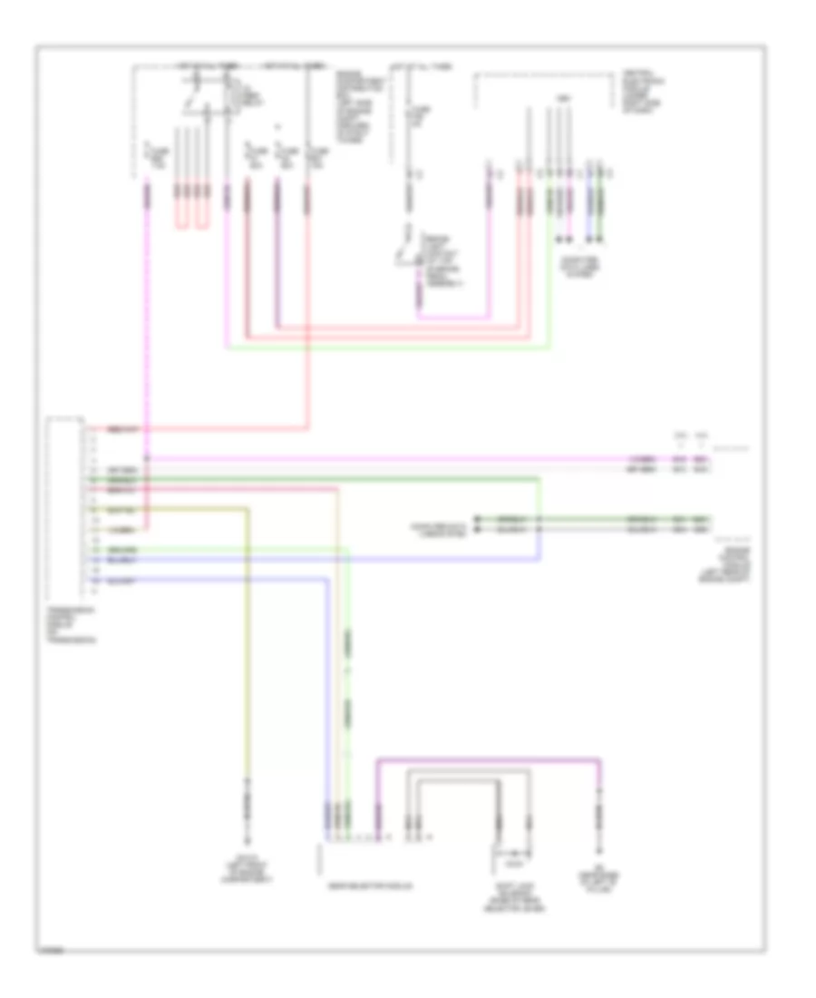

ANTI-LOCK BRAKESCOMPUTER DATA LINESANTI-THEFTAIR CONDITIONINGCOOLING FANBODY CONTROL MODULESCRUISE CONTROLDEFOGGERSELECTRONIC POWER STEERINGENGINE PERFORMANCEEXTERIOR LIGHTSGROUND DISTRIBUTIONHORNELECTRONIC SUSPENSIONHEADLIGHTSINSTRUMENT CLUSTERPOWER DOOR LOCKSNAVIGATIONINTERIOR LIGHTSPOWER TOP/SUNROOFMEMORY SYSTEMSRADIOPOWER WINDOWSPOWER DISTRIBUTIONSTARTING/CHARGINGPOWER SEATSPOWER MIRRORSSHIFT INTERLOCKSUPPLEMENTAL RESTRAINTSTRANSMISSIONTRUNK, TAILGATE, FUEL DOORWARNING SYSTEMSWIPER/WASHER