AIR CONDITIONING
A/C Wiring Diagram for Toyota Pickup SR5 1994
 https://portal-diagnostov.com/license.html
Automotive Electricians Portal FZCO
Automotive Electricians Portal FZCO
https://portal-diagnostov.com/license.html
https://portal-diagnostov.com/license.html
Automotive Electricians Portal FZCO
Automotive Electricians Portal FZCO
List of elements for A/C Wiring Diagram for Toyota Pickup SR5 1994:
- 1994 vftc c
- 3.0l a/t w/ 4wd only
- 3.0l only
- 3.0l w/ 4wd only
- A/c amplifier (right side of i/p)
- A/c cut relay (right side of i/p)
- A/c dual pressure switch (right side of i/p)
- A/c fuse 10a
- A/c idle-up valve (right rear of engine compt)
- A/c magnetic clutch (right front of engine compt)
- A/c switch
- A/c thermistor (right side of i/p)
- A24
- All others
- Alt fuse 80a
- B10
- B19
- Blower motor (right side of i/p)
- Blower resistor (right side of i/p)
- Blower switch
- Engine control module (right side of i/p)
- Engine control systems (efi main relay)
- Except 2.4l
- G200 (left kick panel)
- Gauge fuse 10a
- Heater fuse 30a
- Heater relay
- Hot at all times
- Hot in run or start
- Igniter (left side of engine compt)
- Integration relay
- Interior lights system (rheostat)
- Interior lights system (tail fuse)
- J/b 1 (left kick panel)
- Off
- R/b 2 (right side of engine compt)
- R/b 3 (right side of glove box)
- Red
- Water temperature switch (center rear of engine compt)
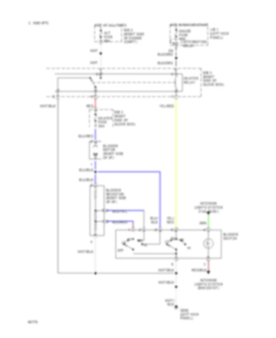
Heater Wiring Diagram for Toyota Pickup SR5 1994
List of elements for Heater Wiring Diagram for Toyota Pickup SR5 1994:
- Alt fuse 80a
- Blower motor (right side of i/p)
- Blower resistor (right side of i/p)
- Blower switch
- C 1995 vftc
- G200 (left kick panel)
- Gauge fuse 10a
- Heater fuse 30a
- Heater relay
- Hot at all times
- Hot in run or start
- Integration relay
- Interior lights system (rheostat)
- Interior lights system (tail fuse)
- J/b 1 (left kick panel)
- Off
- R/b 2 (right side of engine compt)
- R/b 3 (right side of glove box)
- Red

 Dansk
Dansk Deutsch
 Ελληνικά
 English
 English
 Español
 Suomi
Suomi Français
 Français
 עברית
עברית Hrvatski
 Magyar
 Italiano
 日本語
日本語 한국어
한국어 Nederlands
 Polski
 Português
 Português
 Română
 Русский
 Slovenčina
 Slovenščina
 Svenska
 Türkçe
 中文 (中国)