ANTI-LOCK BRAKES
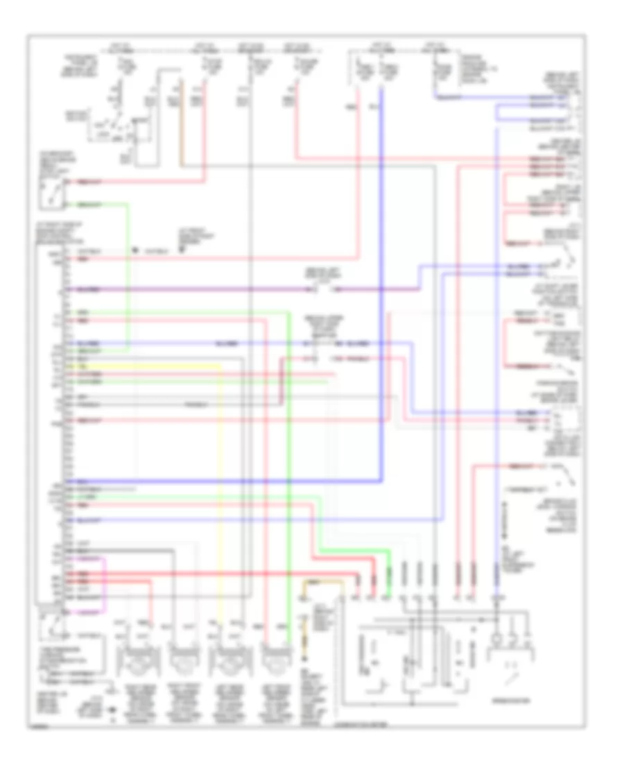
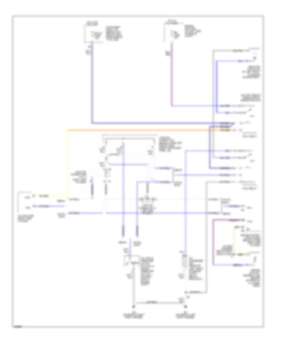
Anti-lock Brakes Wiring Diagram, with Traction Control (1 of 3) for Toyota Avalon XLS 2004
List of elements for Anti-lock Brakes Wiring Diagram, with Traction Control (1 of 3) for Toyota Avalon XLS 2004:
- (at front side of right fender) ea
- (at right side of engine compt) skid control ecu w/ actuator
- (behind left side of dash) j/c 6
- (behind left side of dash) instrument panel j/b
- (behind upper right side of dash) right j/b
- (on bracket, above brake pedal) stop light switch
- +bm
- +bs
- A/t shift lever position switch (on left side of transaxle)
- Abs 1 fuse 30a
- Abs 2 fuse 40a
- Abs ind
- Acc
- Am2 fuse 15a
- B14
- B16
- B20
- B21
- B22
- Brake fluid level warning switch (on brake fluid reservoir)
- Brake ind
- Brk
- Brl
- C13
- C14
- C19
- C20
- Center j/b (behind center of dash)
- Center j/b (behind center of dash)
- Combination meter
- D/g
- Data link connector 3 (below left side of dash)
- Daytime running light relay (behind left side of dash)
- Dome fuse 15a
- Eb (except xrs: at rear left side of cylinder head) (xrs: left rear of engine)
- Ecu-ig fuse 10a
- Ed (at left front suspension tower)
- Engine room r/b (integral to engine room j/b)
- Fl+
- Fl-
- Fr+
- Fr-
- Gauge fuse 10a
- Gnd1
- Gnd2
- Hot at all times
- Hot in on or start
- Ig1
- Ignition switch
- Ind tire pressure
- Init
- Instrument panel j/b (behind left side of dash)
- J/c 3 (behind right side of dash)
- J/c 4 (behind right side of dash)
- J/c 6 (behind left side of dash)
- Left front abs speed sensor (on inside of left front wheel assembly)
- Left rear abs speed sensor (on inside of right rear wheel assembly)
- Lock
- Off
- Parking brake switch (at base of park brake lever)
- Pkb
- Red
- Right front abs speed sensor (on inside of right front wheel assembly)
- Right j/b (behind upper right side of dash)
- Right rear abs speed sensor (on inside of right rear wheel assembly)
- Rl+
- Rl-
- Rr+
- Rr-
- Sil
- Sp1
- Speedometer
- Start
- Stop fuse 15a
- Stp
- Tire pressure warning standardization switch
- Tsi
- Wtir
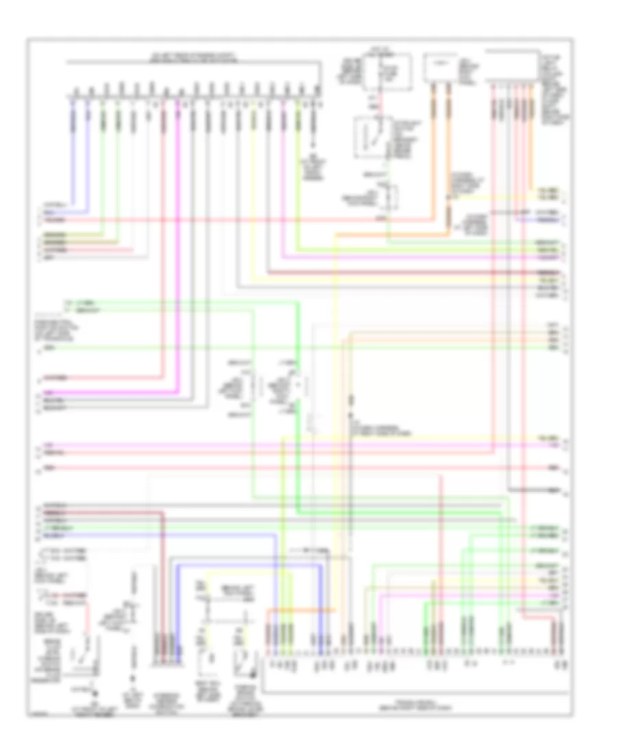
Anti-lock Brakes Wiring Diagram, with Traction Control (2 of 3) for Toyota Avalon XLS 2004
List of elements for Anti-lock Brakes Wiring Diagram, with Traction Control (2 of 3) for Toyota Avalon XLS 2004:
- (behind left kick panel) j/b 3
- (behind left side of dash)
- (in dash harness, at left side of dash)
- (in dash harness, at right side of dash) i15
- (on left rear of engine compt) abs & ba & trac & vsc actuator
- A14
- A15
- A18
- Active light relay (column shift: behind left side of dash) (floor shift: behind right side of dash)
- B15
- B18
- Body ecu
- Brake fluid level warning switch (on brake fluid reservoir)
- Brl
- Ccs
- D11
- D16
- Driver side j/b (behind left side of dash)
- Ed (at front of left front fender)
- Ee (at front of left front fender)
- Eng+
- Eng-
- F16
- Gnd
- Hot at all times
- I12
- I15 (in dash harness, at right side of dash)
- Ig (at left end of dash)
- Ig1
- J/b 3 (behind left kick panel)
- J/b 4 (behind right kick panel)
- Lbl
- Lvl2
- Ml+
- Ml-
- Nca
- Neo
- Park/neutral position switch (on left side of transaxle)
- Parking brake switch (on parking brake lever bracket)
- Pkb
- Pkb2
- Red
- Rss
- Sflh
- Sflr
- Sfrh
- Sfrr
- Smc1
- Smc2
- Src1
- Src2
- Srlh
- Srlr
- Srrh
- Srrr
- Ss1
- Ss2
- Steering sensor (combination switch)
- Stop fuse 15a
- Stoplight switch (on bracket, above brake pedal)
- Translate ecu (behind right side of dash)
- Trc+
- Trc-
- Vsc+
- Vsc-
Anti-lock Brakes Wiring Diagram, with Traction Control (3 of 3) for Toyota Avalon XLS 2004
List of elements for Anti-lock Brakes Wiring Diagram, with Traction Control (3 of 3) for Toyota Avalon XLS 2004:
- (behind center of dash) center j/b
- (behind left side of dash) daytime running light relay
- (in instrument panel wire, behind right side of dash) i7
- +b1
- A11
- A19
- Cty
- Dcty
- Detection
- Dmlp
- Dswd
- Dswl
- Ecu-b fuse 10a
- Ecu-ig fuse 10a
- Ehw
- Glass breakage sensor ecu (behind upper right side of dash)
- Gmic
- Gnd
- Head
- Horn
- Horns system
- Hot at all times
- Hot in on or start
- Hzad
- I1 (in instrument panel wire, at left side of dash)
- I11
- I2 (in instrument panel wire, at left side of dash)
- I8 (in instrument panel wire, behind right end of dash)
- Ind
- Instrument panel j/b (behind left side of dash, at lower finish panel)
- Integration relay
- Iout
- Irsg
- Junction connector 10 (at left side of luggage compt)
- Junction connector 6 (behind left side of dash)
- Junction connector 7 (at right kick panel)
- Ksw
- Left front door key lock & unlock switch, door unlock detection switch (at rear of left front door)
- Lock
- Lswd
- Lswp
- Luggage compartment light switch (at center rear of luggage compt)
- Mic
- Micro- phone
- Nca
- Prcty
- Red
- Rheostat
- Right front door key lock & unlock switch, door unlock detection switch (at rear of right front door)
- Right j/b (behind upper right side of dash)
- S+b
- Security ind
- Security indicator
- Srly
- Starting/ charging system
- Trig
- Turn signal flasher relay (behind left side of dash, on instrument panel j/b)
- Tvip ecu (behind right side of dash)
- Tvss
- Ul2
- Ul3
- Unlk
- Unlock warning switch (on steering column, behind ignition key cylinder)
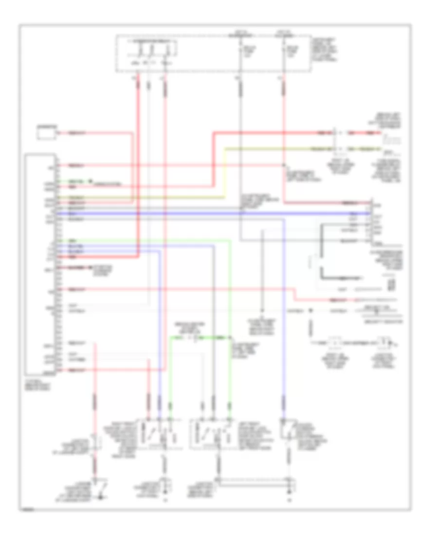
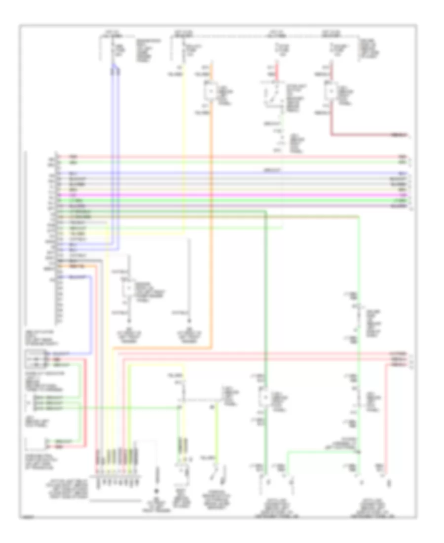
Anti-lock Brakes Wiring Diagram, without Traction Control (1 of 2) for Toyota Avalon XLS 2004
List of elements for Anti-lock Brakes Wiring Diagram, without Traction Control (1 of 2) for Toyota Avalon XLS 2004:
- (in dash harness, at left kick panel) i4
- A12
- A13
- A18
- Abs
- Abs actuator & ecu (on left rear of engine compt)
- Abs fuse 60a
- Active light relay (column shift: behind left side of dash) (floor shift: behind right side of dash)
- B13
- B14
- B18
- Bat
- Body ecu (behind left side of dash)
- Brl
- D10
- D11
- D16
- Data link connector 2 (behind left side of dash, on instrument panel j/b)
- Data link connector 3 (behind left side of dash, on instrument panel j/b)
- Diode (a/t indicator light 1) (behind center of dash, taped to harness)
- Driver side j/b (behind left side of dash)
- Ebdw
- Ecu-ig 2 fuse 10a
- Ed (at front of left front fender)
- Ee (at front of left front fender)
- Engine room j/b (on left front inner fender panel)
- Engine room r/b 5 (on left inner fender panel)
- F10
- F13
- F16
- Fl+
- Fl-
- Fr+
- Fr-
- Gauge 1 fuse 10a
- Gnd
- Gnd1
- Gnd2
- H18
- Hot at all times
- Hot in on or start
- Ig1
- J/b 3 (behind left kick panel)
- J/b 4 (behind right kick panel)
- Park/neutral position switch (on left side of transaxle)
- Parking brake switch (on parking brake lever bracket)
- Pkb
- Pkb2
- Red
- Rl+
- Rl-
- Rr+
- Rr-
- Sp1
- Stop fuse 15a
- Stoplight switch (on bracket, above brake pedal)
- Stp
Anti-lock Brakes Wiring Diagram, without Traction Control (2 of 2) for Toyota Avalon XLS 2004
List of elements for Anti-lock Brakes Wiring Diagram, without Traction Control (2 of 2) for Toyota Avalon XLS 2004:
- (in dash harness, behind right side of dash) i2
- (on left side of engine compt) engine room r/b
- A/c amplifier (right side of dash)
- A/c condenser fan resistor (left front of engine compt, behind headlight)
- A/c triple pressure switch (a/c dual & single pressure switch) (on right side of engine compt)
- Cfn+
- Cfn-
- Ea (on rear of right front fender)
- Ec (on rear of left front fender)
- Ecu-ig fuse 7.5a
- Engine control module (ecm) (behind lower right side of dash)
- Engine coolant temperature sensor (on rear of cylinder head)
- Engine room r/b (on left side of engine compt)
- Fan
- Fan 1 relay
- Fan 2 relay
- Hatch back
- Hot at all times
- Hot in on or start
- Instrument panel j/b (behind left side of dash, near base of ``a" pillar)
- J13
- J14
- Junction connector 1 (behind upper left side of dash, above instrument panel j/b)
- Junction connector 12 (left side of dash)
- Junction connectors 13 & 14 (right side of dash)
- Radiator fan motor (at left front of engine compartment)
- Rdi fuse 30a
- Sedan
- Single
- Thw

 Dansk
Dansk Deutsch
 Ελληνικά
 English
 English
 Español
 Suomi
Suomi Français
 Français
 עברית
עברית Hrvatski
 Magyar
 Italiano
 日本語
日本語 한국어
한국어 Nederlands
 Polski
 Português
 Português
 Română
 Русский
 Slovenčina
 Slovenščina
 Svenska
 Türkçe
 中文 (中国)