INSTRUMENT CLUSTER
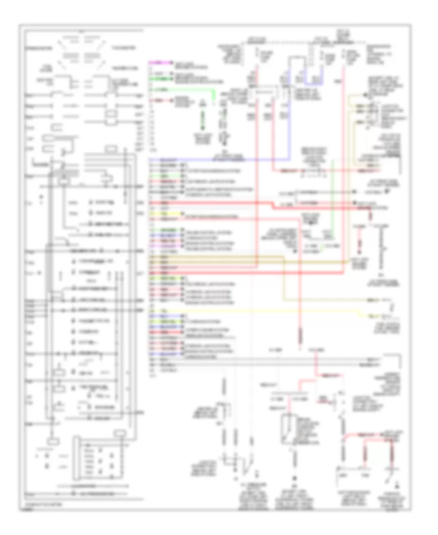
Instrument Cluster Wiring Diagram, with Navigation (1 of 2) for Toyota Avalon XLS 2004

List of elements for Instrument Cluster Wiring Diagram, with Navigation (1 of 2) for Toyota Avalon XLS 2004:
- (behind right side of dash) translate ecu
- (or red)
- A10
- A11
- A12
- A12 a13
- A13
- A14
- A15
- A16
- A17
- A18
- A19
- A20
- A21
- A22
- Abs ind
- Air conditioning system
- Anti-lock brakes system
- Automatic a/c
- B10
- B11
- B12
- B13
- B14
- B15
- B16
- B17
- B18
- Back light circuit
- Brake ind
- Brl
- C10
- C11
- C12
- C13
- C14
- C15
- C16
- C17
- C18
- C19
- C20
- Charge ind
- Control
- Cpu
- Cruise ind
- D10
- Display
- Dome fuse 7.5a
- Door ind
- Drive sig
- Driver seat belt ind
- Driver side j/b (behind left side of dash)
- E10
- E11
- E12
- E13
- Eb (at left front of engine, on surge tank)
- Ecu-acc fuse 5a
- Ecu-ig fuse 10a
- Engine controls system
- F11
- F12
- F13
- F15
- F16
- F17
- F18
- F19
- F20
- F24
- Field magnetic sensor (in front center of roof)
- Fuel pump & sender (in fuel tank)
- Gauge fuse 10a
- Gnd
- Hot at all times
- Hot in acc or on
- Hot in on or start
- Hot w/ tail relay energized
- Interior lights system
- J/b 3 (behind left kick panel)
- J/b 4 (behind right kick panel)
- J/c 2 (behind center of dash)
- Junction connector 9 (on top of right kick panel)
- L11
- Light
- Lvl2
- Malfunction ind lamp
- Multi display
- Navigation display
- Nca
- Oil ind
- Oil pressure switch (on lower left front of engine)
- Panel fuse 5a
- Passenger seat belt ind
- Pnk
- Power
- Radio fuse 15a
- Rear lights ind
- Red
- Relay
- Slip ind
- Srs ind
- Starting/charging system
- Trac off ind
- Vmid
- Vsc ind
- W/ traction
- W/o traction
- Warning system
- Washer ind
- Water temperature sender (on top front of engine)
- Wiper/washer system
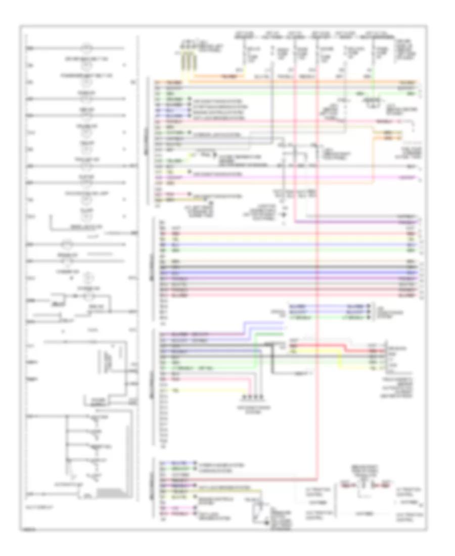
Instrument Cluster Wiring Diagram, with Navigation (2 of 2) for Toyota Avalon XLS 2004
List of elements for Instrument Cluster Wiring Diagram, with Navigation (2 of 2) for Toyota Avalon XLS 2004:
- (at front side of right fender)
- (behind right side of dash) junction connector 3 & 4
- (except xrs:
- (except xrs: at rear left side of cylinder head) (xrs: at rear of engine) ec
- (in instrument panel harness, behind upper left side of dash)
- (on top of transaxle)
- (w/o abs) vehicle speed sensor (combination meter)
- (xrs: on left front suspension tower)
- A10
- A11
- A12
- A14
- A15
- A16
- A17
- A18
- A19
- A20
- A21
- A22
- A23
- A24
- A25
- A26
- A27
- A29
- A30
- A31
- A32
- A33
- A34
- A35
- A36
- A37
- A38
- A39
- A40
- Abs ind
- Ambient temperature sensor (at middle front of engine compt)
- Anti-lock brakes systeam
- Anti-lock brakes systeam engine controls system
- Anti-lock brakes system
- At left front suspension tower)
- B16
- B18
- B20
- B21
- B22
- Brake fluid level warning switch (on brake fluid reservoir)
- Brake ind
- Brk
- Buzzer
- C11
- C18
- C19
- C20
- Center j/b (behind left side of dash)
- Charge ind
- Combination meter
- Cruise control system
- Cruise ind
- Daytime running light relay (behind left side of dash)
- Dome fuse 15a
- Door ind
- Engine controls system
- Engine room r/b (integral to engine room j/b)
- Exterior lights system
- Fuel gauge
- Fuel ind
- Fuel pump & fuel sender (in fuel tank)
- Gauge fuse 10a
- Head ind
- Head rh upr fuse 10a
- Headlights system
- High beam ind
- Hot at all times
- Hot in on or start
- Hot w/ dimmer relay energized
- Illumination
- Ind
- Instrument panel j/b (behind left side of dash)
- Interior lights system
- Junction connector 1 (at left side of engine compt)
- Junction connector 2 (behind left side of dash)
- Junction connector 5 & 6 (behind right side of dash)
- Left turn ind
- Maint reqd ind
- Malfunction ind
- O/d off ind
- Odo/trip lcd
- Oil pressure ind
- Oil pressure switch (except xrs: on lower left side of engine) (xrs: at right rear of engine)
- Out side temperature lcd
- Parking brake switch (at base of park brake lever)
- Pkb
- Red
- Right j/b (behind upper right side of dash)
- Right turn ind
- Seat belt ind
- Slip ind
- Speedometer
- Srs ind
- Starting/charging system
- Tachometer
- Temperature
- Tire pressure
- Vsc
- W/ abs
- W/o abs
- Warning system
- Washer level ind
- Wiper/washer system
Instrument Cluster Wiring Diagram, without Navigation (1 of 2) for Toyota Avalon XLS 2004
List of elements for Instrument Cluster Wiring Diagram, without Navigation (1 of 2) for Toyota Avalon XLS 2004:
- (behind right side of dash) translate ecu
- (or red)
- A10
- A11
- A12
- A12 a13
- A13
- A14
- A15
- A16
- A17
- A18
- A19
- A20
- A21
- A22
- Abs ind
- Air conditioning system
- Anti-lock brakes system
- Automatic a/c
- B10
- B11
- B12
- B13
- B14
- B15
- B16
- B17
- B18
- Back light circuit
- Brake ind
- Brl
- C10
- C11
- C12
- C13
- C14
- C15
- C16
- C17
- C18
- C19
- C20
- Charge ind
- Control
- Cpu
- Cruise ind
- D10
- Display
- Dome fuse 7.5a
- Door ind
- Drive sig
- Driver seat belt ind
- Driver side j/b (behind left side of dash)
- E10
- E11
- E12
- E13
- E14
- E15
- Eb (at left front of engine, on surge tank)
- Ecu-acc fuse 5a
- Ecu-ig fuse 10a
- Engine controls system
- F11
- F13
- F15
- Field magnetic sensor (automatic a/c) (in front center of roof)
- Fuel pump & sender (in fuel tank)
- G20
- Gauge fuse 10a
- Gnd
- Hot at all times
- Hot in acc or on
- Hot in on or start
- Hot w/ tail relay energized
- Interior lights system
- J/b 3 (behind left kick panel)
- J/b 4 (behind right kick panel)
- J/c 2 (behind center of dash)
- Junction connector 9 (on top of right kick panel)
- L11
- Light
- Lvl2
- Malfunction ind lamp
- Mode
- Multi display
- Nca
- Odo/trip
- Oil ind
- Oil pressure switch (on lower left front of engine)
- Panel fuse 5a
- Passenger seat belt ind
- Pnk
- Power
- Radio fuse 15a
- Rear lights ind
- Red
- Relay
- Reset/adj
- Slip ind
- Srs ind
- Starting/charging system
- Trac off ind
- Vmid
- Vsc ind
- W/ traction
- W/o traction
- Warning system
- Washer ind
- Water temperature sender (on top front of engine)
- Wiper/washer system
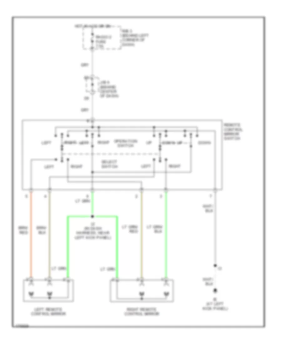
Instrument Cluster Wiring Diagram, without Navigation (2 of 2) for Toyota Avalon XLS 2004
List of elements for Instrument Cluster Wiring Diagram, without Navigation (2 of 2) for Toyota Avalon XLS 2004:
- Down
- Hot in acc or on
- I2 (in dash harness, near left kick panel)
- Ie (at left kick panel)
- J/b 6 (behind center of dash)
- Left
- Left remote control mirror
- Operation switch
- R/b 3 (behind left corner of dash)
- Radio 2 fuse 7.5a
- Remote control mirror switch
- Right
- Right remote control mirror
- Select switch