SHIFT INTERLOCK
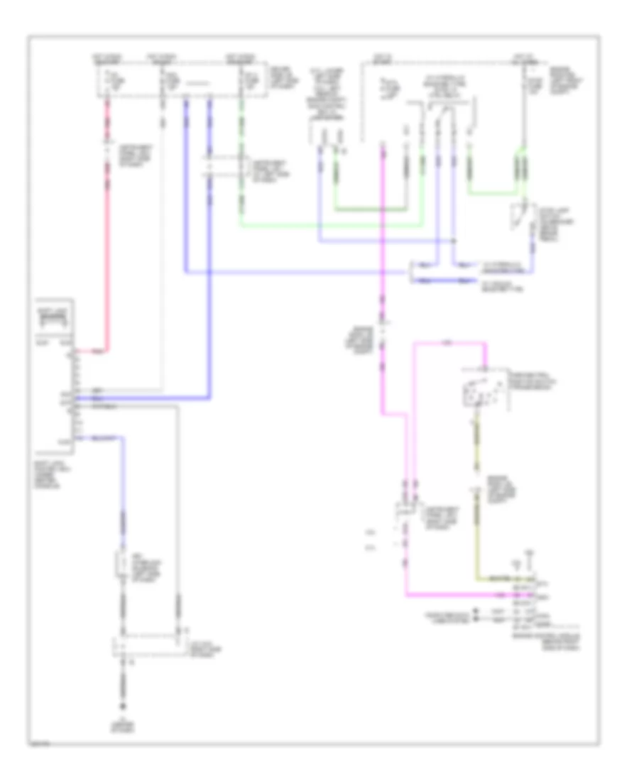
Shift Interlock Wiring Diagram for Toyota Tacoma X-Runner 2009
List of elements for Shift Interlock Wiring Diagram for Toyota Tacoma X-Runner 2009:
- (2.7l: lower left side of dash) (4.0l: left rear of engine compt) skid control ecu w/ actuator
- (w/ hydraulic booster type) stop lp ctrl relay
- 2.7l
- 4.0l
- A11
- Acc
- Acc fuse 7.5a
- B13
- B18
- C12
- C13
- C14
- Canh
- Canl
- Computer data lines system
- Driver side j/b (left side of dash)
- E10
- E14
- Engine control module (behind right side of dash)
- Engine room j/b (left side of engine compt)
- Engine room r/b (left front of engine compt)
- Hot at all times
- Hot in run or acc
- Hot in run or start
- Hot in start
- Ic (center of dash)
- Ig1 2 fuse 10a
- Ig1 fuse 10a
- Instrument panel j/b 1 (at left side of dash)
- Instrument panel j/b 2 (right side of dash)
- J/c 4 & 5 (right side of dash)
- J10
- Key interlock solenoid (left side of dash)
- Kls+
- Nsw
- Park/neutral position switch (transmission)
- Pnk
- Shift lock control ecu (under center console)
- Shift lock solenoid
- Sls+
- Sls-
- Sta
- Sta fuse 7.5a
- Stop fuse 10a
- Stop lamp switch (on bracket, above brake pedal)
- Stp
- Stp2
- Stpo
- W/ hydraulic booster type
- W/ vacuum booster type
 Dansk
Dansk Deutsch
 Ελληνικά
 English
 English
 Español
 Suomi
Suomi Français
 Français
 עברית
עברית Hrvatski
 Magyar
 Italiano
 日本語
日本語 한국어
한국어 Nederlands
 Polski
 Português
 Português
 Română
 Русский
 Slovenčina
 Slovenščina
 Svenska
 Türkçe
 中文 (中国)
 Čeština