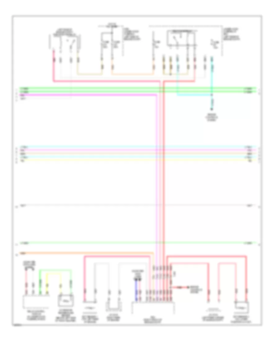
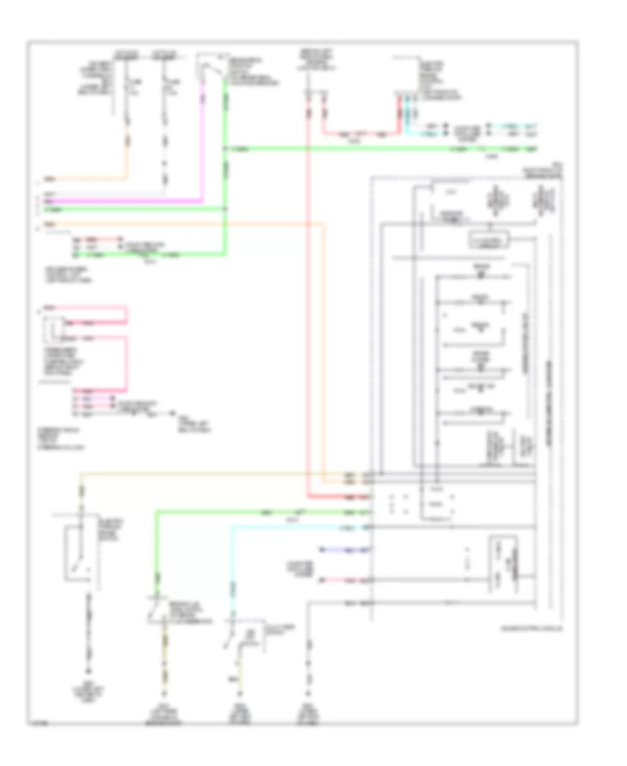
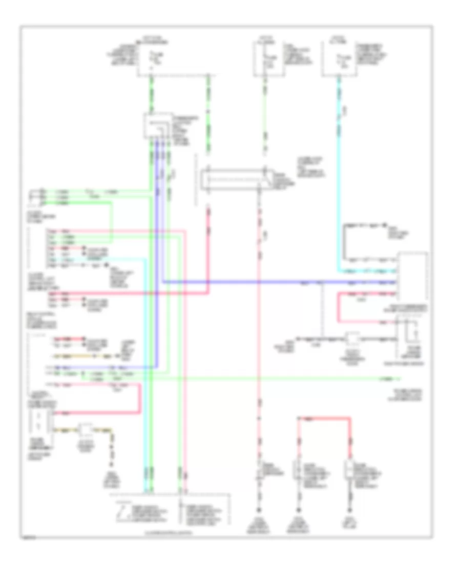
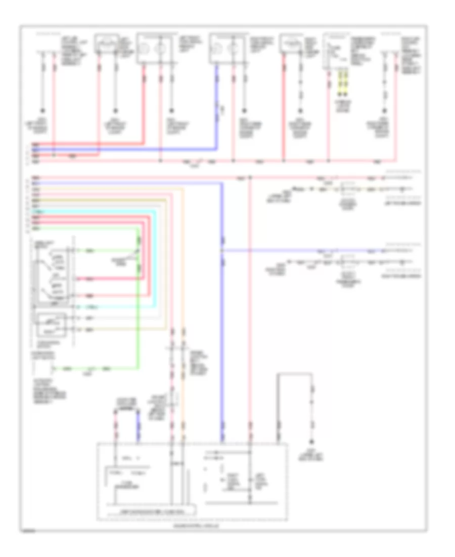
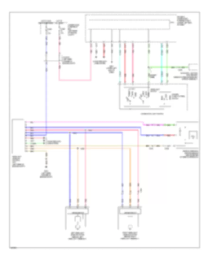
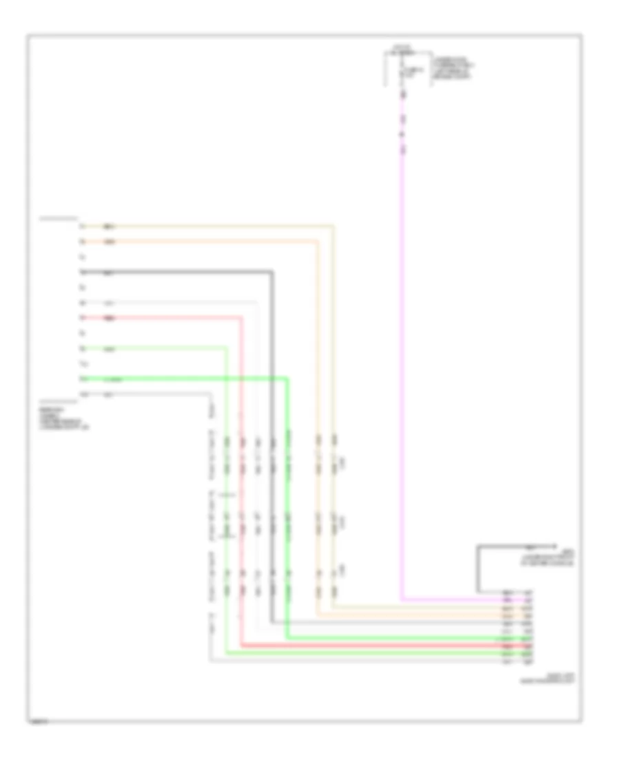
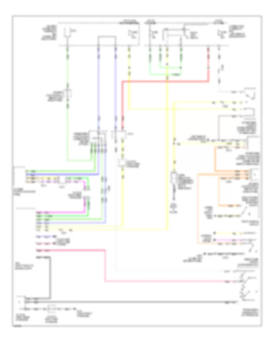
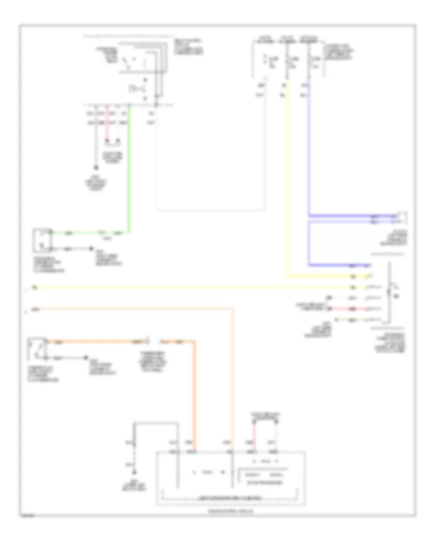
AIR CONDITIONING
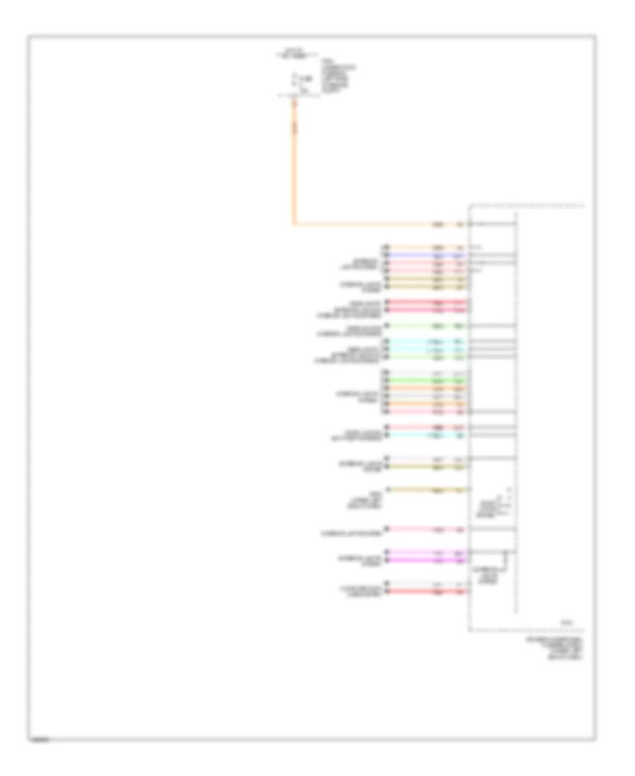
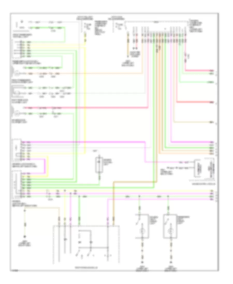
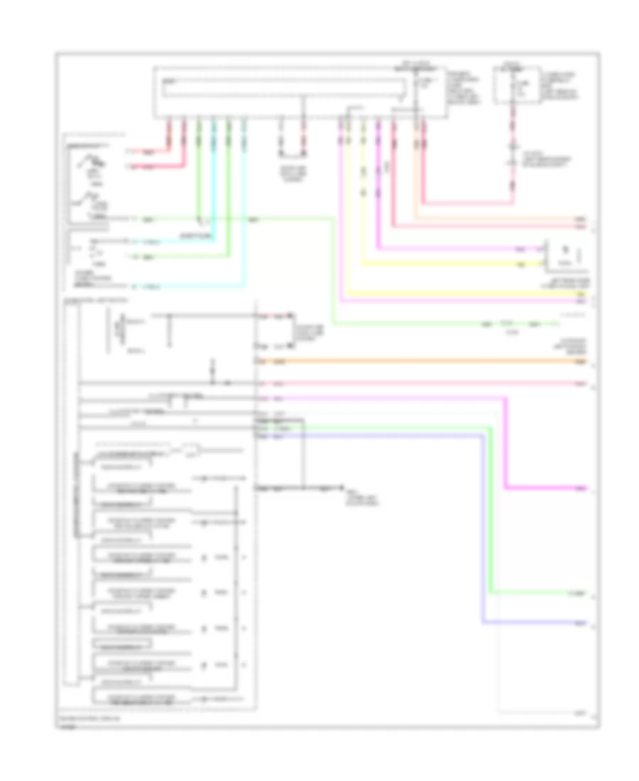
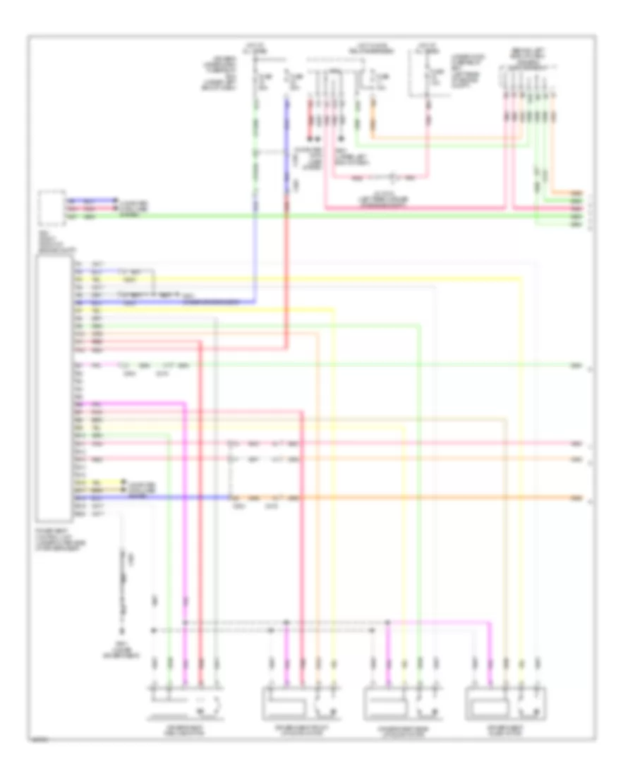
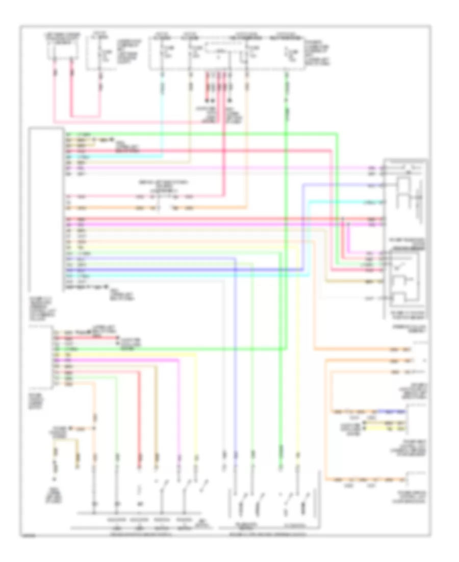
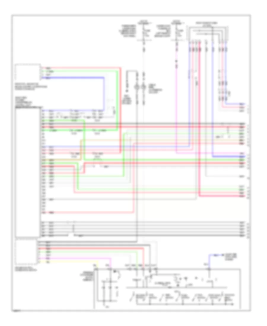
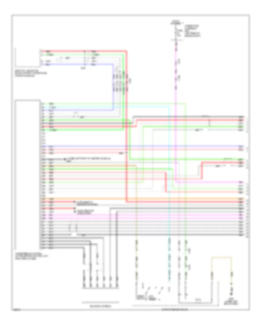
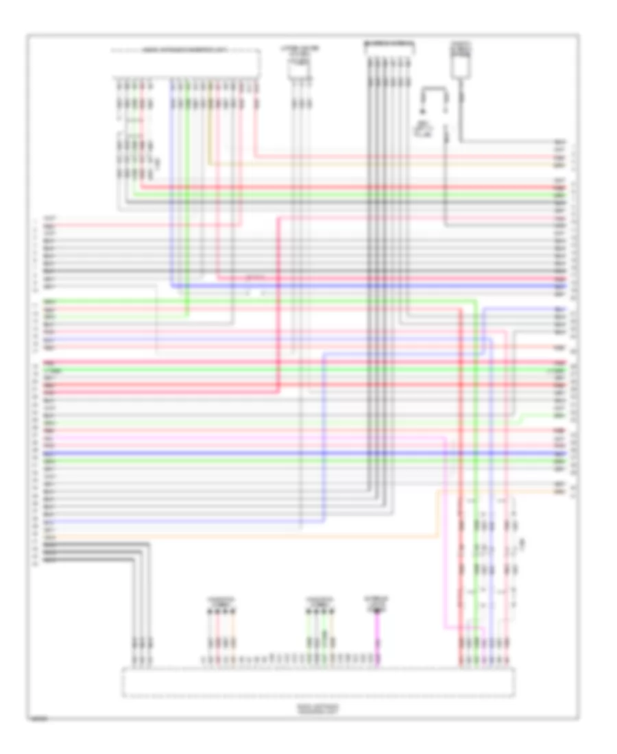
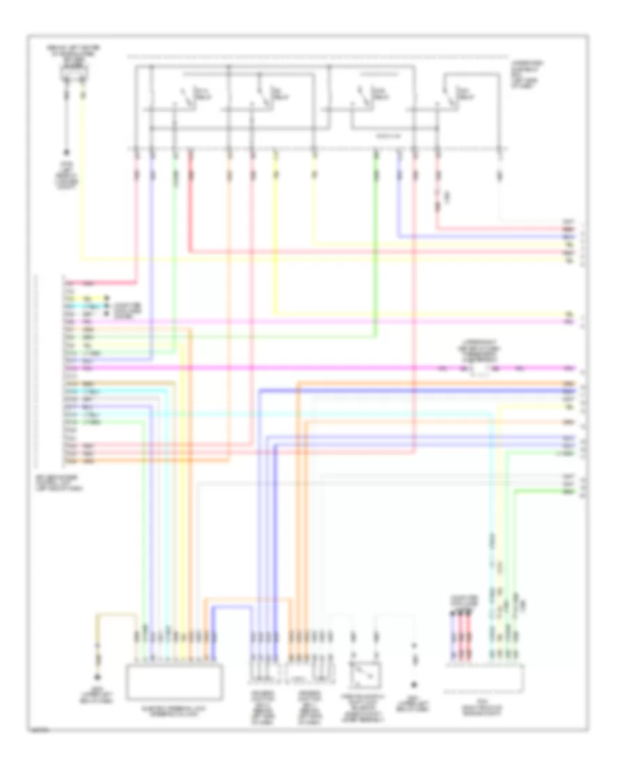
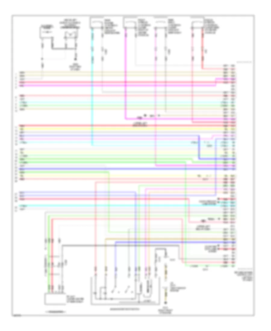
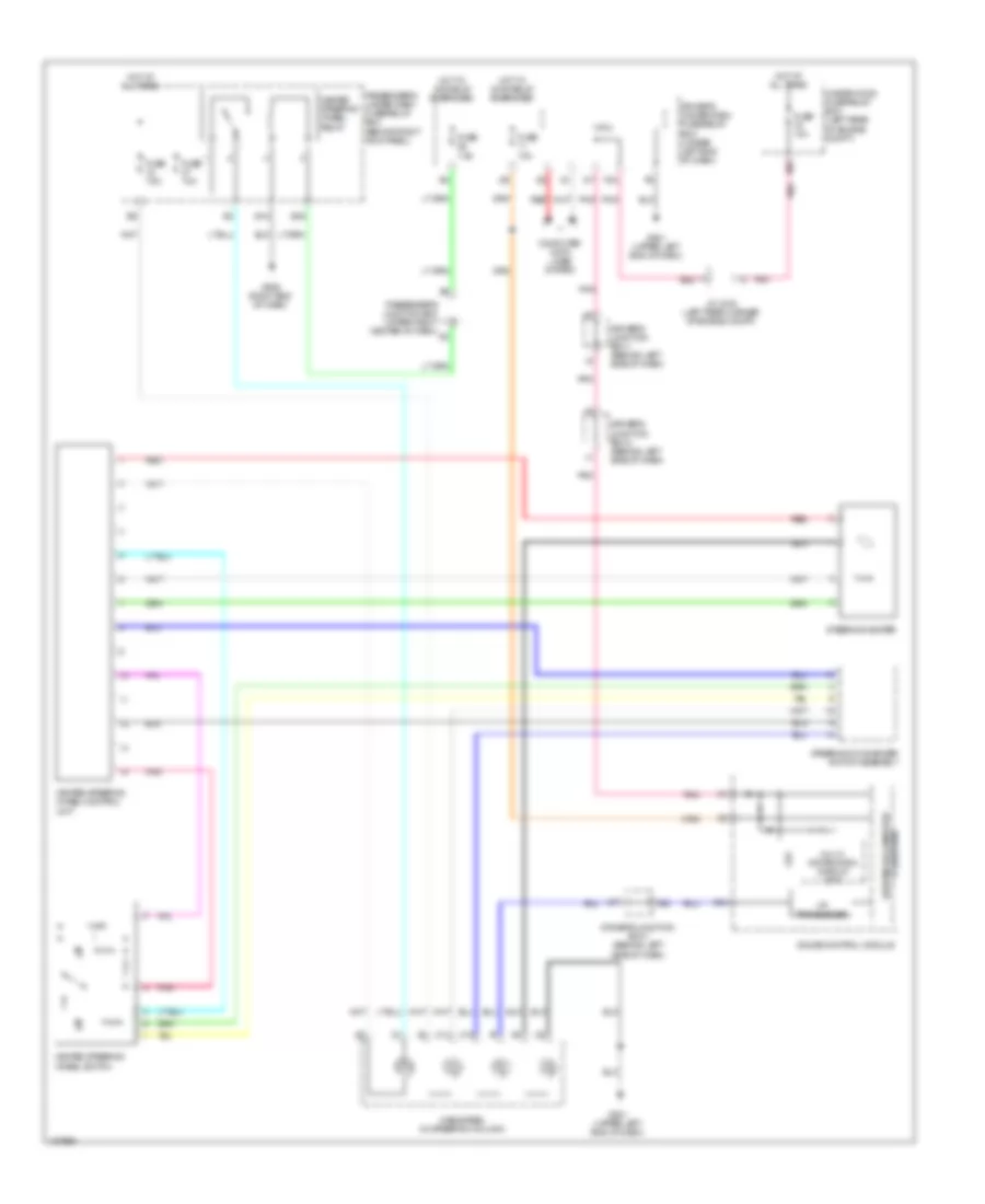
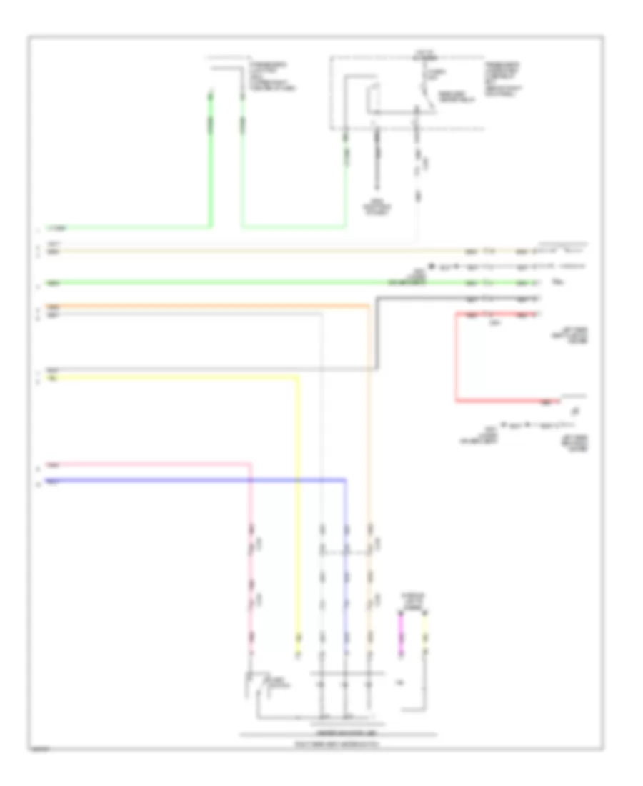
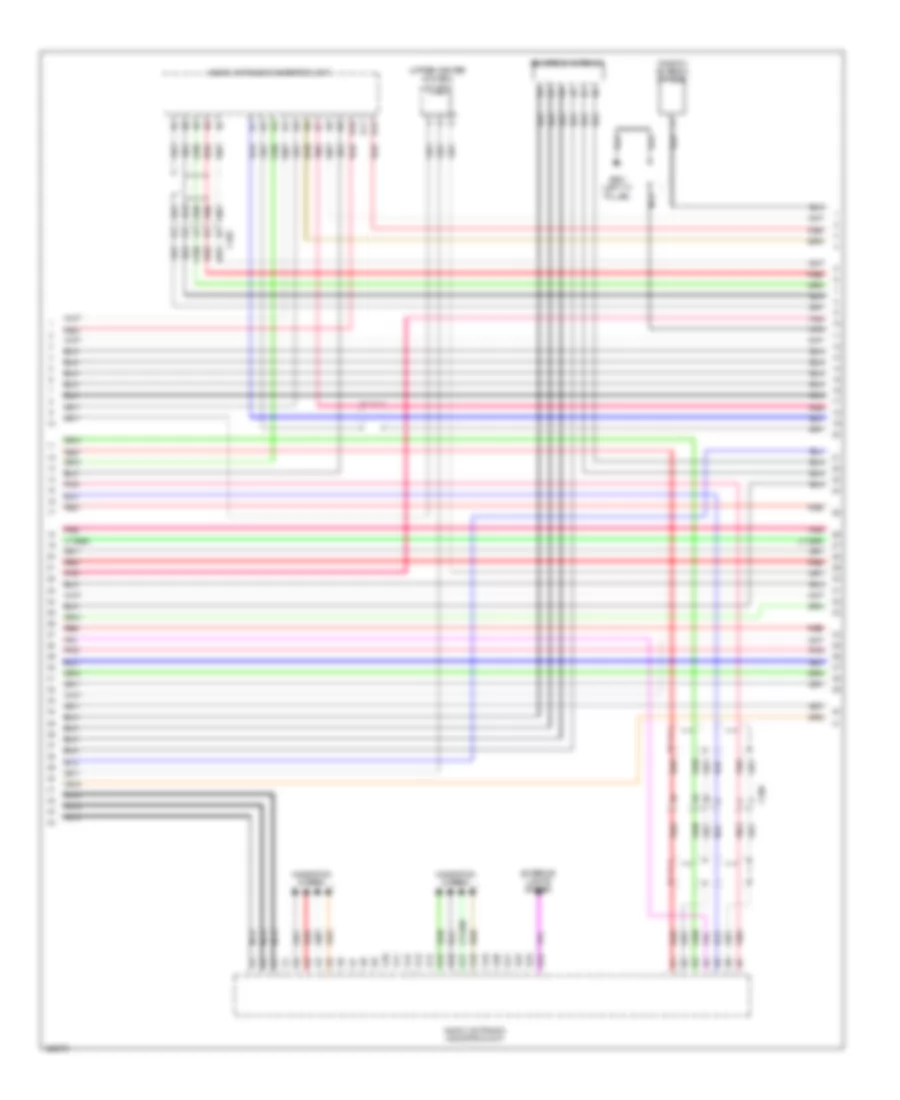
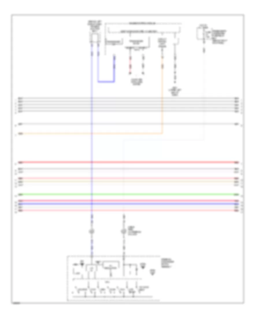
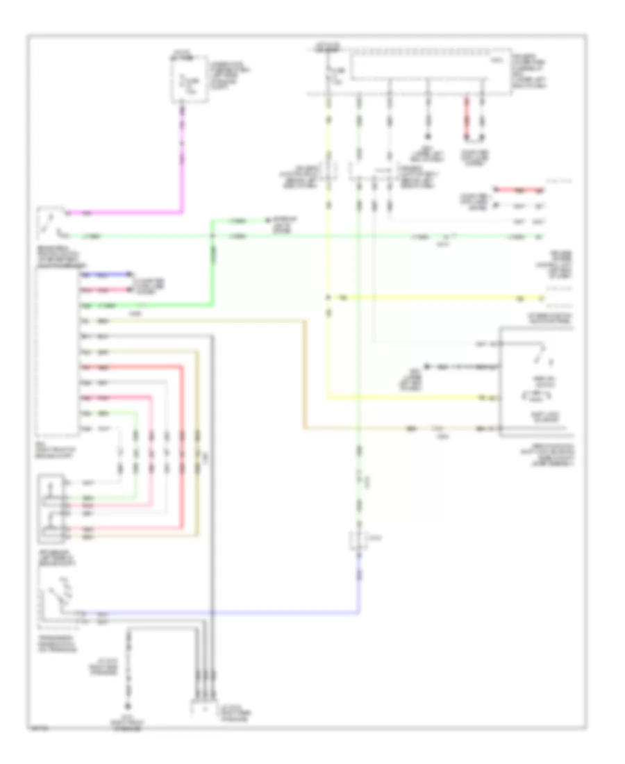
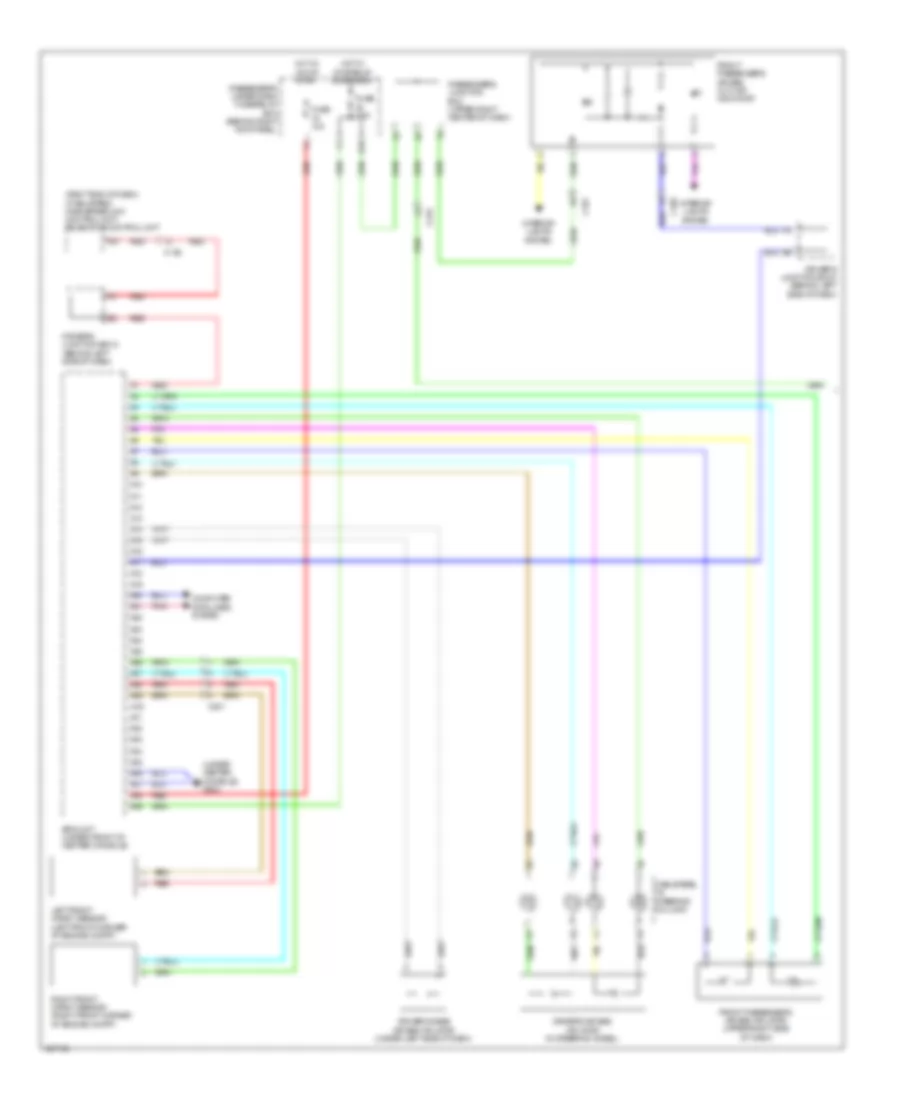
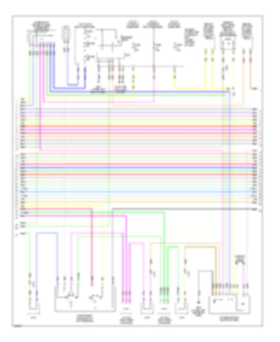
Automatic A/C Wiring Diagram (1 of 4) for Acura RLX 2014
 https://portal-diagnostov.com/license.html
Automotive Electricians Portal FZCO
Automotive Electricians Portal FZCO
https://portal-diagnostov.com/license.html
https://portal-diagnostov.com/license.html
Automotive Electricians Portal FZCO
Automotive Electricians Portal FZCO
List of elements for Automatic A/C Wiring Diagram (1 of 4) for Acura RLX 2014:
- (behind left side of radiator) radiator fan motor
- 32bit microcomputer + flash rom
- A/c compressor clutch relay
- A/c condenser fan motor (right front of engine compt)
- A10
- A11
- A12
- A13
- A14
- A15
- A16
- A17
- A18
- A19
- A20
- A21
- A22
- A23
- A24
- A25
- A26
- A27
- A28
- A29
- A30
- A31
- A32
- B-can h
- B-can l
- B-can transceiver
- C105
- Climate control switch
- Climate control unit (behind right center of dash)
- Computer data lines system
- E35
- E36
- E84
- Fuse 7.5a
- G302 (left front of engine compt)
- G601 (under left front of center console)
- Gauge control module
- Hot at all times
- J/c c003 (upper center of dash)
- Pnk
- Rear window defogger switch/ power mirror defogger switch
- Rear window defogger switch/ power mirror defogger switch indicator (led)
- Red
- Rfc unit (rear of a/c condenser fan motor assembly)
- Under-hood fuse/relay box (left rear of engine compt)
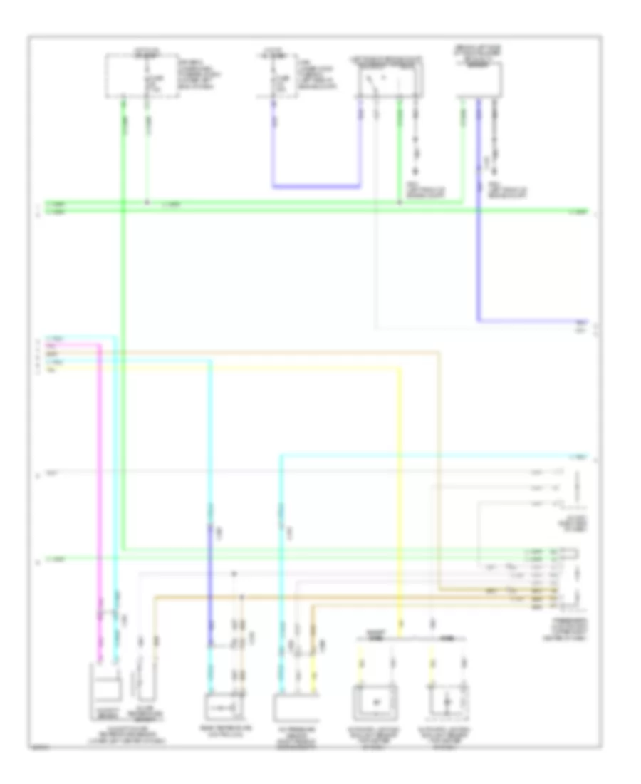
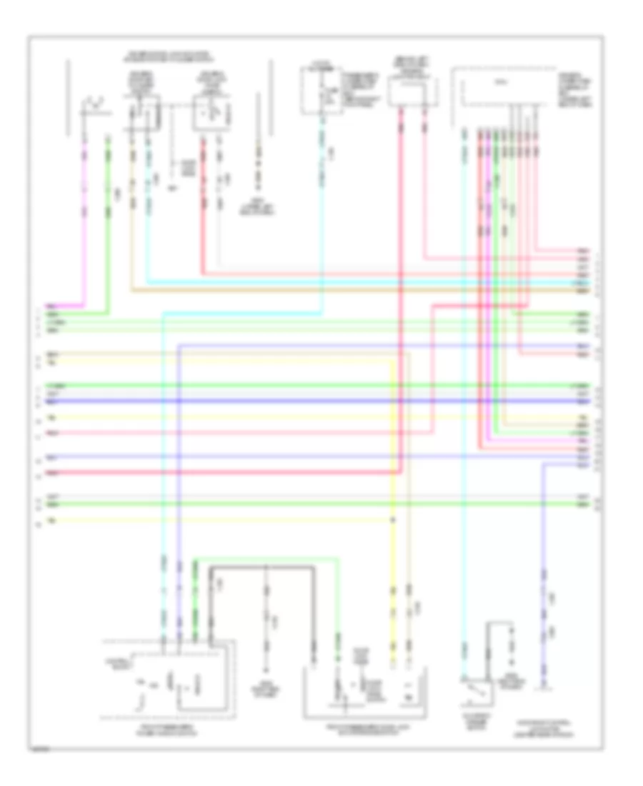
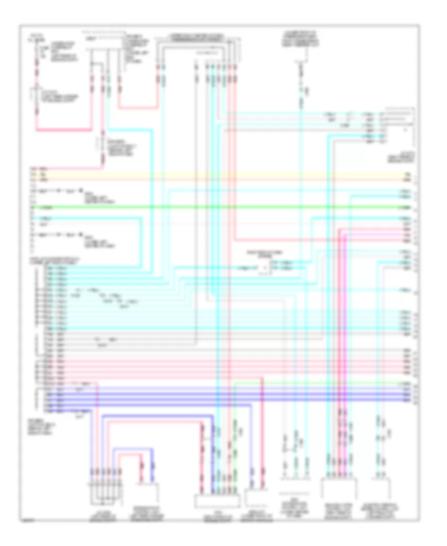
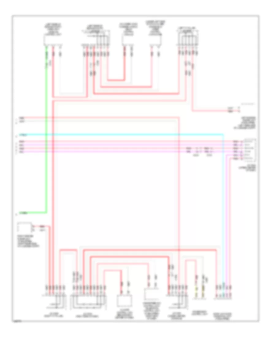
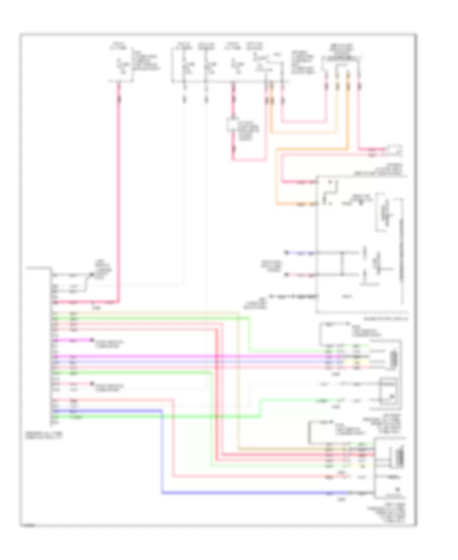
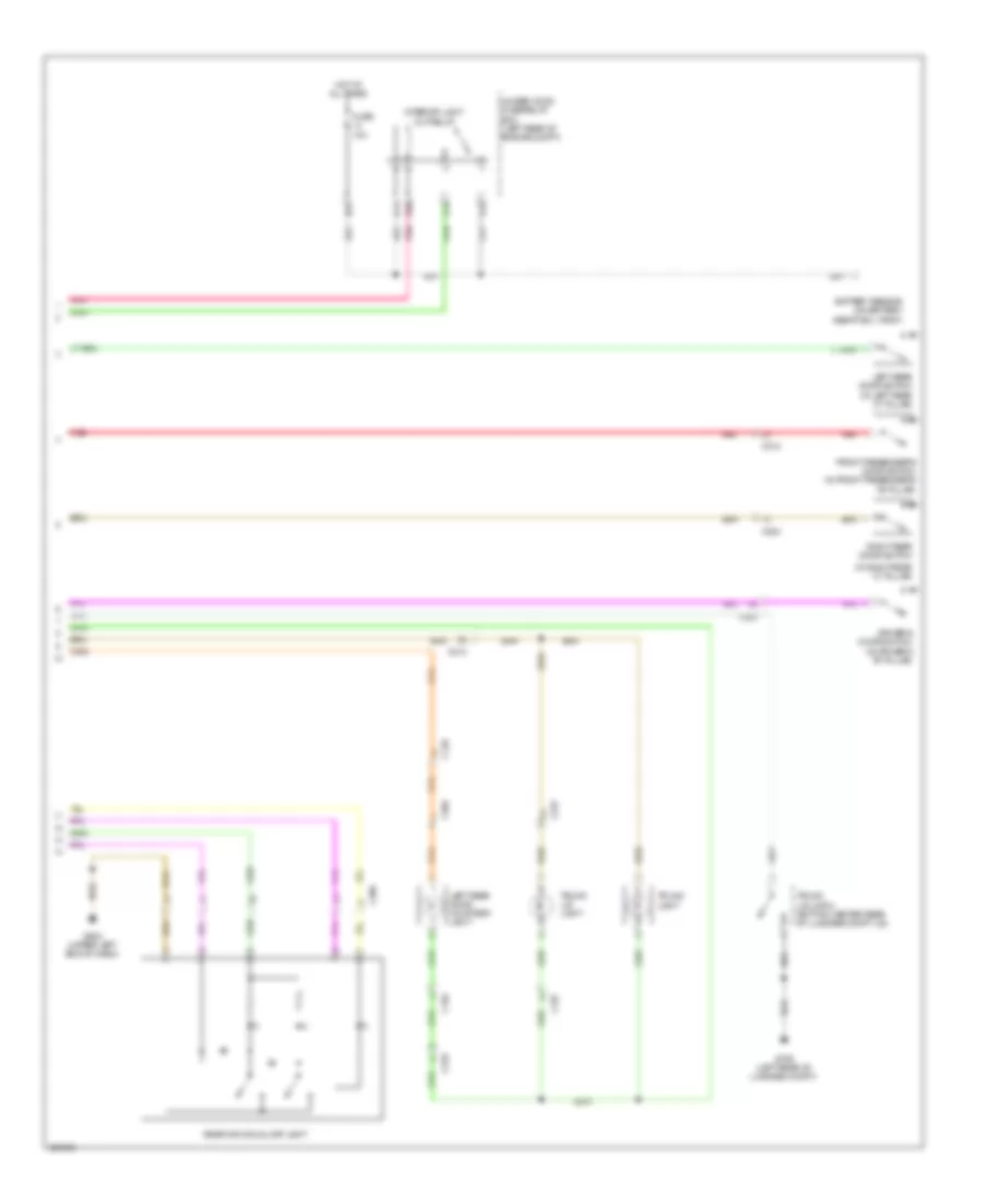
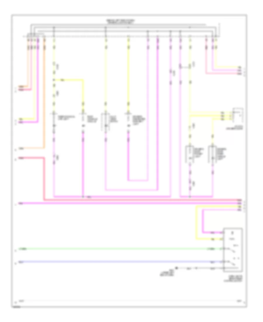
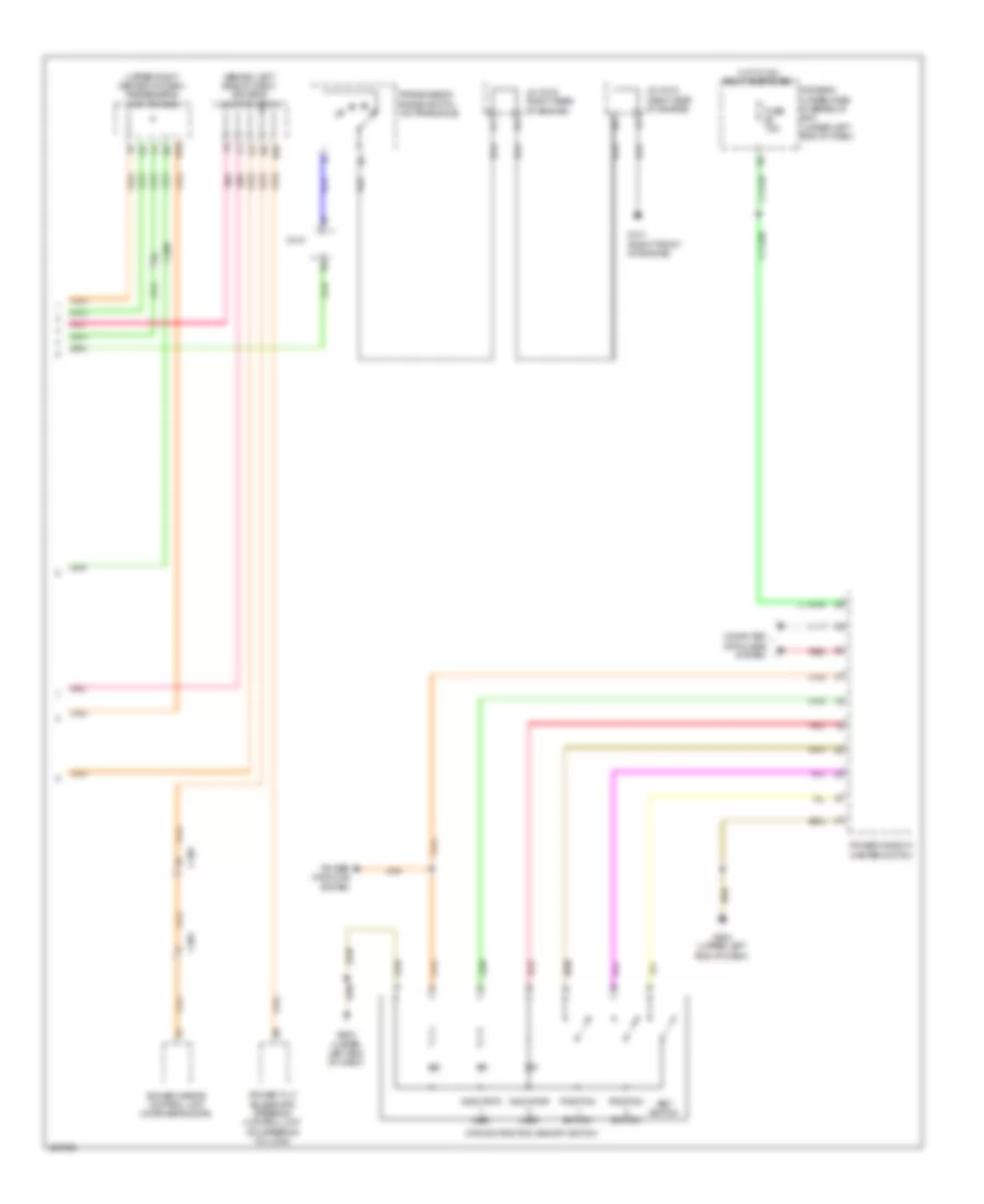
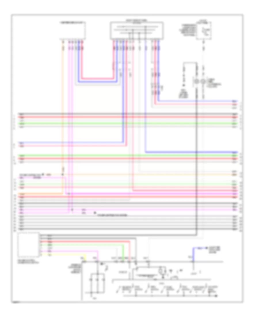
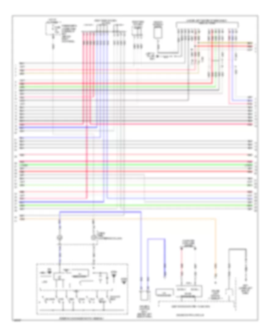
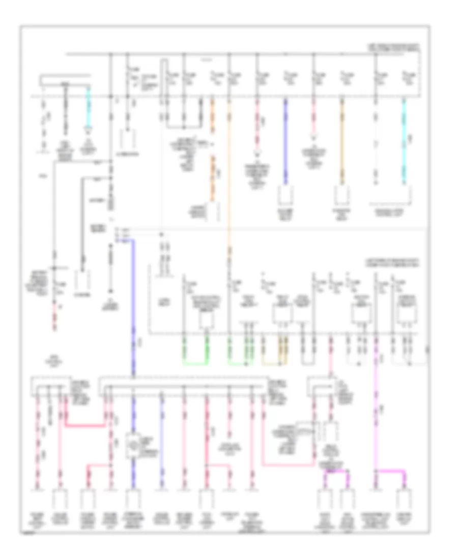
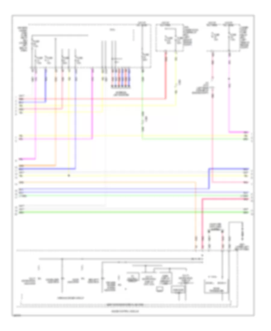
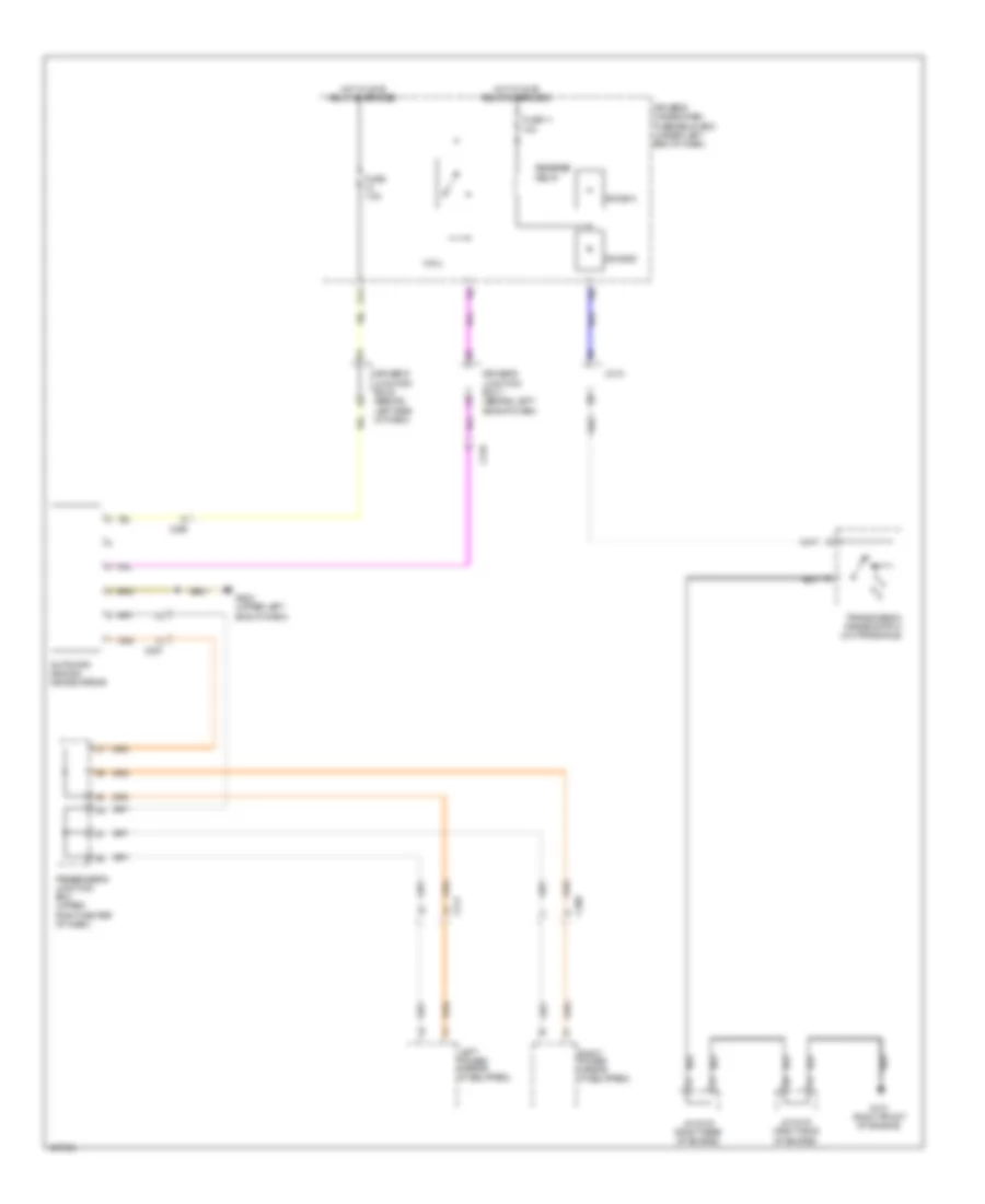
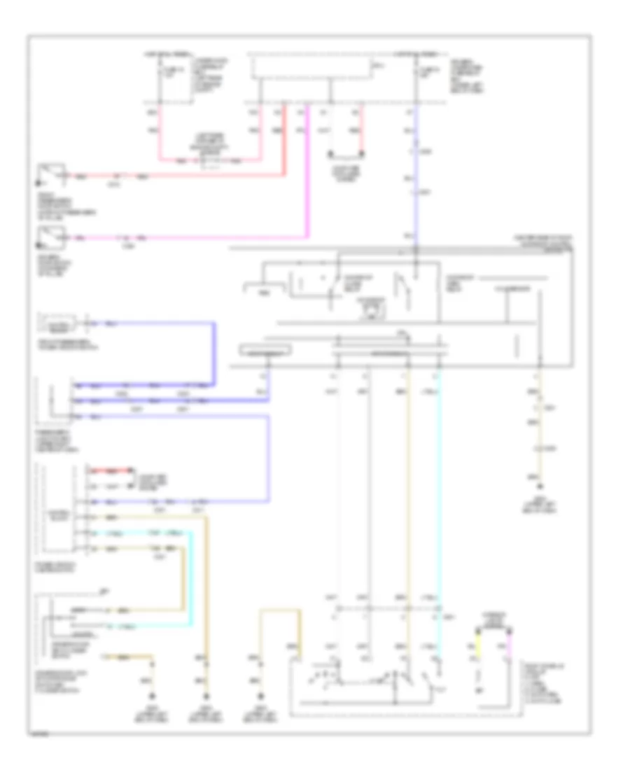
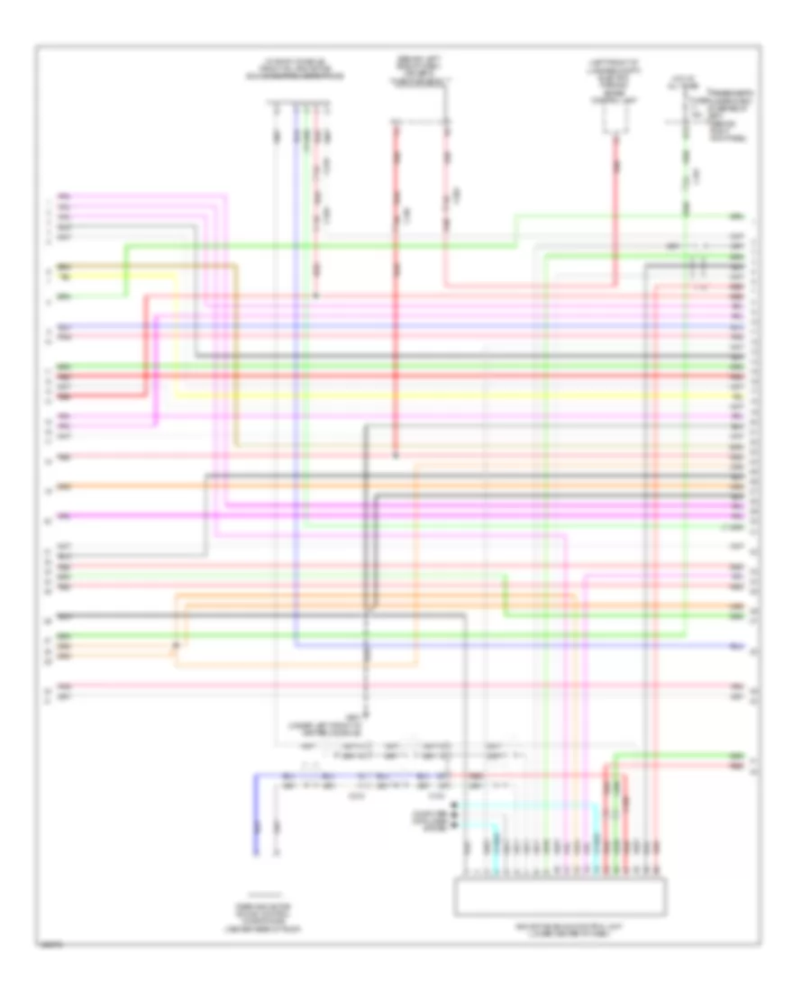
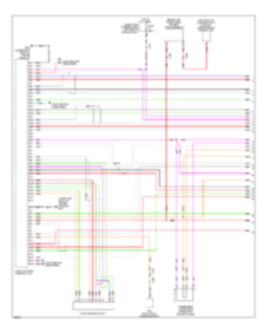
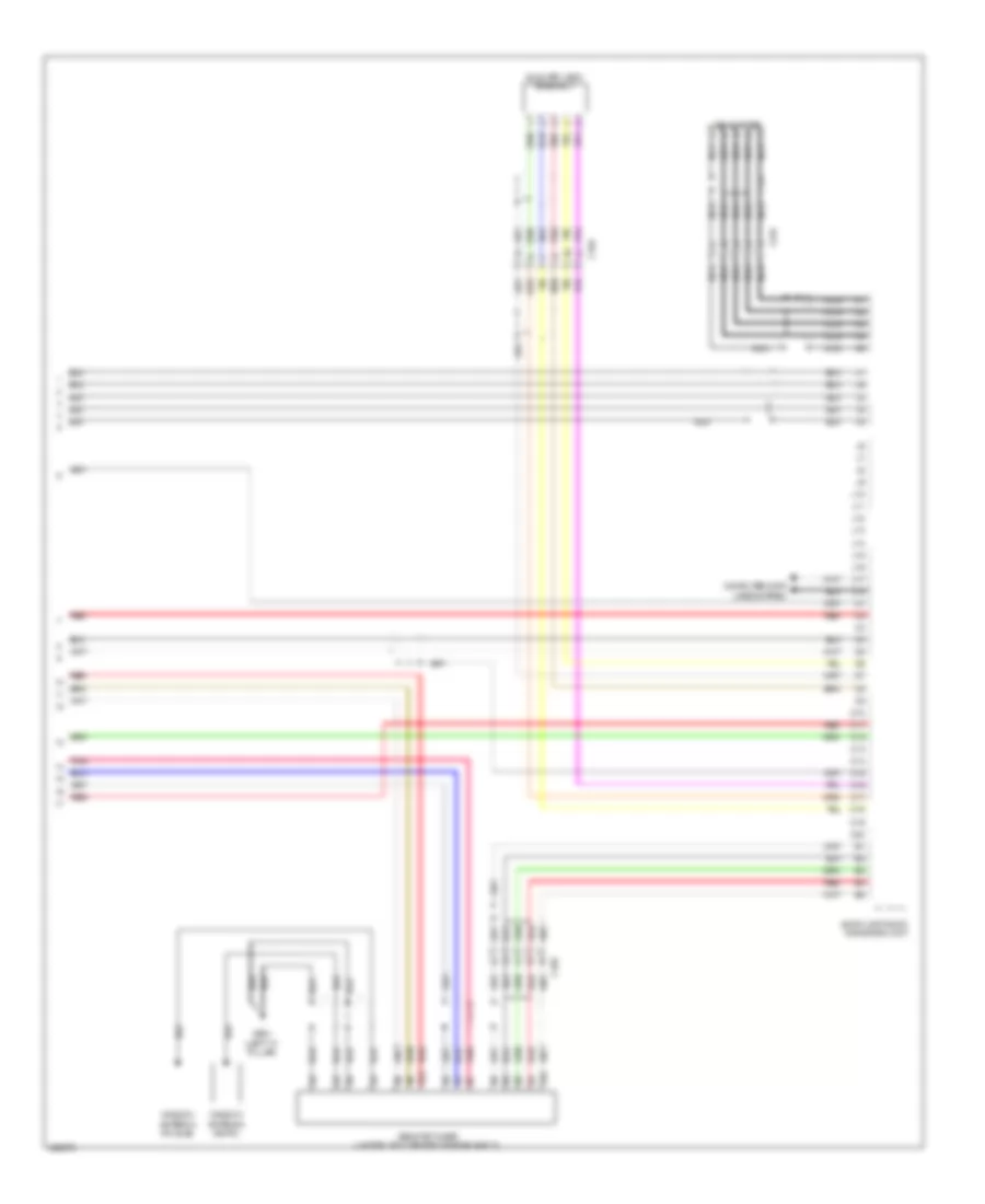
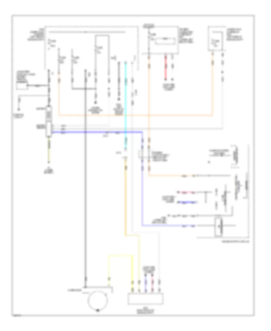
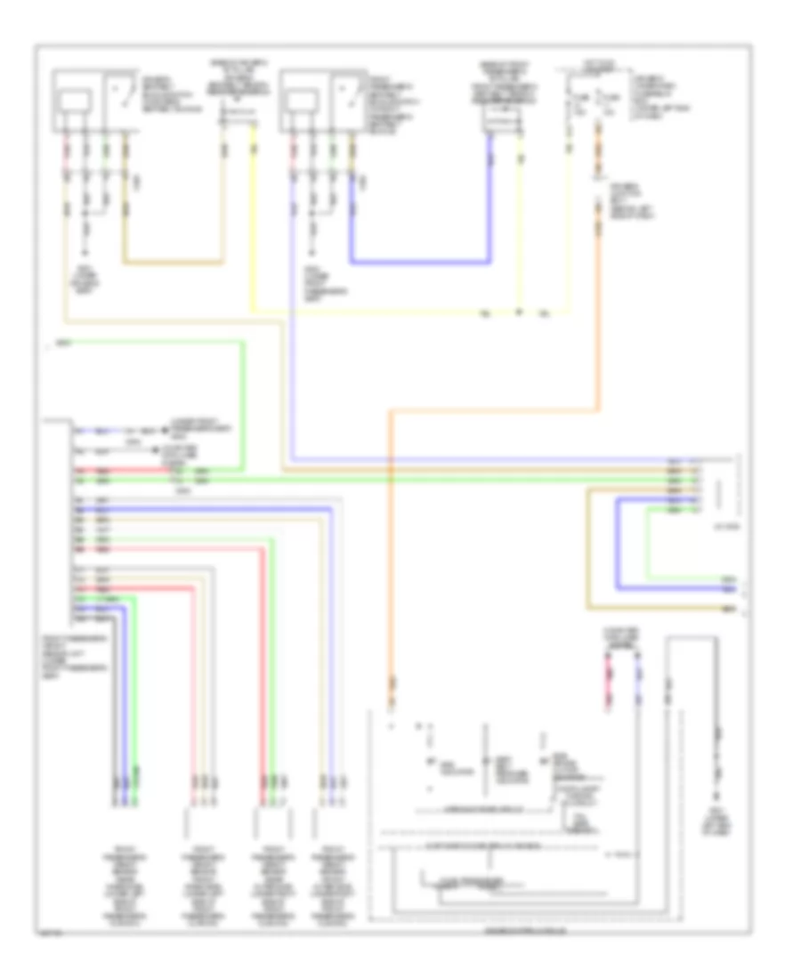
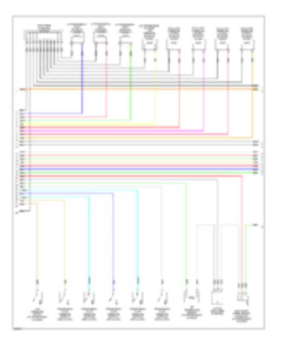
Automatic A/C Wiring Diagram (2 of 4) for Acura RLX 2014
List of elements for Automatic A/C Wiring Diagram (2 of 4) for Acura RLX 2014:
- (left side of engine compt) radiator fan relay
- A10
- A14
- A20
- A23
- A31
- B15
- B16
- B45
- C401
- C48
- Computer data lines system
- E20
- E21
- E49
- E50
- E75
- E95
- E96
- Ect sensor 1 (top left rear of engine)
- Ect sensor 2 (on lower radiator outlet)
- Engine controls system
- Fuse 15a
- Fuse 2-2 60a
- Fuse 2-4 50a
- Fuse 7.5a
- Hot at all times
- J/c c016 (right rear of engine)
- J/c c018 (left rear corner of engine compt)
- Main under-hood fuse box (left side of engine compt)
- Outside air temperature sensor (behind left side of front bumper)
- Pcm (right front of engine compt)
- Pgm-fi sub relay
- Pnk
- Red
- Relay control module (in under-hood fuse/relay box)
- Under-hood fuse/relay box (left rear of engine compt)
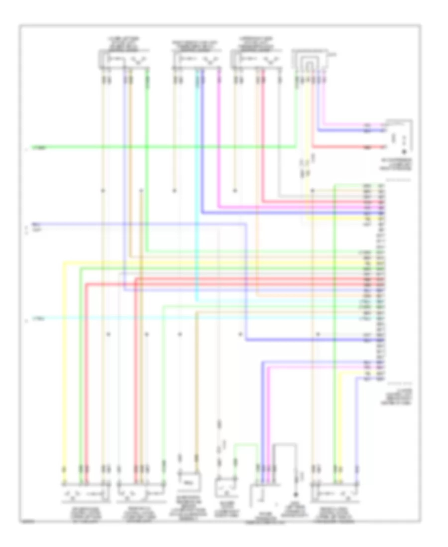
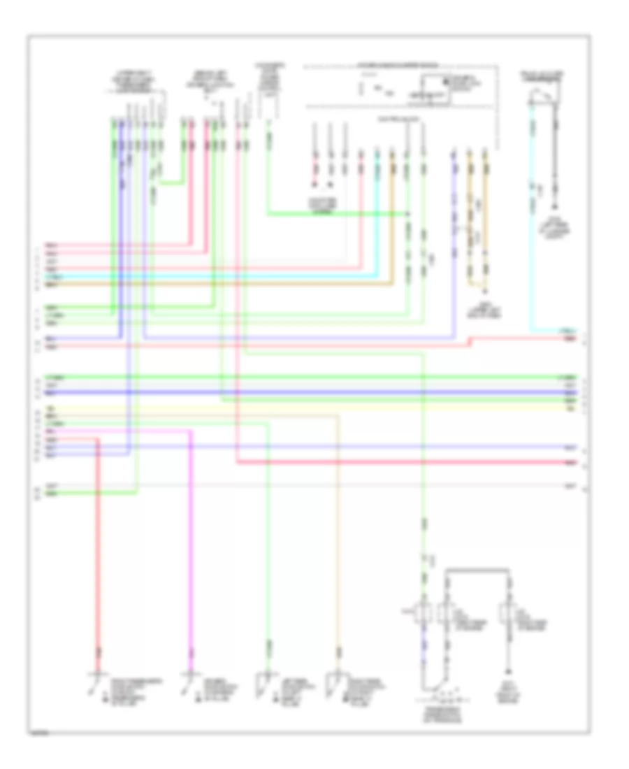
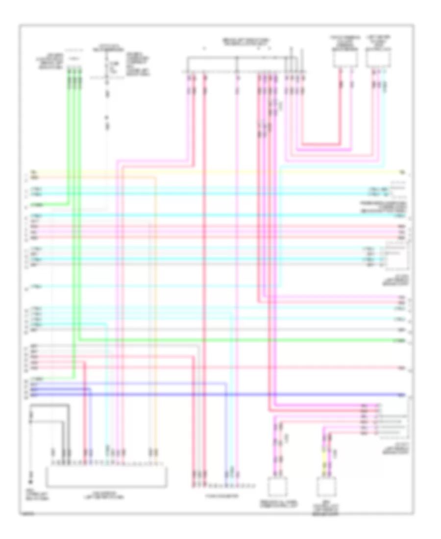
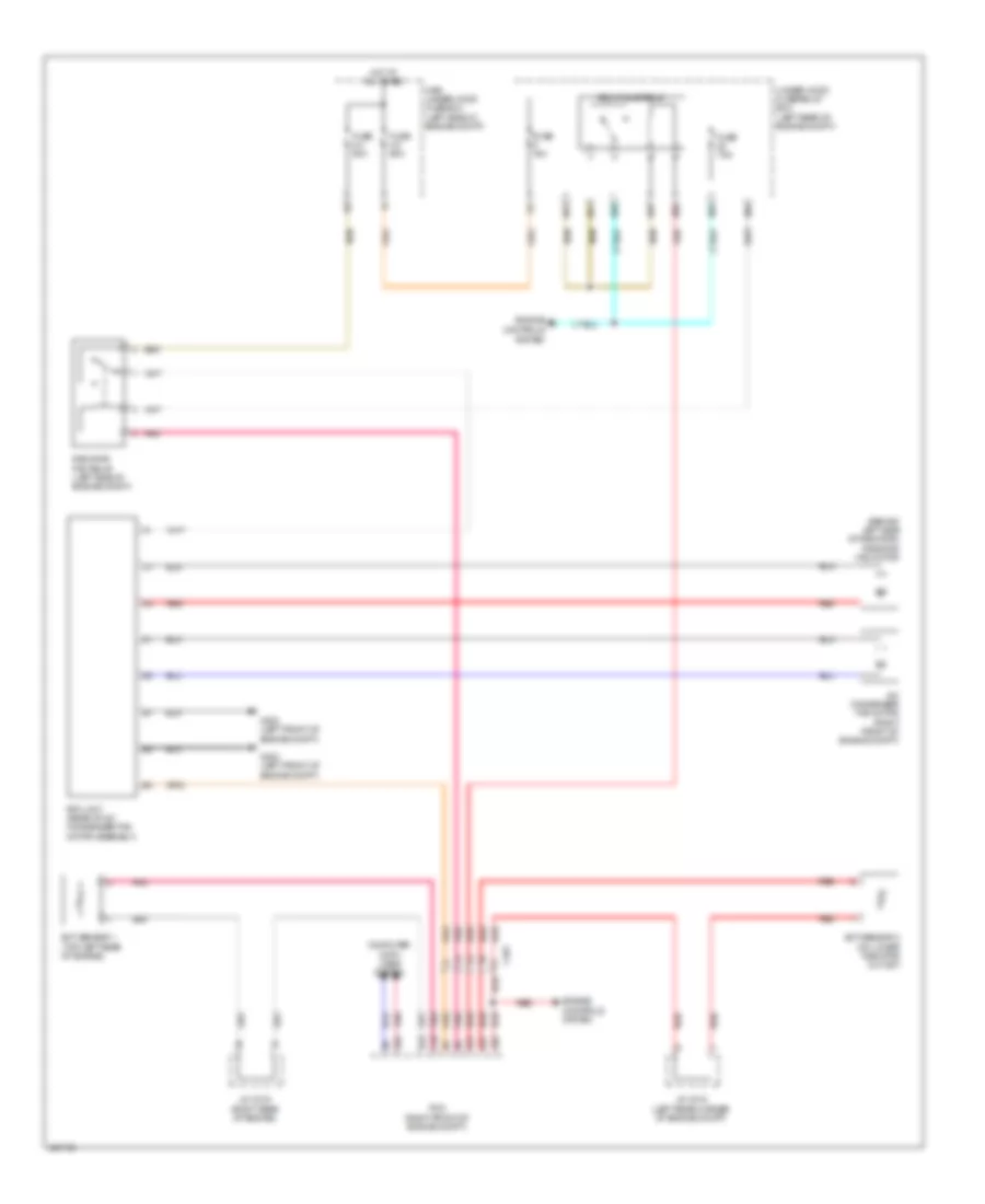
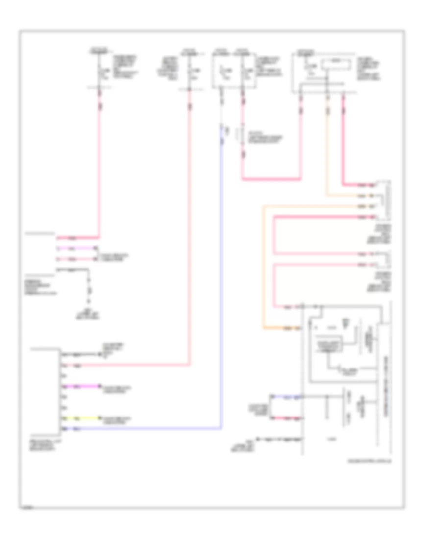
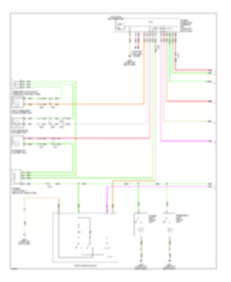
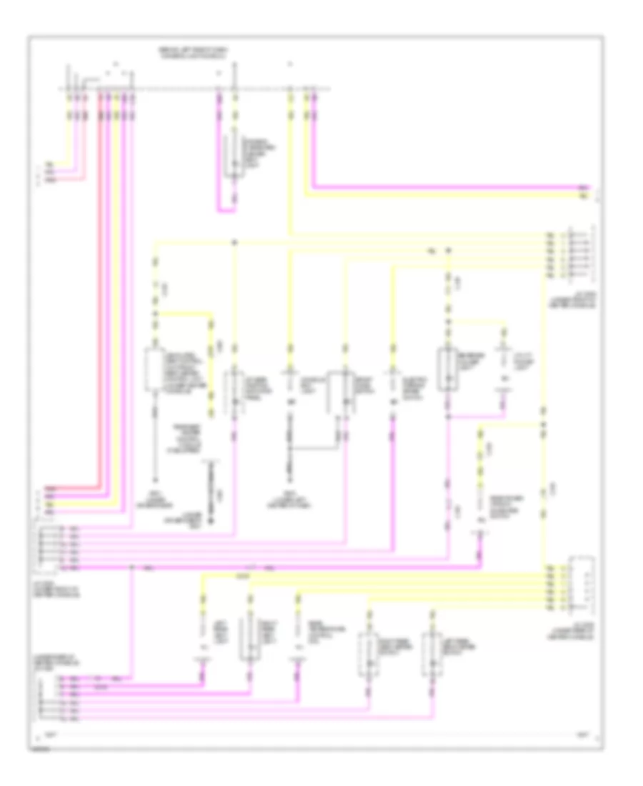
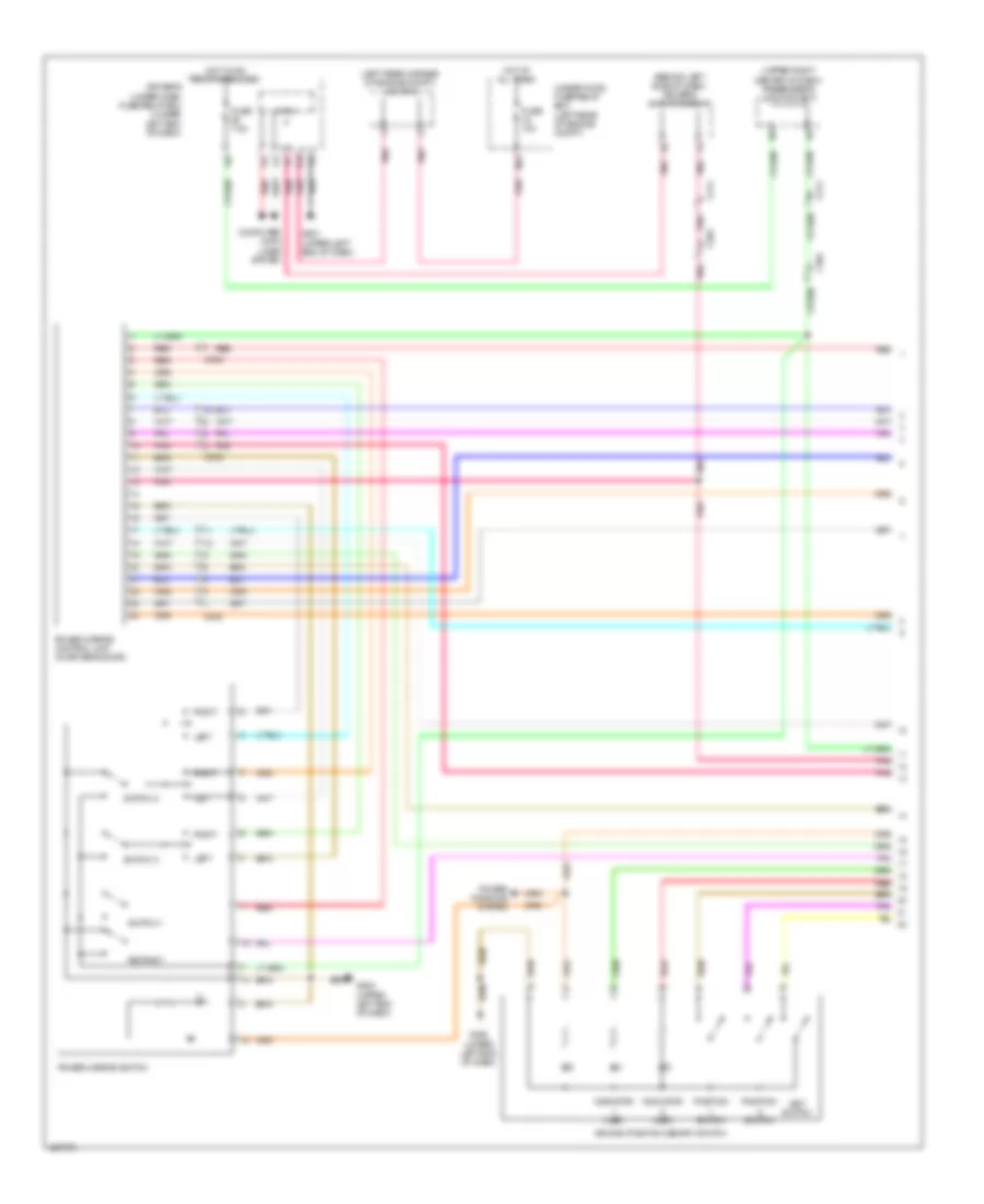
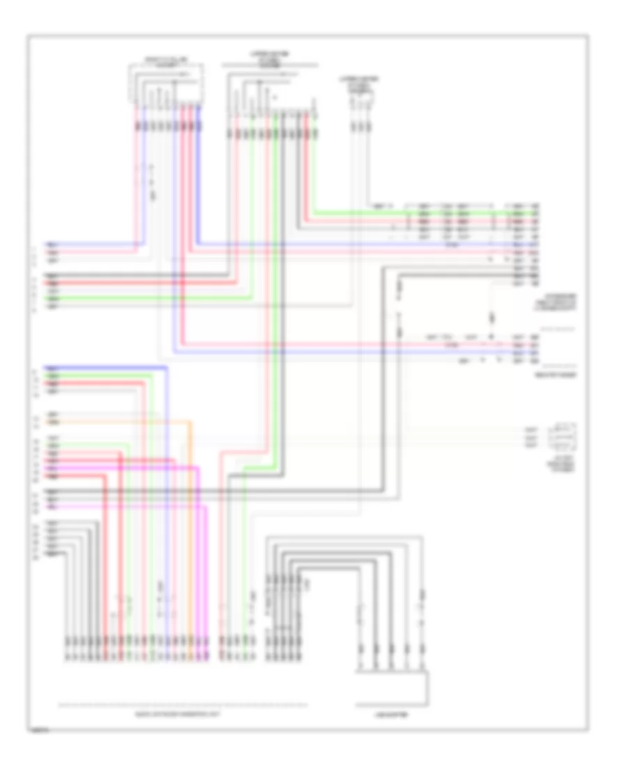
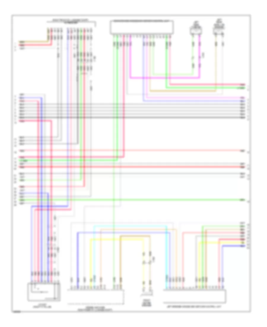
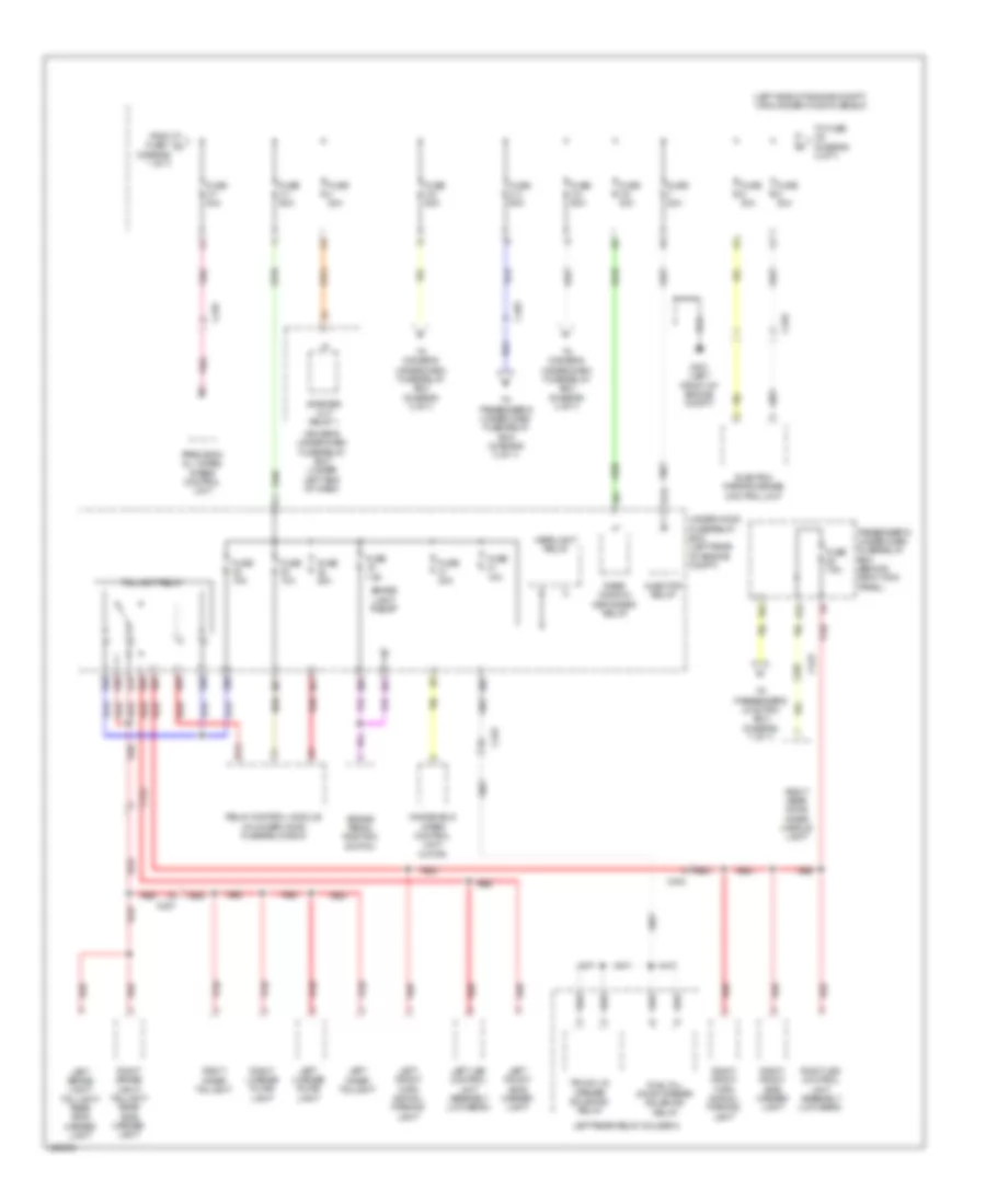
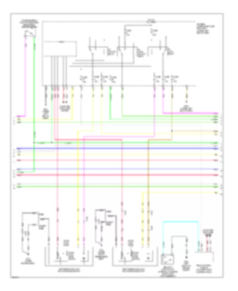
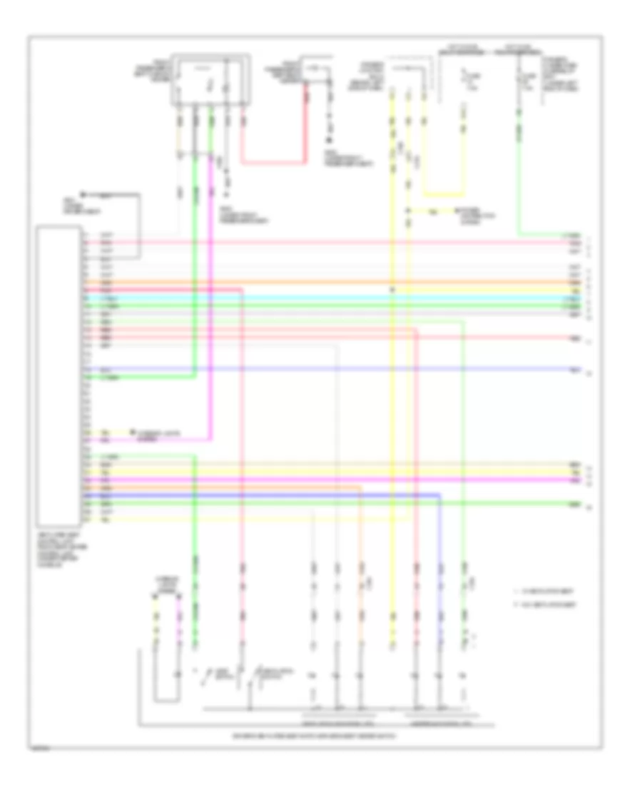
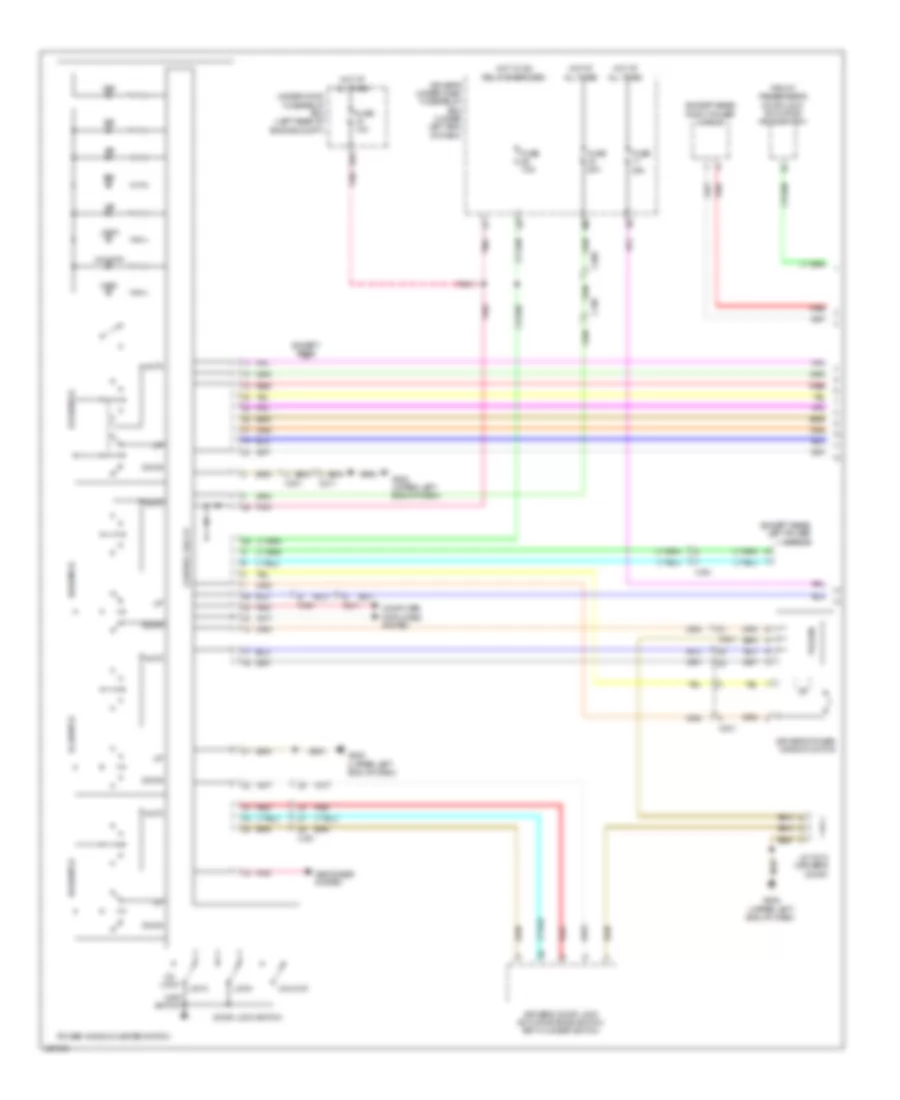
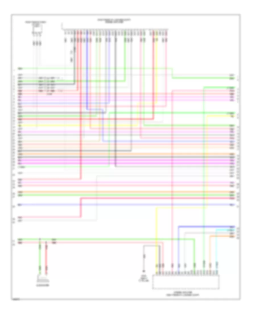
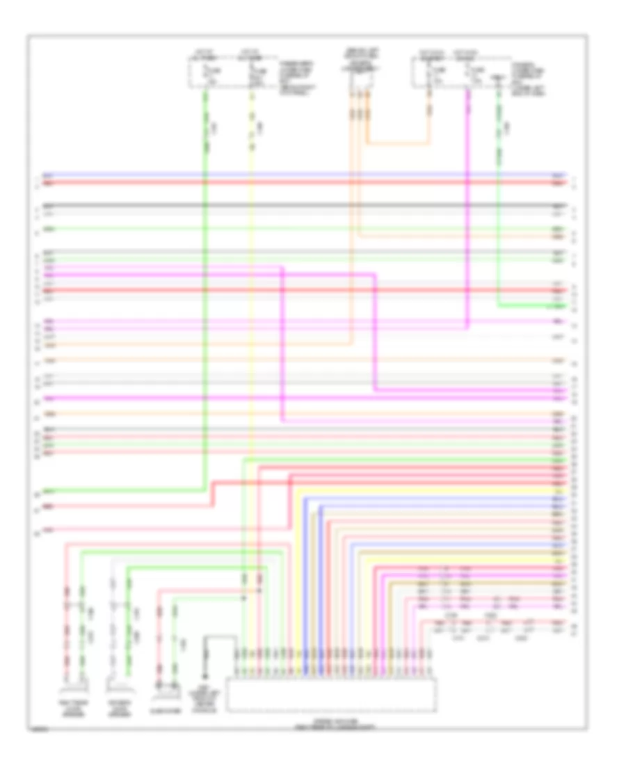
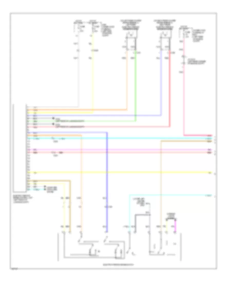
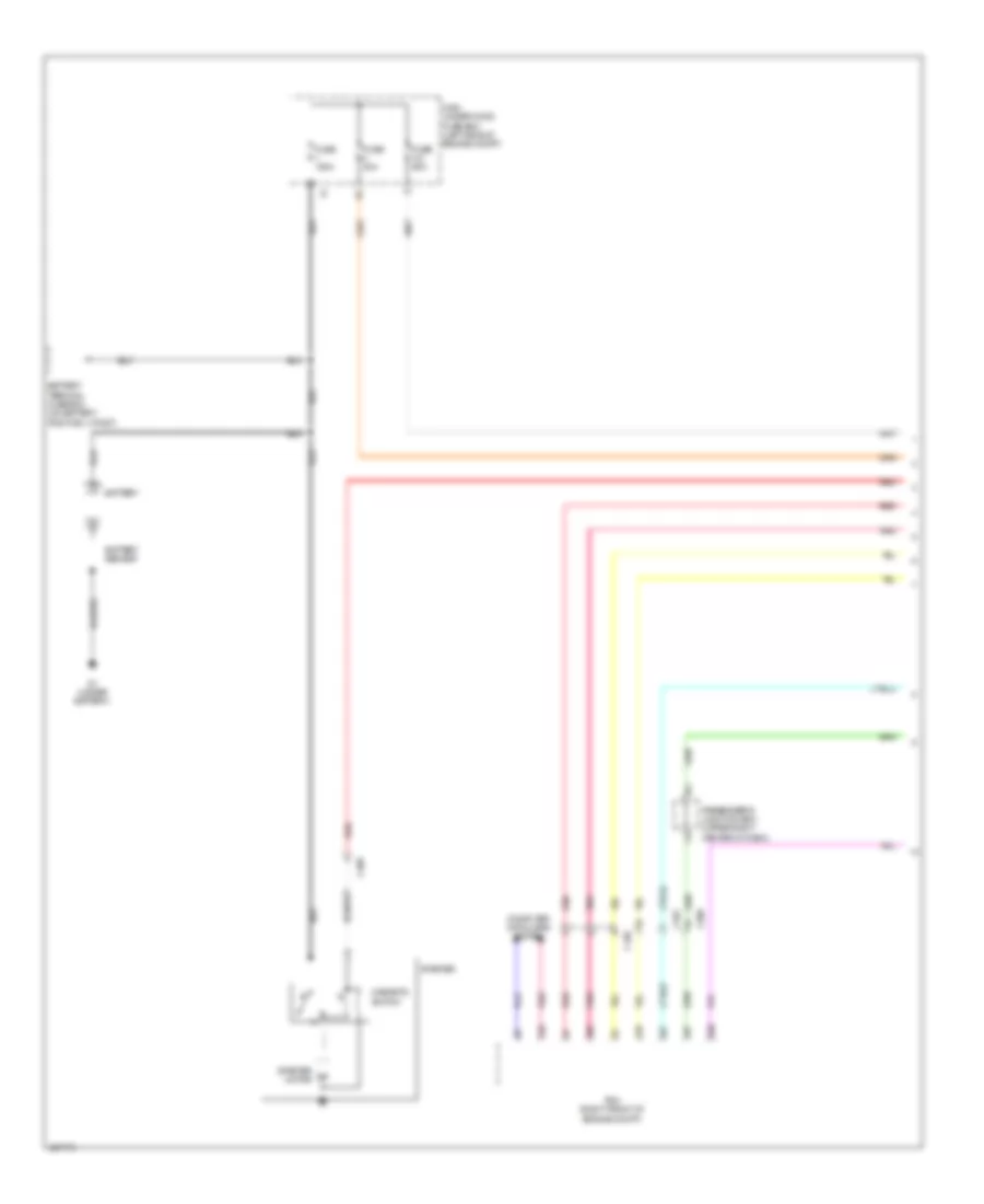
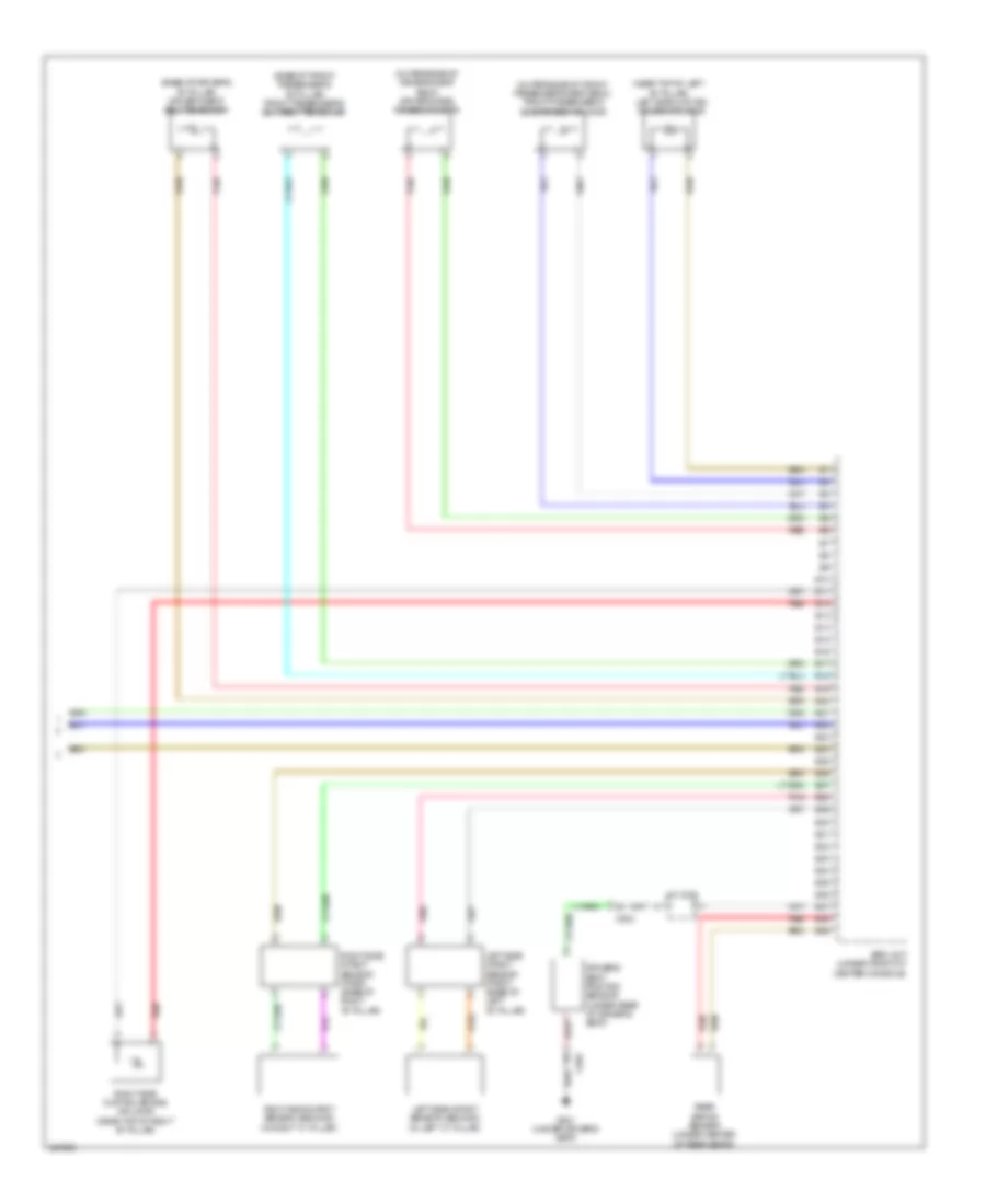
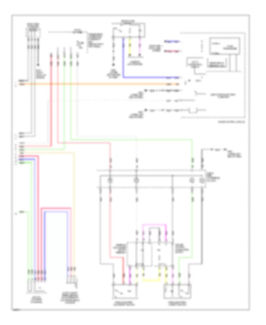
Automatic A/C Wiring Diagram (3 of 4) for Acura RLX 2014
List of elements for Automatic A/C Wiring Diagram (3 of 4) for Acura RLX 2014:
- (behind left side of front bumper) air quality sensor
- (left side of engine compt) blower motor relay
- A/c pressure sensor (right rear of engine compt)
- Automatic lighting/ sunlight sensor (top center of dash)
- Base
- C101
- C105
- C206
- C216
- C404
- C415
- Driver's under-dash fuse/relay box (under left end of dash)
- Except base
- F13
- Fuse 2-8 40a
- Fuse 7.5a
- G301 (left front of engine compt)
- Hot at all times
- Hot in on or start
- Humidity sensor
- Humidity/in-car temperature sensor (lower left center of dash)
- In-car temperature sensor
- J/c c001 (right end of dash)
- Main under-hood fuse box (left side of engine compt)
- Passenger's junction box (upper right center of dash)
- Rear temperature control dial
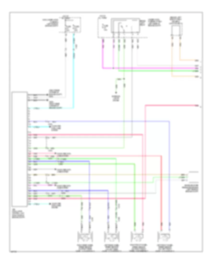
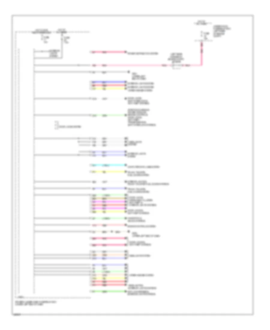
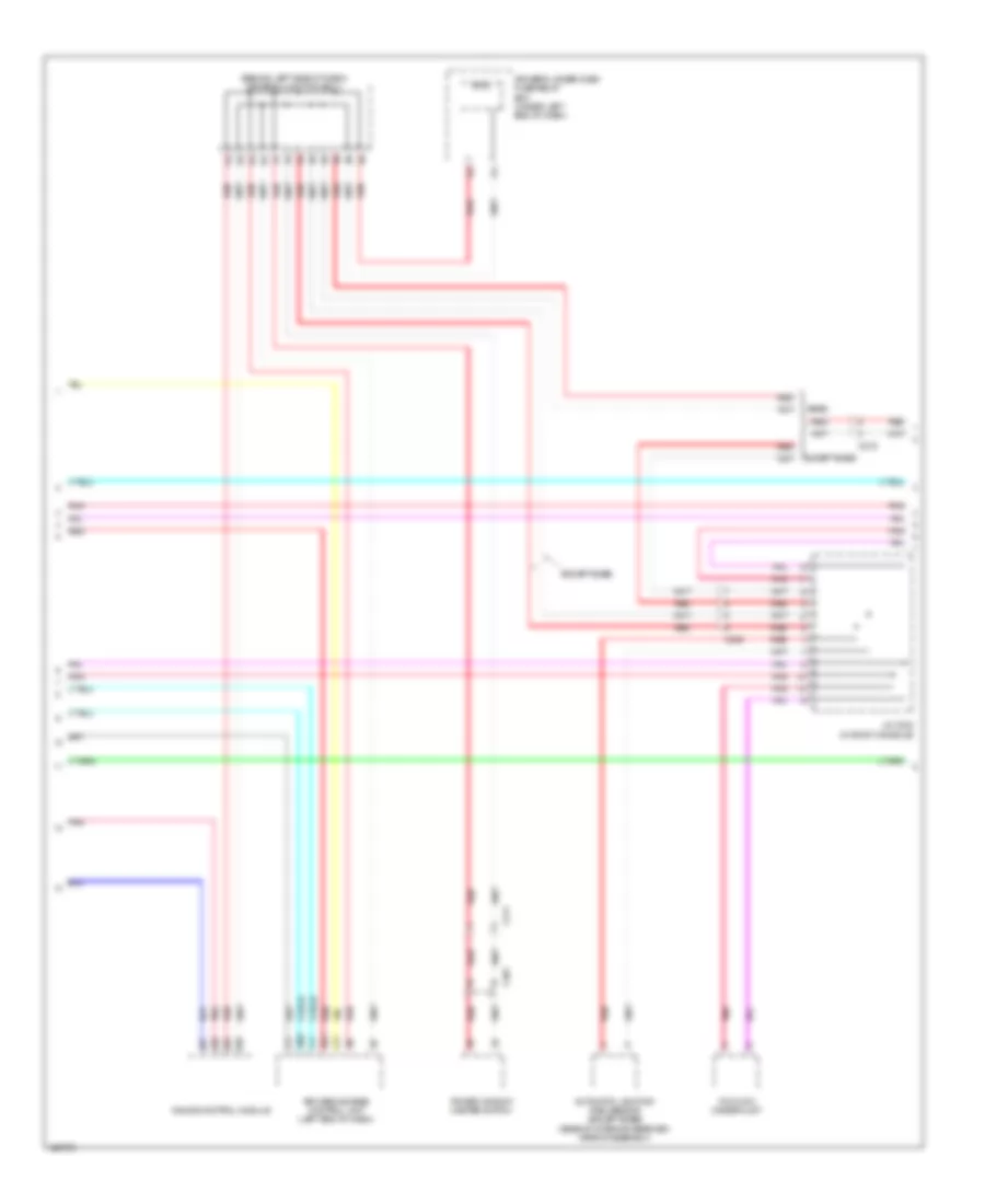
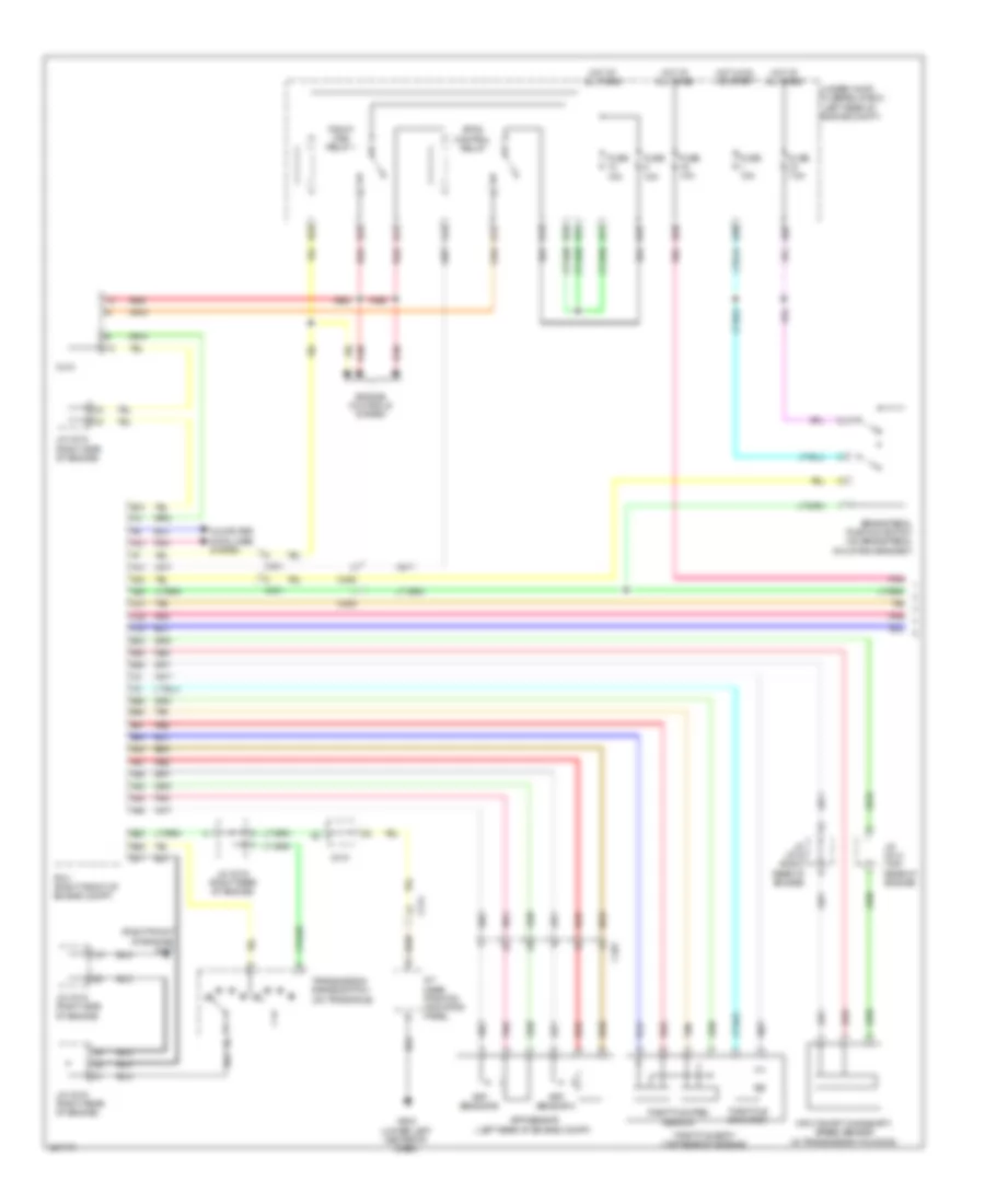
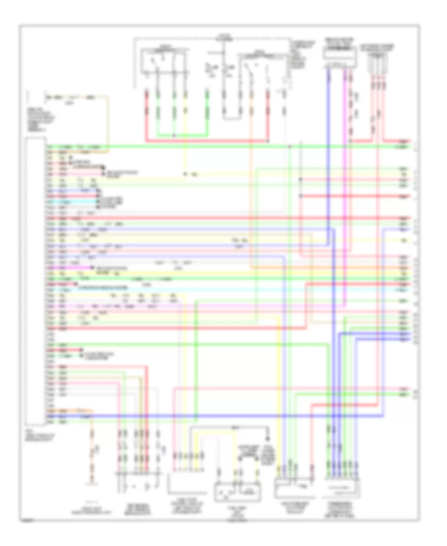
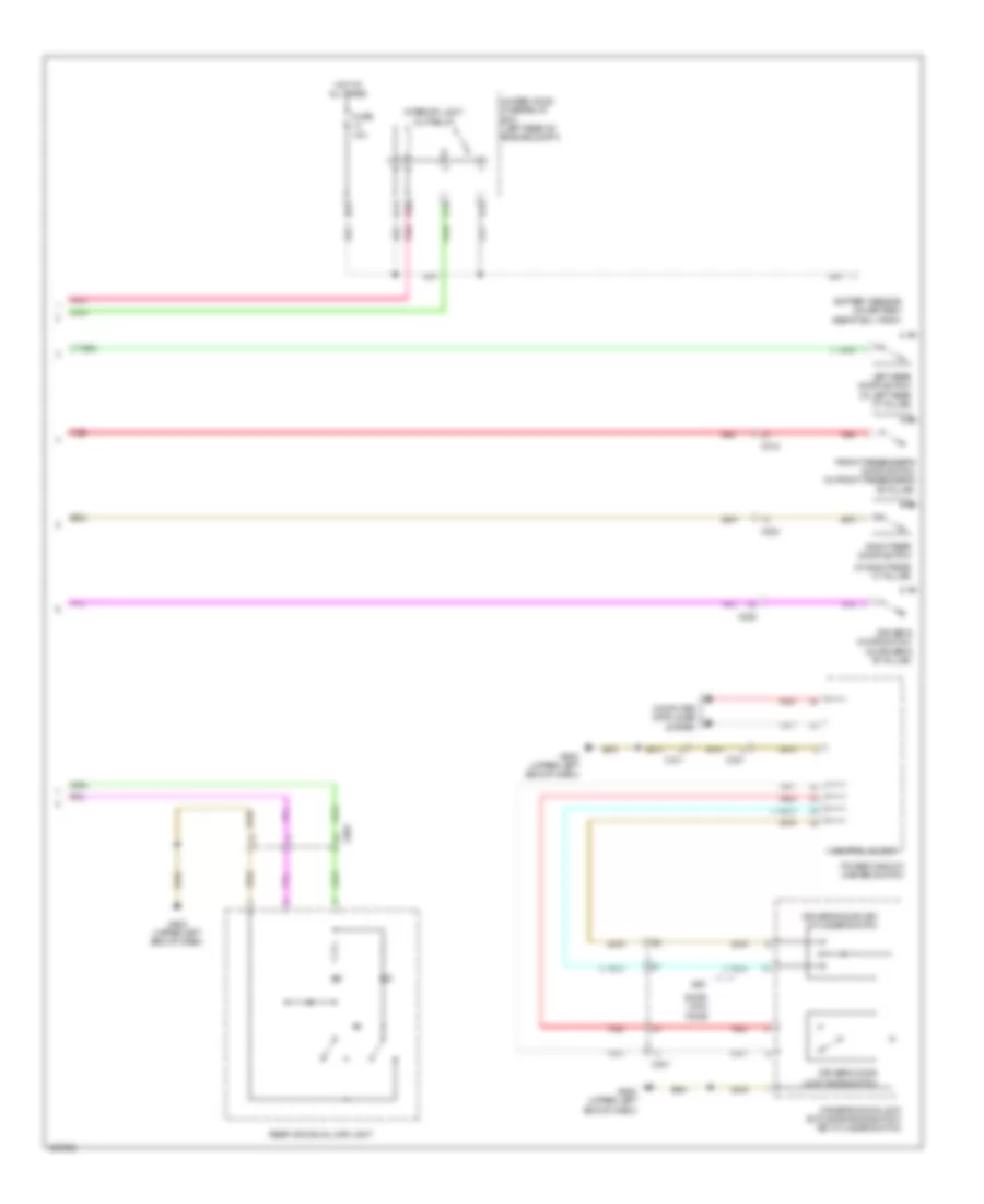
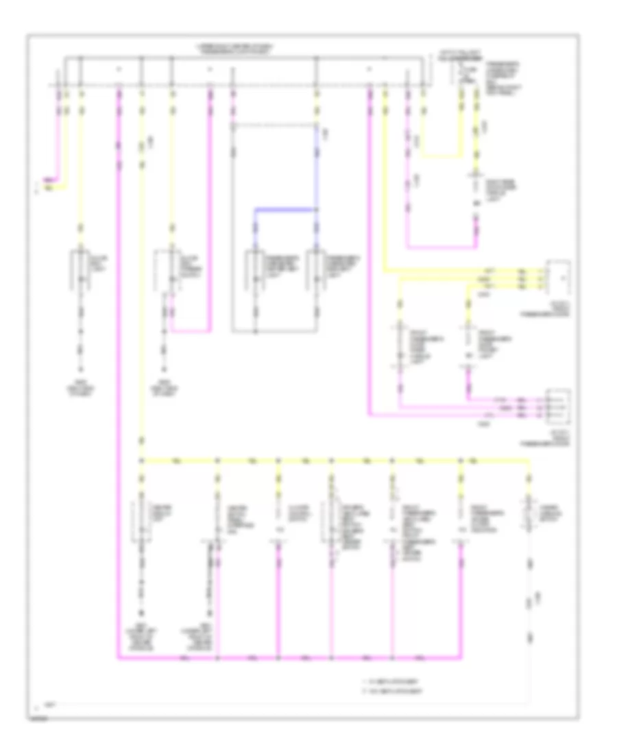
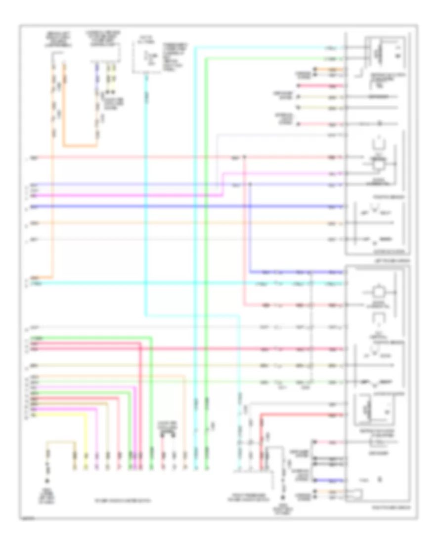
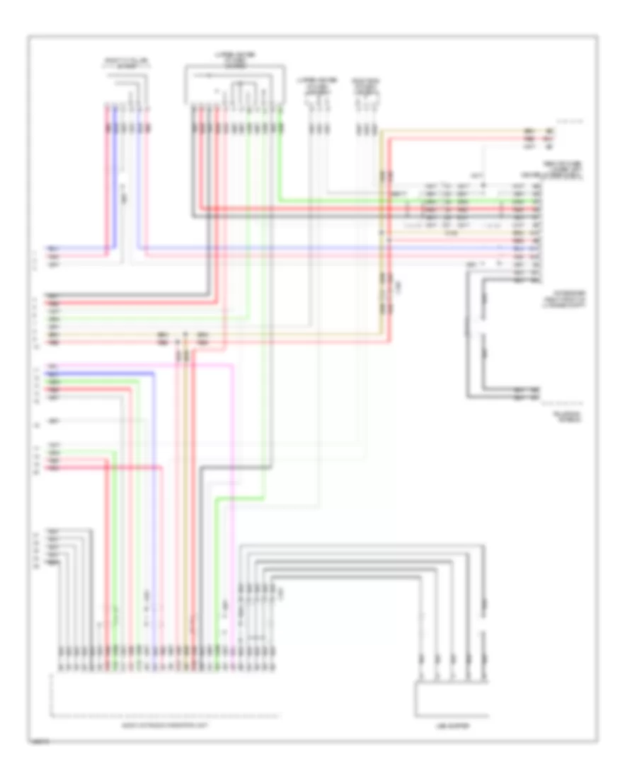
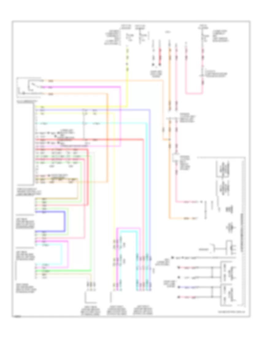
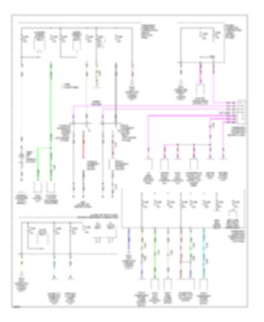
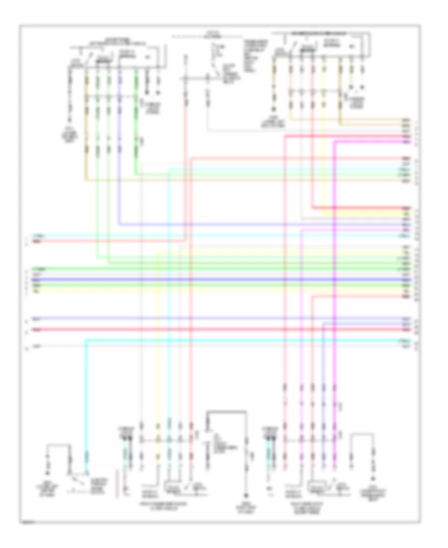
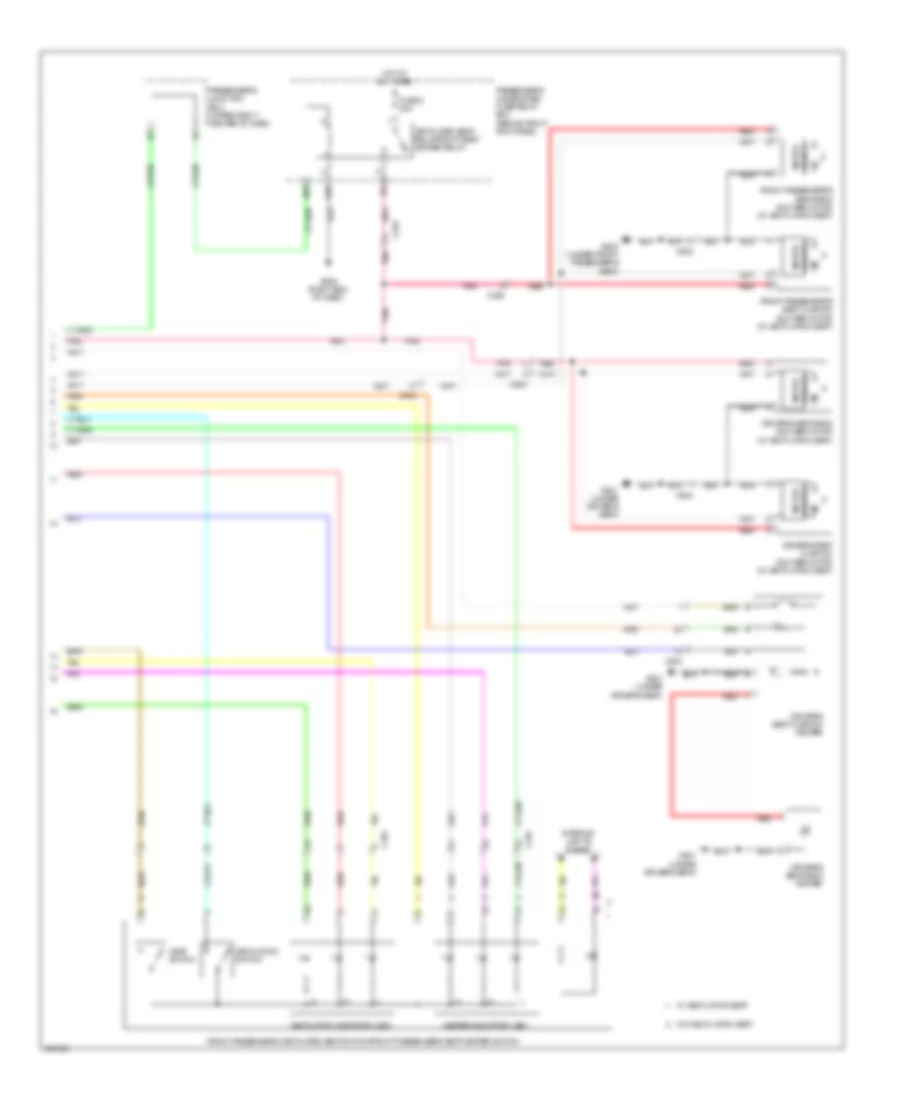
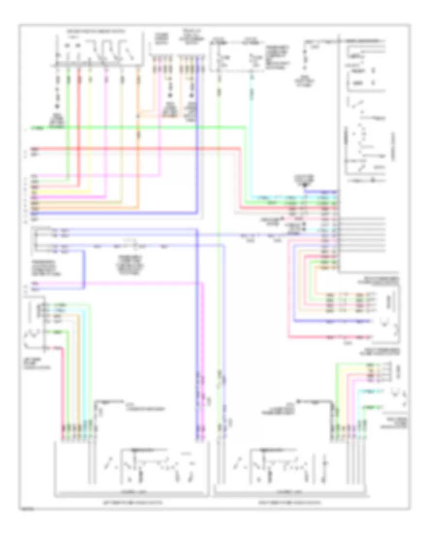
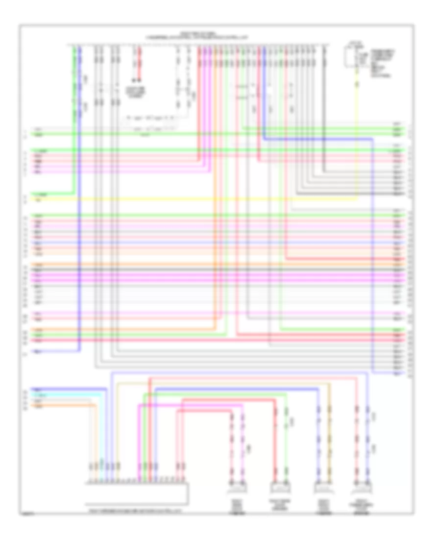
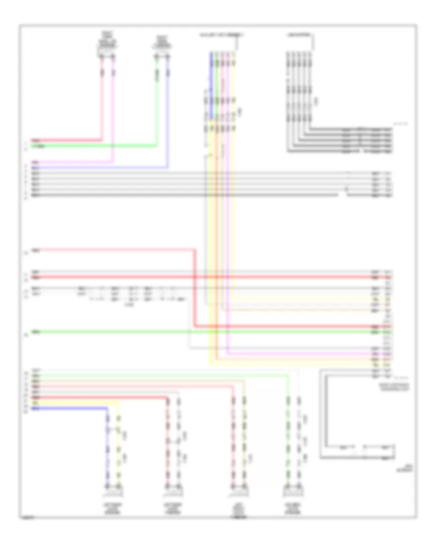
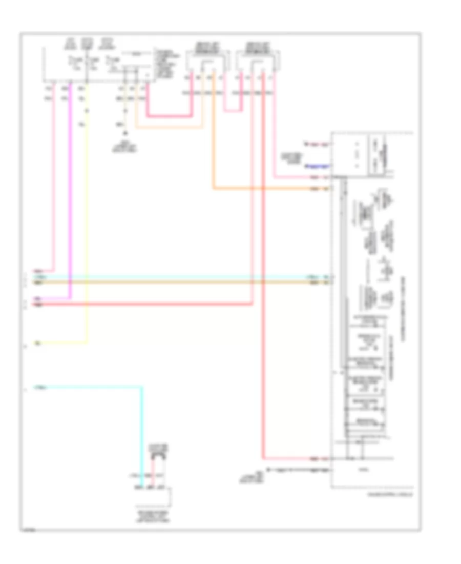
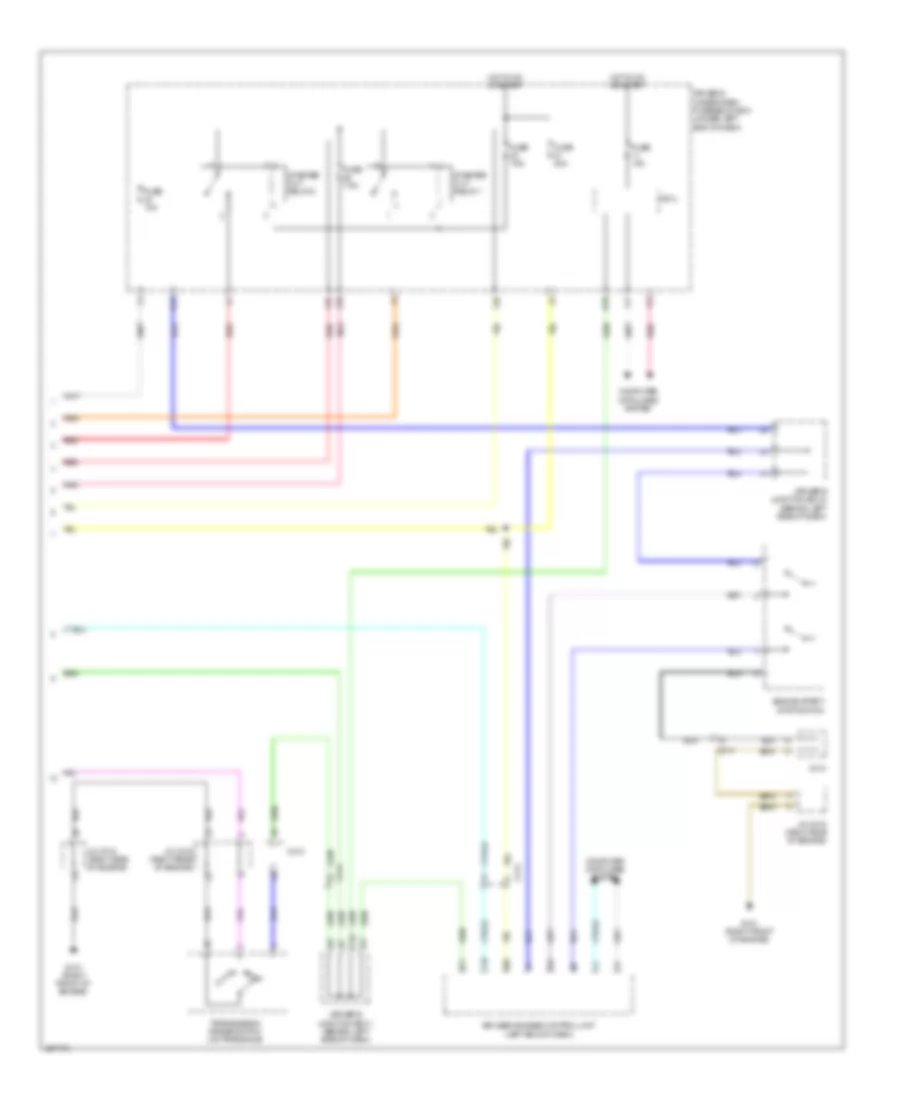
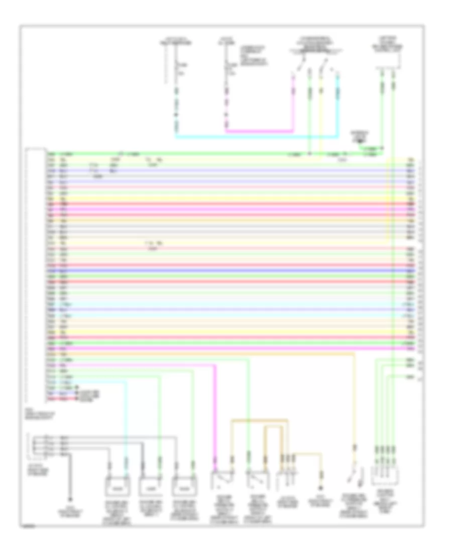
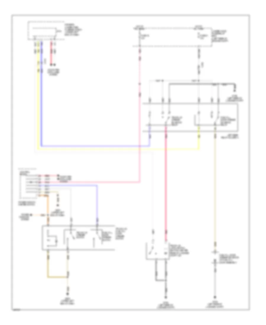
Automatic A/C Wiring Diagram (4 of 4) for Acura RLX 2014
List of elements for Automatic A/C Wiring Diagram (4 of 4) for Acura RLX 2014:
- (lower left side of hvac unit) driver's air mix control motor
- (right side of hvac unit) passenger's air mix control motor
- (upper right side of hvac unit) passenger's mode control motor
- A/c compressor (lower left front of engine)
- B10
- B11
- B12
- B13
- B14
- B15
- B16
- B17
- B18
- B19
- B20
- B21
- B22
- B23
- B24
- B25
- B26
- B27
- B28
- B29
- B30
- B31
- B32
- B33
- B34
- B35
- B36
- Blower motor (under right side of dash)
- C410
- C414
- C415
- Climate control unit (behind right center of dash)
- Driver's mode control motor (upper left side of hvac unit)
- Evaporator temperature sensor (lower right side of hvac evaporator assembly)
- G402 (left rear corner of engine compt)
- Pnk
- Power transistor (near blower motor)
- Rear air mix control motor (lower right side of hvac unit)
- Recirculation control motor (upper left side of hvac blower housing)
- Red
ANTI-LOCK BRAKES
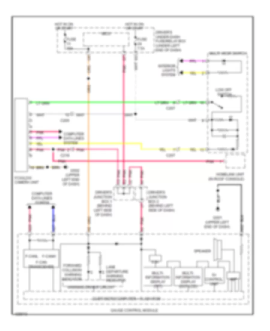
Anti-lock Brakes Wiring Diagram (1 of 2) for Acura RLX 2014
List of elements for Anti-lock Brakes Wiring Diagram (1 of 2) for Acura RLX 2014:
- (behind left side of dash) driver's junction box 1
- (right rear corner of engine compt) g202
- Brake booster pressure sensor (left rear of engine compt)
- Brake light relay
- C206
- C213
- C237
- C238
- C402
- C404
- Computer data lines system
- E24
- E25
- E26
- E53
- E54
- E86
- Exterior lights system
- Fuse 2-3 30a
- Fuse 2-7 40a
- Fuse 7.5a
- G202 (right rear corner of engine compt)
- Hot at all times
- Left front wheel speed sensor (on left front wheel hub assembly)
- Left rear wheel speed sensor (on left rear wheel hub assembly)
- Main under-hood fuse box (left side of engine compt)
- Nca
- Pnk
- Red
- Right front wheel speed sensor (on right front wheel hub assembly)
- Right rear wheel speed sensor (on right rear wheel hub assembly)
- Under-hood fuse/relay box (left rear of engine compt)
- Vsa modulator control unit (right side of engine compt)
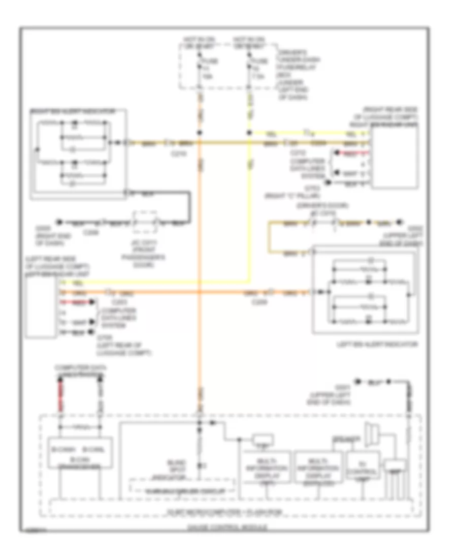
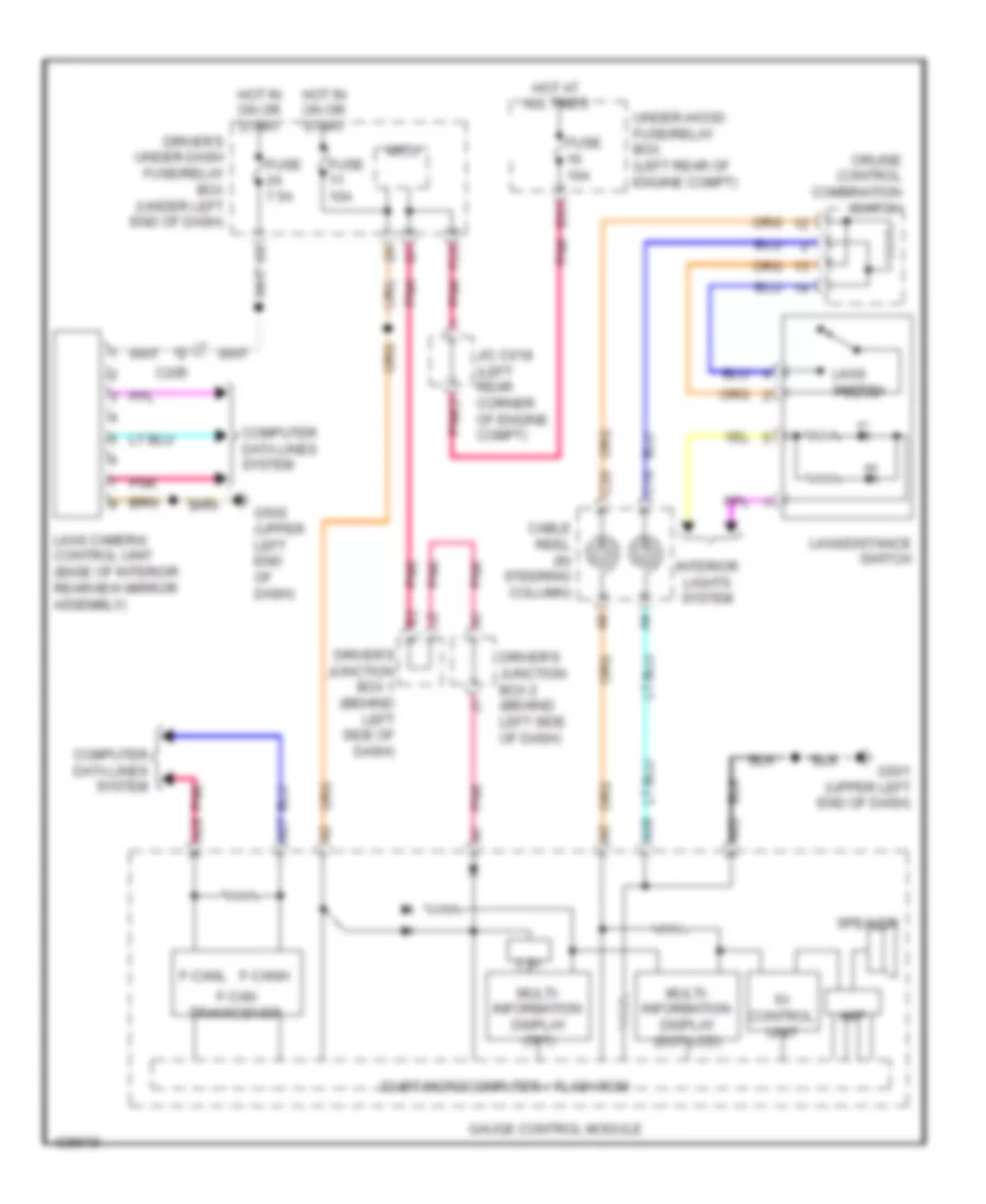
Anti-lock Brakes Wiring Diagram (2 of 2) for Acura RLX 2014
List of elements for Anti-lock Brakes Wiring Diagram (2 of 2) for Acura RLX 2014:
- (behind left side of dash) driver's junction box 2
- (tft) display information multi
- 3.3v
- 32bit microcomputer + flash rom
- 5v control circuit
- 8mb/32mb flash
- A11
- A12
- A25
- A27
- A28
- A32
- Abs ind
- Brake fluid level switch (on brake fluid reservoir)
- Brake ind
- Brake pedal position switch (on brake pedal mounting bracket)
- Brake system ind
- C203
- C214
- C406
- Circuit fail-safe
- Circuit turning-on compulsory
- Cmbs ind
- Computer data lines system
- Display (dot lcd)
- Driver's under-dash fuse/relay box (under left end of dash)
- E26
- Electric parking brake control unit (left front of luggage compt)
- Electric parking brake switch
- F-can h
- F-can l
- Fuse 10a
- Fuse 7.5a
- G401 (left rear corner of engine compt)
- G501 (upper left end of dash)
- G502 (upper left end of dash)
- G503 (lower left center of dash)
- Gauge control module
- Hot in on or start
- Keyless access control unit (left end of dash)
- Multi information
- Multi visor switch
- Passenger's under-dash fuse/relay box (behind right kick panel)
- Pcm (right front of engine compt)
- Pnk
- Red
- Steering angle sensor (top of steering column)
- Transceiver f can
- Vsa ind
- Vsa off ind
- Vsa off switch
- Warning driver circuit
ANTI-THEFT
Anti-theft Wiring Diagram (1 of 7) for Acura RLX 2014
List of elements for Anti-theft Wiring Diagram (1 of 7) for Acura RLX 2014:
- (behind left center of rear bumper) keyless buzzer
- (upper right center of dash) passenger's junction box
- A10
- A18
- A25
- A27
- A37
- A38
- Acc relay
- C10
- C11
- C12
- C13
- C14
- C15
- C16
- C17
- C18
- C19
- C20
- C202
- C206
- C21
- C214
- C22
- C23
- C24
- C401
- Computer data lines system
- Driver's junction box 1 (behind left side of dash)
- Driver's junction box 2 (behind left side of dash)
- Electric steering lock (steering column)
- G501 (upper left end of dash)
- G502 (upper left end of dash)
- G706 (left rear of luggage compt)
- Ig1a relay
- Ig1b relay
- Ig2 relay
- Keyless access control unit (left end of dash)
- Park pin switch/ shift lock solenoid (base of shift lever assembly)
- Pcm (right front of engine compt)
- Pnk
- Red
- Under-dash sub-relay box (left side of dash)
Anti-theft Wiring Diagram (2 of 7) for Acura RLX 2014
List of elements for Anti-theft Wiring Diagram (2 of 7) for Acura RLX 2014:
- 3.3v
- 32bit microcomputer+flash rom
- 5v control circuit
- 8mb/32mb flash
- A25
- A26
- A32
- B-can h
- B-can l
- B-can transceiver
- C202
- C209
- Computer data lines system
- Door indicator
- Driver's under- dash fuse/ relay box (under left end of dash)
- E11
- E25
- E83
- E86
- Exterior lights system
- F11
- F12
- Fuse 10a
- Fuse 20a
- Fuse 3-4 30a
- Fuse 3-6 30a
- Fuse 7.5a
- G12
- G15
- G501 (upper left end of dash)
- Gauge control module
- Gear display (segment lcd)
- Hot at all times
- Immobilizer indicator
- J/c c018 (left rear corner of engine compt)
- Keyless access system indicator
- Main under-hood fuse/relay box (left side of engine compt)
- Micu
- Multi information indicator
- Multi- information display (dot lcd)
- Multi- information display (tft)
- Pnk
- Q19
- Red
- Security indicator
- Under- hood fuse/ relay box (left rear of engine compt)
- Warning driver circuit
Anti-theft Wiring Diagram (3 of 7) for Acura RLX 2014
List of elements for Anti-theft Wiring Diagram (3 of 7) for Acura RLX 2014:
- (on brake pedal mounting bracket) brake pedal position switch
- B15
- B16
- Base
- C212
- C223
- C224
- C233
- Computer data lines system
- D/l door unlock relay
- D/l lock relay
- D/l unlock relay
- Door lock knob
- Door lock knob switch
- Driver's under-dash fuse/ relay box (under left end of dash)
- E14
- E15
- E26
- E28
- E44
- Except base
- F31
- Fuse 10a
- Fuse 20a
- Fuse 7.5a
- G301 (left front of engine compt)
- G501 (upper left end of dash)
- G502 (upper left end of dash)
- G701 (under driver's seat)
- G751 (under front passenger's seat)
- H13
- Hot at all times
- Left rear door lock actuator/knob switch
- Lock
- Micu
- Pnk
- Red
- Relay control module (in under-hood fuse/relay box)
- Right rear door lock actuator/knob switch
- Security hood switch (integral to engine compt hood latch assembly)
- Unlock
Anti-theft Wiring Diagram (4 of 7) for Acura RLX 2014
List of elements for Anti-theft Wiring Diagram (4 of 7) for Acura RLX 2014:
- (behind left side of dash) driver's junction box 1
- C207
- C209
- C210
- C212
- C220
- C224
- C301
- C303
- C801
- Control block
- Door lock knob
- Door lock knob switch
- Driver's door key cylinder switch
- Driver's door lock actuator/ knob switch/key cylinder switch
- Driver's door lock knob switch
- Driver's under-dash fuse/relay box (under left end of dash)
- E26
- E43
- F23
- Front passenger's door lock actuator/knob switch
- Front passenger's power window switch
- Fuse 20a
- G502 (upper left end of dash)
- G505 (right end of dash)
- Glove box opener switch
- Hot at all times
- Ind
- Key
- Lock
- Micu
- Moonroof control unit/motor (center rear of roof)
- Passenger's under-dash fuse/relay box (behind right kick panel)
- Pnk
- Q13
- Q18
- Red
- Unlock
Anti-theft Wiring Diagram (5 of 7) for Acura RLX 2014
List of elements for Anti-theft Wiring Diagram (5 of 7) for Acura RLX 2014:
- (behind left side of dash) driver's junction box 1
- (in driver's door) power mirror control unit
- (upper right center of dash) passenger's junction box
- C208
- C211
- C214
- C227
- C301
- C410
- Computer data lines system
- Control block
- D10
- Driver's door lock switch
- Driver's door switch (in driver's "b" pillar)
- Front passenger's door switch (in front passenger's "b" pillar)
- G101 (right front of engine)
- G502 (upper left end of dash)
- G705 (left rear of luggage compt)
- Ind
- J/c c015 (right side of engine)
- J/c c016 (right rear of engine)
- Left rear door switch (in left rear "c" pillar)
- Lock
- Pnk
- Power window master switch
- Red
- Right rear door switch (in right rear "c" pillar)
- Transmission range switch (on transaxle)
- Trunk lid outer handle switch
- Unlock
Anti-theft Wiring Diagram (6 of 7) for Acura RLX 2014
List of elements for Anti-theft Wiring Diagram (6 of 7) for Acura RLX 2014:
- (except base) left rear door outer handle
- C203
- C208
- C209
- C210
- C212
- C223
- C233
- Door lf antenna
- Driver's door outer handle
- Electric parking brake switch
- Front passenger's door outer handle
- Fuse 7.5a
- G502 (upper left end of dash)
- G503 (lower left center of dash)
- G505 (right end of dash)
- G701 (under driver's seat)
- G751 (under front passenger's seat)
- Glove box opener solenoid relay
- Hot at all times
- Interior lights system
- J/c c011 (front passenger's door)
- Lock switch
- Passenger's under-dash fuse/relay box (behind right kick panel)
- Pnk
- Red
- Right rear door outer handle (except base)
- Touch sensor
Anti-theft Wiring Diagram (7 of 7) for Acura RLX 2014
List of elements for Anti-theft Wiring Diagram (7 of 7) for Acura RLX 2014:
- (above left side of glove box) glove box opener solenoid
- (upper left end of dash)
- 5v reg
- A10
- A11
- A12
- A13
- A14
- A15
- A16
- A17
- A18
- A19
- A20
- A21
- A22
- A23
- A24
- A25
- A26
- A27
- A28
- A29
- A30
- A31
- A32
- B10
- B11
- B12
- B13
- B14
- B15
- B16
- B17
- B18
- B19
- B20
- B21
- B22
- B23
- B24
- B25
- B26
- B27
- B28
- C203
- C214
- C220
- C410
- Computer data lines system
- Engine start/stop switch
- Front interior lf antenna (under front of center console)
- G101 (right front of engine)
- G502
- G505 (right end of dash)
- Glove box diode
- I/f
- Immobilizer
- J/c c015 (right side of engine)
- Keyless access control unit (left end of dash)
- Lf ant
- Middle interior lf antenna (under rear of center console)
- Pnk
- Rear bumper lf antenna (behind middle of rear bumper)
- Rear shelf lf antenna (under middle of rear shelf)
- Red
- Rf unit (under center of rear shelf)
- Transmitter
BODY CONTROL MODULES
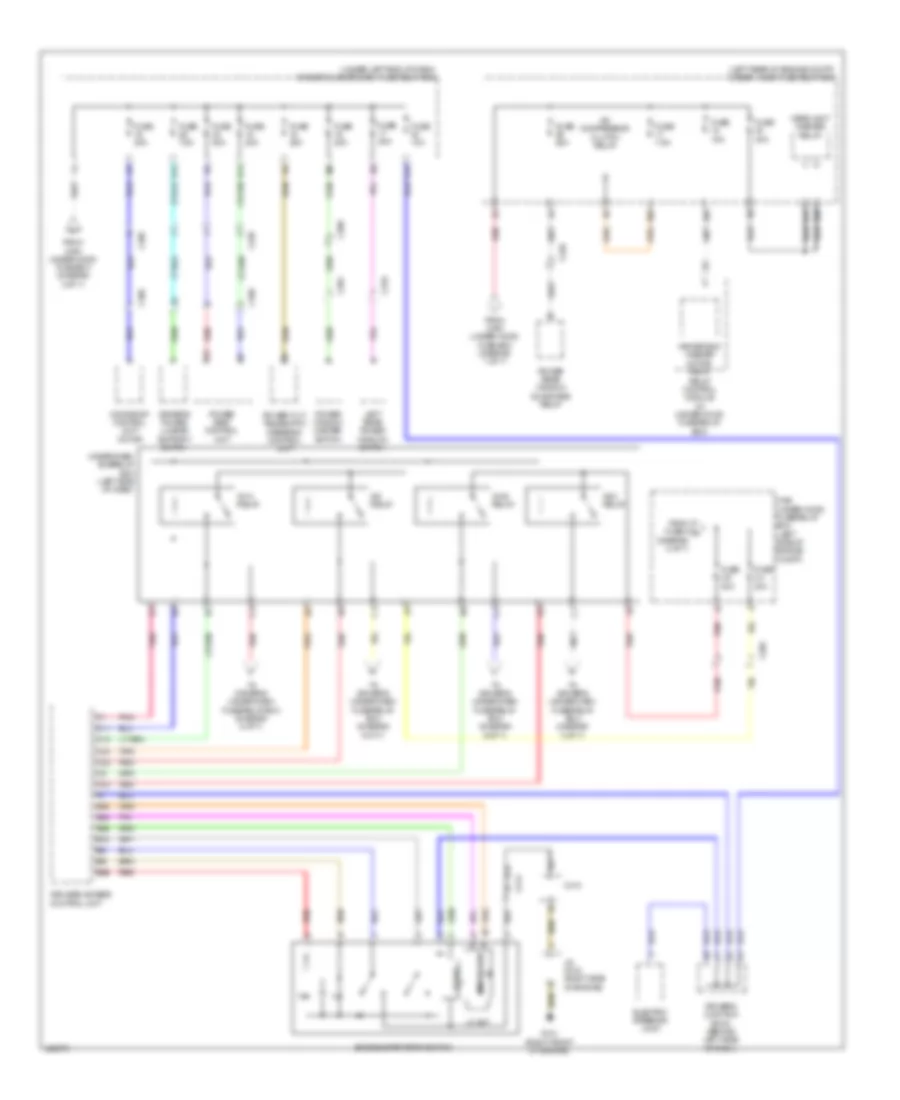
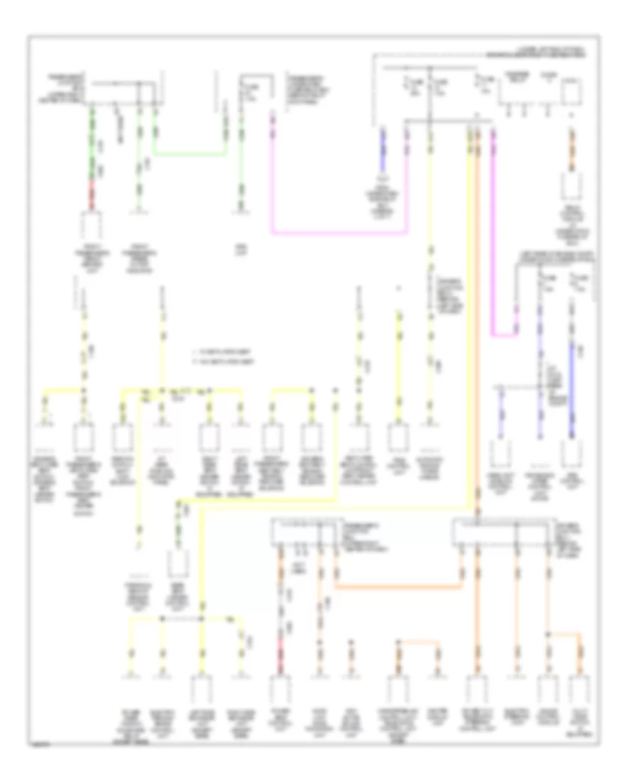
Body Control Modules Wiring Diagram (1 of 2) for Acura RLX 2014
List of elements for Body Control Modules Wiring Diagram (1 of 2) for Acura RLX 2014:
- (left rear corner of engine compt) j/c c018
- Anti-lock brakes & exterior lights systems
- Computer data lines system
- Door locks & anti-theft systems
- Door locks system
- Door locks, instrument cluster, anti-theft & interior lights systems
- Door locks, shift interlock & anti-theft systems
- Driver's under-dash fuse/relay box (under left end of dash)
- E11
- E23
- E25
- E26
- E28
- E43
- E44
- E83
- Engine controls system
- Exterior lights system
- F12
- F17
- F18
- F19
- F20
- F23
- Fuse 10a
- Fuse 7.5a
- G11
- G501 (upper left end of dash)
- G502 (upper left end of dash)
- H12
- Headlights & exterior lights systems
- Headlights system
- Hot at all times
- Hot w/ ig1b relay energized
- Interior lights & trunk, tailgate, fuel doors systems
- Micu
- Navigation & sound systems
- P10
- P11
- P16
- P17
- Pnk
- Power distribution system
- Q10
- Q18
- Q19
- Q20
- Red
- Starting/charging, power windows, engine controls, door locks, anti-theft, transmissions & shift interlock systems
- Trunk, tailgate, fuel doors system
- Under-hood fuse/relay box (left rear of engine compt)
- Wiper/washer system
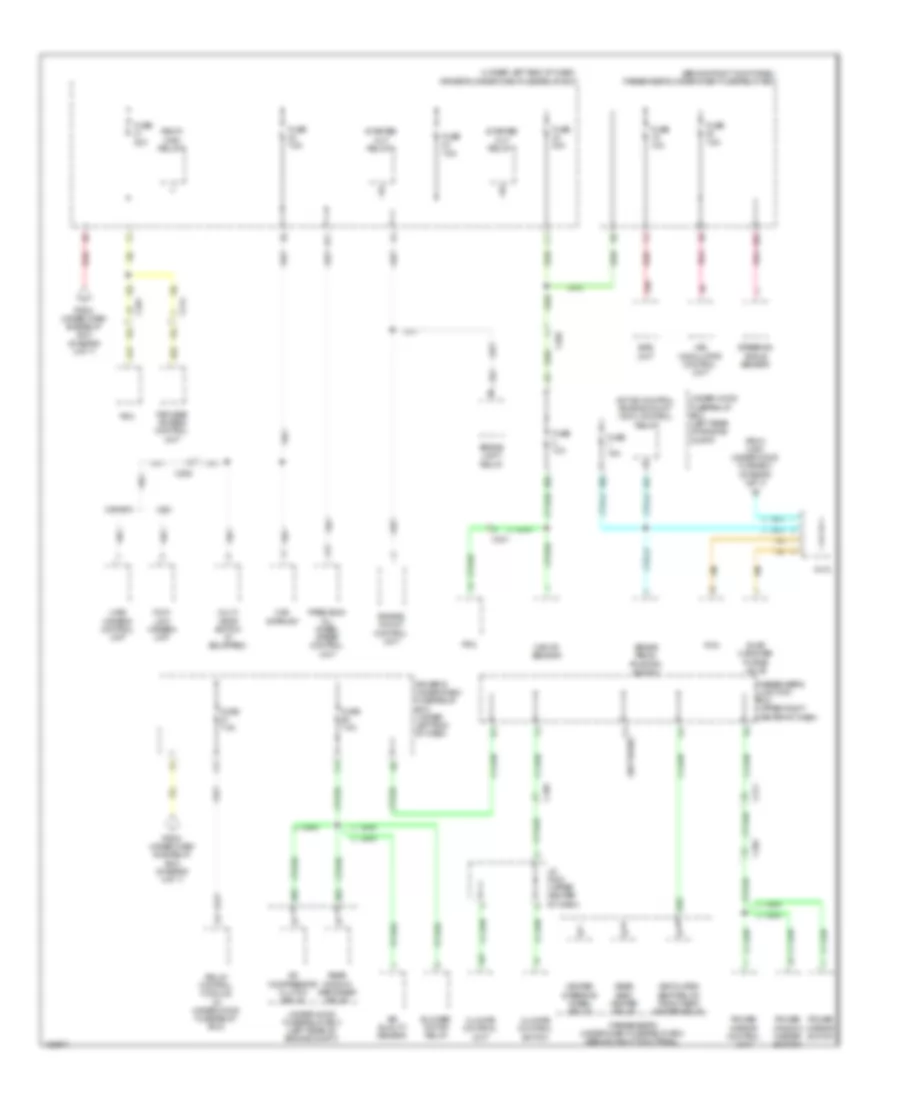
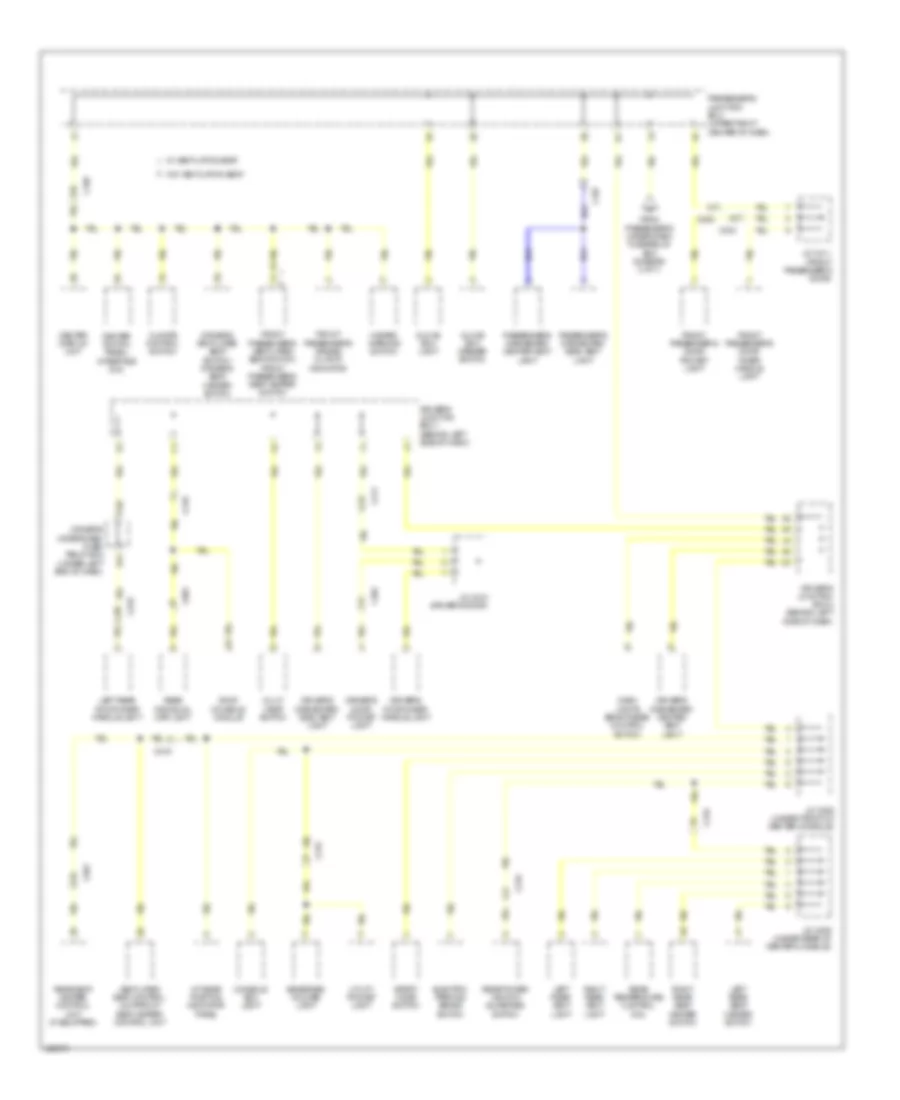
Body Control Modules Wiring Diagram (2 of 2) for Acura RLX 2014
List of elements for Body Control Modules Wiring Diagram (2 of 2) for Acura RLX 2014:
- Computer data lines system
- Door locks & anti-theft systems
- Door locks system
- Driver's under-dash fuse/relay box (under left end of dash)
- E29
- E31
- E42
- Exterior lights system
- F11
- Fuse 15a
- G502 (upper left end of dash)
- Headlights & interior lights systems
- Headlights, exterior lights & interior lights systems
- Hot at all times
- Interior lights system
- Main under-hood fuse box (left side of engine compt)
- Micu
- P13
- P15
- P17
- P19
- P20
- P21
- P22
- P23
- Pnk
- Q11
- Q12
- Q13
- Red
COMPUTER DATA LINES
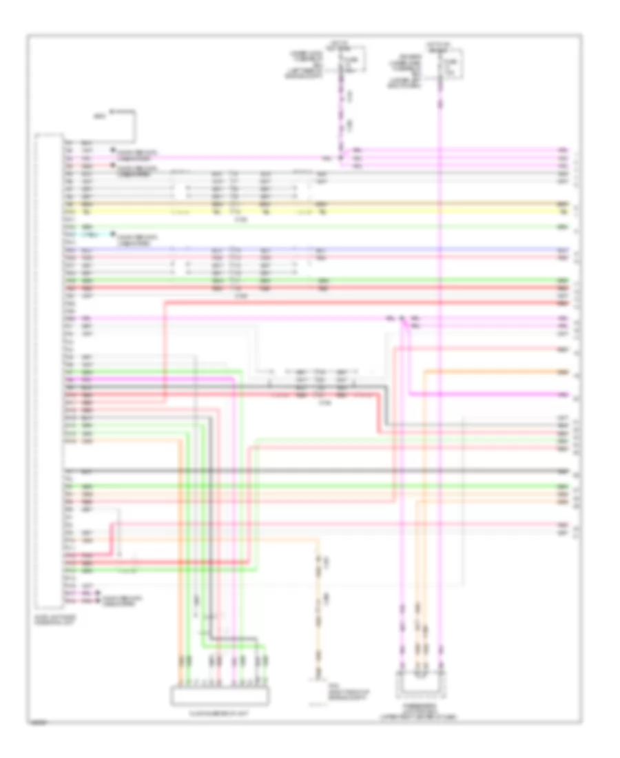
Computer Data Lines Wiring Diagram (1 of 4) for Acura RLX 2014
List of elements for Computer Data Lines Wiring Diagram (1 of 4) for Acura RLX 2014:
- (right end of dash) j/c c001
- (under front of passenger's seat) front passenger's weight sensor unit
- (upper right center of dash) passenger's junction box
- A10
- A11
- A12
- A20
- A21
- A38
- A39
- Anc/ active sound control unit (lower center of dash)
- C101
- C105
- C204
- C206
- C214
- C217
- C219
- C232
- C502
- D10
- Data link connector (dlc) (upper left end of dash)
- Driver's junction box 1 (behind left side of dash)
- Driver's junction box 2 (behind left side of dash)
- Driver's under-dash fuse/relay box (under left end of dash)
- E10
- E83
- Electric parking brake control unit (left front of luggage compt)
- Engine mount control unit (left rear corner of engine compt)
- F10
- F23
- Fuse 10a
- G11
- G503 (lower left center of dash)
- H12
- Hot at all times
- J/c c012 (right rear of engine compt)
- J/c c018 (left rear corner of engine compt)
- J/c c020 (left rear of engine compt)
- K1 pnk
- Micu
- Pcm (right front of engine compt)
- Pnk
- Red
- Srs unit (under front of center console)
- Under-hood fuse/relay box (left rear of engine compt)
- Vsa modulator control unit (right side of engine compt)
Computer Data Lines Wiring Diagram (2 of 4) for Acura RLX 2014
List of elements for Computer Data Lines Wiring Diagram (2 of 4) for Acura RLX 2014:
- (behind left side of dash) driver's junction box 1
- (left center of dash) tpms control unit
- (top of steering column) steering angle sensor
- A14
- C10
- C214
- C218
- C232
- C240
- Can gateway (left center of dash)
- Driver's junction box 2 (behind left side of dash)
- Driver's under-dash fuse/relay box (under left end of dash)
- E40
- Eps control unit (left rear of engine compt)
- F-can connector
- Fuse 7.5a
- G501 (upper left end of dash)
- H10
- Hot w/ ig1a relay energized
- J/c c017 (left rear of engine compt)
- J/c c021 (left rear of engine compt)
- K10
- Passenger's under-dash fuse/relay box (behind right kick panel)
- Pnk
- Precision all wheel steer control unit
- Red
Computer Data Lines Wiring Diagram (3 of 4) for Acura RLX 2014
List of elements for Computer Data Lines Wiring Diagram (3 of 4) for Acura RLX 2014:
- (behind left side of dash) driver's junction box 1
- A25
- A26
- A27
- A28
- Automatic lighting/ rain sensor (except base) (base of interior rearview mirror assembly)
- B20
- B21
- Base
- C205
- C211
- C219
- C301
- Driver's under-dash fuse/relay box (under left end of dash)
- Except base
- Fcw/ldw camera unit
- Gauge control module
- J/c c024 (in roof console)
- Keyless access control unit (left end of dash)
- Micu
- Pnk
- Power window master switch
- Red
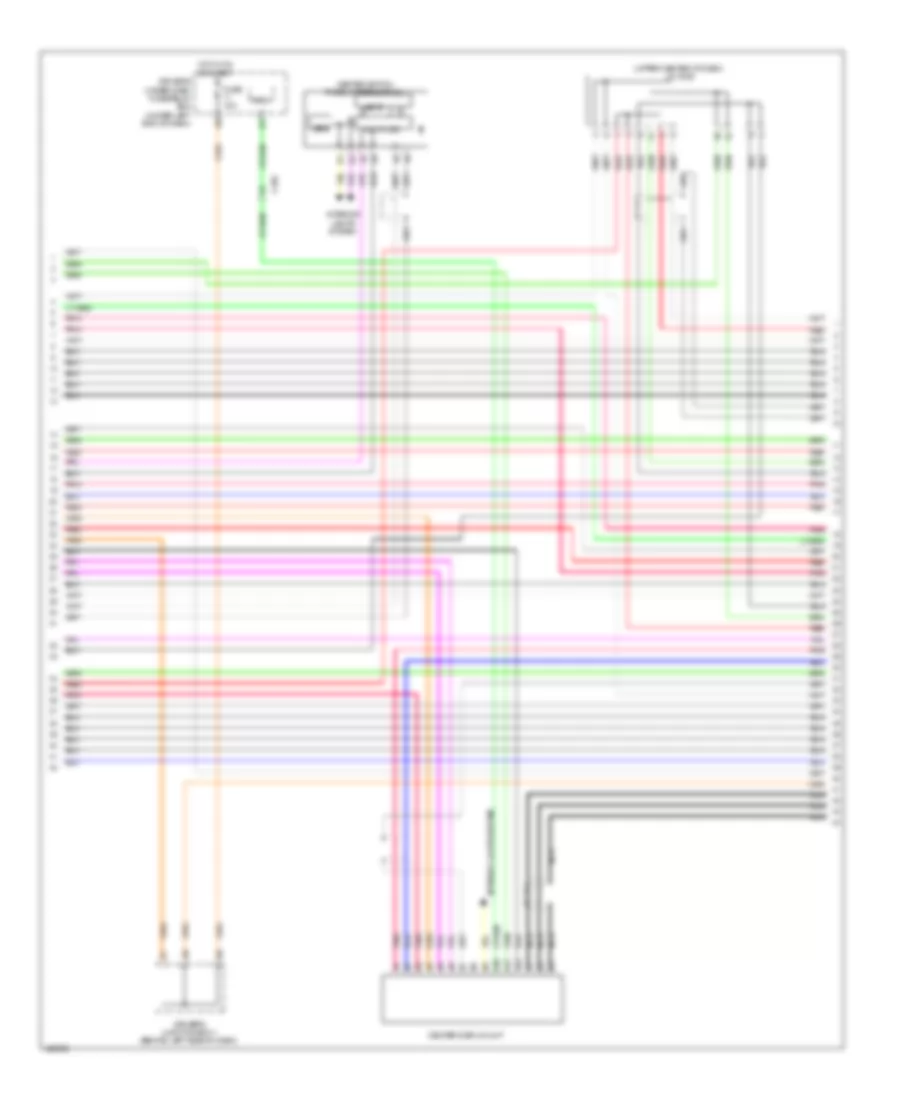
Computer Data Lines Wiring Diagram (4 of 4) for Acura RLX 2014
List of elements for Computer Data Lines Wiring Diagram (4 of 4) for Acura RLX 2014:
- (in under-hood fuse/relay box) relay control module
- (left "c" pillar) j/c c008
- (left rear of engine compt) headlight leveling control unit
- (left rear of engine compt) j/c c019
- (under left side of cowl cover) windshield wiper control unit/motor
- A13
- A33
- A34
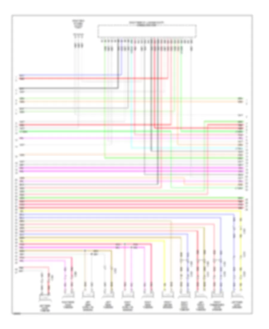
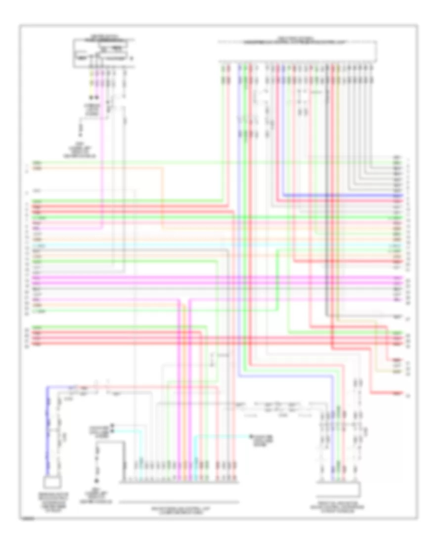
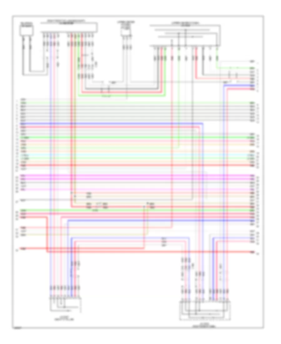
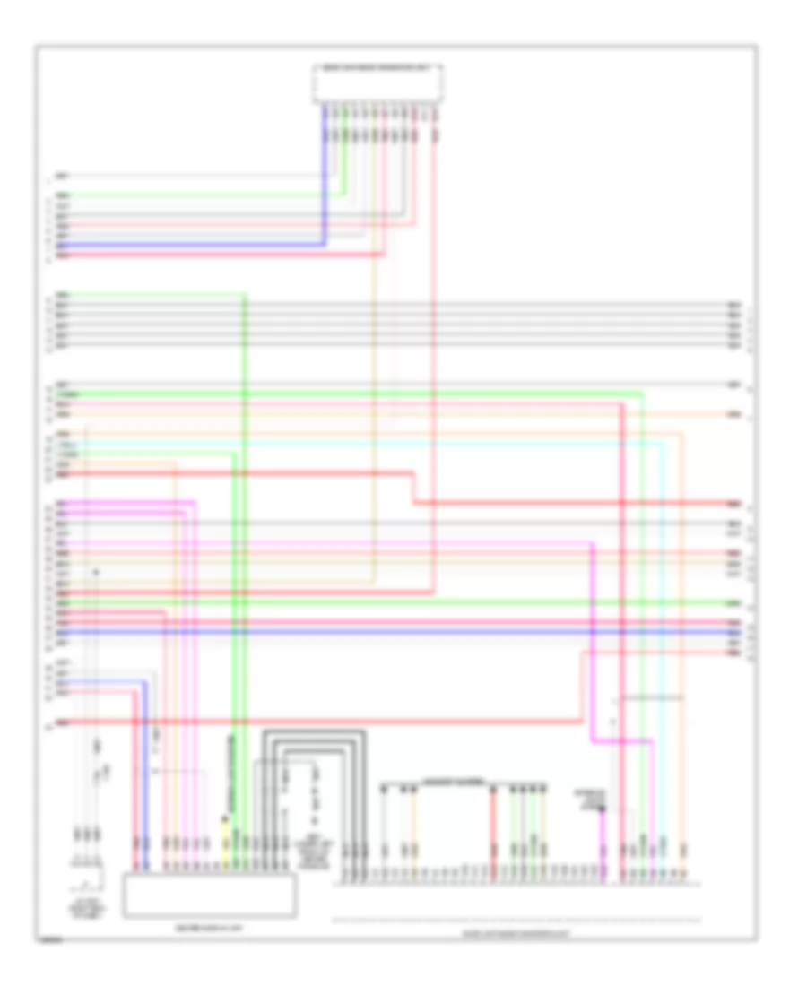
- Audio unit/audio navigation unit (if equipped)
- B15
- B16
- B17
- C102
- C103
- C104
- C214
- C218
- C224
- C232
- C503
- Climate control unit (behind right center of dash)
- F17
- F18
- Handsfreelink control unit/ telematics control unit (if equipped) (right end of dash)
- J/c c003 (upper center of dash)
- J/c c004 (right side of dash)
- J/c c006 (right "c" pillar)
- J/c c023 (under center console)
- Left side bsi radar unit (if equipped) (left rear side of luggage compt)
- Pnk
- Power seat control unit
- Red
- Right side bsi radar unit (if equipped) (right rear side of luggage compt)
COOLING FAN
Cooling Fan Wiring Diagram for Acura RLX 2014
List of elements for Cooling Fan Wiring Diagram for Acura RLX 2014:
- (behind left side of radiator) radiator fan motor
- A/c condenser fan motor (right front of engine compt)
- A10
- A14
- A20
- A31
- B45
- C401
- C48
- Computer data lines system
- E20
- E21
- E49
- E50
- E75
- E95
- E96
- Ect sensor 1 (top left rear of engine)
- Ect sensor 2 (on lower radiator outlet)
- Engine controls system
- Fuse 15a
- Fuse 2-2 60a
- Fuse 2-4 50a
- Fuse 7.5a
- G302 (left front of engine compt)
- Hot at all times
- J/c c016 (right rear of engine)
- J/c c018 (left rear corner of engine compt)
- Main under-hood fuse box (left side of engine compt)
- Pcm (right front of engine compt)
- Pgm-fi sub relay
- Pnk
- Radiator fan relay (left side of engine compt)
- Red
- Rfc unit (rear of a/c condenser fan motor assembly)
- Under-hood fuse/relay box (left rear of engine compt)
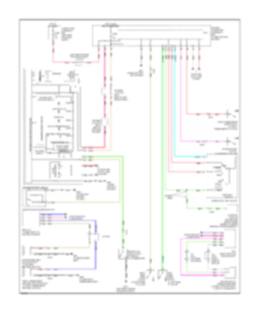
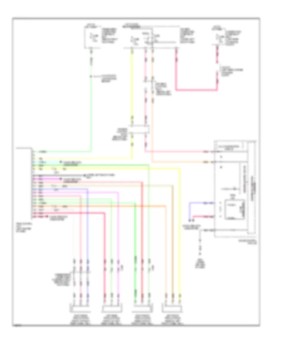
CRUISE CONTROL
Cruise Control Wiring Diagram (1 of 2) for Acura RLX 2014
List of elements for Cruise Control Wiring Diagram (1 of 2) for Acura RLX 2014:
- (right front of engine) g101
- A/t gear position indicator panel
- A10
- A13
- A24
- A25
- A41
- A42
- A43
- A44
- A45
- A46
- App sensor (left rear of engine compt)
- App sensor a
- App sensor b
- B10
- B11
- B23
- B29
- B31
- B40
- B43
- B44
- B45
- B46
- B48
- Brake pedal position switch (on brake pedal mounting bracket)
- C21
- C214
- C32
- C33
- C401
- C406
- C410
- Computer data lines system
- E12
- E13
- E22
- E23
- E41
- E42
- E51
- E52
- E68
- E76
- E77
- E83
- E86
- Engine controls system
- Etcs control relay
- Fuse 10a
- Fuse 15a
- Fuse 7.5a
- G503 (lower left center of dash)
- Hot at all times
- Hot in on or start
- Input shaft (mainshaft) speed sensor (in transmission housing)
- J/c c014 (top rear of engine)
- J/c c015 (right side of engine)
- J/c c016 (right rear of engine)
- N d
- Pcm (right front of engine compt)
- Pgm-fi main relay 1
- Pnk
- Red
- Tan
- Throttle actuator
- Throttle body (top rear of engine)
- Throttle open sensor
- Transmission range switch (on transaxle)
- Under-hood fuse/relay box (left rear of engine compt)
Cruise Control Wiring Diagram (2 of 2) for Acura RLX 2014
List of elements for Cruise Control Wiring Diagram (2 of 2) for Acura RLX 2014:
- (upper left end of dash) g501
- +5v
- 3.3v
- 32bit micro computer + flash rom
- A27
- A28
- A30
- A32
- Amp
- C11
- C16
- C17
- C214
- Cable reel (in steering column)
- Cancel switch
- Circuit 5v control
- Computer data lines system
- Cruise control combination switch
- Cruise control ind
- Cruise light dimming circuit
- Cruise main ind
- Disp switch
- Driver's junction box 1 (behind left side of dash)
- Driver's junction box 2 (behind left side of dash)
- Driver's under-dash fuse/relay box (under left end of dash)
- Exterior lights system
- F-canh
- F-canl
- F23
- Flash 8mb/32mb
- Fuse 10a
- G501 (upper left end of dash)
- Gauge control module
- Hot in on or start
- J/c c014 (top rear of engine)
- J/c c018 (left rear corner of engine compt)
- Keyless access control unit (left end of dash)
- Main switch
- Micu
- Multi-information display (tft)
- Output shaft (countershaft) speed sensor (on transmission housing)
- Pnk
- Push switch
- Red
- Res/+ switch
- Rjog
- Set/- switch
- Sig gnd
- Speaker
- Steering commander switch assembly
- Tan
- Transceiver f-can
- Transmissions system
- Warning driver circuit
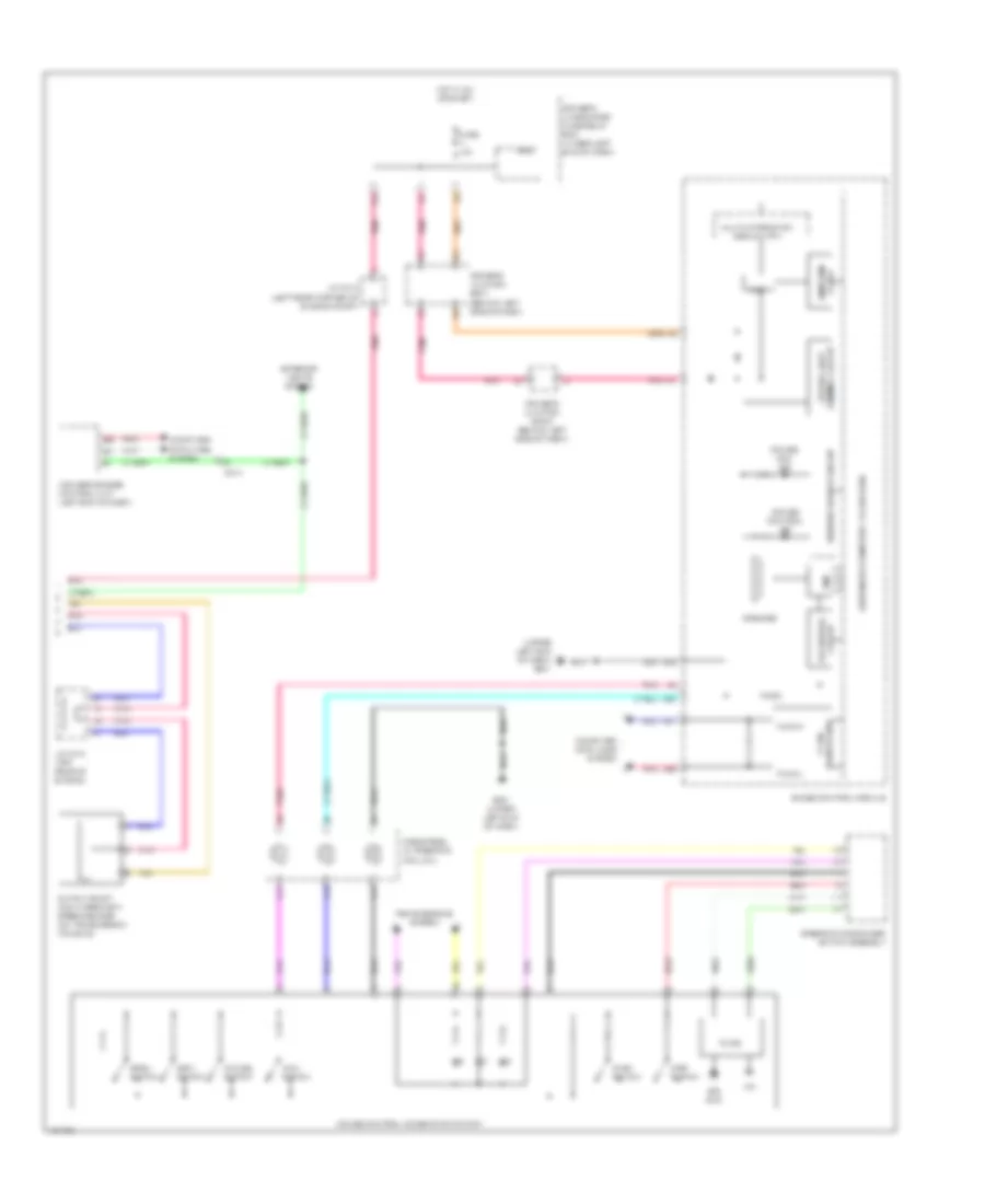
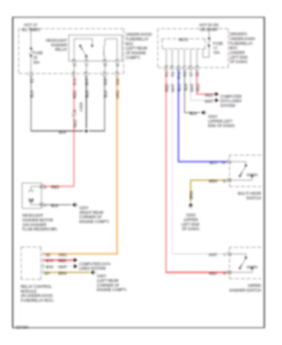
DEFOGGERS
Defoggers Wiring Diagram for Acura RLX 2014
List of elements for Defoggers Wiring Diagram for Acura RLX 2014:
- (upper left end of dash) g502
- A15
- A19
- A22
- A28
- B11
- B15
- B16
- C105
- C208
- C210
- C211
- C226
- C301
- C303
- Center of dash)
- Climate control switch
- Climate control unit (behind right
- Computer data lines system
- Control block
- Driver's under-dash fuse/relay box (under left end of dash)
- E33
- E34
- Front passenger's power window switch
- Fuse 20a
- Fuse 3-8 40a
- Fuse 7.5a
- G502 (upper left end of dash)
- G505 (right end of dash)
- G601 (under left front of center console)
- G703 (under center of rear shelf)
- G704 (left "c" pillar)
- G752 (under center of rear shelf)
- Hot at all times
- Hot w/ ig2 relay energized
- J/c c003 (upper center of dash)
- J/c c010 (driver's door)
- J/c c011 (front passenger's door)
- Left power mirror
- Main under-hood fuse box (left side of engine compt)
- Noise reduction condenser a (under left side of rear shelf)
- Noise reduction condenser b (under left side of rear shelf)
- Passenger's junction box (upper right center of dash)
- Passenger's under-dash fuse/relay box (behind right kick panel)
- Pnk
- Power mirror control unit (in driver's door)
- Power mirror defogger
- Power window master switch
- Rear window defogger
- Rear window defogger relay
- Rear window defogger switch/ power mirror defogger switch
- Rear window defogger switch/ power mirror defogger switch indicator (led)
- Red
- Relay control module (in under-hood fuse/relay box)
- Right power mirror
- Under-hood fuse/relay box (left rear of engine compt)
ELECTRONIC POWER STEERING
Active 4 Wheel Power Steering Wiring Diagram for Acura RLX 2014
List of elements for Active 4 Wheel Power Steering Wiring Diagram for Acura RLX 2014:
- (behind left side of dash) driver's junction box 1
- (left rear of luggage compt) g705
- 32bit microcomputer + flash rom
- A10
- A11
- A12
- A13
- A14
- A15
- A27
- A28
- A32
- C226
- C228
- C230
- C234
- C235
- Computer data lines system
- Driver circuit warning
- Driver's junction box 2 (behind left side of dash)
- Driver's under-dash fuse/relay box (under left end of dash)
- E17
- E83
- F-can h
- F-can l
- F23
- Fuse 10a
- Fuse 3-7 40a
- Fuse 40a
- Fuse 7.5a
- G501 (upper left end of dash)
- G705 (left rear of luggage compt)
- Gauge control module
- Hot at all times
- Hot in on or start
- J/c c018 (left rear corner of engine compt)
- Left rear precision all wheel steer actuator (in left rear wheelwell)
- Main under-hood fuse box (left side of engine compt)
- Micu
- Motor
- Pnk
- Precision all wheel steer control unit
- Rear toe control ind
- Red
- Right rear precision all wheel steer actuator (in right rear wheelwell)
- Sensor position
- Transceiver f-can
Electronic Power Steering Wiring Diagram for Acura RLX 2014
List of elements for Electronic Power Steering Wiring Diagram for Acura RLX 2014:
- 32bit microcomputer + flash rom
- A27
- A28
- A32
- Battery terminal fuse box (on battery positive (+) post)
- C240
- Compulsory turning-on circuit
- Computer data lines system
- Driver circuit warning
- Driver's junction box 1 (behind left side of dash)
- Driver's junction box 2 (behind left side of dash)
- Driver's under-dash fuse/relay box (under left end of dash)
- E26
- E73
- E83
- Eps control unit (left rear of engine compt)
- Eps ind
- F-can h
- F-can l
- F23
- Fail-safe circuit
- Fuse 10a
- Fuse 7.5a
- Fuse 80a
- G501 (upper left end of dash)
- Gauge control module
- Hot at all times
- Hot in on or start
- J/c c018 (left rear corner of engine compt)
- Micu
- Passenger's under-dash fuse/relay box (behind right kick panel)
- Pnk
- Red
- Steering angle sensor (top of steering column)
- Transceiver f-can
- Under-hood fuse/relay box (left rear of engine compt)
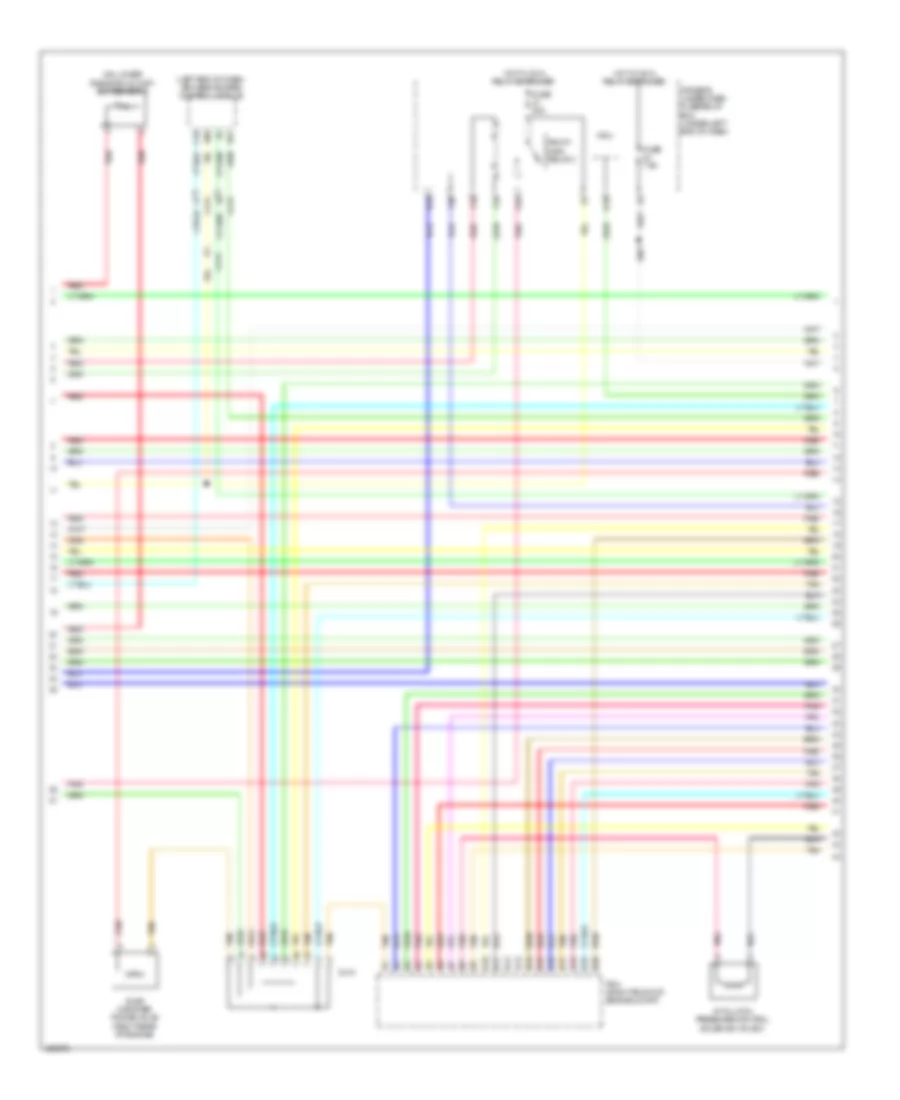
ENGINE PERFORMANCE
3.5L
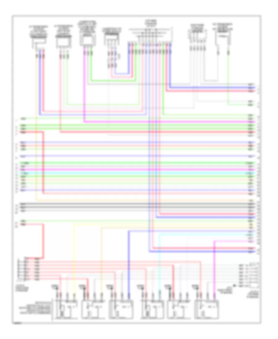
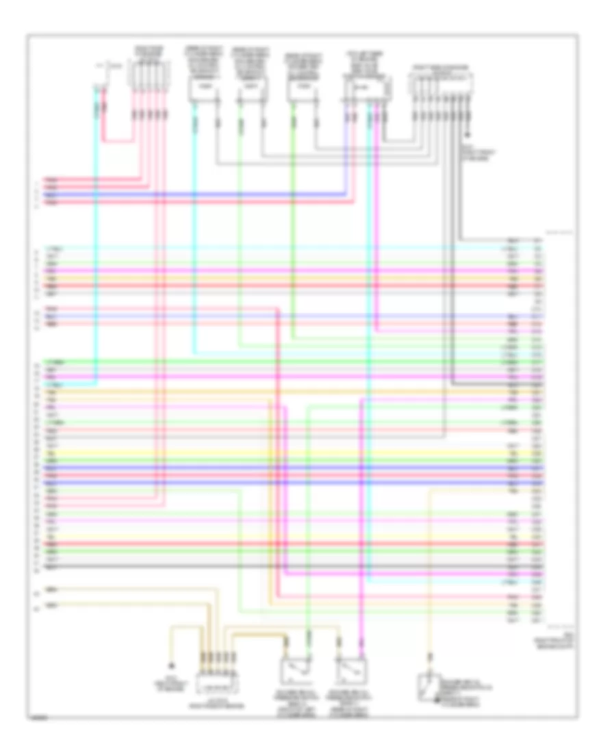
3.5L, Engine Performance Wiring Diagram (1 of 10) for Acura RLX 2014
List of elements for 3.5L, Engine Performance Wiring Diagram (1 of 10) for Acura RLX 2014:
- (behind center of fuel tank) ftp sensor
- (left rear corner of engine compt) j/c c018
- A10
- A11
- A12
- A13
- A14
- A15
- A16
- A17
- A18
- A19
- A20
- A21
- A22
- A23
- A24
- A25
- A26
- A27
- A28
- A29
- A30
- A31
- A32
- A33
- A34
- A35
- A36
- A37
- A38
- A39
- A40
- A41
- A42
- A43
- A44
- A45
- A46
- A47
- A48
- A49
- A50
- A51
- Air conditioning system
- App sensor (left rear of engine compt)
- Audio unit/ audio-navigation unit
- C101
- C203
- C204
- C206
- C213
- C220
- C401
- C406
- Computer data lines system
- E12
- E13
- E22
- E23
- E41
- E42
- E51
- E52
- E76
- E77
- Etcs control relay
- F10
- Fuel pump control module (left front of luggage compt)
- Fuel tank unit (top of fuel tank)
- Fuse 15a
- G702 (under center of rear shelf)
- Hot at all times
- Instrument cluster system
- Maf/iat sensor (on intake air duct)
- Park pin switch/shift lock solenoid (base of shift lever assembly)
- Passenger's junction box (upper right center of dash)
- Pcm (right front of engine compt)
- Pgm-fi main relay 1
- Pnk
- Red
- Starting/ charging system
- Starting/charging system
- Under-hood fuse/relay box (left rear of engine compt)
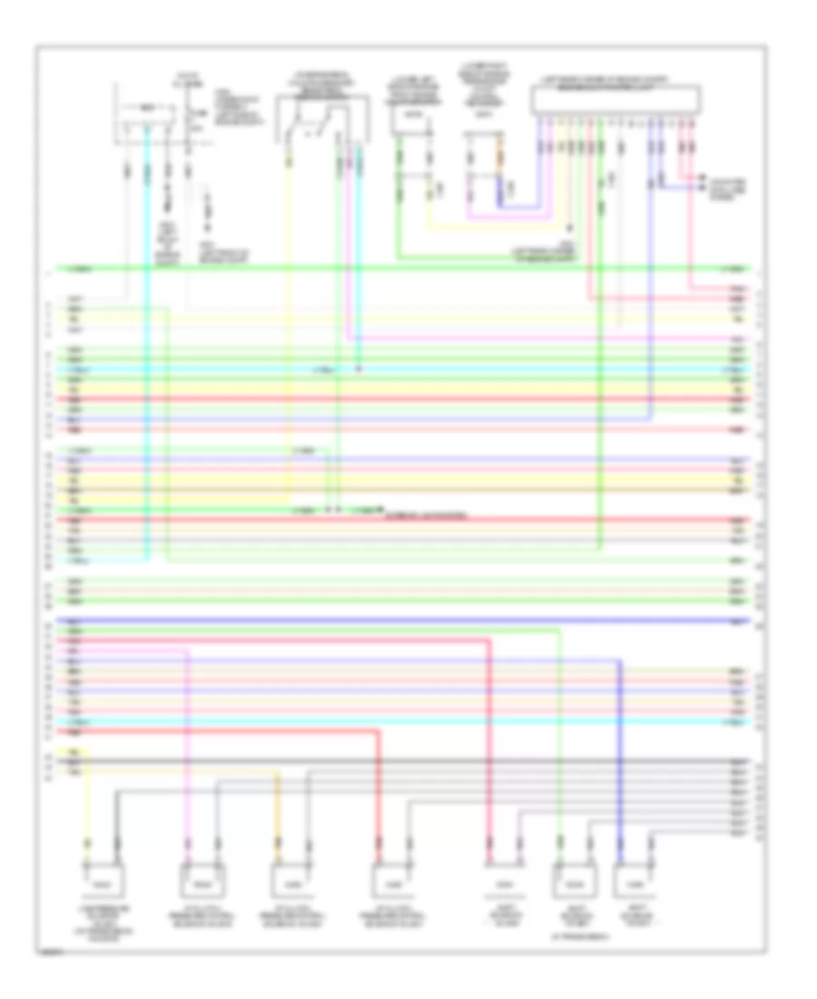
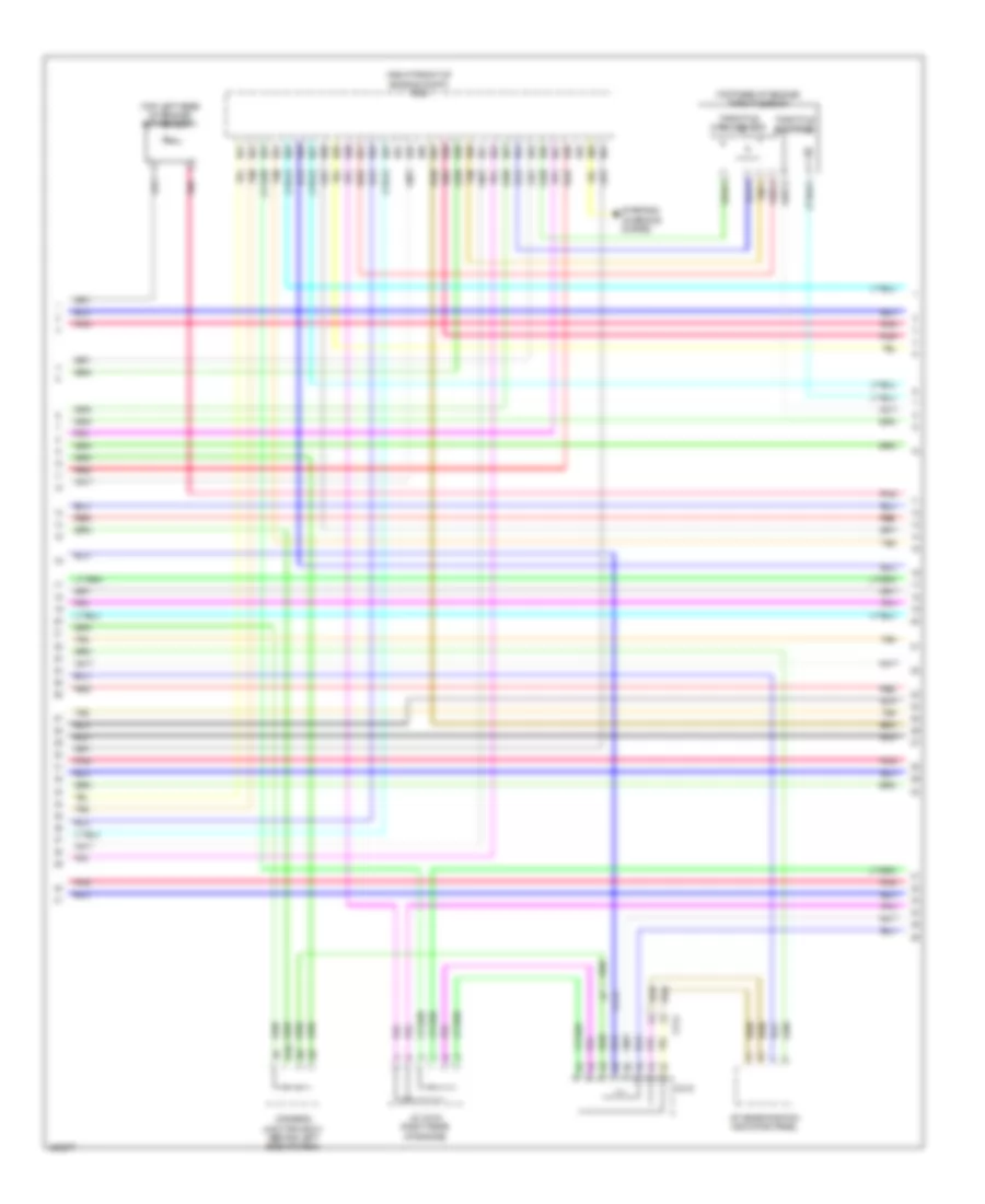
3.5L, Engine Performance Wiring Diagram (2 of 10) for Acura RLX 2014
List of elements for 3.5L, Engine Performance Wiring Diagram (2 of 10) for Acura RLX 2014:
- (left end of dash) keyless access control module
- (on lower radiator outlet) ect sensor 2
- A/t clutch pressure control solenoid valve c
- B10
- B11
- B12
- B13
- B14
- B15
- B16
- B17
- B18
- B19
- B20
- B28
- C18
- C214
- C410
- Driver's under-dash fuse/relay box (under left end of dash)
- E16
- Evap canister purge valve (right rear of engine)
- F10
- F16
- F30
- Fuse 20a
- Fuse 7.5a
- H10
- Hot w/ ig1a relay energized
- Micu
- Pcm (right front of engine compt)
- Pgm-fi main relay 2
- Pnk
- Q18
- Red
- Tan
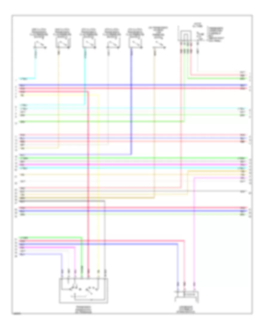
3.5L, Engine Performance Wiring Diagram (3 of 10) for Acura RLX 2014
List of elements for 3.5L, Engine Performance Wiring Diagram (3 of 10) for Acura RLX 2014:
- (in transmission)
- (left rear corner of engine compat) engine mount control unit
- (lower left side of engine) front engine mount actuator
- (lower right side of engine) rear engine mount control actuator
- (on brake pedal mounting bracket) brake pedal position switch
- A/t clutch pressure control solenoid valve a
- A/t clutch pressure control solenoid valve b
- A/t clutch pressure control solenoid valve d
- C240
- C401
- C407
- Computer data lines system
- Eld
- Exterior lights system
- Fuse 20a
- G301 (left front of engine compt)
- G401 (left rear corner of engine compt)
- Hot at all times
- Line pressure solenoid valve a (on transmission housing)
- Main under-hood fuse box (left side of engine compt)
- Pnk
- Red
- Shift solenoid valve a
- Shift solenoid valve b
- Shift solenoid valve c
- Tan
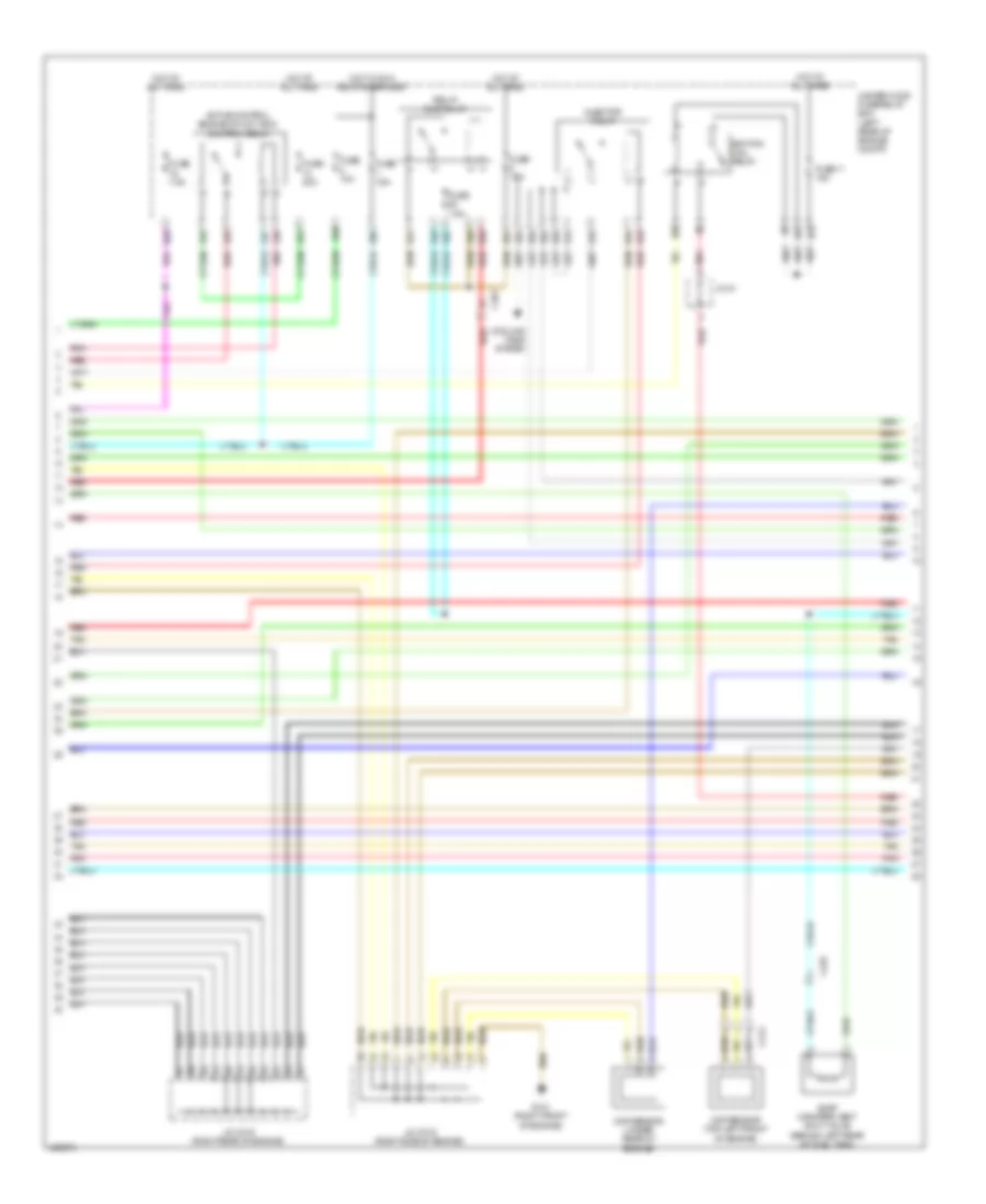
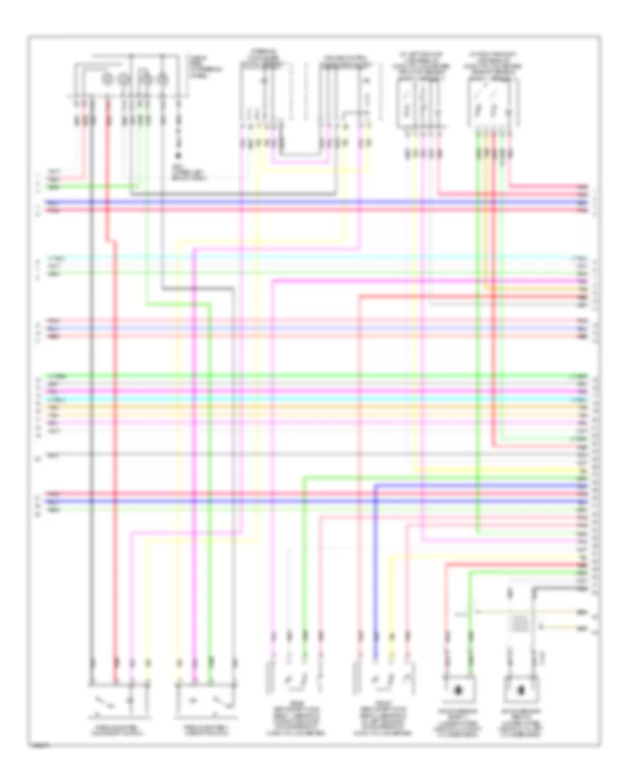
3.5L, Engine Performance Wiring Diagram (4 of 10) for Acura RLX 2014
List of elements for 3.5L, Engine Performance Wiring Diagram (4 of 10) for Acura RLX 2014:
- Active control engine mount (acm) control relay
- C232
- C401
- C410
- C413
- Ckp sensor (under rear of engine)
- Cmp sensor (top left front of engine)
- Cooling fans system
- E14
- E15
- E18
- E19
- E20
- E21
- E37
- E38
- E43
- E44
- E47
- E48
- E49
- E50
- E62
- E63
- E64
- E68
- E69
- E75
- E78
- E79
- E86
- E95
- E96
- Evap canister vent shut valve (behind left rear of fuel tank)
- Fuse 10a
- Fuse 11 15a
- Fuse 15a
- Fuse 20a
- Fuse 7.5a
- G101 (right front of engine)
- Hot at all times
- Hot w/ ig1a relay energized
- Ignition coil relay
- Injector relay
- J/c c015 (right side of engine)
- J/c c016 (right rear of engine)
- Pgm-fi sub relay
- Pnk
- Red
- Tan
- Under-hood fuse/relay box (left rear of engine compt)
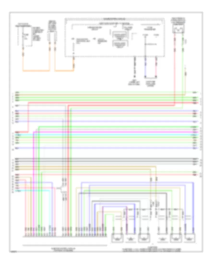
3.5L, Engine Performance Wiring Diagram (5 of 10) for Acura RLX 2014
List of elements for 3.5L, Engine Performance Wiring Diagram (5 of 10) for Acura RLX 2014:
- (behind left side of dash) driver's junction box 1
- (right rear of intake manifold) high pressure fuel pump
- 32bit microcomputer + flash rom
- A16
- A27
- A28
- C10
- C11
- C12
- C408
- C410
- C411
- Compulsory turning off circuit
- Compulsory turning on circuit
- Computer data lines system
- Driver's under-dash fuse/relay box (under left end of dash)
- F-can h
- F-can l
- F-can transceiver
- Fall safe circuit
- Fuse 10a
- G501 (upper left end of dash)
- Gauge control module
- Hot w/ ig1 b relay energized
- Injector control module (top front of engine)
- Injectors (injectors 1, 2 & 3: under intake manifold in right bank cylinder) (injectors 4, 5 & 6: under intake manifold in left bank cylinder)
- Low oil pressure ind
- Malfunction indicator lamp (mil)
- Pnk
- Red
- Tan
- Warning driver circuit
3.5L, Engine Performance Wiring Diagram (6 of 10) for Acura RLX 2014
List of elements for 3.5L, Engine Performance Wiring Diagram (6 of 10) for Acura RLX 2014:
- (in transmission housing) input shaft (mainshaft) speed sensor
- (in transmission housing) output shaft (countershaft) speed sensor
- (on transmission housing) atf temperature sensor
- (right rear of engine) j/c c016
- (top rear of engine) j/c c014
- (under front of intake manifold) frp sensor
- (under intake manifold, in left cylinder bank) rocker arm oil pressure sensor
- C413
- G101 (right front of engine)
- Icm
- Ignition coils (ignition coils 1, 2 & 3: top of right cylinder bank) (ignition coils 4, 5 & 6: top of left cylinder bank)
- J/c c013 (right side of engine)
- J/c c014 (top rear of engine)
- Nca
- Pnk
- Red
- Spark plug
- Tan
3.5L, Engine Performance Wiring Diagram (7 of 10) for Acura RLX 2014
List of elements for 3.5L, Engine Performance Wiring Diagram (7 of 10) for Acura RLX 2014:
- (right front of engine compt) pcm
- (top left rear of engine) ect sensor 1
- (top rear of engine) throttle body
- A/t gear position indicator panel
- B21
- B22
- B23
- B24
- B25
- B26
- B27
- B28
- B29
- B30
- B31
- B32
- B33
- B34
- B35
- B36
- B37
- B38
- B39
- B40
- B41
- B42
- B43
- B44
- B45
- B46
- B47
- B48
- B49
- B50
- B51
- C214
- C410
- D10
- Driver's junction box 1 (behind left side of dash)
- J/c c016 (right rear of engine)
- Pnk
- Red
- Starting/ charging system
- Tan
- Throttle actuator
- Throttle open sensor
3.5L, Engine Performance Wiring Diagram (8 of 10) for Acura RLX 2014
List of elements for 3.5L, Engine Performance Wiring Diagram (8 of 10) for Acura RLX 2014:
- (2nd clutch) transmission fluid pressure switch a
- (3rd clutch) transmission fluid pressure switch b
- (4th clutch) transmission fluid pressure switch c
- (5th clutch) transmission fluid pressure switch d
- (6th clutch) transmission fluid pressure switch e
- (on transmission housing) line pressure switch
- E31
- E33
- Fuse 7.5a
- Hot at all times
- Map sensor (top rear of intake manifold)
- Passenger's under-dash fuse/relay box (behind right kick panel)
- Pnk
- Red
- Tan
- Transmission range switch (on transaxle)
3.5L, Engine Performance Wiring Diagram (9 of 10) for Acura RLX 2014
List of elements for 3.5L, Engine Performance Wiring Diagram (9 of 10) for Acura RLX 2014:
- (in left exhaust, upstream of catalytic converter) front a/f sensor (bank 2, sensor 1)
- (in right exhaust, upstream of catalytic converter) rear a/f sensor (bank 1, sesnor 1)
- C11
- C12
- C13
- C14
- C15
- C18
- C412
- Cable reel (in steering wheel)
- Cruise control combination switch
- Front secondary ho2s (bank 2, sensor 2) (in left exhaust, downstream of catalytic converter)
- G501 (upper left end of dash)
- Knock sensor (bank 1) (under intake manifold, in right cylinder bank)
- Knock sensor (bank 2) (under intake manifold, in left cylinder bank)
- Paddle shifter + (upshift switch)
- Paddle shifter - (downshift switch)
- Pnk
- Rear secondary ho2s (bank 1, sensor 2) (in right exhaust, downstream of catalytic converter)
- Red
- Steering commander switch assembly
- Tan
3.5L, Engine Performance Wiring Diagram (10 of 10) for Acura RLX 2014
List of elements for 3.5L, Engine Performance Wiring Diagram (10 of 10) for Acura RLX 2014:
- (rear of right cylinder bank) rocker arm oil control solenoid a (bank 1)
- (rear of right cylinder bank) rocker arm oil control solenoid a (bank 2)
- (rear of right cylinder bank) rocker arm oil control solenoid b
- (right side of engine) j/c c013
- (right side of engine) j/c c015
- (top left rear of engine) egr valve/ egr valve position sensor
- C10
- C11
- C12
- C13
- C14
- C15
- C16
- C17
- C18
- C19
- C20
- C21
- C22
- C23
- C24
- C25
- C26
- C27
- C28
- C29
- C30
- C31
- C32
- C33
- C34
- C35
- C36
- C37
- C38
- C39
- C40
- C41
- C410
- C42
- C43
- C44
- C45
- C46
- C47
- C48
- C49
- C50
- C51
- G101 (right front of engine)
- J/c c015 (right side of engine)
- Pcm (right front of engine compt)
- Pnk
- Red
- Rocker arm oil pressure switch (bank 1) (rear of right cylinder bank)
- Rocker arm oil pressure switch (bank 2) (front of left cylinder bank)
- Rocker arm oil pressure switch b (bank 1) (rear of right cylinder bank)
- Tan
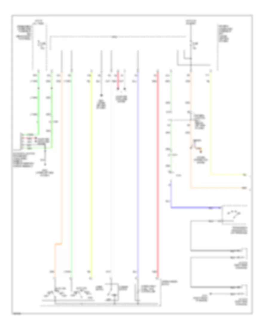
EXTERIOR LIGHTS
Backup Lamps Wiring Diagram for Acura RLX 2014
List of elements for Backup Lamps Wiring Diagram for Acura RLX 2014:
- A10
- A16
- Audio unit/ audio navigation unit
- Automatic dimming inside mirror
- C103
- C218
- C227
- C410
- Computer data lines system
- Diode a
- Diode b
- Driver's junction box 1 (behind left side of dash)
- Driver's under-dash fuse/ relay box (under left end of dash)
- E42
- F30
- Fuse 10a
- G101 (right front of engine)
- G24
- G705 (left rear of luggage compt)
- H10
- Hot w/ ig1b relay energized
- J/c c015 (right side of engine)
- J/c c016 (right rear of engine)
- Left backup light
- Micu
- Passenger's junction box (upper right center of dash)
- Pcm (right front of engine compt)
- Pnk
- Red
- Reverse relay
- Right backup light
- Transmission range switch (on transaxle)
Exterior Lamps Wiring Diagram (1 of 3) for Acura RLX 2014
List of elements for Exterior Lamps Wiring Diagram (1 of 3) for Acura RLX 2014:
- A11
- A12
- A25
- Brake light relay
- Brake pedal position switch (on brake pedal mounting bracket)
- C214
- C232
- C404
- C406
- Computer data lines system
- E24
- E25
- E26
- E31
- E32
- E53
- E54
- E59
- E60
- E65
- E66
- E67
- E83
- E86
- E89
- Fuse 10a
- Fuse 15a
- Fuse 7.5a
- G202 (right rear corner of engine compt)
- G706 (left rear of luggage compt)
- Hot at all times
- J/c c018 (left rear corner of engine compt)
- Keyless access control unit (left end of dash)
- Left brake light/ taillight/ rear side marker light
- Pcm (right front of engine compt)
- Pnk
- Red
- Right brake light/ taillight/ rear side marker light
- Taillight relay
- Under-hood fuse/relay box (left rear of engine compt)
- Vsa modulator control unit (right side of engine compt)
Exterior Lamps Wiring Diagram (2 of 3) for Acura RLX 2014
List of elements for Exterior Lamps Wiring Diagram (2 of 3) for Acura RLX 2014:
- B13
- C101
- C105
- C227
- Computer data lines system
- Driver's under-dash fuse/relay box (under left end of dash)
- E11
- F11
- F12
- F23
- Fuse 10a
- Fuse 15a
- Fuse 7.5a
- G501 (upper left end of dash)
- G705 (left rear of luggage compt)
- G706 (left rear of luggage compt)
- Hazard warning switch
- Hazard warning switch light
- High mount brake light
- Hot at all times
- Hot w/ ig1a relay energized
- Hot w/ ig1b relay energized
- Interior lights system
- Left inner taillight
- Left license plate light
- Left rear turn signal light
- Main under-hood fuse box (left side of engine compt)
- Micu
- P13
- P15
- P17
- P19
- P22
- P23
- Pnk
- Q11
- Red
- Relay control module (in under-hood fuse/relay box)
- Right inner taillight
- Right license plate light
- Right rear turn signal light
Exterior Lamps Wiring Diagram (3 of 3) for Acura RLX 2014
List of elements for Exterior Lamps Wiring Diagram (3 of 3) for Acura RLX 2014:
- 32bit microcomputer + flash rom
- A17
- A18
- A27
- A28
- A32
- Auto
- Automatic lighting/ rain sensor (base of interior rearview mirror assembly)
- C205
- C208
- C209
- C210
- C404
- Combination light switch
- Computer data lines system
- D32
- Driver junction box 1 (behind left side of dash)
- Driver junction box 2 (behind left side of dash)
- E42
- Except base
- F can transceiver
- F-can h
- F-can l
- Fuse 7.5a
- G201 (right rear corner of engine compt)
- G301 (left front of engine compt)
- G501 (upper left end of dash)
- G502 (upper left end of dash)
- G505 (right end of dash)
- Gauge control module
- Head
- Headlight switch
- Interior lights system
- J/c c010 (driver's door)
- J/c c011 (front passenger's door)
- Left
- Left front side marker light
- Left front turn signal/ parking light
- Left led control unit assembly (low beam) (rear of left headlight assembly)
- Left power mirror
- Left turn signal ind
- Off
- Park
- Passenger's under-dash fuse/relay box (behind right kick panel)
- Pnk
- Red
- Right
- Right front side marker light
- Right front turn signal/ parking light
- Right led control unit assembly (low beam) (rear of right headlight assembly)
- Right power mirror
- Right turn signal ind
- Turn signal switch
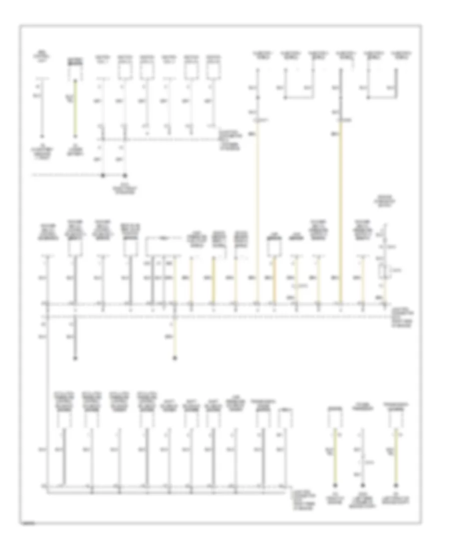
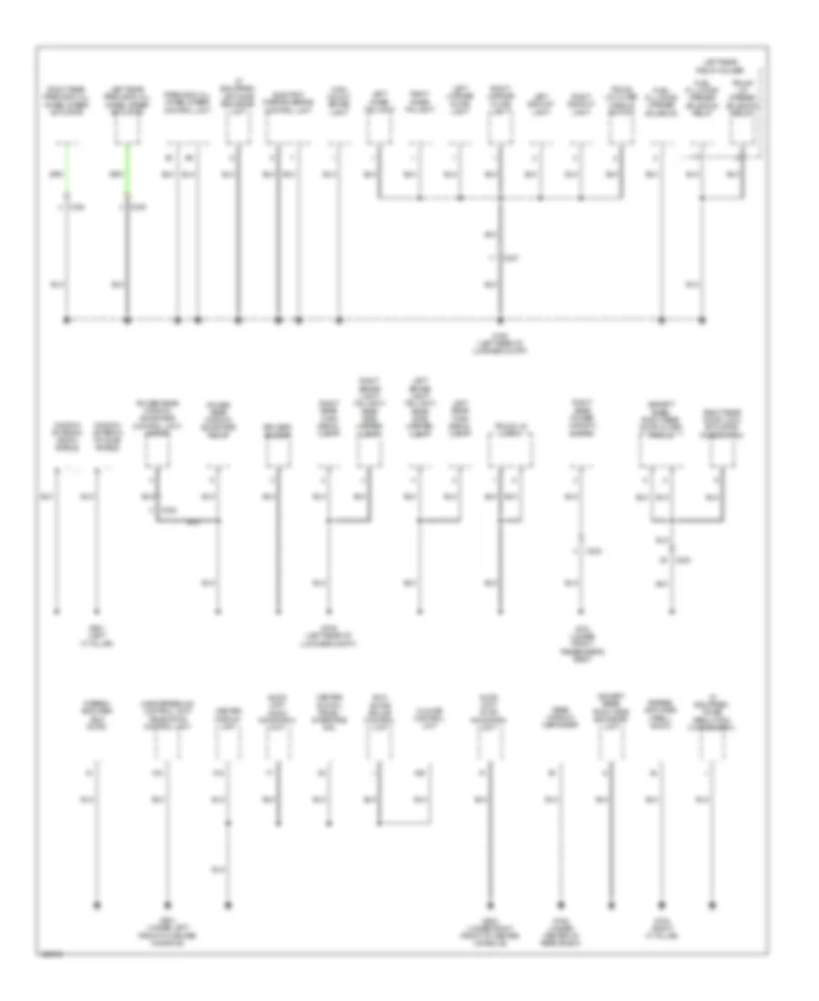
GROUND DISTRIBUTION
Ground Distribution Wiring Diagram (1 of 5) for Acura RLX 2014
List of elements for Ground Distribution Wiring Diagram (1 of 5) for Acura RLX 2014:
- A/t clutch pressure control solenoid valve a
- A/t clutch pressure control solenoid valve b
- A/t clutch pressure control solenoid valve c
- A/t clutch pressure control solenoid valve d
- B11
- B20
- Battery sensor
- C20
- C214
- C408
- C410
- C411
- C413
- C414
- Ckp sensor
- Cmp sensor
- Egr valve/ egr valve position sensor
- Engine
- Engine start/stop switch
- Eps control unit
- G1 (under battery)
- G101 (right front of engine)
- G2 (front of engine)
- G3 (left front of engine compt)
- G402 (left rear corner of engine compt)
- High pressure fuel pump shield
- Ignition coil 1
- Ignition coil 2
- Ignition coil 3
- Ignition coil 4
- Ignition coil 5
- Ignition coil 6
- Injector 1 shield
- Injector 2 shield
- Injector 3 shield
- Injector 4 shield
- Injector 5 shield
- Injector 6 shield
- Junction connector c014 (top rear of engine)
- Junction connector c015 (right side of engine)
- Junction connector c016 (right rear of engine)
- Knock sensor (bank 1) shield
- Knock sensor (bank 2) shield
- Line pressure solenoid valve a
- Pcm
- Power transistor
- Rocker arm oil control solenoid a (bank 1)
- Rocker arm oil control solenoid a (bank 2)
- Rocker arm oil control solenoid b
- Rocker arm oil pressure switch a (bank 1)
- Rocker arm oil pressure switch a (bank 2)
- Shift solenoid valve a
- Shift solenoid valve b
- Shift solenoid valve c
- Transmission housing
- Transmission range switch
Ground Distribution Wiring Diagram (2 of 5) for Acura RLX 2014
List of elements for Ground Distribution Wiring Diagram (2 of 5) for Acura RLX 2014:
- (except base)
- (except base) rear power rear window sunshade switch
- (left side of engine compt) main under-hood fuse box
- (upper left end of dash) driver's under-dash fuse/relay box
- A/t gear position indicator panel
- A16
- A32
- A36
- A37
- Air quality sensor
- Blower motor relay
- C11
- C12
- C13
- C215
- C216
- C223
- Cable reel (in steering column)
- Can gateway
- Console accessory power socket
- Console accessory power socket relay
- Console box light
- Cruise control combination switch
- D12
- Dash lights brightness control switch
- Data link connector (dlc)
- Eld
- Electric parking brake switch
- Front accessory power socket
- Front accessory power socket relay
- G202 (right rear corner of engine compt)
- G301 (left front of engine compt)
- G302 (left front of engine compt)
- G501 (upper left end of dash)
- G503 (lower left center of dash)
- G504 (under center console)
- G701 (under driver's seat)
- Gauge control module
- Left
- Left front side marker light
- Left front turn signal/ parking light
- Left led control unit assembly (high beam)
- Left led control unit assembly (low beam)
- Left rear door lock actuator/ knob switch
- Left rear door outer handle
- Micu
- Paddle shifter + (upshift switch)
- Paddle shifter - (downshift switch)
- Park pin switch/ shift lock solenoid
- Parking & backup sensor control unit
- Power tilt/ telescopic steering control unit
- Rear power window switch
- Relay control module
- Rfc unit
- Security hood switch
- Sport mode switch
- Srs unit
- Steering angle sensor
- Steering heater
- T7 (center of steering wheel)
- Tpms control unit
- Under-hood fuse/relay box shield
- Vsa modulator control unit
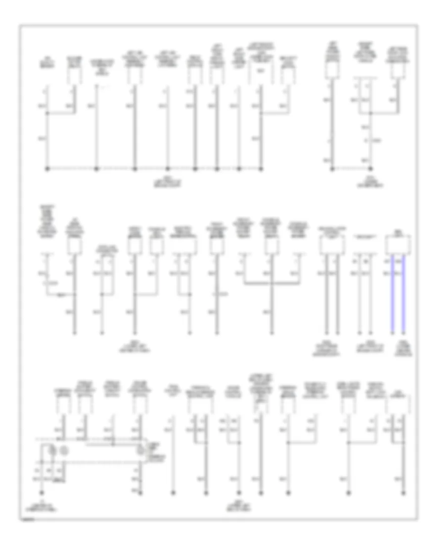
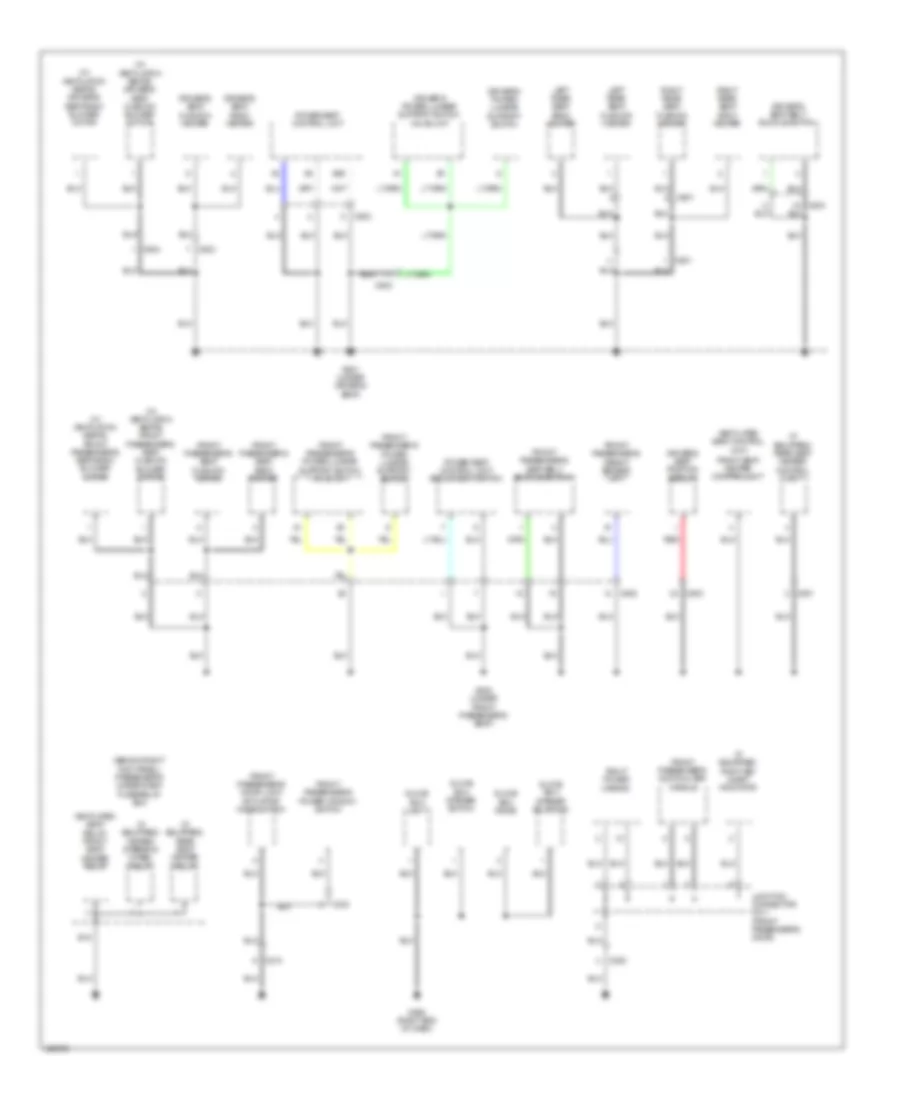
Ground Distribution Wiring Diagram (3 of 5) for Acura RLX 2014
List of elements for Ground Distribution Wiring Diagram (3 of 5) for Acura RLX 2014:
- (except base) automatic lighting/ rain sensor
- (if equipped)
- (if equipped) headlight washer motor
- (if equipped) left bsi alert indicator
- (if equipped) lkas camera/ control unit
- (upper left end of dash) driver's under-dash fuse/relay box
- A17
- Automatic dimming inside mirror
- B15
- Brake fluid level switch
- C205
- C211
- C218
- C301
- C801
- Driver's door lock actuator/ knob switch/ key cylinder switch
- Driver's door outer handle
- Driver's power window motor
- Driver's vanity mirror light
- Driving position memory switch
- Electric steering lock
- Engine mount control unit
- Fcw/ ldw camera unit
- Fuel pump control module
- G201 (right rear corner of engine compt)
- G401 (left rear corner of engine compt)
- G502 (upper left end of dash)
- G702 (under center of rear shelf)
- G703 (under center of rear shelf)
- G704 (left "c" pillar)
- Headlight leveling control unit
- Homelink unit
- Junction connector c010 (driver's door)
- Keyless access control unit
- Left power mirror
- Micu
- Moonroof control unit/ motor
- Multi visor switch
- Noise reduction condenser a
- Noise reduction condenser b
- Passenger's vanity mirror light
- Power mirror control unit
- Power mirror switch
- Power tilt/ telescopic steering control unit
- Power window master switch
- Rear individual map light
- Relay control module
- Right front side marker light
- Right front turn signal/ parking light
- Right led control unit assembly (high beam)
- Right led control unit assembly (low beam)
- Roof console module
- Trunk lid/ fuel fill door opener switch
- Washer fluid level switch
- Windshield washer motor
- Windshield wiper control unit/ motor
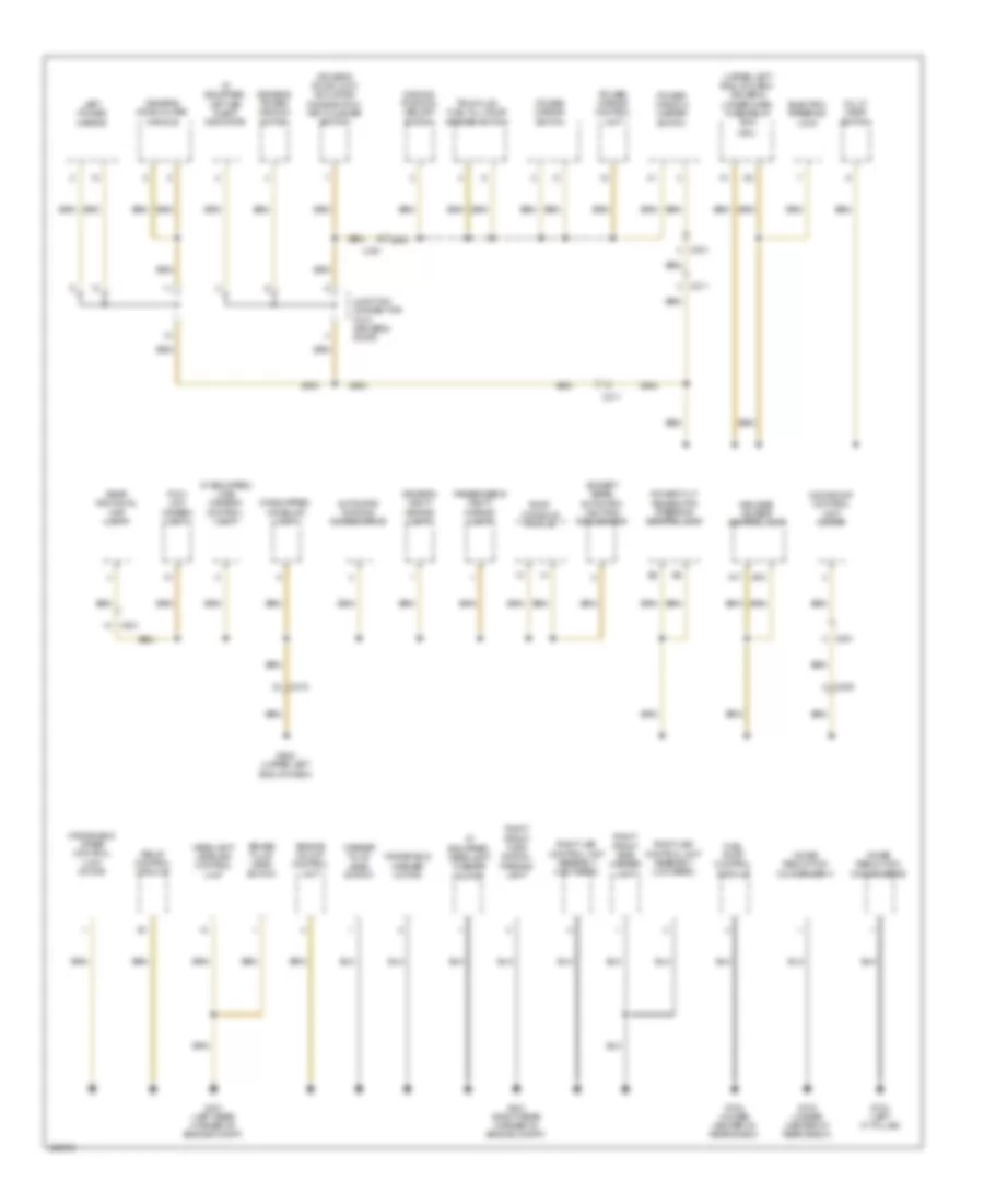
Ground Distribution Wiring Diagram (4 of 5) for Acura RLX 2014
List of elements for Ground Distribution Wiring Diagram (4 of 5) for Acura RLX 2014:
- (except base) right rear door outer handle
- (except base) right side bsi radar unit
- (if equipped) left side bsi radar unit
- (if equipped) noise reduction condenser c
- A12
- A18
- A28
- Anc/ active sound control unit
- Audio unit/ audio navigation unit
- C222
- C223
- C227
- C234
- C235
- Center display unit
- Center switch panel/ interface dial
- Climate control unit
- Electric parking brake control unit
- Fuel fill door opener solenoid
- Fuel fill door opener solenoid relay
- G601 (under left front of center console)
- G602 (under right front of center console)
- G705 (left rear of luggage compt)
- G706 (left rear of luggage compt)
- G751 (under front passenger's seat)
- G752 (under center of rear shelf)
- G753 (right "c" pillar)
- G901 (left "c" pillar)
- Handsfreelink control unit/ telematics control unit
- High mount brake light
- Keyless buzzer
- Left backup light
- Left brake light/ taillight/ rear side marker light
- Left inner taillight
- Left license plate light
- Left rear precision all wheel steer actuator
- Left rear relay holder
- Left rear turn signal light
- Power rear window sunshade control unit/ motor
- Power rear window sunshade relay
- Precision all wheel steer control unit
- Rear power window switch
- Rear window defogger
- Right
- Right backup light
- Right brake light/ taillight/ rear side marker light
- Right inner taillight
- Right license plate light
- Right rear door lock actuator/ knob switch
- Right rear precision all wheel steer actuator
- Right rear turn signal light
- Stereo amplifier (els audio)
- Stereo amplifier (krell audio)
- Trunk lid latch
- Trunk lid opener solenoid relay
- Trunk lid outer handle switch
- Window antenna (am/fm) shield
- Window antenna (fm sub) shield
Ground Distribution Wiring Diagram (5 of 5) for Acura RLX 2014
List of elements for Ground Distribution Wiring Diagram (5 of 5) for Acura RLX 2014:
- (behind right kick panel) passenger's under-dash fuse/relay box
- (if equipped) heated steering wheel relay
- (if equipped) rear seat heater control unit
- (if equipped) rear seat heater relay
- (if equipped) right bsi alert indicator
- (w/ ventilation seats) driver's seat cushion blower motor
- (w/ ventilation seats) driver's seat-back blower motor
- (w/ ventilation seats) front passenger's seat cushion blower motor
- (w/ ventilation seats) front passenger's seat-back blower motor
- B20
- C208
- C210
- C303
- C501
- C502
- C503
- C504
- C601
- Driver's power lumbar support switch
- Driver's power lumbar support switch valve unit
- Driver's seat back heater
- Driver's seat belt buckle switch
- Driver's seat cushion heater
- Driver's seat position sensor
- E18
- Front passenger's door lock actuator/ knob switch
- Front passenger's door outer handle
- Front passenger's power lumbar support switch
- Front passenger's power lumbar support switch valve unit
- Front passenger's power window switch
- Front passenger's seat back heater
- Front passenger's seat belt buckle switch
- Front passenger's seat cushion heater
- Front passenger's weight sensor unit
- Front seat heater control unit
- G505 (right end of dash)
- G801 (under driver's seat)
- G802 (under front passenger's seat)
- Glove box diode
- Glove box light
- Glove box opener solenoid
- Glove box opener switch
- Junction connector c011 (front passenger's door)
- Left rear seat back heater
- Left rear seat cushion heater
- Power seat control unit
- Power seat control unit/ adjustment switch
- Red
- Right power mirror
- Right rear seat back heater
- Right rear seat cushion heater
- Ventilated seat control unit/
- Ventilated seat relay/ front seat heater relay
HEADLIGHTS
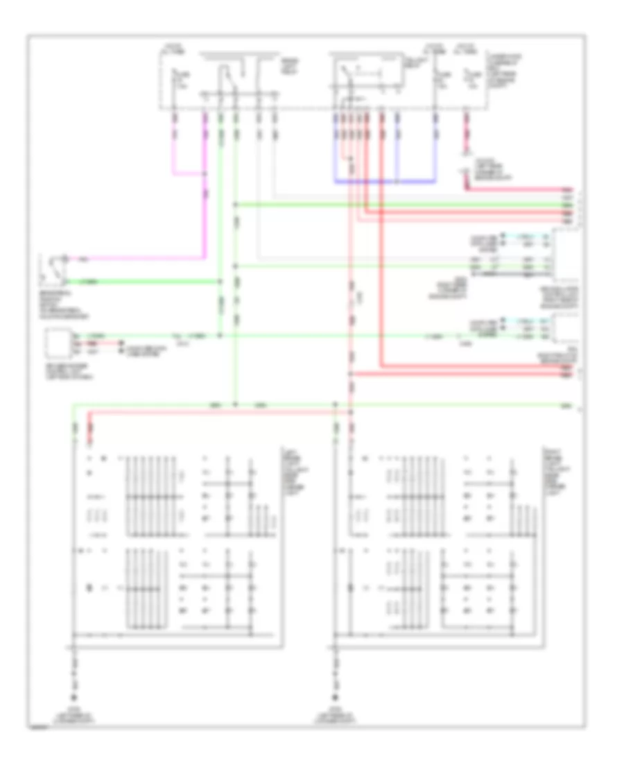
Headlamps Wiring Diagram (1 of 2) for Acura RLX 2014
List of elements for Headlamps Wiring Diagram (1 of 2) for Acura RLX 2014:
- (left rear corner of engine compt) g401
- B12
- B14
- B15
- B16
- C404
- Computer data lines system
- E61
- E83
- E87
- E91
- E93
- E94
- Exterior lights system
- Fuse 10a
- Fuse 15a
- Fuse 3-1 60a
- G201 (right rear corner of engine compt)
- G301 (left front of engine compt)
- Headlight relay
- Hot at all times
- J/c c018 (left rear corner of engine compt)
- Led unit
- Left led control unit assembly (high beam) (rear of left headlight assembly)
- Left led control unit assembly (low beam) (rear of left headlight assembly)
- Main under-hood fuse/relay box (left side of engine compt)
- Pnk
- Red
- Relay control module (in under-hood fuse/relay box)
- Right led control unit assembly (high beam) (rear of right headlight assembly)
- Right led control unit assembly (low beam) (rear of right headlight assembly)
- Under-hood fuse/relay box (left rear of engine compt)
Headlamps Wiring Diagram (2 of 2) for Acura RLX 2014
List of elements for Headlamps Wiring Diagram (2 of 2) for Acura RLX 2014:
- 32bit microcomputer+flash rom
- A25
- A26
- A32
- Air conditioning system
- Auto
- Automatic lighting/ rain sensor (base of interior rearview mirror assembly)
- Automatic lighting/ sunlight sensor (base) (top center of dash)
- B-can h
- B-can l
- B-can transceiver
- C105
- C205
- C406
- Combination light switch
- Computer data lines system
- Cruise lighting dimming circuit
- Dimmer/ flash-to-pass switch
- Driver's junction box 1 (behind left side of dash)
- Driver's junction box 2 (behind left side of dash)
- Driver's under-dash fuse/relay box (under left end of dash)
- E24
- Electric parking brake switch
- Except base
- F18
- F19
- F20
- F23
- Fuse 7.5a
- G501 (upper left end of dash)
- G502 (upper left end of dash)
- G503 (lower left center of dash)
- Gauge control module
- Head
- Headlight switch
- High
- High beam ind
- Hot at all times
- Lights on ind
- Low
- Micu
- Off
- P13
- P15
- P17
- P19
- P20
- P21
- Park
- Pass
- Passenger's under-dash fuse/relay box (behind right kick panel)
- Pnk
- Q10
- Q20
- Red
- Warning driver circuit
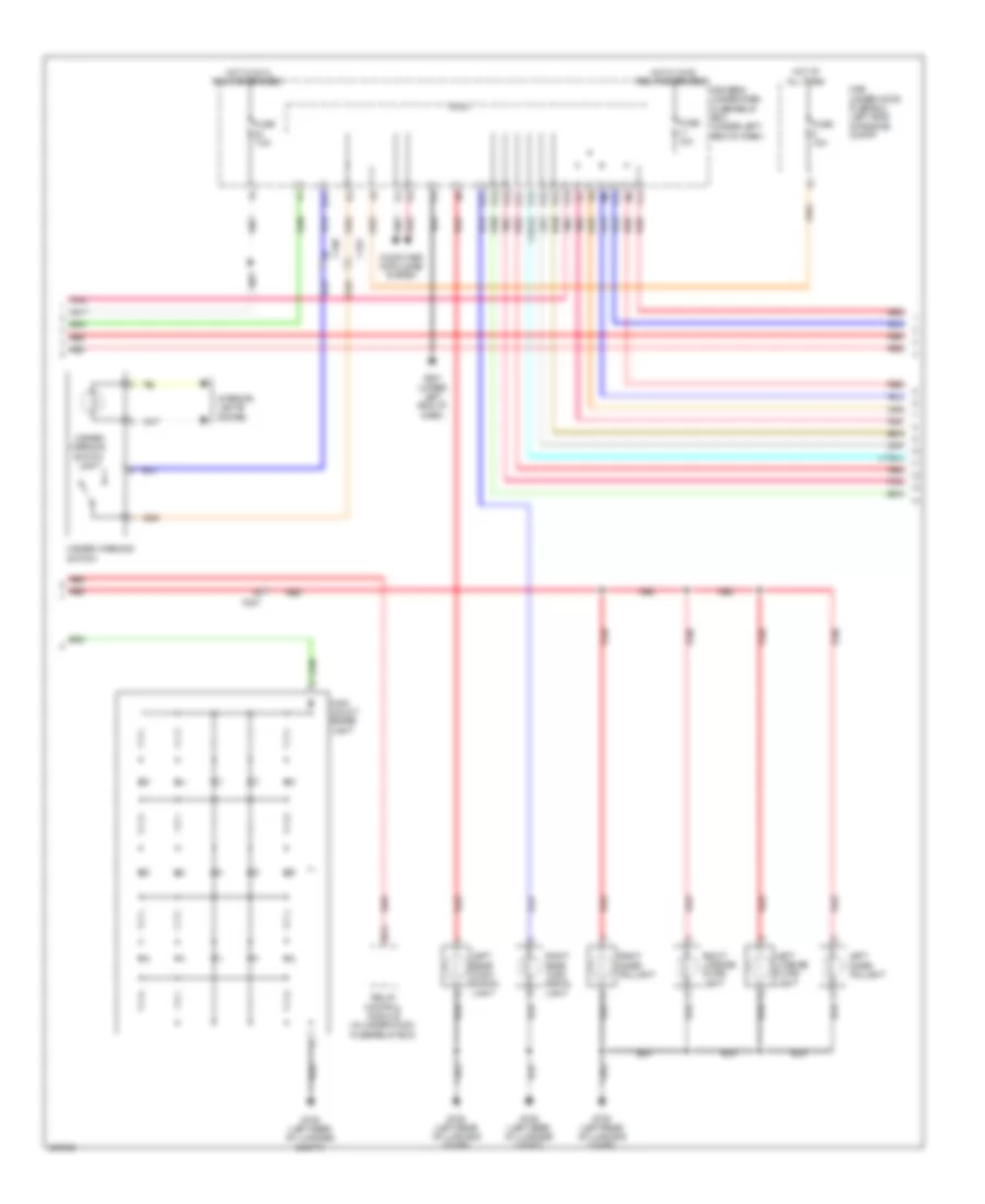
Headlamps Leveling Wiring Diagram for Acura RLX 2014
List of elements for Headlamps Leveling Wiring Diagram for Acura RLX 2014:
- Auto
- Automatic lighting/ rain sensor (base of interior rearview mirror assembly)
- C205
- C232
- C236
- C404
- Combination light switch
- Computer data lines system
- Dimmer/ flash-to-pass switch
- Drive circuit
- Driver's under-dash fuse/relay box (under left end of dash)
- E74
- E83
- Except base
- F23
- Fuse 10a
- Fuse 7.5a
- G401 (left rear corner of engine compt)
- G501 (upper left end of dash)
- Hall ic
- Head
- Headlight leveling control unit (left rear of engine compt)
- Headlight switch
- High
- Hot at all times
- Hot w/ ig1b relay energized
- J/c c018 (left rear corner of engine compt)
- Left headlight leveling motor (behind left headlight assembly)
- Low
- Micu
- Off
- P13
- P15
- P17
- P19
- P20
- P21
- Park
- Pass
- Pnk
- Rear suspension stroke sensor (above center of rear suspension)
- Red
- Right headlight leveling motor (behind right headlight assembly)
- Under-hood fuse/relay box (left rear of engine compt)
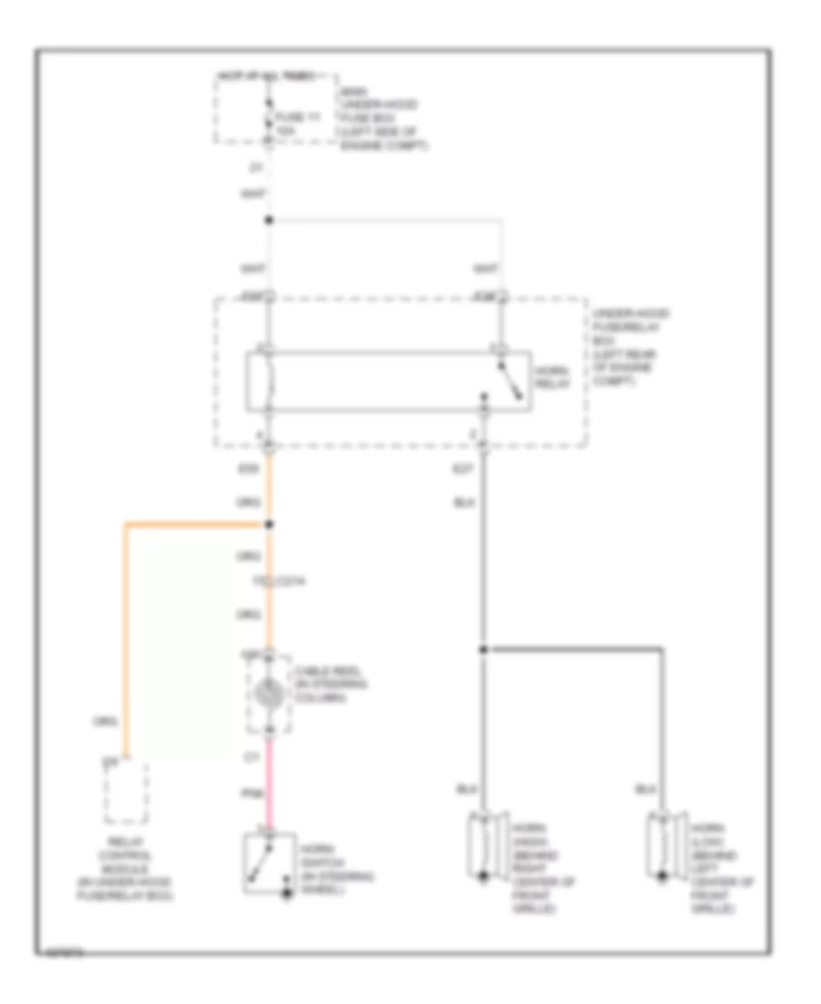
HORN
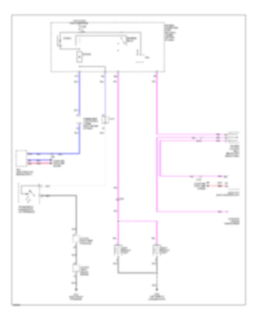
Horn Wiring Diagram for Acura RLX 2014
List of elements for Horn Wiring Diagram for Acura RLX 2014:
- A10
- C214
- Cable reel (in steering column)
- E27
- E28
- E55
- E56
- Fuse 11 10a
- Horn (high) (behind right center of front grille)
- Horn (low) (behind left center of front grille)
- Horn relay
- Horn switch (in steering wheel)
- Hot at all times
- Main under-hood fuse box (left side of engine compt)
- Pnk
- Relay control module (in under-hood fuse/relay box)
- Under-hood fuse/relay box (left rear of engine compt)
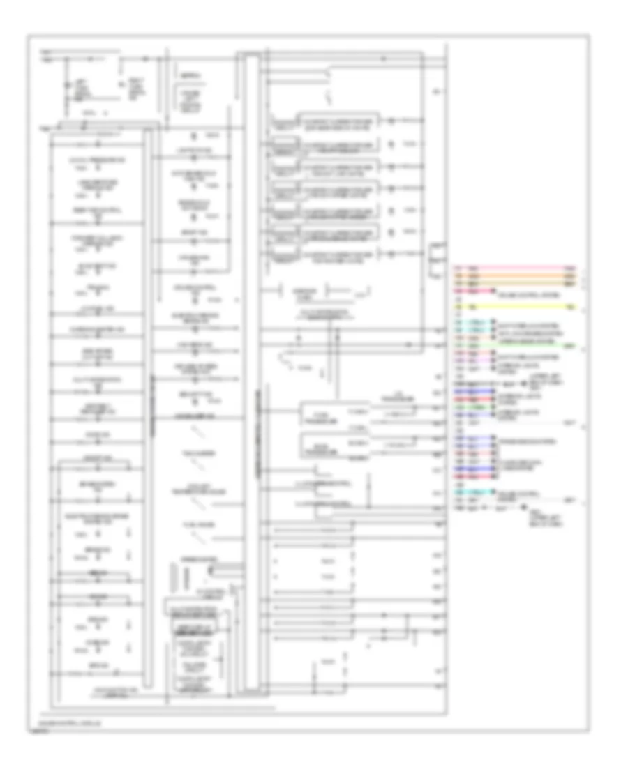
INSTRUMENT CLUSTER
Instrument Cluster Wiring Diagram (1 of 2) for Acura RLX 2014
List of elements for Instrument Cluster Wiring Diagram (1 of 2) for Acura RLX 2014:
- (upper left end of dash) g501
- 3.3v
- 32bit microcomputer + flash rom
- 5v control circuit
- 8mb/32mb flash
- A10
- A11
- A12
- A13
- A14
- A15
- A16
- A17
- A18
- A19
- A20
- A21
- A22
- A23
- A24
- A25
- A26
- A27
- A28
- A29
- A30
- A31
- A32
- Abs ind
- Amp
- Anti-lock brakes system
- Auto brake hold main ind
- B-can h
- B-can l
- B-can transceiver
- Blind spot ind
- Brake hold active ind
- Brake ind
- Brake system ind
- Charging system ind
- Cmbs ind
- Compulsory turning- off circuit
- Compulsory turning- on circuit
- Computer data lines system
- Constant current driver for dial/scale (white)
- Constant current driver for dot lwr (white)
- Constant current driver for dot upper (amber)
- Constant current driver for dot upper (white)
- Constant current driver for gear display (white)
- Constant current driver for pointer (white)
- Constant current driver for tft (color)
- Coolant temperature gauge
- Cruise control ind
- Cruise control system
- Cruise light dimming circuit
- Cruise main ind
- Dimming circuit
- Door ind
- Eeprom
- Electric parking brake ind
- Electric parking brake system ind
- Eps ind
- Exterior lights system
- F-can h
- F-can l
- F-can transceiver
- Fail-safe circuit
- Forward collision warning ind
- Fuel gauge
- G501 (upper left end of dash)
- Gauge control module
- Gear display (segment lcd)
- High beam ind
- Illumination control
- Immobilizer ind
- Interior lights system
- Keyless access system ind
- Lane depature warning ind
- Left turn signal ind
- Lights-on ind
- Lin transceiver
- Low fuel ind
- Low oil pressure ind
- Malfunction ind lamp (mil)
- Multi-information display (dot lcd)
- Multi-information display (tft)
- Multi-information ind
- Pnk
- Rear toe control ind
- Red
- Right turn signal ind
- Seat belt reminder ind
- Security ind
- Shift interlock system
- Side air bag cut-off ind
- Speaker
- Speedometer
- Sport ind
- Srs ind
- Tachometer
- Tpms ind
- Transmissions system
- Vsa ind
- Vsa off ind
- Warning driver circuit
- Wiper/washer system
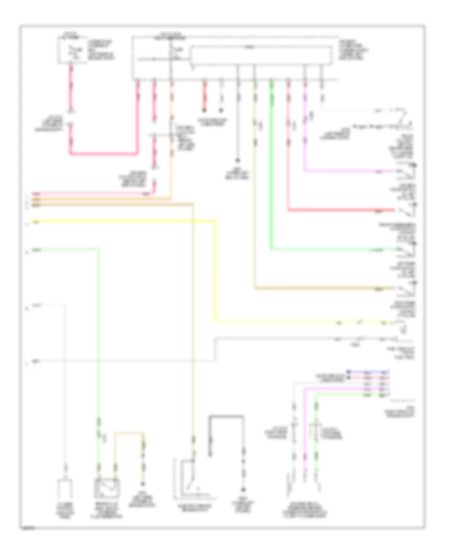
Instrument Cluster Wiring Diagram (2 of 2) for Acura RLX 2014
List of elements for Instrument Cluster Wiring Diagram (2 of 2) for Acura RLX 2014:
- A/t gear position indicator panel
- A10
- B43
- B45
- B47
- Brake fluid level switch (on brake fluid reservoir)
- C212
- C214
- C220
- C224
- Computer data lines system
- Driver's door switch (in left "b" pillar)
- Driver's junction box 1 (behind left side of dash)
- Driver's junction box 2 (behind left side of dash)
- Driver's under-dash fuse/relay box (under left end of dash)
- E23
- E26
- E43
- E83
- Electric parking brake switch
- F23
- Front passenger's door switch (in right "b" pillar)
- Fuel tank unit (top of fuel tank)
- Fuse 10a
- G401 (left rear corner of engine compt)
- G501 (upper left end of dash)
- G503 (lower left center of dash)
- G706 (left rear of luggage compt)
- Hot at all times
- Hot w/ ig1b relay energized
- J/c c014 (top rear of engine)
- J/c c016 (right rear of engine)
- J/c c018 (left rear corner of engine compt)
- Left rear door switch (in left "c" pillar)
- Micu
- Pcm (right front of engine compt)
- Pnk
- Red
- Right rear door switch (in right "c" pillar)
- Rocker arm oil pressure sensor (under intake manifold, in left cylinder bank)
- Trunk lid latch (bottom center rear of luggage compt lid)
- Under-hood fuse/relay box (left rear of engine compt)
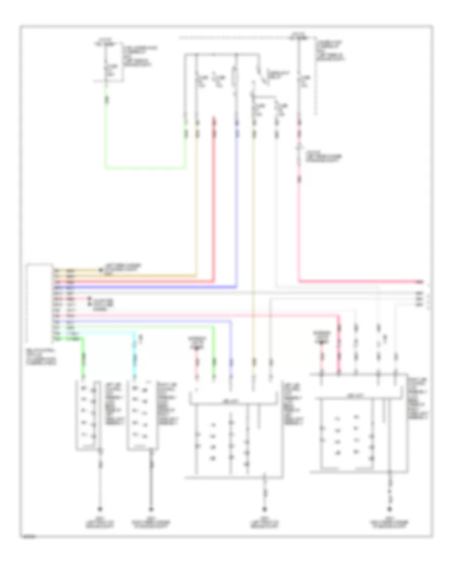
INTERIOR LIGHTS
Courtesy Lamps Wiring Diagram (1 of 2) for Acura RLX 2014
List of elements for Courtesy Lamps Wiring Diagram (1 of 2) for Acura RLX 2014:
- A13
- A16
- C105
- C207
- C208
- C211
- C212
- C214
- C218
- C223
- C224
- C301
- C303
- C305
- Computer data lines system
- Control illumination
- Driver's door courtesy light
- Driver's footwell light
- Driver's junction box 1 (behind left side of dash)
- Driver's junction box 2 (behind left side of dash)
- Driver's under-dash fuse/relay box (under left end of dash)
- Driver's vanity mirror light
- E23
- E26
- E29
- E31
- E38
- E42
- E43
- F10
- F14
- Flash rom microcomputer + 32bit
- Front passenger's door courtesy light
- Front passenger's footwell light
- Fuse 10a
- Fuse 7.5a
- G16
- G501 (upper left end of dash)
- G502 (upper left end of dash)
- Gauge control module
- Hot w/ ig1b relay energized
- Hot w/ taillight relay energized
- J10
- Micu
- Passenger's junction box (upper right center of dash)
- Passenger's under-dash fuse/relay box (behind right kick panel)
- Passenger's vanity mirror light
- Pnk
- Q12
- Red
- Right rear door courtesy light
- Roof console module
Courtesy Lamps Wiring Diagram (2 of 2) for Acura RLX 2014
List of elements for Courtesy Lamps Wiring Diagram (2 of 2) for Acura RLX 2014:
- (in right rear "c" pillar)
- C212
- C213
- C220
- C224
- C227
- C233
- C304
- C801
- Driver's door switch (in driver's "b" pillar)
- E10
- E11
- E39
- E40
- E81
- Front passenger's door switch (in front passenger's "b" pillar)
- Fuse 10a
- G502 (upper left end of dash)
- G706 (left rear of luggage compt)
- Hot at all times
- Interior light cut relay
- Left rear door courtesy light
- Left rear door switch (in left rear "c" pillar)
- Pnk
- Rear individual map light
- Red
- Right rear door switch
- Trunk lid latch (bottom center rear of luggage compt lid)
- Trunk lid light
- Trunk light
- Under-hood fuse/relay box (left rear of engine compt)
Entry Light Timer Wiring Diagram (1 of 2) for Acura RLX 2014
List of elements for Entry Light Timer Wiring Diagram (1 of 2) for Acura RLX 2014:
- C207
- C208
- C211
- C212
- C214
- C218
- C223
- C224
- C301
- C303
- C305
- Computer data lines system
- Driver's door courtesy light
- Driver's junction box 1 (behind left side of dash)
- Driver's under-dash fuse/relay box (under left end of dash)
- Driver's vanity mirror light
- E26
- E31
- E43
- F14
- Front passenger's door courtesy light
- Fuse 10a
- G16
- G502 (upper left end of dash)
- Hot w/ ig1b relay energized
- Micu
- Passenger's junction box (upper right center of dash)
- Passenger's vanity mirror light
- Pnk
- Red
- Right rear door courtesy light
- Roof console module
Entry Light Timer Wiring Diagram (2 of 2) for Acura RLX 2014
List of elements for Entry Light Timer Wiring Diagram (2 of 2) for Acura RLX 2014:
- (in right rear "c" pillar)
- C211
- C212
- C220
- C224
- C301
- C801
- Computer data lines system
- Control block
- Door lock knob
- Driver's door key cylinder switch
- Driver's door lock actuator/knob switch/ key cylinder switch
- Driver's door lock knob switch
- Driver's door switch (in driver's "b" pillar)
- E10
- E11
- E39
- E40
- E81
- Front passenger's door switch (in front passenger's "b" pillar)
- Fuse 10a
- G502 (upper left end of dash)
- Hot at all times
- Interior light cut relay
- Key
- Left rear door switch (in left rear "c" pillar)
- Pnk
- Power window master switch
- Rear individual map light
- Red
- Right rear door switch
- Under-hood fuse/relay box (left rear of engine compt)
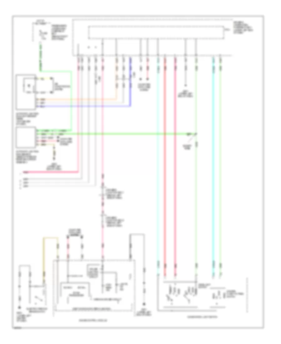
Instrument Illumination Wiring Diagram (1 of 4) for Acura RLX 2014
List of elements for Instrument Illumination Wiring Diagram (1 of 4) for Acura RLX 2014:
- 3.3v
- 32bit microcomputer + flash rom
- A13
- A14
- A16
- A19
- A20
- A25
- A26
- A32
- Auto
- Automatic lighting/rain sensor
- B-can h
- B-can l
- C233
- C705
- Combination light switch
- Computer data lines system
- Constant current driver for dial/scale (white)
- Constant current driver for dot lwr (white)
- Constant current driver for dot upper (amber)
- Constant current driver for dot upper (white)
- Constant current driver for gear display (white)
- Constant current driver for pointer (white)
- Constant current driver for tft (color)
- Dimmer/ flash-to-pass switch
- Dimming circuit
- Driver's under-dash fuse/ relay box (under left end of dash)
- E41
- E83
- Except base
- F23
- Fuse 10a
- Fuse 11 10a
- G10
- G501 (upper left end of dash)
- Gauge control module
- Head
- Head switch
- Hot at all times
- Hot w/ ig1b relay energized
- Illumination control
- J/c c018 (left rear corner of engine compt)
- Left rear door inner handle light
- Micu
- Multiinformation display
- Off
- Off park
- P13
- P15
- P17
- P19
- P20
- P21
- Park auto
- Pass
- Pnk
- Red
- Transceiver b-can
- Under-hood fuse/relay box (left rear of engine compt)
Instrument Illumination Wiring Diagram (2 of 4) for Acura RLX 2014
List of elements for Instrument Illumination Wiring Diagram (2 of 4) for Acura RLX 2014:
- (behind left side of dash) driver's junction box 1
- C211
- C218
- C301
- C801
- Dash lights brightness control switch
- Driver's dashboard side vent light
- Driver's door inner handle light
- Driver's door pocket light
- E10
- F10
- G10
- G501 (upper left end of dash)
- J/c c010 (driver's door)
- J10
- Multi visor switch
- Pnk
- Rear individual map light
- Roof console module
Instrument Illumination Wiring Diagram (3 of 4) for Acura RLX 2014
List of elements for Instrument Illumination Wiring Diagram (3 of 4) for Acura RLX 2014:
- (behind left side of dash) driver's junction box 2
- (under driver's seat) g801
- (under rear of center console) j/c c009
- A/t gear position indicator panel
- A10
- Beverage holder light
- C10
- C215
- C216
- C219
- C501
- Console box light
- Driver's dashboard center vent light
- Electric parking brake switch
- G503 (lower left center of dash)
- G801 (under driver's seat)
- J/c c005 (under front of center console)
- J/c c009 (under rear of center console)
- J10
- Left rear seat heater switch
- Left rear vent light
- Pnk
- Rear power window sunshade switch
- Rear seat heater control module (if equipped)
- Rear temperature control dial
- Right rear seat heater switch
- Right rear vent light
- Sport mode switch
- Utility pocket light
- Ventilated seat control unit/front seat heater control unit (under center console)
Instrument Illumination Wiring Diagram (4 of 4) for Acura RLX 2014
List of elements for Instrument Illumination Wiring Diagram (4 of 4) for Acura RLX 2014:
- (upper right center of dash) passenger's junction box
- 7.5a
- A10
- A12
- C105
- C107
- C208
- C212
- C223
- C303
- Center display unit
- Center switch panel/ interface dial
- Climate control switch
- D10
- D32
- Driver's ventilated seat switch/ driver's seat heater switch
- E10
- E42
- Front passenger's air bag cutoff indicator
- Front passenger's door inner handle light
- Front passenger's door pocket light
- Front passenger's ventilated seat switch/ front passenger's seat heater switch
- Fuse
- G505 (right end of dash)
- G601 (under left front of center console)
- Glove box light
- Glove box opener switch
- Hazard warning switch
- Hot w/ taillight
- J/c c011 (front passenger's door)
- J10
- K10
- Passenger's
- Passenger's dashboard center vent light
- Passenger's dashboard side vent light
- Relay energized
- Right rear door inner handle light
- Under-dash fuse/relay box (behind right kick panel )
- W/ ventilation seat
- W/o ventilation seat
MEMORY SYSTEMS
Driver"s Memory Seat Wiring Diagram (1 of 2) for Acura RLX 2014
List of elements for Driver"s Memory Seat Wiring Diagram (1 of 2) for Acura RLX 2014:
- (behind left side of dash) driver's junction box 1
- A10
- A11
- A12
- A37
- B10
- B11
- B12
- B13
- B14
- B15
- B16
- B17
- B18
- B19
- B20
- C214
- C219
- C239
- C503
- Computer data lines system
- D10
- Driver's seat front up-down motor
- Driver's seat rear up-down motor
- Driver's seat recline motor
- Driver's seat slide motor
- Driver's under-dash fuse/relay box (under left end of dash)
- E13
- E83
- F23
- Fuse 10a
- Fuse 20a
- G501 (upper left end of dash)
- G801 (under driver's seat)
- Hot at all times
- Hot w/ ig1b relay energized
- J/c c018 (left rear corner of engine compt)
- Micu
- Pcm (right front of engine compt)
- Pnk
- Power seat control unit (under outer side of driver's seat)
- Q18
- Red
- Under-hood fuse/relay box (left rear of engine compt)
Driver"s Memory Seat Wiring Diagram (2 of 2) for Acura RLX 2014
List of elements for Driver"s Memory Seat Wiring Diagram (2 of 2) for Acura RLX 2014:
- (behind left side of dash) driver's junction box 2
- (upper right center of dash) passenger's junction box
- B10
- C206
- C209
- C301
- C410
- Computer data lines system
- Driver's under-dash fuse/relay box (under left end of dash)
- Driving position memory switch
- Fuse 7.5a
- G101 (right front of engine)
- G502 (upper left end of dash)
- H10
- Hot w/ ig2 relay energized
- Indicator (led)
- J/c c015 (right side of engine)
- J/c c016 (right rear of engine)
- Pnk
- Position switch
- Power mirror control unit (in driver's door)
- Power tilt/ telescopic steering control unit (on steering column)
- Power window master switch
- Power windows system
- Red
- Set switch
- Transmission range switch (on transaxle)
Memory Mirrors Wiring Diagram (1 of 2) for Acura RLX 2014
List of elements for Memory Mirrors Wiring Diagram (1 of 2) for Acura RLX 2014:
- (behind left side of dash) driver's junction box 1
- (left rear corner of engine compt) j/c c018
- (upper right center of dash) passenger's junction box
- C211
- C301
- C302
- Computer data lines system
- Driver's under-dash fuse/relay box (under left end of dash)
- Driving position memory switch
- E83
- F23
- Fuse 10a
- Fuse 7.5a
- G501 (upper left end of dash)
- G502 (upper left end of dash)
- Hot at all times
- Hot w/ ig2 relay energized
- Indicator (led)
- Left
- Micu
- Pnk
- Position switch
- Power mirror control unit (in driver's door)
- Power mirror switch
- Power windows system
- Red
- Retract
- Right
- Set switch
- Switch 1
- Switch 2
- Switch 3
- Under-hood fuse/relay box (left rear of engine compt)
Memory Mirrors Wiring Diagram (2 of 2) for Acura RLX 2014
List of elements for Memory Mirrors Wiring Diagram (2 of 2) for Acura RLX 2014:
- (behind left side of dash) driver's junction box 2
- (if equipped)
- (under outer side of driver seat) power seat control unit
- B16
- B17
- B18
- C208
- C209
- C210
- C211
- C219
- C301
- C303
- C503
- Computer data lines system
- Defogger
- Defogger system
- Down
- Exterior lights system
- Front passenger power window switch
- Fuse 20a
- G502 (upper left end of dash)
- G505 (right end of dash)
- Hot at all times
- Left
- Left power mirror
- Mirrors system
- Motor actuator
- Passenger's under-dash fuse/relay box (behind right kick panel)
- Pnk
- Position sensor
- Power window master switch
- Red
- Retract actuator
- Retract actuator (if equipped)
- Right
- Right power mirror
- Swing (horizontal)
- Tilt (vertical)
- Turn unit auto
Memory Power Tilt & Power Telescopic Wiring Diagram for Acura RLX 2014
List of elements for Memory Power Tilt & Power Telescopic Wiring Diagram for Acura RLX 2014:
- (behind left side of dash) driver's junction box 1
- (left rear corner of engine compt) j/c c018
- (upper left end of dash) g502
- A10
- A11
- A12
- A13
- A14
- A15
- A16
- B10
- B16
- B17
- B18
- C209
- C219
- C301
- C503
- Computer data lines system
- Down
- Driver's junction box 2 (behind left side of dash)
- Driver's under-dash fuse/relay box (under left end of dash)
- Driving position memory switch
- E83
- F23
- Fuse 10a
- Fuse 20a
- Fuse 7.5a
- G501 (upper left end of dash)
- G502 (upper left end of dash)
- Hot at all times
- Hot w/ ig1b relay energized
- Hot w/ ig2 relay energized
- Indicator (led)
- Micu
- Pnk
- Position switch
- Power mirror control unit (in driver's door)
- Power seat control unit (under outer side of driver seat)
- Power telescopic motor position sensor
- Power tilt motor position sensor
- Power tilt/ telescopic steering control unit (on steering column)
- Power tilt/telescopic steering switch
- Power window master switch
- Power windows system
- Pull
- Push
- Red
- Set switch
- Steering column assembly
- Telescopic switch
- Tilt switch
- Under-hood fuse/relay box (left rear of engine compt)
NAVIGATION
Blind Spot Monitoring Wiring Diagram for Acura RLX 2014
List of elements for Blind Spot Monitoring Wiring Diagram for Acura RLX 2014:
- (driver's door) j/c c010
- (left rear side of luggage compt) left bsi radar unit
- (right rear side of luggage compt) right bsi radar unit
- 3.3v
- 32-bit microcomputer + flash rom
- 5v control unit
- A25
- A26
- A32
- Amp
- B-can transceiver
- B-canh
- B-canl
- Blind spot indicator
- C203
- C208
- C209
- C210
- C212
- C224
- Computer data lines system
- Driver's under-dash fuse/relay box (under left end of dash)
- E33
- Fuse 10a
- Fuse 7.5a
- G501 (upper left end of dash)
- G502 (upper left end of dash)
- G505 (right end of dash)
- G705 (left rear of luggage compt)
- G753 (right "c" pillar)
- Gauge control module
- Hot in on or start
- J/c c011 (front passenger's door)
- Left bsi alert indicator
- Multi- information display (dot lcd)
- Multi- information display (tft)
- Red
- Right bsi alert indicator
- Speaker
- Warning driver circuit
Hands Free Module Wiring Diagram, Base (1 of 2) for Acura RLX 2014
List of elements for Hands Free Module Wiring Diagram, Base (1 of 2) for Acura RLX 2014:
- (right end of dash) handsfreelink control unit/ telematics control unit
- (right side of dash) j/c c002
- +5v
- 5v regulator
- A10
- A11
- A12
- A13
- A14
- A15
- A16
- A17
- A18
- A19
- A20
- A21
- A22
- A23
- A24
- A25
- A26
- A27
- A28
- A29
- A30
- A31
- A32
- C102
- C103
- C11
- C14
- C218
- Cable reel (in steering column)
- Computer data lines system
- Cruise control combination switch
- E82
- Front hfl-anc/active sound control microphone (in roof console)
- Fuse 10a
- Fuse 7.5a
- Fwd switch
- G501 (upper left end of dash)
- Hot at all times
- Ill-
- Lin i/f
- Ljog
- Mcu
- Off hook switch
- On hook/ back switch
- Passenger's under-dash fuse/relay box (behind right kick panel)
- Pnk
- Push switch
- R-sw i/f
- Red
- Rew switch
- Source switch
- Steering commander switch assembly
- Talk switch
- Under-hood fuse/relay box (left rear of engine compt)
Hands Free Module Wiring Diagram, Base (2 of 2) for Acura RLX 2014
List of elements for Hands Free Module Wiring Diagram, Base (2 of 2) for Acura RLX 2014:
- (right "c" pillar) j/c c007
- (right end of dash) j/c c001
- (upper center of dash) j/c c003
- (upper center of dash) j/c c025
- A10
- A11
- A12
- Audio unit/audio-navigation unit
- B12
- C102
- C12
- C701
- D10
- D12
- F13
- F14
- Pnk
- Red
- Remote tuner (under left center of rear shelf)
- Tel/gps/xm antenna
- Usb adapter
- Xm receiver (right front of luggage compt)
Hands Free Module Wiring Diagram, Except Base (1 of 3) for Acura RLX 2014
List of elements for Hands Free Module Wiring Diagram, Except Base (1 of 3) for Acura RLX 2014:
- (under left front of center console) g601
- A10
- A11
- A12
- A13
- A14
- A15
- A16
- A17
- A18
- A19
- A20
- A21
- A22
- A23
- A24
- A25
- A26
- A27
- A28
- A29
- A30
- A31
- A32
- A33
- A34
- A35
- A36
- Assist switch
- C103
- C105
- C214
- C218
- Computer data lines system
- E82
- Front hfl-anc/active sound control microphone (in roof console)
- Fuse 10a
- G502 (upper left end of dash)
- Handsfreelink control unit/telematics control unit (right end of dash)
- Hot at all times
- Link switch
- Pnk
- Red
- Roof console module
- Tel/gps/xm antenna
- Under-hood fuse/relay box (left rear of engine compt)
Hands Free Module Wiring Diagram, Except Base (2 of 3) for Acura RLX 2014
List of elements for Hands Free Module Wiring Diagram, Except Base (2 of 3) for Acura RLX 2014:
- (right side of dash) j/c c002
- +5v
- 5v regulator
- C102
- C11
- C14
- Cable reel (in steering column)
- Center display unit
- Computer data lines system
- Cruise control combination switch
- Fuse 7.5a
- Fwd switch
- G501 (upper left end of dash)
- Hot at all times
- Lin i/f
- Ljog
- Mcu
- Off hook switch
- On hook/ back switch
- Passenger's under-dash fuse/relay box (behind right kick panel)
- Pnk
- Power distribution system
- Push switch
- R-sw i/f
- Red
- Rew switch
- Source switch
- Steering commander switch assembly
- Talk switch
Hands Free Module Wiring Diagram, Except Base (3 of 3) for Acura RLX 2014
List of elements for Hands Free Module Wiring Diagram, Except Base (3 of 3) for Acura RLX 2014:
- (right "c" pillar) j/c c007
- (upper center of dash) j/c c003
- (upper center of dash) j/c c025
- A11
- A12
- A24
- Audio unit/audio-navigation unit
- C102
- C12
- C701
- D10
- F13
- F14
- H11
- J/c c001 (right end of dash)
- Pnk
- Red
- Remote turner
- Usb adapter
- Xm receiver (right front of luggage compt)
Home Link Remote Control Wiring Diagram for Acura RLX 2014
List of elements for Home Link Remote Control Wiring Diagram for Acura RLX 2014:
- Cpu
- E83
- Fuse 16 10a
- G502 upper left end of dash)
- Homelink unit (in roof console)
- Hot at all times
- Pnk
- Red
- Roof console module
- Sw 1
- Sw 2
- Sw 3
- Under-hood fuse/relay box (left rear of engine compt)
Lane Departure Warning Wiring Diagram for Acura RLX 2014
List of elements for Lane Departure Warning Wiring Diagram for Acura RLX 2014:
- 3.3v
- 32-bit microcomputer + flash rom
- 5v control unit
- A27
- A28
- A32
- Amp
- C205
- C207
- C218
- Computer data lines system
- Driver's junction box 1 (behind left side of dash)
- Driver's junction box 2 (behind left side of dash)
- Driver's under-dash fuse/relay box (under left end of dash)
- F-can transceiver
- F-canh
- F-canl
- Fcw/ldw camera unit
- Forward collision warning indicator
- Fuse 10a
- Fuse 7.5a
- G501 (upper left end of dash)
- G502 (upper left end of dash)
- Gauge control module
- Homelink unit (in roof console)
- Hot in on or start
- Interior lights system
- Lane departure warning indicator
- Low off switch
- Micu
- Multi visor switch
- Multi- information display (dot lcd)
- Multi- information display (tft)
- Pnk
- Speaker
- Warning driver circuit
Lane Keeping Assist Wiring Diagram for Acura RLX 2014
List of elements for Lane Keeping Assist Wiring Diagram for Acura RLX 2014:
- 3.3v
- 32-bit microcomputer + flash rom
- 5v control unit
- A27
- A28
- A30
- A32
- Amp
- C16
- C20
- C205
- Cable reel (in steering column)
- Computer data lines system
- Cruise control combination switch
- Driver's junction box 1 (behind left side of dash)
- Driver's junction box 2 (behind left side of dash)
- Driver's under-dash fuse/relay box (under left end of dash)
- E83
- F-can transceiver
- F-canh
- F-canl
- F23
- Fuse 10a
- Fuse 7.5a
- G501 (upper left end of dash)
- G502 (upper left end of dash)
- Gauge control module
- Hot at all times
- Hot in on or start
- Interior lights system
- J/c c018 (left rear corner of engine compt)
- Lkas camera/ control unit (base of interior rearview mirror assembly)
- Lkas switch
- Lkas/distance switch
- Micu
- Multi- information display (dot lcd)
- Multi- information display (tft)
- Pnk
- Speaker
- Under-hood fuse/relay box (left rear of engine compt)
Navigation Wiring Diagram (1 of 9) for Acura RLX 2014
List of elements for Navigation Wiring Diagram (1 of 9) for Acura RLX 2014:
- A10
- A11
- A12
- A13
- A14
- A15
- A16
- A17
- A18
- A19
- A20
- A21
- A22
- A23
- A24
- A49
- Audio unit/audio navigation unit
- C101
- C105
- C106
- C206
- C214
- Clock subdisplay unit
- Computer data lines system
- Driver's under-dash fuse/relay box (under left end of dash)
- E82
- F10
- F11
- F12
- F13
- F14
- F15
- F16
- F17
- F18
- Fuse 10a
- Fuse 7.5a
- G12
- G602
- H10
- H11
- H12
- H13
- H14
- H15
- H16
- Hot at all times
- Hot in on or acc
- Passenger's junction box (upper right center of dash)
- Pcm (right front of engine compt)
- Pnk
- Red
- Under-hood fuse/relay box (left rear of engine compt)
Navigation Wiring Diagram (2 of 9) for Acura RLX 2014
List of elements for Navigation Wiring Diagram (2 of 9) for Acura RLX 2014:
- (behind left side of dash) driver's junction box 2
- (in roof console) front hfl-anc/active sound control microphone
- (left front of luggage compt) electric parking brake control unit
- Anc/active sound control unit (lower center of dash)
- C101
- C102
- C103
- C105
- C203
- C218
- Computer data lines system
- E13
- Fuse 15a
- G601 (under left front of center console)
- Hot at all times
- Passenger's under-dash fuse/relay box (behind right kick panel)
- Pnk
- Rear anc/active sound control microphone (center rear of roof)
- Red
Navigation Wiring Diagram (3 of 9) for Acura RLX 2014
List of elements for Navigation Wiring Diagram (3 of 9) for Acura RLX 2014:
- (right end of dash) j/c c001
- (right rear of luggage compt) stereo amplifier
- B10
- B11
- B12
- B13
- B14
- B15
- B16
- B17
- B18
- C106
- D10
- D11
- D12
- D13
- D14
- D15
- D16
- D17
- D18
- D19
- D20
- D21
- D22
- D23
- D24
- D25
- D26
- D27
- D28
- D29
- D30
- D31
- D32
- G753 (right "c" pillar)
- Pnk
- Red
- Stereo amplifier (right rear of luggage compt)
- Subwoofer
Navigation Wiring Diagram (4 of 9) for Acura RLX 2014
List of elements for Navigation Wiring Diagram (4 of 9) for Acura RLX 2014:
- (right end of dash) handsfree link control unit/telematics control unit
- A14
- A15
- A16
- A21
- A22
- A23
- A24
- A25
- A26
- A27
- A28
- A30
- A32
- A33
- A34
- A35
- A36
- C103
- C210
- C212
- C218
- C223
- C305
- Computer data lines system
- Front passenger's door speaker
- Fuse 28-2 40a
- Hot at all times
- Passenger's under-dash fuse/relay box (behind right kick panel)
- Pnk
- Red
- Right front door tweeter
- Right rear door speaker
- Right rear door tweeter
- Right speaker crossover network control unit
Navigation Wiring Diagram (5 of 9) for Acura RLX 2014
List of elements for Navigation Wiring Diagram (5 of 9) for Acura RLX 2014:
- (upper center of dash) j/c c025
- A10
- A11
- A12
- C105
- Center display unit
- Center switch panel/interface dial
- Driver's junction box 1 (behind left side of dash)
- Driver's under-dash fuse/relay box (under left end of dash)
- Fuse 10a
- Hot in on or start
- Interior lights system
- Keys
- Leds
- Micu
- Multi jog
- Nca
- Pnk
- Red
Navigation Wiring Diagram (6 of 9) for Acura RLX 2014
List of elements for Navigation Wiring Diagram (6 of 9) for Acura RLX 2014:
- (upper center of dash) j/c c003
- Audio unit/audio navigation unit
- C102
- C106
- D10
- D11
- D12
- Exterior lights system
- G10
- G11
- G12
- G13
- G14
- G15
- G16
- G17
- G18
- G19
- G20
- G21
- G22
- G23
- G24
- G901 (left "c" pillar)
- Navigation system
- Nca
- Pnk
- Red
- Tel/gps/xm antenna
- Window antenna (fm sub)
Navigation Wiring Diagram (7 of 9) for Acura RLX 2014
List of elements for Navigation Wiring Diagram (7 of 9) for Acura RLX 2014:
- (left "c" pillar) g901
- (right end of dash) j/c c001
- (right side of dash) j/c c002
- (under left center of rear shelf) remote tuner
- +5v
- 32bit microcomputer + flash rom
- 5v regulator
- A16
- A24
- A25
- A26
- B-can h
- B-can l
- B-can transceiver
- B10
- B12
- C102
- Cable reel (in steering column)
- Computer data lines system
- Cruise light dimming circuit
- Driver's junction box 1 (behind left side of dash)
- Fuse 7.5a
- Fwd
- G501 (upper left end of dash)
- Gauge control module
- Hot at all times
- Lin i/f
- Lin transceiver
- Ljog
- Mcu
- Nca
- Off hook
- On hook/ back
- Passenger's
- Pnk
- Push
- Red
- Rew
- Sig gnd
- Source
- Steering commander switch assembly
- Strg gnd
- Talk
- Under-dash fuse/relay box (behind right kick panel)
- Window antenna (am/fm)
Navigation Wiring Diagram (8 of 9) for Acura RLX 2014
List of elements for Navigation Wiring Diagram (8 of 9) for Acura RLX 2014:
- (right front of luggage compt) xm receiver
- A10
- A11
- A12
- C10
- C102
- C11
- C12
- C13
- C14
- C222
- Front center speaker
- J/c c007 (right "c" pillar)
- Left rear satellite speaker
- Left rear tweeter
- Left speaker crossover network control unit
- Pnk
- Rear speaker crossover network control unit
- Red
- Stereo amplifier (right rear of luggage compt)
Navigation Wiring Diagram (9 of 9) for Acura RLX 2014
List of elements for Navigation Wiring Diagram (9 of 9) for Acura RLX 2014:
- Audio unit/audio navigation unit
- Auxiliary jack assembly
- C10
- C104
- C106
- C11
- C12
- C13
- C14
- C15
- C16
- C17
- C18
- C209
- C211
- C213
- C222
- C233
- C304
- C701
- Driver's door speaker
- Gps antenna
- Left front door tweeter
- Left rear door speaker
- Left rear door tweeter
- Nca
- Pnk
- Red
- Right rear satellite speaker
- Right rear tweeter
- Usb adapter
Parking Assistant Wiring Diagram for Acura RLX 2014
List of elements for Parking Assistant Wiring Diagram for Acura RLX 2014:
- (dot lcd) display information multi-
- (tft) display information multi-
- (upper left end of dash) g501
- 3.3v
- 32-bit microcomputer + flash rom
- A25
- A26
- A27
- A28
- A32
- Amp
- B-canh
- B-canl
- C214
- C220
- C221
- C404
- C405
- C416
- Computer data lines system
- Driver's junction box 1 (behind left side of dash)
- Driver's junction box 2 (behind left side of dash)
- Driver's under-dash fuse/relay box (under left end of dash)
- E83
- F-canh
- F-canl
- F23
- Flash 32mb 8mb/
- Fuse 10a
- Fuse 7.5a
- G14
- G501 (upper left end of dash)
- Gauge control module
- Hot at all times
- Hot in on or start
- J/c c018 (left rear corner of engine compt)
- Left front corner sensor (behind left end of front bumper)
- Left rear center sensor (behind left side of rear bumper)
- Left rear corner sensor (behind left end of rear bumper)
- Micu
- Multi visor switch
- Parking & backup sensor control unit (left center of dash)
- Pnk
- Red
- Right front corner sensor (behind right end of front bumper)
- Right rear center sensor (behind right side of rear bumper)
- Right rear corner sensor (behind right end of rear bumper)
- Speaker
- Transceiver b-can
- Transceiver f-can
- Under-hood fuse/relay box (left rear of engine compt)
- Unit control 5v
Rear Camera Wiring Diagram for Acura RLX 2014
List of elements for Rear Camera Wiring Diagram for Acura RLX 2014:
- Audio unit/ audio navigation unit
- C101
- C213
- C227
- E82
- Fuse 15 10a
- G15
- G16
- G17
- G18
- G602 (under right front of center console)
- Hot at all times
- Rearview camera (center rear of luggage compt lid)
- Red
- Under-hood fuse/relay box (left rear of engine compt)
POWER DISTRIBUTION
Power Distribution Wiring Diagram (1 of 7) for Acura RLX 2014
List of elements for Power Distribution Wiring Diagram (1 of 7) for Acura RLX 2014:
- (left rear of engine compt) under-hood fuse/relay box
- (left side of engine compt) main under-hood fuse box
- (not used)
- A22
- A24
- A36
- Active control engine mount (acm) control relay
- Alternator
- Anc/ active sound control unit
- Audio unit/ audio navigation unit
- B10
- B11
- B14
- Battery
- Battery sensor
- Battery terminal fuse box (on battery positive (+) post)
- Blower motor relay
- C101
- C105
- C19
- C211
- C214
- C218
- C219
- C301
- C401
- C402
- C403
- C503
- Cable reel (in steering column)
- Center display unit
- Data link connector (dlc)
- Driver's junction box 1 (behind left side of dash)
- Driver's junction box 2 (behind left side of dash)
- Driver's under-dash fuse/relay box (under left end of dash)
- E11
- E13
- E19
- E21
- E23
- E28
- E37
- E39
- E49
- E51
- E55
- E75
- E76
- E77
- E78
- E79
- E81
- E82
- E83
- Eld
- Eps control unit
- Etcs control relay
- F23
- Fcw/ ldw camera unit
- Fuse 10a
- Fuse 150a
- Fuse 15a
- Fuse 2-1 30a
- Fuse 2-2 60a
- Fuse 2-3 30a
- Fuse 2-4 50a
- Fuse 2-5 50a
- Fuse 2-6 60a
- Fuse 2-7 40a
- Fuse 2-8 40a
- Fuse 20a
- Fuse 80a
- G1 (under battery)
- G301 (left front of engine compt)
- Gauge control module
- Handsfreelink control unit/ telematics control unit
- Hazard warning switch
- Homelink unit
- Horn relay
- Ignition coil relay
- Interior light cut relay
- J/c c018 (left rear of engine compt)
- Keyless access control unit
- Micu
- Pcm
- Pgm-fi main relay 1
- Pgm-fi sub relay
- Pnk
- Power mirror control unit
- Power seat control unit
- Power tilt/ telescopic steering control unit
- Power window master switch
- Radiator fan relay
- Red
- Relay control module (in under-hood fuse/relay box)
- Starter
- Steering commander switch assembly
- T101
- To c410 (diagram 5 of 7)
- To fuse 3-7 (diagram 2 of 7)
- To passenger's under-dash fuse/relay box (diagram 3 of 7)
- To under-hood fuse/relay box (diagram 4 of 7)
- Vsa modulator control unit
Power Distribution Wiring Diagram (2 of 7) for Acura RLX 2014
List of elements for Power Distribution Wiring Diagram (2 of 7) for Acura RLX 2014:
- (left side of engine compt) main under-hood fuse box
- B13
- Brake light relay
- Brake pedal position switch
- C223
- C226
- C227
- C232
- C403
- C404
- D32
- Driver's under-dash fuse/relay box (under left end of dash)
- E15
- E24
- E31
- E32
- E42
- E59
- E60
- E65
- E66
- E67
- E86
- E87
- E88
- E89
- E91
- Electric parking brake control unit
- From fuse 1 m (diagram 1 of 7)
- Fuel fill door opener solenoid relay
- Fuse 10a
- Fuse 15a
- Fuse 20a
- Fuse 3-1 60a
- Fuse 3-2 60a
- Fuse 3-3 60a
- Fuse 3-5 60a
- Fuse 3-7 40a
- Fuse 3-8 40a
- Fuse 30a
- Fuse 7.5a
- G301 (left front of engine compt)
- Headlight relay
- Injector relay
- Left brake light/ taillight/ rear side marker light
- Left front side marker light
- Left front turn signal/ parking light
- Left inner taillight
- Left led control unit assembly (low beam)
- Left license plate light
- Left rear relay holder a
- Passenger's under-dash fuse/relay box (behind right kick panel)
- Pnk
- Precision all wheel steer control unit
- Rear window defogger relay
- Red
- Relay control module (in under-hood fuse/relay box)
- Right brake light/ taillight/ rear side marker light
- Right front side marker light
- Right front turn signal/ parking light
- Right inner taillight
- Right led control unit assembly (low beam)
- Right license plate light
- Right rear door inner handle light
- Starter cut relay 1
- Taillight relay
- To driver's under-dash fuse/relay box (diagram 3 of 7)
- To driver's under-dash fuse/relay box (diagram 4 of 7)
- To fuse 3-6 (diagram 4 of 7)
- To passenger's junction box (diagram 7 of 7)
- To passenger's under-dash fuse/relay box (diagram 3 of 7)
- Trunk lid opener solenoid relay
- Under-hood fuse/relay box (left rear of engine compt)
- Windshield wiper control unit/ motor
Power Distribution Wiring Diagram (3 of 7) for Acura RLX 2014
List of elements for Power Distribution Wiring Diagram (3 of 7) for Acura RLX 2014:
- (not used)
- (under left end of dash) driver's under-dash fuse/relay box
- A/t gear position indicator panel
- A24
- A35
- Audio unit/ audio navigation unit
- Automatic lighting/ rain sensor (if equipped)
- Base
- C101
- C105
- C106
- C12
- C14
- C205
- C210
- C215
- C223
- C225
- C303
- C502
- Cable reel (in steering column)
- Center display unit
- Center switch panel/ interface dial
- Console accessory power socket
- Console accessory power socket relay (left center of dash)
- D/l dr unlock relay
- D/l lock relay
- D/l unlock relay
- D11
- D15
- Driver's under-dash fuse/relay box (under left end of dash)
- E11
- E13
- E24
- E36
- Electric parking brake control unit
- Except base
- From main under-hood fuse box (diagram 1 of 7)
- From main under-hood fuse box (diagram 2 of 7)
- From under-dash subrelay box (diagram 4 of 7)
- Front accessory power socket
- Front accessory power socket relay (left center of dash)
- Front passenger's power lumbar support switch
- Front passenger's power window switch
- Fuse 10a
- Fuse 15a
- Fuse 20a
- Fuse 28-1 28-2 30a 40a
- Fuse 40a
- Fuse 7.5a
- G12
- G503 (lower left center of dash)
- Glove box opener solenoid relay
- Handsfreelink control unit/ telematics control unit (except base)
- Heated steering wheel relay
- Keyless access control unit
- Micu
- Passenger's junction box (upper right center of dash)
- Passenger's under-dash fuse/relay box (behind right kick panel)
- Pnk
- Power seat control unit/ adjustment switch
- Power tilt/ telescopic steering control unit
- Precision all wheel steer control unit
- Rear seat heater relay
- Red
- Right rear power window switch
- Steering commander switch assembly
- Stereo amplifier
- Tpms control
- Unit
- Ventilated seat relay/ front seat heater relay
Power Distribution Wiring Diagram (4 of 7) for Acura RLX 2014
List of elements for Power Distribution Wiring Diagram (4 of 7) for Acura RLX 2014:
- (left rear of engine compt) under-hood fuse/relay box
- (under left end of dash) driver's under-dash fuse/relay box
- 5v reg
- A/c compressor clutch relay
- A12
- Acc relay
- B12
- B23
- B24
- B25
- B26
- C10
- C11
- C202
- C205
- C209
- C214
- C22
- C226
- C23
- C233
- C239
- C24
- C301
- C410
- C503
- C801
- Driver's junction box 2 (behind left side of dash)
- Driver's power lumbar support switch
- E12
- E13
- E17
- E45
- E84
- E85
- Electric steering lock
- Engine start/stop switch
- From fuse 5 n (diagram 2 of 7)
- From main under-hood fuse box (diagram 1 of 7)
- From main under-hood fuse box (diagram 2 of 7)
- Fuse 10a
- Fuse 15a
- Fuse 20a
- Fuse 3-4 30a
- Fuse 3-6 30a
- Fuse 30a
- Fuse 7.5a
- G101 (right front of engine)
- G15
- Headlight washer relay
- I/f
- Ig1a relay
- Ig1b relay
- Ig2 relay
- Immobilizer
- J/c c015 (right side of engine)
- Keyless access control unit
- Left rear power window switch
- Lf ant
- Main under-hood fuse/relay box (left side of engine compt)
- Moonroof control unit/ motor
- Pnk
- Power rear window sunshade relay
- Power seat control unit
- Power tilt/ telescopic steering control unit
- Power window master switch
- Red
- Relay control module (in under-hood fuse/relay box)
- To driver's under-dash fuse/relay box (diagram 3 of 7)
- To driver's under-dash fuse/relay box (diagram 5 of 7)
- To driver's under-dash fuse/relay box (diagram 6 of 7)
- Under-dash subrelay box (left side of dash)
- Windshield washer motor relay
Power Distribution Wiring Diagram (5 of 7) for Acura RLX 2014
List of elements for Power Distribution Wiring Diagram (5 of 7) for Acura RLX 2014:
- (behind right kick panel) passenger's under-dash fuse/relay box
- (not used)
- (under left end of dash) driver's under-dash fuse/relay box
- A/c compressor clutch relay
- A15
- A18
- A38
- Active control engine mount (acm) control relay
- Air quality sensor
- B28
- Blower motor relay
- Brake light relay
- Brake pedal position switch
- C105
- C202
- C205
- C211
- C214
- C301
- C401
- C410
- Can gateway
- Canada
- Climate control switch
- Climate control unit
- Driver's under-dash fuse/relay box (under left end of dash)
- E17
- E26
- E33
- E35
- E38
- E47
- E53
- E68
- E69
- Engine mount control unit
- Evap canister purge valve
- F13
- F31
- Fcw/ ldw camera unit
- From main under-hood fuse box (diagram 1 of 7)
- From under-dash sub relay box (diagram 4 of 7)
- From under-dash subrelay box (diagram 4 of 7)
- Fuse 10a
- Fuse 15a
- Fuse 20a
- Fuse 30a
- Fuse 7.5a
- Heated steering wheel relay
- J/c c003 (upper center of dash)
- Keyless access control unit
- Lkas camera/ control unit
- Maf/iat sensor
- Multi visor switch (if equipped)
- Passenger's junction box (upper right center of dash)
- Passenger's under-dash fuse/relay box (behind right kick panel)
- Pcm
- Pgm-fi main relay 2
- Pnk
- Power mirror control unit
- Power mirror switch
- Power window master switch
- Precision all wheel steer control unit
- Rear seat heater relay
- Rear window defogger relay
- Red
- Relay control module (in under-hood fuse/relay box)
- Srs unit
- Starter cut relay 1
- Starter cut relay 2
- Steering angle sensor
- Tan
- Under-hood fuse/relay box (left rear of engine compt)
- Usa
- Ventilated seat relay/ front seat heater relay
- Vsa modulator control unit
Power Distribution Wiring Diagram (6 of 7) for Acura RLX 2014
List of elements for Power Distribution Wiring Diagram (6 of 7) for Acura RLX 2014:
- (left rear of engine compt) under-hood fuse/relay box
- (not used)
- (under left end of dash) driver's under-dash fuse/relay box
- A/t gear position indicator panel
- A30
- A39
- Anc/ active sound control unit
- Audio unit/ audio navigation unit
- Automatic dimming inside mirror
- B13
- C101
- C105
- C205
- C216
- C219
- C224
- C240
- C501
- C502
- C503
- Center display unit
- Diode a
- Driver's junction box 1 (behind left side of dash)
- Driver's junction box 2 (behind left side of dash)
- Driver's seat belt tension reducer solenoid
- Driver's ventilated seat switch/ driver's seat heater switch
- E16
- E33
- E73
- E74
- Electric parking brake control unit
- Electric steering lock
- Eps control unit
- F28
- From under-dash sub relay box (diagram 4 of 7)
- Front passenger's airbag cutoff indicator
- Front passenger's seat belt tension reducer solenoid
- Front passenger's ventilated seat switch/ front passenger's seat heater
- Front passenger's weight sensor unit
- Fuse 10a
- Fuse 20a
- Fuse 7.5a
- G14
- Gauge control module
- H10
- Handsfreelink control unit/ telematics control unit (except base)
- Headlight leveling control unit
- J/c c018 (left rear of engine compt)
- Left rear seat heater switch (if equipped)
- Left side bsi radar unit (except base)
- Micu
- Multi visor switch (if equipped)
- Park pin switch/ shift lock solenoid
- Parking & backup sensor control unit
- Passenger's junction box (upper right center of dash)
- Passenger's under-dash fuse/relay box (behind right kick panel)
- Power rear window sunshade relay (except base)
- Power seat control unit
- Power tilt/ telescopic steering control unit
- Rear seat heater control unit
- Red
- Relay control module (in under-hood fuse/relay box)
- Reverse relay
- Right rear seat heater switch (if equipped)
- Right side bsi radar unit (except base)
- Srs unit
- Switch
- Tpms control unit
- Ventilated seat control unit/front seat heater control unit
- W/ ventilation seat
- W/o ventilation seat
- Windshield wiper control unit/ motor
Power Distribution Wiring Diagram (7 of 7) for Acura RLX 2014
List of elements for Power Distribution Wiring Diagram (7 of 7) for Acura RLX 2014:
- A/t gear position indicator panel
- Beverage holder light
- C105
- C107
- C208
- C211
- C215
- C216
- C218
- C219
- C233
- C301
- C303
- C501
- C801
- Center display unit
- Center switch panel/ interface dial
- Climate control switch
- Console box light
- Dash lights brightness control switch
- Driver's dashboard center vent light
- Driver's dashboard side vent light
- Driver's door inner handle light
- Driver's door pocket light
- Driver's junction box 1 (behind left side of dash)
- Driver's junction box 2 (behind left side of dash)
- Driver's under-dash fuse/ relay box (under left end of dash)
- Driver's ventilated seat switch/ driver's seat heater switch
- E41
- Electric parking brake switch
- From passenger's under-dash fuse/relay box (diagram 2 of 7)
- Front passenger's air bag cutoff indicator
- Front passenger's door inner handle light
- Front passenger's door pocket light
- Front passenger's ventilated seat switch/ front passenger's seat heater switch
- G10
- Glove box light
- Glove box opener switch
- Hazard warning switch
- J/c c005 (under front of center console)
- J/c c009 (under rear of center console)
- J/c c010 (driver's door)
- J/c c011 (front passenger's door)
- Left rear door inner handle light
- Left rear seat heater switch
- Left rear vent light
- Multi visor switch
- Passenger's dashboard center vent light
- Passenger's dashboard side vent light
- Passenger's junction box (upper right center of dash)
- Rear individual map light
- Rear power window sunshade switch
- Rear seat heater control unit (if equipped)
- Rear temperature control dial
- Right rear seat heater switch
- Right rear vent light
- Roof console module
- Sport mode switch
- Utility pocket light
- Ventilated seat control unit/front seat heater control unit
- W/ ventilation seat
- W/o ventilation seat
POWER DOOR LOCKS
Power Door Locks Wiring Diagram (1 of 7) for Acura RLX 2014
List of elements for Power Door Locks Wiring Diagram (1 of 7) for Acura RLX 2014:
- (behind left center of rear bumper) keyless buzzer
- (upper right center of dash) passenger's junction box
- A10
- A18
- A25
- A27
- A37
- A38
- Acc relay
- C10
- C11
- C12
- C13
- C14
- C15
- C16
- C17
- C18
- C19
- C20
- C202
- C206
- C21
- C214
- C22
- C23
- C24
- C401
- Computer data lines system
- Driver's junction box 1 (behind left side of dash)
- Driver's junction box 2 (behind left side of dash)
- Electric steering lock (steering column)
- G501 (upper left end of dash)
- G502 (upper left end of dash)
- G706 (left rear of luggage compt)
- Ig1a relay
- Ig1b relay
- Ig2 relay
- Keyless access control unit (left end of dash)
- Park pin switch/ shift lock solenoid (base of shift lever assembly)
- Pcm (right front of engine compt)
- Pnk
- Red
- Under-dash sub-relay box (left side of dash)
Power Door Locks Wiring Diagram (2 of 7) for Acura RLX 2014
List of elements for Power Door Locks Wiring Diagram (2 of 7) for Acura RLX 2014:
- 3.3v
- 32bit microcomputer+flash rom
- 5v control circuit
- 8mb/32mb flash
- A25
- A26
- A32
- B-can h
- B-can l
- B-can transceiver
- C202
- C209
- Computer data lines system
- Door indicator
- Driver's under- dash fuse/ relay box (under left end of dash)
- E11
- E25
- E83
- E86
- Exterior lights system
- F11
- F12
- Fuse 10a
- Fuse 20a
- Fuse 3-4 30a
- Fuse 3-6 30a
- Fuse 7.5a
- G12
- G15
- G501 (upper left end of dash)
- Gauge control module
- Gear display (segment lcd)
- Hot at all times
- Immobilizer indicator
- J/c c018 (left rear corner of engine compt)
- Keyless access system indicator
- Main under-hood fuse/relay box (left side of engine compt)
- Micu
- Multi information indicator
- Multi- information display (dot lcd)
- Multi- information display (tft)
- Pnk
- Q19
- Red
- Security indicator
- Under- hood fuse/ relay box (left rear of engine compt)
- Warning driver circuit
Power Door Locks Wiring Diagram (3 of 7) for Acura RLX 2014
List of elements for Power Door Locks Wiring Diagram (3 of 7) for Acura RLX 2014:
- (on brake pedal mounting bracket) brake pedal position switch
- B15
- B16
- Base
- C212
- C223
- C224
- C233
- Computer data lines system
- D/l door unlock relay
- D/l lock relay
- D/l unlock relay
- Door lock knob
- Door lock knob switch
- Driver's under-dash fuse/ relay box (under left end of dash)
- E14
- E15
- E26
- E28
- E44
- Except base
- F31
- Fuse 10a
- Fuse 20a
- Fuse 7.5a
- G301 (left front of engine compt)
- G501 (upper left end of dash)
- G502 (upper left end of dash)
- G701 (under driver's seat)
- G751 (under front passenger's seat)
- H13
- Hot at all times
- Left rear door lock actuator/knob switch
- Lock
- Micu
- Pnk
- Red
- Relay control module (in under-hood fuse/relay box)
- Right rear door lock actuator/knob switch
- Security hood switch (integral to engine compt hood latch assembly)
- Unlock
Power Door Locks Wiring Diagram (4 of 7) for Acura RLX 2014
List of elements for Power Door Locks Wiring Diagram (4 of 7) for Acura RLX 2014:
- (behind left side of dash) driver's junction box 1
- C207
- C209
- C210
- C212
- C220
- C224
- C301
- C303
- C801
- Control block
- Door lock knob
- Door lock knob switch
- Driver's door key cylinder switch
- Driver's door lock actuator/ knob switch/key cylinder switch
- Driver's door lock knob switch
- Driver's under-dash fuse/relay box (under left end of dash)
- E26
- E43
- F23
- Front passenger's door lock actuator/knob switch
- Front passenger's power window switch
- Fuse 20a
- G502 (upper left end of dash)
- G505 (right end of dash)
- Glove box opener switch
- Hot at all times
- Ind
- Key
- Lock
- Micu
- Moonroof control unit/motor (center rear of roof)
- Passenger's under-dash fuse/relay box (behind right kick panel)
- Pnk
- Q13
- Q18
- Red
- Unlock
Power Door Locks Wiring Diagram (5 of 7) for Acura RLX 2014
List of elements for Power Door Locks Wiring Diagram (5 of 7) for Acura RLX 2014:
- (behind left side of dash) driver's junction box 1
- (in driver's door) power mirror control unit
- (upper right center of dash) passenger's junction box
- C208
- C211
- C214
- C227
- C301
- C410
- Computer data lines system
- Control block
- D10
- Driver's door lock switch
- Driver's door switch (in driver's "b" pillar)
- Front passenger's door switch (in front passenger's "b" pillar)
- G101 (right front of engine)
- G502 (upper left end of dash)
- G705 (left rear of luggage compt)
- Ind
- J/c c015 (right side of engine)
- J/c c016 (right rear of engine)
- Left rear door switch (in left rear "c" pillar)
- Lock
- Pnk
- Power window master switch
- Red
- Right rear door switch (in right rear "c" pillar)
- Transmission range switch (on transaxle)
- Trunk lid outer handle switch
- Unlock
Power Door Locks Wiring Diagram (6 of 7) for Acura RLX 2014
List of elements for Power Door Locks Wiring Diagram (6 of 7) for Acura RLX 2014:
- (except base) left rear door outer handle
- C203
- C208
- C209
- C210
- C212
- C223
- C233
- Door lf antenna
- Driver's door outer handle
- Electric parking brake switch
- Front passenger's door outer handle
- Fuse 7.5a
- G502 (upper left end of dash)
- G503 (lower left center of dash)
- G505 (right end of dash)
- G701 (under driver's seat)
- G751 (under front passenger's seat)
- Glove box opener solenoid relay
- Hot at all times
- Interior lights system
- J/c c011 (front passenger's door)
- Lock switch
- Passenger's under-dash fuse/relay box (behind right kick panel)
- Pnk
- Red
- Right rear door outer handle (except base)
- Touch sensor
Power Door Locks Wiring Diagram (7 of 7) for Acura RLX 2014
List of elements for Power Door Locks Wiring Diagram (7 of 7) for Acura RLX 2014:
- (above left side of glove box) glove box opener solenoid
- (upper left end of dash)
- 5v reg
- A10
- A11
- A12
- A13
- A14
- A15
- A16
- A17
- A18
- A19
- A20
- A21
- A22
- A23
- A24
- A25
- A26
- A27
- A28
- A29
- A30
- A31
- A32
- B10
- B11
- B12
- B13
- B14
- B15
- B16
- B17
- B18
- B19
- B20
- B21
- B22
- B23
- B24
- B25
- B26
- B27
- B28
- C203
- C214
- C220
- C410
- Computer data lines system
- Engine start/stop switch
- Front interior lf antenna (under front of center console)
- G101 (right front of engine)
- G502
- G505 (right end of dash)
- Glove box diode
- I/f
- Immobilizer
- J/c c015 (right side of engine)
- Keyless access control unit (left end of dash)
- Lf ant
- Middle interior lf antenna (under rear of center console)
- Pnk
- Rear bumper lf antenna (behind middle of rear bumper)
- Rear shelf lf antenna (under middle of rear shelf)
- Red
- Rf unit (under center of rear shelf)
- Transmitter
POWER MIRRORS
Power Mirrors Wiring Diagram for Acura RLX 2014
List of elements for Power Mirrors Wiring Diagram for Acura RLX 2014:
- Automatic dimming inside mirror
- C205
- C207
- C208
- C211
- C218
- C410
- Diode a
- Diode b
- Driver's junction box 1 (behind left side of dash)
- Driver's junction box 2 (behind left side of dash)
- Driver's under-dash fuse/relay box (under left end of dash)
- F30
- Fuse 11 10a
- Fuse 7.5a
- G101 (right front of engine)
- G14
- G502 (upper left end of dash)
- Hot w/ ig1b relay energized
- J/c c015 (right side of engine)
- J/c c016 (right rear of engine)
- Left power mirror (if equipped)
- Micu
- Passenger's junction box (upper right center of dash)
- Reverse relay
- Right power mirror (if equipped)
- Transmission range switch (on transaxle)
POWER SEATS
Front Heated Seats Wiring Diagram (1 of 2) for Acura RLX 2014
List of elements for Front Heated Seats Wiring Diagram (1 of 2) for Acura RLX 2014:
- C104
- C105
- C219
- C502
- Driver's junction box 2 (behind left side of dash)
- Driver's under-dash fuse/relay box (under left end of dash)
- Driver's ventilated seat switch/driver's seat heater switch
- Front passenger's seat back heater
- Front passenger's seat cushion heater
- Fuse 7.5a
- G14
- G801 (under driver's seat)
- G802 (under front passenger's seat)
- Heat switch
- Heater indicator (led)
- Hot w/ ig1b relay energized
- Hot w/ ig2 relay energized
- Interior lights system
- Pnk
- Power distribution system
- Red
- Ventilated seat control unit/ front seat heater control unit (under center console)
- Ventilation indicator (led)
- Ventilation switch
- W/ ventilation seat
- W/o ventilation seat
Front Heated Seats Wiring Diagram (2 of 2) for Acura RLX 2014
List of elements for Front Heated Seats Wiring Diagram (2 of 2) for Acura RLX 2014:
- C104
- C225
- C502
- C503
- C504
- Drive ic motor
- Driver's seat back heater
- Driver's seat cushion blower motor (w/ ventilation seat)
- Driver's seat cushion heater
- Driver's seat-back blower motor (w/ ventilation seat)
- E18
- E38
- Front passenger's seat cushion blower motor (w/ ventilation seat)
- Front passenger's seat-back blower motor (w/ ventilation seat)
- Front passenger's ventilated seat switch/front passenger's seat heater switch
- Fuse 2 20a
- G505 (right end of dash)
- G801 (under driver's seat)
- G802 (under front passenger's seat)
- Heat switch
- Heater indicator (led)
- Hot at all times
- Interior lights system
- Motor drive ic
- Passenger's junction box (upper right center of dash)
- Passenger's under-dash fuse/relay box (behind right kick panel)
- Pnk
- Red
- Ventilated seat relay/front seat heater relay
- Ventilation indicator (led)
- Ventilation switch
- W/ ventilation seat
- W/o ventilation seat
Heated Steering Wheel Wiring Diagram for Acura RLX 2014
List of elements for Heated Steering Wheel Wiring Diagram for Acura RLX 2014:
- + flash rom
- 3.3v
- 32bit microcomputer
- A24
- C14
- C19
- Cable reel (in steering column)
- Computer data lines system
- Driver's junction box 1 (behind left side of dash)
- Driver's junction box 2 (behind left side of dash)
- Driver's under-dash fuse/relay box (under left end of dash)
- E18
- E38
- E83
- F23
- Fuse 10a
- Fuse 7.5a
- G501 (upper left end of dash)
- G505 (right end of dash)
- Gauge control module
- Heated steering wheel control unit
- Heated steering wheel relay
- Heated steering wheel switch
- Hot at all times
- Hot w/ ig1b relay energized
- Hot w/ ig2 relay energized
- J/c c018 (left rear corner of engine compt)
- Lin transceiver
- Micu
- Multi- information display (tft)
- Passenger's junction box (upper right center of dash)
- Passenger's under-dash fuse/relay box (behind right kick panel)
- Pnk
- Red
- Steering commander switch assembly
- Steering heater
- Under-hood fuse/relay box (left rear of engine compt)
Lumbar Wiring Diagram for Acura RLX 2014
List of elements for Lumbar Wiring Diagram for Acura RLX 2014:
- Backward
- C225
- C239
- C502
- C503
- Down
- Driver's power lumbar support switch
- Driver's power lumbar support valve unit
- Driver's under-dash fuse/relay box (under left end of dash)
- E12
- Forward
- Front passenger's power lumbar support switch
- Front passenger's power lumbar support valve unit
- Fuse 7.5a
- G801 (under driver's seat)
- G802 (under front passenger's seat)
- Hot at all times
- Passenger's under-dash fuse/relay box (behind right kick panel)
- Pnk
- Red
- Valve unit
Passenger Power Seat Wiring Diagram for Acura RLX 2014
List of elements for Passenger Power Seat Wiring Diagram for Acura RLX 2014:
- Backward
- C225
- C502
- D15
- Down
- Forward
- Front passenger's seat front up-down motor
- Front passenger's seat rear up-down motor
- Front passenger's seat recline motor
- Front passenger's seat slide motor
- Front up-down switch
- Fuse 20a
- G802 (under front passenger's seat)
- Hot at all times
- Passenger's under-dash fuse/relay box (behind right kick panel)
- Power seat control unit/adjustment switch (under outer side of front passenger's seat)
- Rear up-down switch
- Recline switch
- Red
- Slide switch
Rear Heated Seats Wiring Diagram (1 of 2) for Acura RLX 2014
List of elements for Rear Heated Seats Wiring Diagram (1 of 2) for Acura RLX 2014:
- C216
- C219
- C501
- C601
- Driver's under-dash fuse/relay box (under left end of dash)
- Fuse 7.5a
- G14
- G801 (under driver's seat)
- Heat switch
- Heater indicator (led)
- Hot w/ ig1b relay energized
- Hot w/ ig2 relay energized
- Interior lights system
- Left rear seat heater switch
- Pnk
- Rear seat heater control unit (behind left rear seat)
- Red
- Right rear seat back heater
- Right rear seat cushion heater
Rear Heated Seats Wiring Diagram (2 of 2) for Acura RLX 2014
List of elements for Rear Heated Seats Wiring Diagram (2 of 2) for Acura RLX 2014:
- C216
- C219
- C225
- C601
- D18
- E18
- E38
- Fuse 9 20a
- G505 (right end of dash)
- G801 (under driver's seat)
- Heat switch
- Heater indicator (led)
- Hot at all times
- Interior lights system
- Left rear seat back heater
- Left rear seat cushion heater
- Passenger's junction box (upper right center of dash)
- Passenger's under-dash fuse/relay box (behind right kick panel)
- Pnk
- Rear seat heater relay
- Red
- Right rear seat heater switch
POWER TOP/SUNROOF
Power Top/Sunroof Wiring Diagram for Acura RLX 2014
List of elements for Power Top/Sunroof Wiring Diagram for Acura RLX 2014:
- (center rear of roof) moonroof control unit/motor
- (left rear corner of engine compt) j/c c018
- C205
- C207
- C208
- C211
- C212
- C220
- C301
- C303
- C801
- Computer data lines system
- Control block
- Cpu
- Driver's door key cylinder switch
- Driver's door lock actuator/knob switch/key cylinder switch
- Driver's door switch (in driver's "b" pillar)
- Driver's under-dash fuse/relay box (under left end of dash)
- E83
- F23
- Front passenger's door switch (in front passenger's "b" pillar)
- Front passenger's power window switch
- Fuse 16 10a
- Fuse 16 20a
- G502 (upper left end of dash)
- Hole sensor
- Hot at all times
- Input circuit
- Interior lights system
- Key
- Lock
- Micu
- Moonroof close relay
- Moonroof motor
- Moonroof open relay
- Passenger's junction box (upper right center of dash)
- Pnk
- Power window master switch
- Red
- Reg
- Roof console module 0) off 1) open 2) close 3) auto open 4) auto close
- Tilt
- Under-hood fuse/relay box (left rear of engine compt)
- Unlock
POWER WINDOWS
Power Windows Wiring Diagram (1 of 2) for Acura RLX 2014
List of elements for Power Windows Wiring Diagram (1 of 2) for Acura RLX 2014:
- (except base) left power mirror
- (except base) right power mirror
- As switch
- Auto
- C209
- C211
- C301
- Computer data lines system
- Control block
- Defogger system
- Door lock switch
- Down
- Dr switch
- Driver's door lock actuator/knob switch/ key cylinder switch
- Driver's power window motor
- Driver's under-dash fuse/relay box (under left end of dash)
- E83
- Except base
- Front passenger's door lock actuator/ knob switch
- Fuse 10a
- Fuse 20a
- Fuse 7.5a
- G502 (upper left end of dash)
- Hot at all times
- Hot w/ ig2 relay energized
- Ind
- J/c c010 (driver's door)
- Lock
- Main
- Main switch
- Pnk
- Power window master switch
- Pulser
- Red
- Rl switch
- Rr switch
- Un lock
- Under-hood fuse/relay box (left rear of engine compt)
- Unlock
Power Windows Wiring Diagram (2 of 2) for Acura RLX 2014
List of elements for Power Windows Wiring Diagram (2 of 2) for Acura RLX 2014:
- As switch
- Auto
- C208
- C210
- C213
- C223
- C233
- C303
- Computer data lines system
- Control block
- Control unit
- D11
- D33
- Defogger system
- Door lock switch
- Down
- Driving position memory switch
- E41
- Front passenger's power window motor
- Front passenger's power window switch
- Fuse 20a
- G502 (upper left end of dash)
- G505 (right end of dash)
- G701 (under driver's seat)
- G751 (under front passenger's seat)
- Hot at all times
- Ill
- Interior lights system
- Left rear power window motor
- Left rear power window switch
- Lock
- Passenger's junction box (upper right center of dash)
- Passenger's under-dash fuse/relay box (behind right kick panel)
- Pnk
- Power mirror switch
- Pulser
- Rear switch
- Red
- Right rear power window motor
- Right rear power window switch
- Trunk lid/ fuel fill door opener switch
- Unlock
Rear Window Sun Shade Wiring Diagram for Acura RLX 2014
List of elements for Rear Window Sun Shade Wiring Diagram for Acura RLX 2014:
- (left rear of luggage compt) g706
- (upper left end of dash) g502
- A/t gear position indicator panel
- A10
- A16
- A37
- B10
- B11
- B23
- B30
- B38
- C205
- C206
- C212
- C214
- C216
- C222
- C226
- C401
- C410
- Computer data lines system
- D10
- Driver's junction box 1 (behind left side of dash)
- Driver's junction box 2 (behind left side of dash)
- Driver's under-dash fuse/relay box (under left end of dash)
- E22
- E23
- E33
- E51
- E52
- E77
- F30
- Front power rear window sunshade switch
- Fuse 15a
- Fuse 20a
- Fuse 7.5a
- G101 (right front of engine)
- G503 (lower left center of dash)
- G753 (right "c" pillar)
- H10
- Hot at all times
- Hot w/ ig1b relay energized
- Interior lights system
- J/c c015 (right side of engine)
- J/c c016 (right rear of engine)
- Micu
- Noise reduction condenser c (under right end of rear shelf)
- Passenger's junction box (upper right center of dash) d4
- Pcm (right front of engine compt)
- Pgm-fi main relay 1
- Pnk
- Power rear window sunshade control unit/motor (under center rear of rear shelf)
- Power rear window sunshade relay (under left end of rear shelf)
- Q18
- Rear power window sunshade switch
- Red
- Roof console module
- Transmission range switch (on transaxle)
- Under-hood fuse/relay box (left rear of engine compt)
RADIO
Radio Wiring Diagram, with Navigation (1 of 9) for Acura RLX 2014
List of elements for Radio Wiring Diagram, with Navigation (1 of 9) for Acura RLX 2014:
- A10
- A11
- A12
- A13
- A14
- A15
- A16
- A17
- A18
- A19
- A20
- A21
- A22
- A23
- A24
- A49
- Audio unit/audio navigation unit
- C101
- C105
- C106
- C206
- C214
- Clock subdisplay unit
- Computer data lines system
- Driver's under-dash fuse/relay box (under left end of dash)
- E82
- F10
- F11
- F12
- F13
- F14
- F15
- F16
- F17
- F18
- Fuse 10a
- Fuse 7.5a
- G12
- G602
- H10
- H11
- H12
- H13
- H14
- H15
- H16
- Hot at all times
- Hot in on or acc
- Passenger's junction box (upper right center of dash)
- Pcm (right front of engine compt)
- Pnk
- Red
- Under-hood fuse/relay box (left rear of engine compt)
Radio Wiring Diagram, with Navigation (2 of 9) for Acura RLX 2014
List of elements for Radio Wiring Diagram, with Navigation (2 of 9) for Acura RLX 2014:
- (behind left side of dash) driver's junction box 2
- (in roof console) front hfl-anc/active sound control microphone
- (left front of luggage compt) electric parking brake control unit
- Anc/active sound control unit (lower center of dash)
- C101
- C102
- C103
- C105
- C203
- C218
- Computer data lines system
- E13
- Fuse 15a
- G601 (under left front of center console)
- Hot at all times
- Passenger's under-dash fuse/relay box (behind right kick panel)
- Pnk
- Rear anc/active sound control microphone (center rear of roof)
- Red
Radio Wiring Diagram, with Navigation (3 of 9) for Acura RLX 2014
List of elements for Radio Wiring Diagram, with Navigation (3 of 9) for Acura RLX 2014:
- (right end of dash) j/c c001
- (right rear of luggage compt) stereo amplifier
- B10
- B11
- B12
- B13
- B14
- B15
- B16
- B17
- B18
- C106
- D10
- D11
- D12
- D13
- D14
- D15
- D16
- D17
- D18
- D19
- D20
- D21
- D22
- D23
- D24
- D25
- D26
- D27
- D28
- D29
- D30
- D31
- D32
- G753 (right "c" pillar)
- Pnk
- Red
- Stereo amplifier (right rear of luggage compt)
- Subwoofer
Radio Wiring Diagram, with Navigation (4 of 9) for Acura RLX 2014
List of elements for Radio Wiring Diagram, with Navigation (4 of 9) for Acura RLX 2014:
- (right end of dash) handsfree link control unit/telematics control unit
- A14
- A15
- A16
- A21
- A22
- A23
- A24
- A25
- A26
- A27
- A28
- A30
- A32
- A33
- A34
- A35
- A36
- C103
- C210
- C212
- C218
- C223
- C305
- Computer data lines system
- Front passenger's door speaker
- Fuse 28-2 40a
- Hot at all times
- Passenger's under-dash fuse/relay box (behind right kick panel)
- Pnk
- Red
- Right front door tweeter
- Right rear door speaker
- Right rear door tweeter
- Right speaker crossover network control unit
Radio Wiring Diagram, with Navigation (5 of 9) for Acura RLX 2014
List of elements for Radio Wiring Diagram, with Navigation (5 of 9) for Acura RLX 2014:
- (upper center of dash) j/c c025
- A10
- A11
- A12
- C105
- Center display unit
- Center switch panel/interface dial
- Driver's junction box 1 (behind left side of dash)
- Driver's under-dash fuse/relay box (under left end of dash)
- Fuse 10a
- Hot in on or start
- Interior lights system
- Keys
- Leds
- Micu
- Multi jog
- Nca
- Pnk
- Red
Radio Wiring Diagram, with Navigation (6 of 9) for Acura RLX 2014
List of elements for Radio Wiring Diagram, with Navigation (6 of 9) for Acura RLX 2014:
- (upper center of dash) j/c c003
- Audio unit/audio navigation unit
- C102
- C106
- D10
- D11
- D12
- Exterior lights system
- G10
- G11
- G12
- G13
- G14
- G15
- G16
- G17
- G18
- G19
- G20
- G21
- G22
- G23
- G24
- G901 (left "c" pillar)
- Navigation system
- Nca
- Pnk
- Red
- Tel/gps/xm antenna
- Window antenna (fm sub)
Radio Wiring Diagram, with Navigation (7 of 9) for Acura RLX 2014
List of elements for Radio Wiring Diagram, with Navigation (7 of 9) for Acura RLX 2014:
- (left "c" pillar) g901
- (right end of dash) j/c c001
- (right side of dash) j/c c002
- (under left center of rear shelf) remote tuner
- +5v
- 32bit microcomputer + flash rom
- 5v regulator
- A16
- A24
- A25
- A26
- B-can h
- B-can l
- B-can transceiver
- B10
- B12
- C102
- Cable reel (in steering column)
- Computer data lines system
- Cruise light dimming circuit
- Driver's junction box 1 (behind left side of dash)
- Fuse 7.5a
- Fwd
- G501 (upper left end of dash)
- Gauge control module
- Hot at all times
- Lin i/f
- Lin transceiver
- Ljog
- Mcu
- Nca
- Off hook
- On hook/ back
- Passenger's
- Pnk
- Push
- Red
- Rew
- Sig gnd
- Source
- Steering commander switch assembly
- Strg gnd
- Talk
- Under-dash fuse/relay box (behind right kick panel)
- Window antenna (am/fm)
Radio Wiring Diagram, with Navigation (8 of 9) for Acura RLX 2014
List of elements for Radio Wiring Diagram, with Navigation (8 of 9) for Acura RLX 2014:
- (right front of luggage compt) xm receiver
- A10
- A11
- A12
- C10
- C102
- C11
- C12
- C13
- C14
- C222
- Front center speaker
- J/c c007 (right "c" pillar)
- Left rear satellite speaker
- Left rear tweeter
- Left speaker crossover network control unit
- Pnk
- Rear speaker crossover network control unit
- Red
- Stereo amplifier (right rear of luggage compt)
Radio Wiring Diagram, with Navigation (9 of 9) for Acura RLX 2014
List of elements for Radio Wiring Diagram, with Navigation (9 of 9) for Acura RLX 2014:
- Audio unit/audio navigation unit
- Auxiliary jack assembly
- C10
- C104
- C106
- C11
- C12
- C13
- C14
- C15
- C16
- C17
- C18
- C209
- C211
- C213
- C222
- C233
- C304
- C701
- Driver's door speaker
- Gps antenna
- Left front door tweeter
- Left rear door speaker
- Left rear door tweeter
- Nca
- Pnk
- Red
- Right rear satellite speaker
- Right rear tweeter
- Usb adapter
Radio Wiring Diagram, without Navigation (1 of 8) for Acura RLX 2014
List of elements for Radio Wiring Diagram, without Navigation (1 of 8) for Acura RLX 2014:
- (behind left side of dash) driver's junction box 2
- (left front of luggage compt) electric parking brake control unit
- (under left front of center console) g601
- A10
- A11
- A12
- A13
- A14
- A15
- A16
- A17
- A18
- A19
- A20
- A21
- A22
- A23
- A24
- A49
- Audio unit/audio navigation unit
- C101
- C105
- C203
- C206
- C214
- Clock subdisplay unit
- Computer data lines system
- E82
- F10
- F11
- F12
- F13
- F14
- F15
- F16
- F17
- F18
- Fuse 10a
- G602 (under right front of center console)
- H10
- H11
- H12
- H13
- H14
- H15
- H16
- H17
- H18
- Hot at all times
- Passenger's junction box (upper right center of dash)
- Pcm (right front of engine compt)
- Pnk
- Red
- Under-hood fuse/relay box (left rear of engine compt)
Radio Wiring Diagram, without Navigation (2 of 8) for Acura RLX 2014
List of elements for Radio Wiring Diagram, without Navigation (2 of 8) for Acura RLX 2014:
- (behind left side of dash)
- A10
- A11
- A12
- A13
- A14
- A15
- A16
- A17
- A18
- C101
- C102
- C105
- C106
- C209
- C213
- C223
- C233
- Driver's door speaker
- Driver's junction box 1
- Driver's under-dash fuse/relay box (under left end of dash)
- E13
- Fuse 10a
- Fuse 15a
- Fuse 28-1 30a
- Fuse 7.5a
- G12
- G601 (under left front of center console)
- Hot at all times
- Hot in on or acc
- Hot in on or start
- Micu
- Passenger's under-dash fuse/relay box (behind right kick panel)
- Pnk
- Red
- Right rear door speaker
- Stereo amplifier (right rear of luggage compt)
- Subwoofer
Radio Wiring Diagram, without Navigation (3 of 8) for Acura RLX 2014
List of elements for Radio Wiring Diagram, without Navigation (3 of 8) for Acura RLX 2014:
- (right end of dash) j/c c001
- (right rear of luggage compt) stereo amplifier
- B10
- B11
- B12
- B13
- B14
- B15
- B16
- B17
- B18
- B19
- B20
- B21
- B22
- B23
- B24
- B25
- B26
- B27
- B28
- C101
- C103
- C210
- C211
- C213
- C222
- C233
- C304
- C305
- Front center speaker
- Front passenger's door speaker
- Left front door tweeter
- Left rear door speaker
- Left rear door tweeter
- Left rear satellite
- Left rear tweeter
- Pnk
- Red
- Right front door tweeter
- Right rear door tweeter
- Right rear satellite
- Right rear tweeter
- Speaker
Radio Wiring Diagram, without Navigation (4 of 8) for Acura RLX 2014
List of elements for Radio Wiring Diagram, without Navigation (4 of 8) for Acura RLX 2014:
- (right end of dash) handsfree link control unit/telematics control unit
- A12
- A13
- A14
- A16
- A17
- A18
- A19
- A20
- A21
- A22
- A23
- A24
- A28
- A32
- Anc/active sound control unit (lower center of dash)
- C103
- C218
- Center switch panel/interface dial
- Computer data lines system
- Front hfl-anc/active sound control microphone (in roof console)
- G601 (under left front of center console)
- Interior lights system
- Keys
- Leds
- Multi jog
- Pnk
- Rear anc/active sound control microphone (center rear of roof)
- Red
Radio Wiring Diagram, without Navigation (5 of 8) for Acura RLX 2014
List of elements for Radio Wiring Diagram, without Navigation (5 of 8) for Acura RLX 2014:
- (right front of luggage compt) xm receiver
- (upper center of dash) j/c c003
- (upper center of dash) j/c c025
- A10
- A11
- A12
- C102
- J/c c002 (right side of dash)
- J/c c007 (right "c" pillar)
- Pnk
- Red
- Tel/gps/xm antenna
Radio Wiring Diagram, without Navigation (6 of 8) for Acura RLX 2014
List of elements for Radio Wiring Diagram, without Navigation (6 of 8) for Acura RLX 2014:
- A10
- A11
- A12
- Audio unit/audio navigation unit
- C102
- Center display unit
- D10
- D11
- D12
- Exterior lights system
- G10
- G11
- G12
- G13
- G14
- G15
- G16
- G17
- G18
- G19
- G20
- G21
- G22
- G23
- G24
- G601 (under left front of center console)
- Interior lights system
- J/c c001 (right end of dash)
- Navigation system
- Nca
- Pnk
- Red
Radio Wiring Diagram, without Navigation (7 of 8) for Acura RLX 2014
List of elements for Radio Wiring Diagram, without Navigation (7 of 8) for Acura RLX 2014:
- (behind left side of dash) driver's junction box 1
- +5v
- 32bit microcomputer + flash rom
- 5v regulator
- A16
- A24
- A25
- A26
- B-can h
- B-can l
- Cable reel (in steering column)
- Circuit dimming light cruise
- Computer data lines system
- Fuse 7.5a
- Fwd
- G501 (upper left end of dash)
- Gauge control module
- Hot at all times
- Lin i/f
- Ljog
- Mcu
- Off hook
- On hook/ back
- Passenger's underdash fuse/relay box (behind right kick panel)
- Pnk
- Push
- Red
- Rew
- Sig gnd
- Source
- Steering commander switch assembly
- Strg gnd
- Talk
- Transceiver b-can
- Transceiver lin
Radio Wiring Diagram, without Navigation (8 of 8) for Acura RLX 2014
List of elements for Radio Wiring Diagram, without Navigation (8 of 8) for Acura RLX 2014:
- Audio unit/audio navigation unit
- Auxiliary jack assembly
- B10
- B12
- C10
- C102
- C104
- C11
- C12
- C13
- C14
- C15
- C16
- C17
- C18
- C19
- C20
- C701
- Computer data lines system
- G901 (left "c" pillar)
- J10
- J11
- J12
- J13
- J14
- J15
- J16
- J17
- J18
- Nca
- Pnk
- Red
- Remote tuner (under left center of rear shelf)
- Usb adapter
- Window antenna (am/fm)
- Window antenna (fm sub)
SHIFT INTERLOCK
Park Brake Release Wiring Diagram (1 of 2) for Acura RLX 2014
List of elements for Park Brake Release Wiring Diagram (1 of 2) for Acura RLX 2014:
- (lower left center of dash) g503
- (on left rear caliper brake assembly) left rear electric parking brake actuator
- (on right rear caliper brake assembly) right rear electric parking brake actuator
- 10a
- 30a
- C203
- C220
- C226
- C229
- C231
- Computer data lines system
- E83
- Electric parking brake control unit (left front of luggage compt)
- Electric parking brake switch
- Fuse
- G705 (left rear of luggage compt)
- Hot at all times
- Interior lights system
- J/c c018 (left rear corner of engine compt)
- Main under-hood fuse box (left side of engine compt)
- Nca
- Pnk
- Red
- Under-hood fuse/relay box (left rear of engine compt)
Park Brake Release Wiring Diagram (2 of 2) for Acura RLX 2014
List of elements for Park Brake Release Wiring Diagram (2 of 2) for Acura RLX 2014:
- (behind left side of dash) driver's j/b 1
- (behind left side of dash) driver's j/b 2
- 3.3v
- 32-bit microcomputer + flash rom
- 7.5a
- 8mb/32mb flash
- A12
- A27
- A28
- A32
- Auto brake hold main ind
- B19
- Brake hold active ind
- Brake ind
- Brake system ind
- Circuit dimming
- Circuit safe fail-
- Circuit turning-on compulsory
- Computer data lines system
- Cruise light
- Display (tft) information multi-
- Driver's under-dash fuse/ relay box (under left end of dash)
- E33
- E36
- Electric parking brake ind
- Electric parking brake system ind
- F-can h
- F-can l
- F-can transceiver
- F23
- Fuse
- Fuse 10a
- G501 (upper left end of dash)
- G502 (upper left end of dash)
- Gauge control module
- Hot in in on or start
- Hot in on or acc
- Hot in on or start
- Information display (dot lcd)
- Keyless access control unit (left end of dash)
- Micu
- Multi-
- Pnk
- Red
- Unit control 5v
- Warning driver circuit
Shift Interlock Wiring Diagram for Acura RLX 2014
List of elements for Shift Interlock Wiring Diagram for Acura RLX 2014:
- A/t gear position indicator panel
- A10
- A25
- A41
- A42
- A43
- A44
- A45
- A46
- App sensor (left rear of engine compt)
- B10
- B11
- Brake pedal position switch (on brake pedal mounting bracket)
- C204
- C214
- C401
- C406
- C410
- Computer data lines system
- D10
- Driver's junction box 1 (behind left side of dash)
- Driver's junction box 2 (behind left side of dash)
- Driver's under-dash fuse/relay box (under left end of dash)
- E86
- Exterior lights system
- Fuse 7.5a
- G101 (right front of engine)
- G14
- G501 (upper left end of dash)
- Hot at all times
- Hot in on or start
- J/c c015 (right side of engine)
- J/c c016 (right rear of engine)
- Keyless access control unit (left end of dash)
- Micu
- Park pin switch
- Park pin switch/ shift lock solenoid (base of shift lever assembly)
- Pcm (right front of engine compt)
- Pnk
- Q18
- Q19
- Red
- Shift lock solenoid
- Transmission range switch (on transaxle)
- Under-hood fuse/relay box (left rear of engine compt)
STARTING/CHARGING
Charging Wiring Diagram for Acura RLX 2014
List of elements for Charging Wiring Diagram for Acura RLX 2014:
- (on battery positive (+) post) battery terminal fuse box
- 32bit micro computer +
- A10
- A16
- A22
- A24
- A27
- A28
- Alternator
- B50
- Battery
- Battery sensor
- C214
- C410
- Charging system indicator
- Computer data lines system
- Drive circuit warning
- Driver's junction box 1 (behind left side of dash)
- Driver's under-dash fuse/relay box (under left end of dash)
- E81
- Eeprom
- Eld
- F-can h
- F-can l
- Flash rom
- Fuse 10a
- Fuse 150a
- Fuse 2-1 30a
- Fuse 2-2 60a
- G1 (under battery)
- G301 (left front of engine compt)
- G501 (upper left end of dash)
- Gauge control module
- Hot in on or start
- Main under-hood fuse box (left side of engine compt)
- Micu
- Pcm (right front of engine compt)
- Pnk
- Power distribution system
- Red
- Starting circuit
- T101
- Tan
- Transceiver f-can
- Transceiver lin
- Under-hood fuse/relay box (left rear of engine compt)
Starting Wiring Diagram (1 of 2) for Acura RLX 2014
List of elements for Starting Wiring Diagram (1 of 2) for Acura RLX 2014:
- A10
- A18
- A26
- A27
- A37
- B30
- Battery
- Battery sensor
- Battery terminal fuse box (on battery positive (+) post)
- C206
- C401
- C406
- C409
- Computer data lines system
- Fuse 150a
- Fuse 3-2 60a
- Fuse 30a
- G1 (under battery)
- Magnetic switch
- Main under-hood fuse box (left side of engine compt)
- Passenger's junction box (upper right center of dash)
- Pcm (right front of engine compt)
- Pnk
- Red
- Starter
- Starter motor
Starting Wiring Diagram (2 of 2) for Acura RLX 2014
List of elements for Starting Wiring Diagram (2 of 2) for Acura RLX 2014:
- B11
- B12
- B28
- C18
- C214
- C410
- Computer data lines system
- D10
- Driver's junction box 1 (behind left side of dash)
- Driver's junction box 2 (behind left side of dash)
- Driver's under-dash fuse/relay box (under left end of dash)
- Engine start/ stop switch
- F26
- F27
- F29
- Fuse 10a
- Fuse 20a
- Fuse 7.5a
- G101 (right front of engine)
- G15
- Hot in on or start
- J/c c015 (right side of engine)
- J/c c016 (right rear of engine)
- Keyless access control unit (left end of dash)
- Micu
- Pnk
- Q18
- Red
- Starter cut relay 1
- Starter cut relay 2
- Transmission range switch (on transaxle)
SUPPLEMENTAL RESTRAINTS
Supplemental Restraints Wiring Diagram (1 of 3) for Acura RLX 2014
List of elements for Supplemental Restraints Wiring Diagram (1 of 3) for Acura RLX 2014:
- (right end of dash) (if equipped) handsfree link control unit/ telematics control unit
- (under center console) g504
- A.30
- A10
- A11
- A12
- A13
- A14
- A15
- A16
- A17
- A18
- A19
- A20
- A21
- A22
- A23
- A24
- A25
- A26
- A27
- A28
- A29
- A31
- A32
- A33
- A34
- A35
- A36
- A37
- A38
- A39
- C101
- C105
- C201
- C219
- Cable reel (in steering column)
- Computer data lines system
- Driver's air bag inflator (in steering wheel)
- Driver's junction box 2 (behind left side of dash)
- Driver's knee air bag inflator (under left side of dash)
- E16
- Front passenger's air bag cut-off indicator
- Front passenger's air bag inflator (upper right side of dash)
- Fuse 10a
- Fuse 7.5a
- Hot in on or start
- Hot w/ ig1b relay energized
- Interior lights system
- Left front impact sensor (left front corner of engine compt)
- Passenger's junction box (upper right center of dash)
- Passenger's under-dash fuse/relay box (behind right kick panel)
- Pnk
- Red
- Right front impact sensor (right front corner of engine compt)
- Srs unit (under front of center console)
Supplemental Restraints Wiring Diagram (2 of 3) for Acura RLX 2014
List of elements for Supplemental Restraints Wiring Diagram (2 of 3) for Acura RLX 2014:
- (base of driver's "b" pillar) driver's seat belt tension reducer solenoid
- (base of front passenger's "b" pillar) front passenger's seat belt tension reducer solenoid
- (under front passenger's seat) g802
- 32 bit micro computer + flash rom
- A27
- A28
- A32
- C502
- C503
- Compulsory turning on circuit
- Computer data lines system
- Driver's junction box 1 (behind left side of dash)
- Driver's seat belt buckle switch (in driver's seat belt buckle)
- Driver's under-dash fuse/relay box (under left end of dash)
- F-can h
- F-can l
- F-can transceiver
- Fail safe circuit
- Front passenger's seat belt buckle switch (in front passenger's seat belt buckle)
- Front passenger's weight sensor (front inner side) (under left side of front passenger's cushion)
- Front passenger's weight sensor (front outer side) (under right side of front passenger's cushion)
- Front passenger's weight sensor (rear inner side) (under left side of front passenger's cushion)
- Front passenger's weight sensor (rear outer side) (under right side of front passenger's cushion)
- Front passenger's weight sensor unit (under front passenger's seat)
- Fuse 10a
- Fuse 7.5a
- G14
- G501 (upper left end of dash)
- G801 (under driver's seat)
- G802 (under front passenger's seat)
- Gauge control module
- Hot in on or start
- J/c c022
- Pnk
- Red
- Seat belt reminder indicator
- Side air bag cut-off indicator
- Srs indicator
- Warning driver circuit
Supplemental Restraints Wiring Diagram (3 of 3) for Acura RLX 2014
List of elements for Supplemental Restraints Wiring Diagram (3 of 3) for Acura RLX 2014:
- (base of driver's "b" pillar) driver's seat belt tensioner
- (base of front passenger's "b" pillar) front passenger's seat belt tensioner
- (near top of left "b" pillar)
- (outer edge of driver's seat back) driver's side air bag inflator
- (outer edge of front passenger's seat back) front passenger's side air bag inflator
- B10
- B11
- B12
- B13
- B14
- B15
- B16
- B17
- B18
- B19
- B20
- B21
- B22
- B23
- B24
- B25
- B26
- B27
- B28
- B29
- B30
- B31
- B32
- B33
- B34
- B35
- B36
- B37
- B38
- B39
- C503
- Driver's seat position sensor (under rear of driver's seat)
- G801 (under driver's seat)
- J/c c022
- Left side curtain air bag inflator
- Left side impact sensor (first) (base of left "b" pillar)
- Left side impact sensor (second) (in left "c" pillar)
- Pnk
- Rear safing sensor (under center of rear seats)
- Red
- Right side curtain air bag inflator (near top of right "b" pillar)
- Right side impact sensor (first) (base of right "b" pillar)
- Right side impact sensor (second) (in right "c" pillar)
- Srs unit (under front of center console)
TRANSMISSION
Transmission Wiring Diagram (1 of 4) for Acura RLX 2014
List of elements for Transmission Wiring Diagram (1 of 4) for Acura RLX 2014:
- (left end of dash) keyless access control unit
- (on brake pedal mounting bracket) brake pedal position switch
- A10
- A16
- A18
- A24
- A25
- A33
- A34
- A37
- A39
- B11
- B23
- B24
- B25
- B26
- B27
- B28
- B29
- B30
- B37
- B38
- B39
- B43
- B45
- B48
- C14
- C15
- C16
- C20
- C206
- C21
- C214
- C22
- C23
- C32
- C33
- C34
- C401
- C406
- Computer data lines system
- D10
- Driver's junction box 1 (behind left side of dash)
- E68
- E86
- Exterior lights system
- Fuse 15a
- Fuse 7.5a
- G101 (right front of engine)
- Hot at all times
- Hot w/ ig1a relay energized
- J/c c015 (right side of engine)
- Pcm (right front of engine compt)
- Pnk
- Red
- Rocker arm oil control solenoid a (bank 1)
- Rocker arm oil control solenoid a (bank 2) (front of left cylinder bank)
- Rocker arm oil control solenoid b (rear of right cylinder bank)
- Rocker arm oil pressure switch a (bank 1) (rear of right cylinder bank)
- Rocker arm oil pressure switch a (bank 2) (front of left cylinder bank)
- Rocker arm oil pressure switch b (bank 1) (rear of right cylinder bank)
- Tan
- Under-hood fuse/relay box (left rear of engine compt)
Transmission Wiring Diagram (2 of 4) for Acura RLX 2014
List of elements for Transmission Wiring Diagram (2 of 4) for Acura RLX 2014:
- (base of shift lever assembly) park pin switch/shift lock solenoid
- (behind left side of dash) driver's junction box 1
- (behind left side of dash) driver's junction box 2
- (upper right center of dash) passenger's junction box
- A/t gear position indicator panel
- C204
- C214
- C410
- Computer data lines system
- Diode a
- Diode b
- Driver's under-dash fuse/relay box (under left end of dash)
- F30
- Fuse 10a
- Fuse 20a
- Fuse 7.5a
- G12
- G14
- G501 (upper left end of dash)
- G503 (lower left center of dash)
- Gnd
- H10
- Hot w/ accessory relay energized
- Hot w/ ig1a relay energized
- Hot w/ ig1b relay energized
- Interior lights system
- J/c c016 (right rear of engine)
- Micu
- Pnk
- Q18
- Red
- Reverse relay
- Tan
- Transmission range switch (on transaxle)
Transmission Wiring Diagram (3 of 4) for Acura RLX 2014
List of elements for Transmission Wiring Diagram (3 of 4) for Acura RLX 2014:
- (in transmission) shift solenoid valve a
- (in transmission) shift solenoid valve b
- (in transmission) shift solenoid valve c
- (on transmission housing) line pressure solenoid valve a
- (right rear of engine) j/c c016
- A/t clutch pressure control solenoid valve a
- A/t clutch pressure control solenoid valve b
- A/t clutch pressure control solenoid valve c
- A/t clutch pressure control solenoid valve d
- Atf temperature sensor (on transmission housing)
- Input shaft speed sensor (mainshaft) (in transmission housing)
- J/c c016 (right rear of engine)
- Line pressure switch (on transmission housing)
- Pnk
- Red
- Tan
- Transmission fluid pressure switch a (2nd clutch)
- Transmission fluid pressure switch b (3rd clutch)
- Transmission fluid pressure switch c (4th clutch)
- Transmission fluid pressure switch d (5th clutch)
- Transmission fluid pressure switch e (6th clutch)
Transmission Wiring Diagram (4 of 4) for Acura RLX 2014
List of elements for Transmission Wiring Diagram (4 of 4) for Acura RLX 2014:
- (right side of engine) j/c c015
- 32bit microcomputer + flash rom
- A16
- A21
- A23
- A27
- A28
- A32
- C11
- C12
- C13
- C14
- C15
- C18
- Cable reel (in steering column)
- Computer data lines system
- Cruise control combination switch
- E31
- E33
- F-can h
- F-can l
- F-can transceiver
- Fuse 7.5a
- G101 (right front of engine)
- G501 (upper left end of dash)
- G503 (lower left center of dash)
- Gauge control module
- Gear display (segment lcd)
- Hot at all times
- Interior lights system
- J/c c014 (top rear of engine)
- Multi- information display
- Output shaft speed sensor (countershaft) (on transmission housing)
- Paddle shifter + (upshift switch)
- Paddle shifter - (downshift switch)
- Passenger's under-dash fuse/relay box (behind right kick panel)
- Pnk
- Red
- Sport mode switch
- Steering commander switch assembly
- Tan
TRUNK, TAILGATE, FUEL DOOR
Trunk & Fuel Door Release Wiring Diagram for Acura RLX 2014
List of elements for Trunk & Fuel Door Release Wiring Diagram for Acura RLX 2014:
- C213
- C232
- Computer data lines system
- Control block
- Driver's under-dash fuse/relay box (under left end of dash)
- E23
- E83
- E88
- Fuel fill door opener solenoid (at fuel fill door assembly)
- Fuel fill door opener solenoid relay
- Fuel fill door opener switch
- Fuse 16 10a
- Fuse 21 10a
- G502 (upper left end of dash)
- G705 (left rear of luggage compt)
- G706 (left rear of luggage compt)
- Hot at all times
- Left rear relay holder a
- Micu
- P11
- Pnk
- Power window master switch
- Power windows system
- Red
- Trunk lid latch switch (bottom center rear of luggage compt lid)
- Trunk lid opener solenoid relay
- Trunk lid opener switch
- Trunk lid/ fuel fill door opener switch
- Under-hood fuse/relay box (left rear of engine compt)
WARNING SYSTEMS
Chime Wiring Diagram for Acura RLX 2014
List of elements for Chime Wiring Diagram for Acura RLX 2014:
- (left rear corner of engine compt) j/c c018
- 32bit microcomputer+flash rom
- 5v control circuit
- A10
- A11
- A20
- A21
- A25
- A26
- A32
- Amplifier
- Auto
- Automatic lighting/ rain sensor (except base) (base of interior rearview mirror assembly)
- B22
- B24
- B43
- B45
- B47
- Brake fluid level switch (on brake fluid reservoir)
- Brake system ind
- C205
- C212
- C214
- C220
- C224
- C502
- C503
- Combination light switch
- Compulsory turning-on circuit
- Computer data
- Computer data lines system
- Cruise light dimming circuit
- Door ind
- Driver's door switch (in driver's "b" pillar)
- Driver's junction box 1 (behind left side of dash)
- Driver's junction box 2 (behind left side of dash)
- Driver's seat belt buckle switch (in driver's seat belt buckle)
- Driver's under-dash fuse/relay box (under left end of dash)
- E26
- E43
- E83
- Electric parking brake switch
- Except base
- F23
- Fail-safe circuit
- Front passenger's door switch (in front passenger's "b" pillar)
- Front passenger's seat belt buckle switch (in front passenger's seat belt buckle)
- Fuse 10a
- G401 (left rear corner of engine compt)
- G501 (upper left end end of dash)
- G501 (upper left end of dash)
- G503 (lower left center of dash)
- G801 (under driver's seat)
- G802 (under front passenger's seat)
- Gauge control module
- H b-can
- Head
- Headlight switch
- Hot at all times
- Hot w/ ig1b relay energized
- J/c c014 (top rear of engine)
- J/c c016 (right rear of engine)
- J/c c022
- L b-can
- Left rear door switch (in left rear "c" pillar)
- Lights on ind
- Lines system
- Low oil pressure ind
- Micu
- Off
- P13
- P15
- P17
- P19
- Park
- Pcm (right front of engine compt)
- Pnk
- Red
- Right rear door switch (in right rear "c" pillar)
- Rocker arm oil pressure sensor (under intake manifold, in left cylinder bank)
- Seat belt reminder ind
- Speaker
- Srs unit (under front of center console)
- Transceiver b-can
- Under-hood fuse/relay box (left rear of engine compt)
- Warning driver circuit
Tire Pressure Monitoring Wiring Diagram for Acura RLX 2014
List of elements for Tire Pressure Monitoring Wiring Diagram for Acura RLX 2014:
- (upper left end of dash) g501
- 32bit microcomputer+ flashrom
- A27
- A28
- A32
- C204
- C217
- C220
- Computer data lines system
- D39
- D40
- D42
- Driver's junction box 1 (behind left side of dash)
- Driver's junction box 2 (behind left side of dash)
- Driver's under-dash fuse/relay box (under left end of dash)
- E24
- E32
- E34
- E35
- E83
- F-can h
- F-can l
- F23
- Fuse 10a
- Fuse 7.5a
- G14
- G501 (upper left end of dash)
- Gauge control module
- Hot at all times
- Hot w/ ig1b relay enrgized
- J/c c018 (left rear corner of engine compt)
- Left front tpms initiator (rear of left front wheel well)
- Left rear tpms initiator (front of left rear wheel well)
- Micu
- Multi-information display
- Passenger's under-dash fuse/relay box (behind right kick panel)
- Pnk
- Red
- Right front tpms initiator (rear of right front wheel well)
- Right rear tpms initiator (front of right rear wheel well)
- Tpms control unit (left center of dash)
- Tpms ind
- Transceiver f-can
- Under-hood fuse/relay box (left rear of engine compt)
- W/ automatic lighting/rain sensor
- Warning driver circuit
WIPER/WASHER
Headlamp Washer Wiring Diagram for Acura RLX 2014
List of elements for Headlamp Washer Wiring Diagram for Acura RLX 2014:
- B15
- B16
- C404
- Computer data lines system
- Driver's under-dash fuse/relay box (under left end of dash)
- E16
- E17
- E45
- E46
- Fuse 10a
- Fuse 30a
- G201 (right rear corner of engine compt)
- G401 (left rear corner of engine compt)
- G501 (upper left end of dash)
- G502 (upper left end of dash)
- Headlight washer motor (on washer fluid reservoir)
- Headlight washer relay
- Hot at all times
- Hot in on or start
- Micu
- Multi visor switch
- P14
- Red
- Relay control module (in under-hood fuse/relay box)
- Under-hood fuse/relay box (left rear of engine compt)
- Wash
- Wiper/ washer switch
Wiper/Washer Wiring Diagram (1 of 2) for Acura RLX 2014
List of elements for Wiper/Washer Wiring Diagram (1 of 2) for Acura RLX 2014:
- Auto (or) int
- Automatic lighting/ rain sensor (if equipped) (base of interior rearview mirror assembly)
- C205
- C214
- C410
- Canada
- Computer data lines system
- D10
- Driver's junction box 1 (behind left side of dash)
- Driver's under-dash fuse/relay box (under left end of dash)
- E24
- F17
- Fuse 10a
- Fuse 7.5a
- G101 (right front of engine)
- G501 (upper left end of dash)
- G502 (upper left end of dash)
- High
- Hot at all times
- Hot in on or start
- Intermittent dwell time controller
- J/c c015 (right side of engine)
- J/c c016 (right rear of engine)
- Low
- Micu
- Mist
- Off
- P10
- P15
- P16
- Passenger's under-dash fuse/relay box (behind right kick panel)
- Power distribution system
- Q18
- Red
- Transmission range switch (on transaxle)
- Wash
- Washer switch
- Wiper switch
- Wiper/washer switch
Wiper/Washer Wiring Diagram (2 of 2) for Acura RLX 2014
List of elements for Wiper/Washer Wiring Diagram (2 of 2) for Acura RLX 2014:
- 32bit microcomputer + flash rom
- A10
- A12
- A25
- A26
- A32
- B-can h
- B-can l
- B-can transceiver
- B12
- B15
- B16
- C404
- Computer data lines system
- Cpu
- E19
- E74
- E85
- Fuse 15a
- Fuse 30a
- Fuse 7.5a
- G201 (right rear corner of engine compt)
- G301 (left front of engine compt)
- G401 (left rear corner of engine compt)
- G501 (upper left end of dash)
- Gauge control module
- Hot at all times
- Hot in on or start
- J/c c018 (left rear corner of engine compt)
- Passenger's under-dash fuse/relay box (behind right kick panel)
- Red
- Relay control module (in under-hood fuse/relay box)
- Under-hood fuse/relay box (left rear of engine compt)
- Washer fluid level switch (in washer fluid reservoir)
- Windshield washer motor (in washer fluid reservoir)
- Windshield washer motor relay
- Windshield wiper control unit/motor (under left side of cowl cover)

 Dansk
Dansk Deutsch
 Ελληνικά
 English
 English
 Español
 Suomi
Suomi Français
 Français
 עברית
עברית Hrvatski
 Magyar
 Italiano
 日本語
日本語 한국어
한국어 Nederlands
 Polski
 Português
 Português
 Română
 Русский
 Slovenčina
 Slovenščina
 Svenska
 Türkçe
 中文 (中国)