AIR CONDITIONING
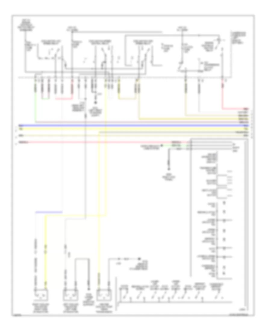
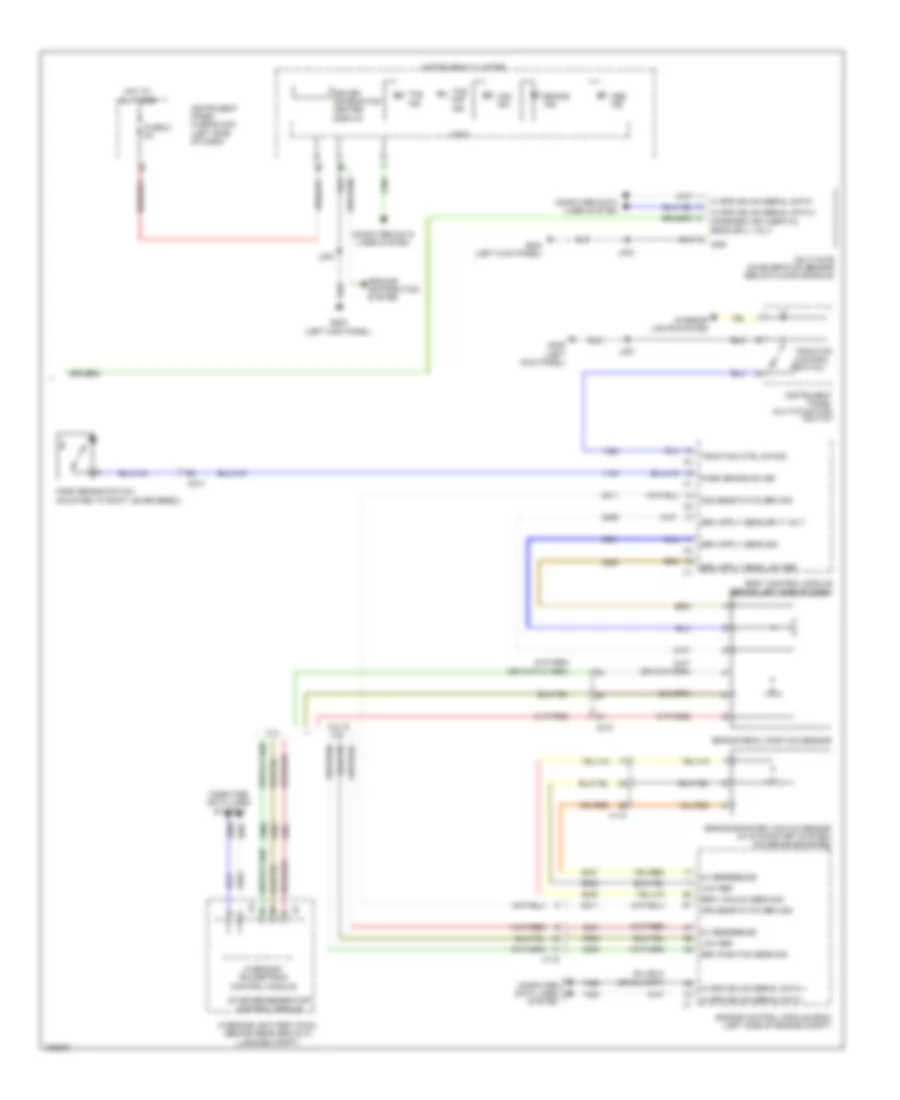
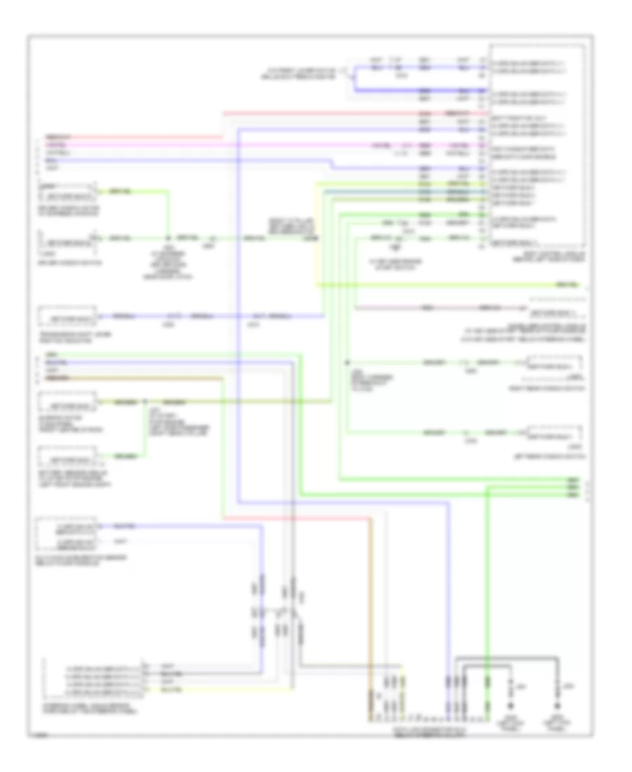
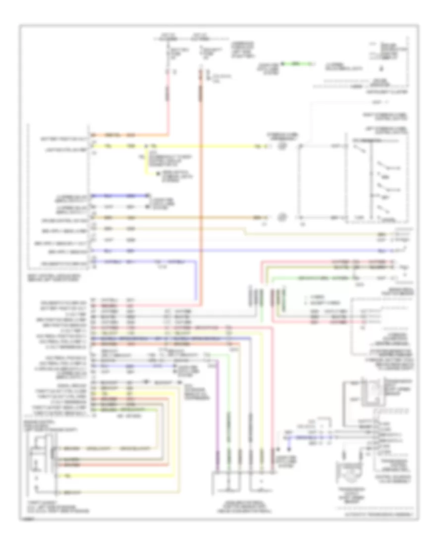
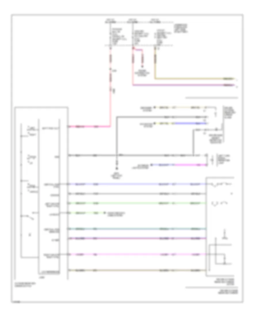
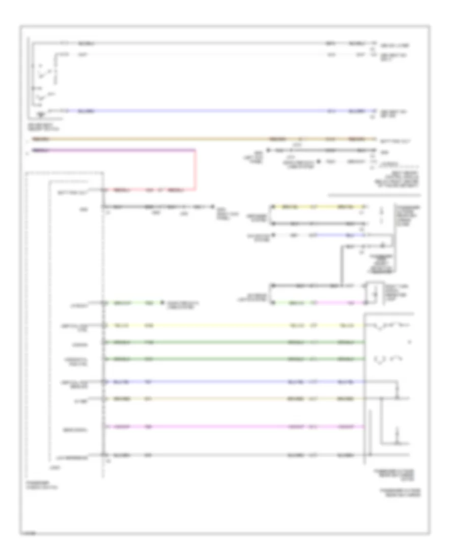
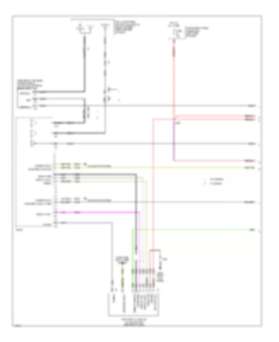
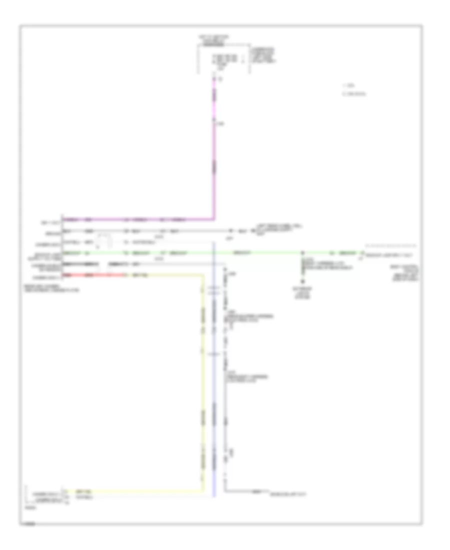
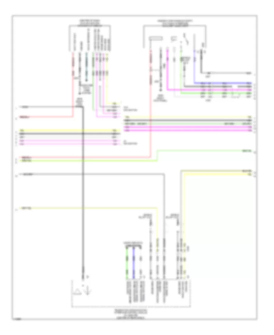
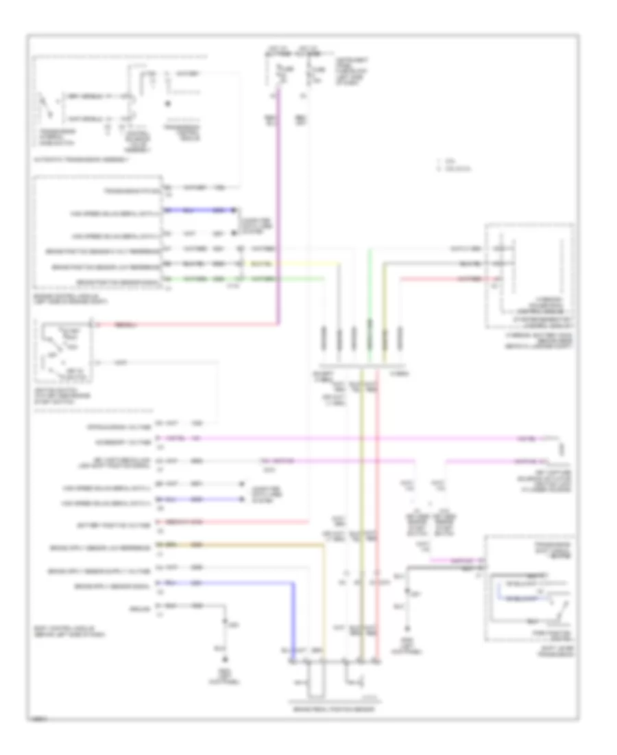
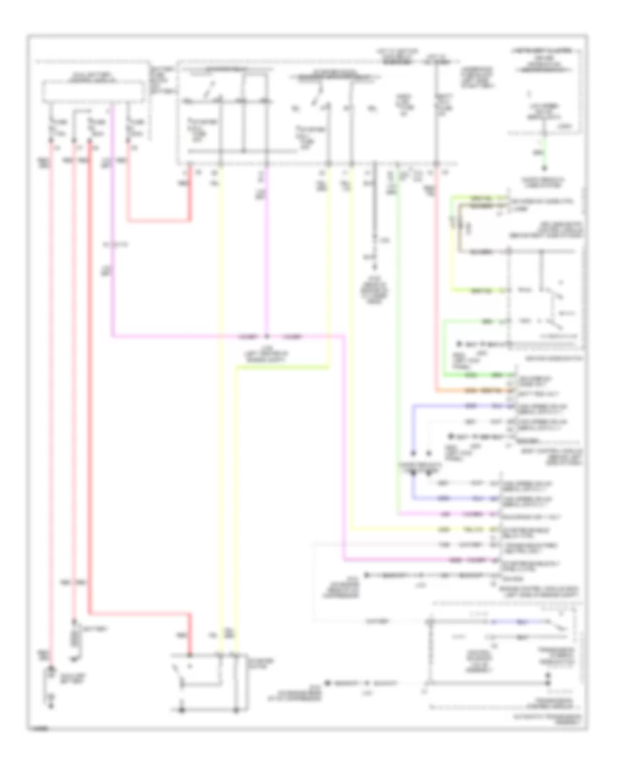
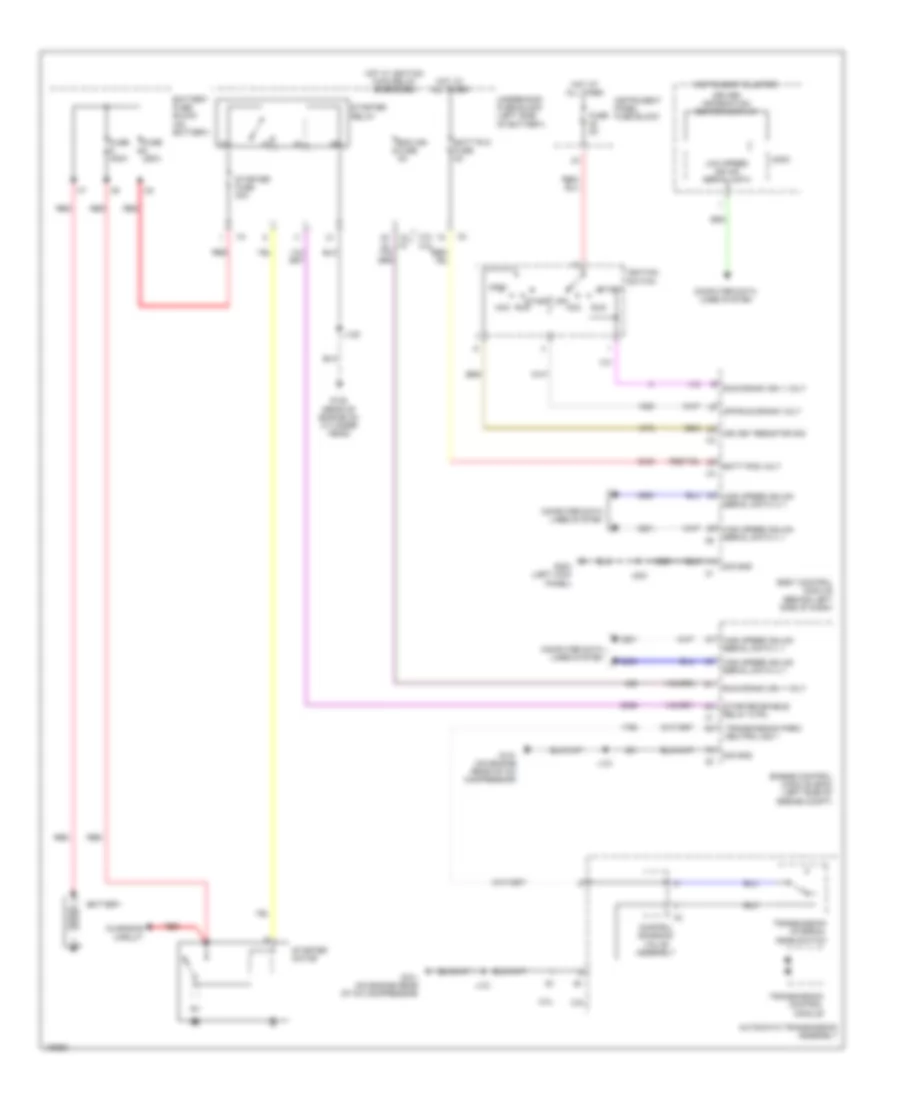
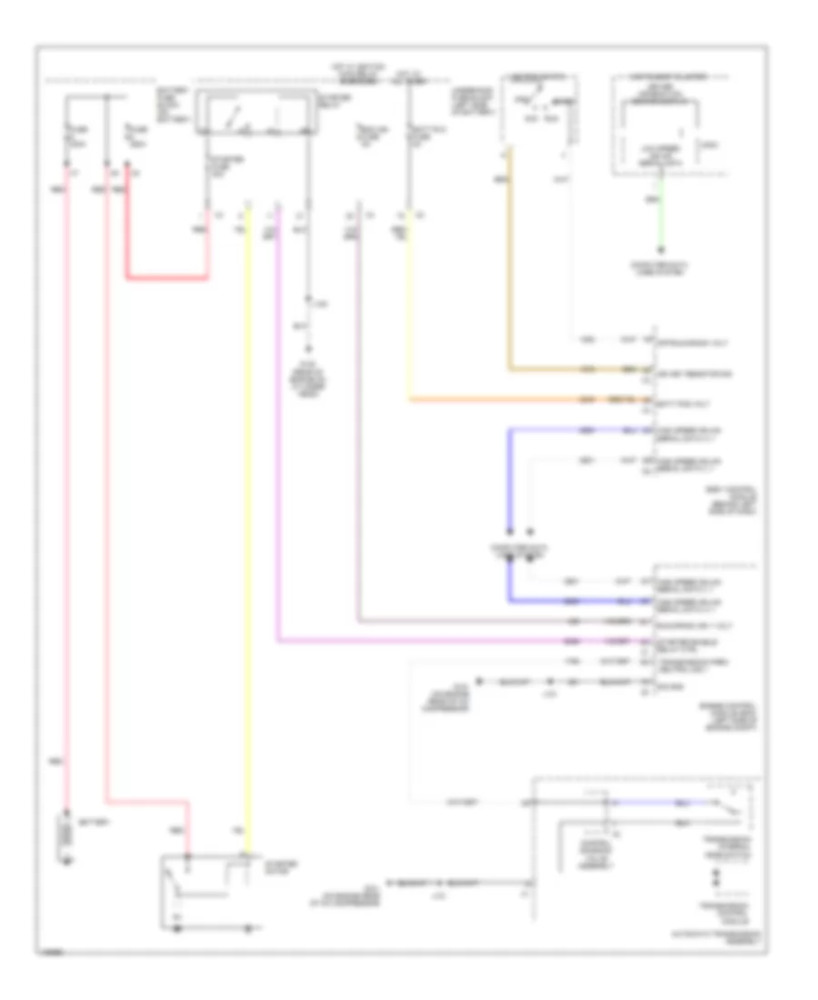
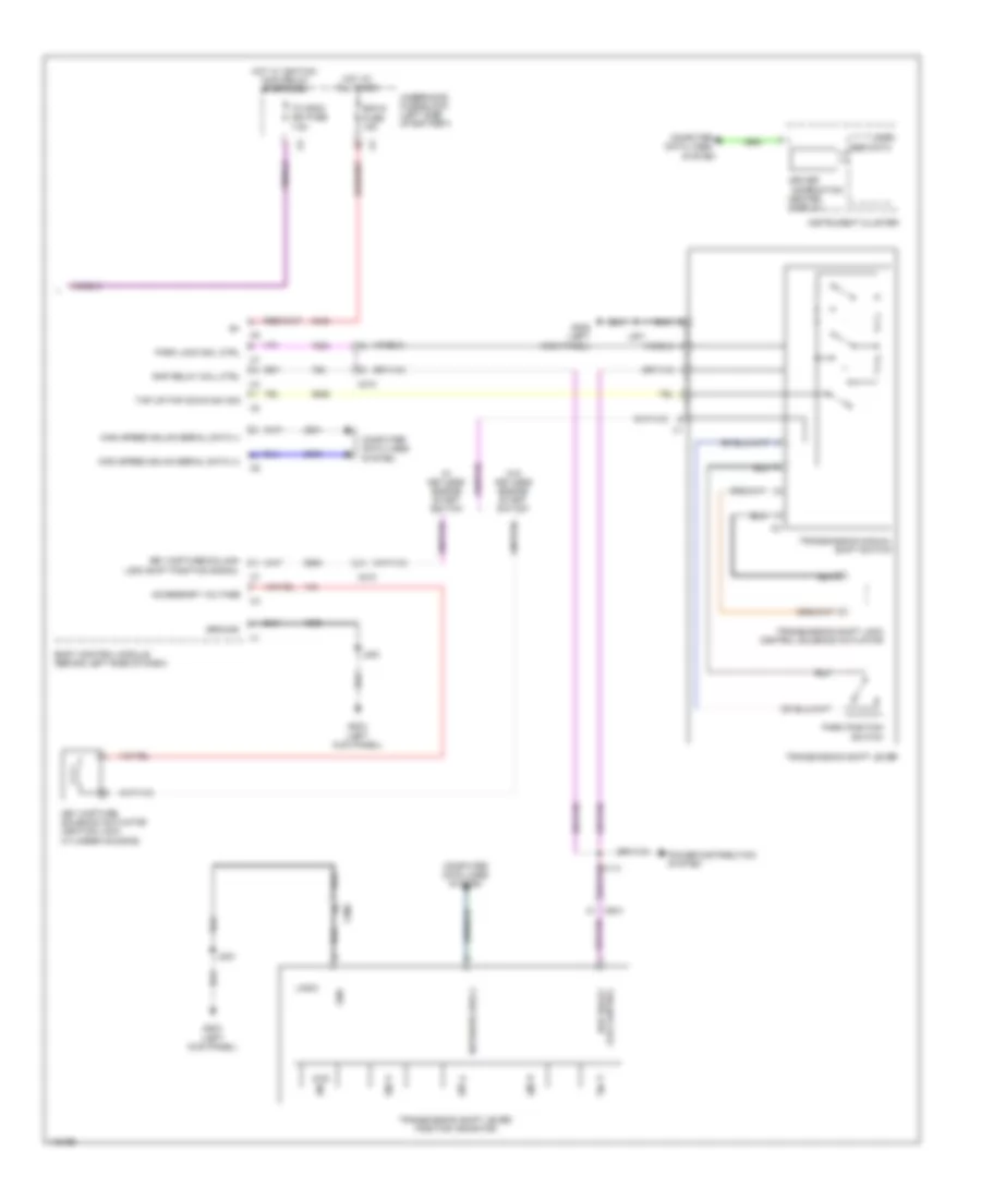
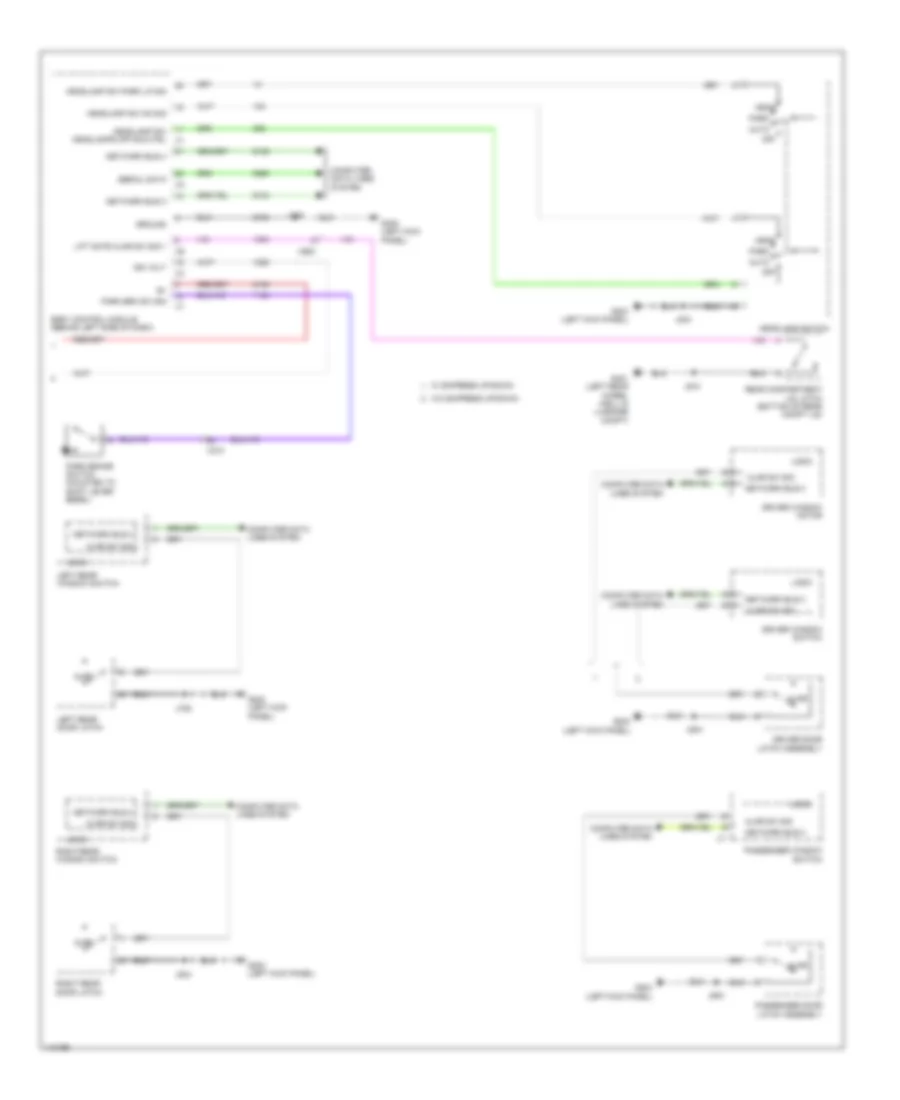
Automatic A/C Wiring Diagram (1 of 4) for Chevrolet Malibu LT 2014
 https://portal-diagnostov.com/license.html
Automotive Electricians Portal FZCO
Automotive Electricians Portal FZCO
https://portal-diagnostov.com/license.html
https://portal-diagnostov.com/license.html
Automotive Electricians Portal FZCO
Automotive Electricians Portal FZCO
List of elements for Automatic A/C Wiring Diagram (1 of 4) for Chevrolet Malibu LT 2014:
- (left kick panel) g203
- 5-volt ref
- A/c compressor solenoid valve (rear of a/c compressor)
- Batt pos voltage
- Battery positive voltage
- Blower motor (bottom of hvac casing)
- Blower motor control module (behind right center of dash)
- Blower mtr spd ctrl
- Blwr mtr spd ctrl
- Blwr mtr sply volt
- Computer data lines system
- Data serial gmlan low spd
- Defogger system
- Driver information center display
- Ele variable displacement ctrl
- Ele variable displacement sply
- Front blwr mtr rtn
- Fuse 11 40a
- Fuse 17 10a
- Fuse 19 10a
- G302 (right kick panel)
- Gnd
- Ground
- Hot at all times
- Hot w/ ignition main relay energized
- Humidity sens sig
- Humidity temp sens sig
- Hvac control module (center of dash)
- Inside air temp sens low ref
- Inside air temp sens sig
- Instrument cluster
- Instrument panel fuse block (left side of dash)
- Ip rc ign fuse (2.0l) 5a
- J203
- J204
- J206
- Linear interconnect network bus 9
- Logic
- Low speed gmlan serial data
- Power distribution system
- Rear defog rly ctrl
- Red
- Run/crank ignition 1 volt
- Temp sens low ref
- Twilight sentinel delay signal
- Underhood fuse block (left side of battery)
- Windscreen temp sens sig
- Windshield temperature & inside moisture sensor (top center of windshield)
- X115
- X210
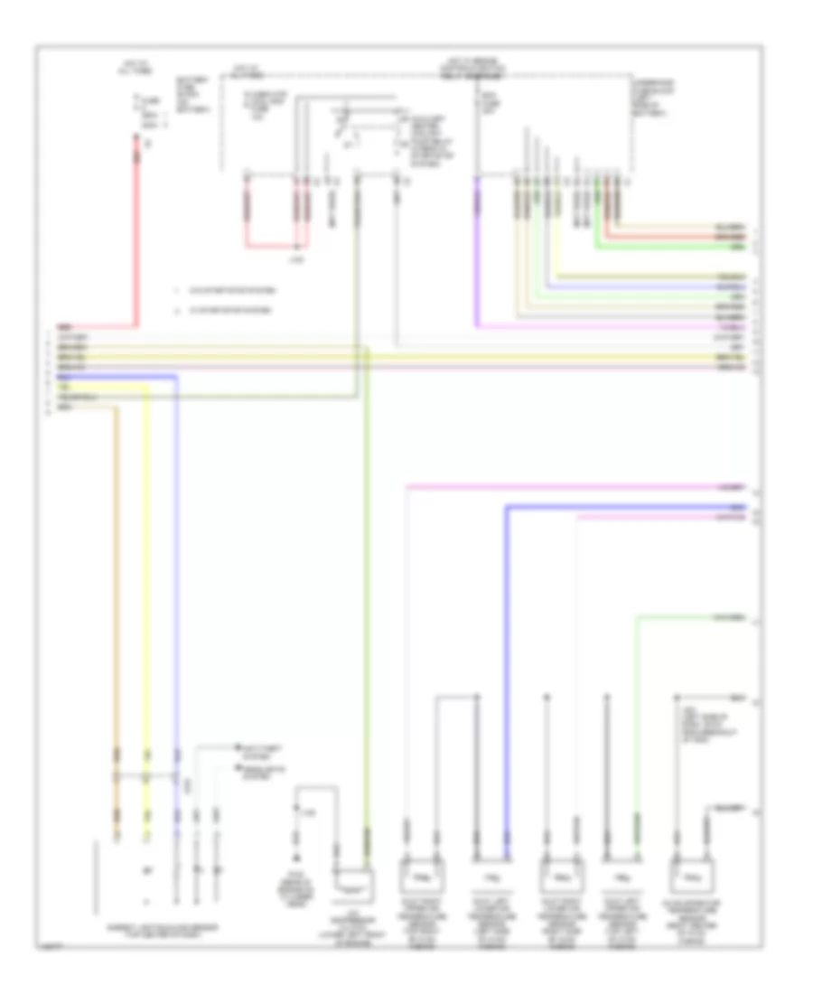
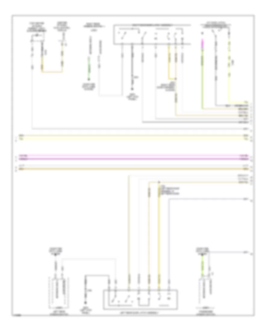
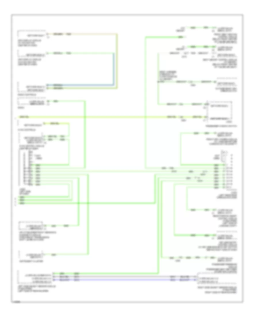
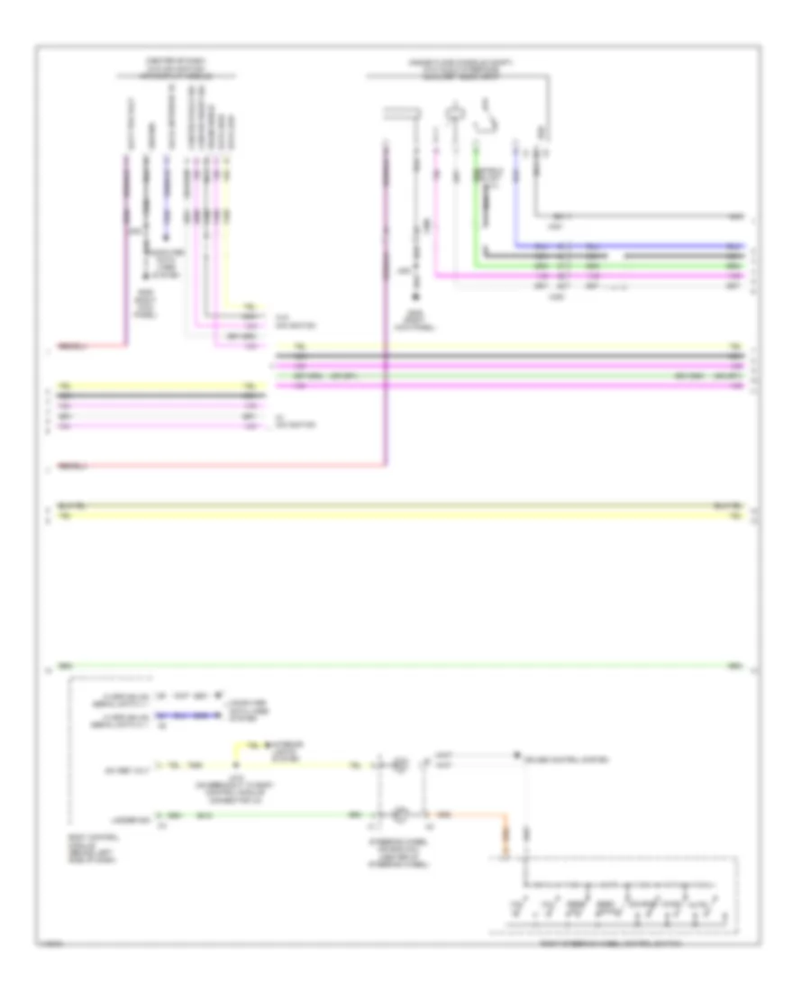
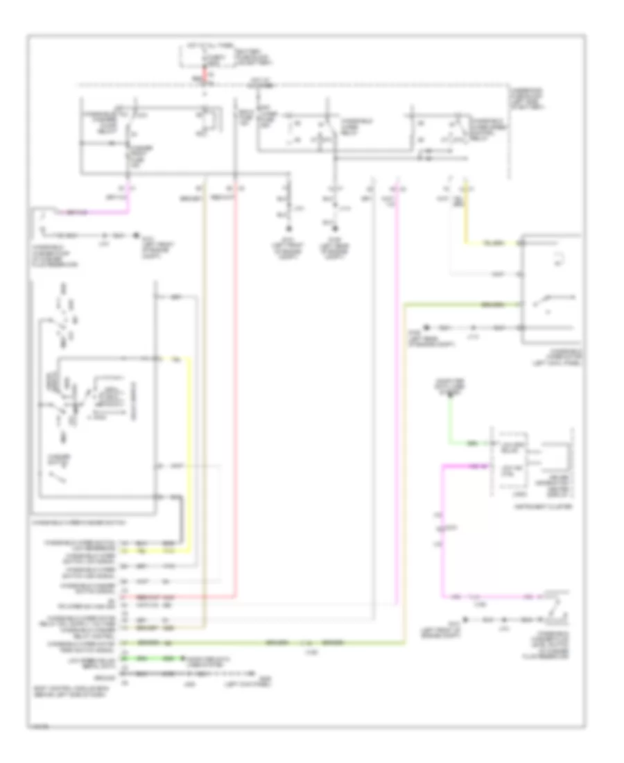
Automatic A/C Wiring Diagram (2 of 4) for Chevrolet Malibu LT 2014
List of elements for Automatic A/C Wiring Diagram (2 of 4) for Chevrolet Malibu LT 2014:
- A/c
- A/c clutch fuse 10a
- A/c-on ind
- A/c-on switch
- Auto ind
- Auto switch
- Blower switch
- Bus 9
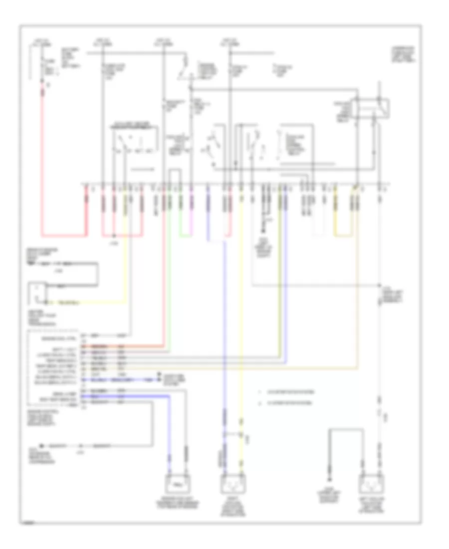
- Cfan k1 fuse 30a
- Cfan k2 fuse 30a
- Compressor clutch relay
- Computer data lines system
- Cooling fan high speed relay
- Cooling fan low speed relay
- Cooling fan speed control relay
- Defrost air outlet ind
- Defrost air outlet switch
- Driver information center display
- Engine controls ignition relay
- Fan relay a fuse 10a
- G101 (left front of engine compt)
- G106 (upper left radiator support)
- G122 (rear of engine on cylinder head)
- G205 (right kick panel)
- Gnd
- Heater coolant pump (near transmission)
- Hot at all times
- Hot w/ engine controls ignition relay energized
- Hvac controls
- J101
- J118 (near left headlamp assembly)
- J120
- Left cooling fan motor (left side of radiator)
- Logic
- Lower & upper air outlet ind
- Lower air outlet ind
- Lower air outlet switch
- Recirculation ind
- Recirculation switch
- Red
- Right cooling fan motor (right side of radiator)
- Sync ind
- Sync switch
- Temperature control switch
- Underhood fuse block (left side of battery)
- Upper air outlet ind
- Upper air outlet switch
- Ventilation fan switch
- Windshield defrost ind
- Windshield defrost switch
- X116
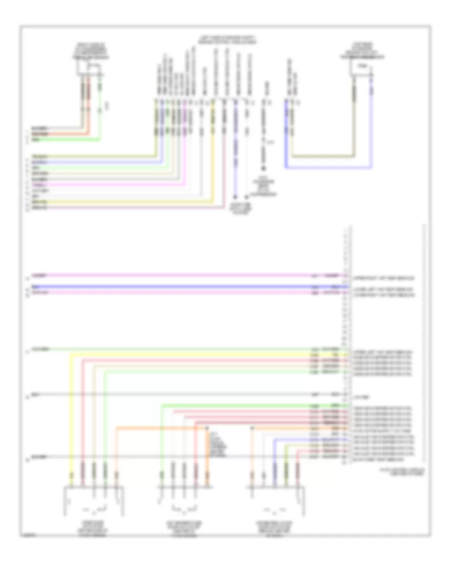
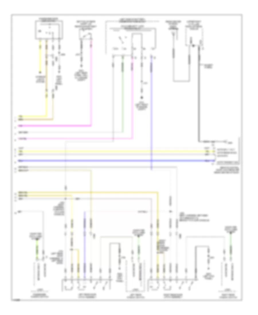
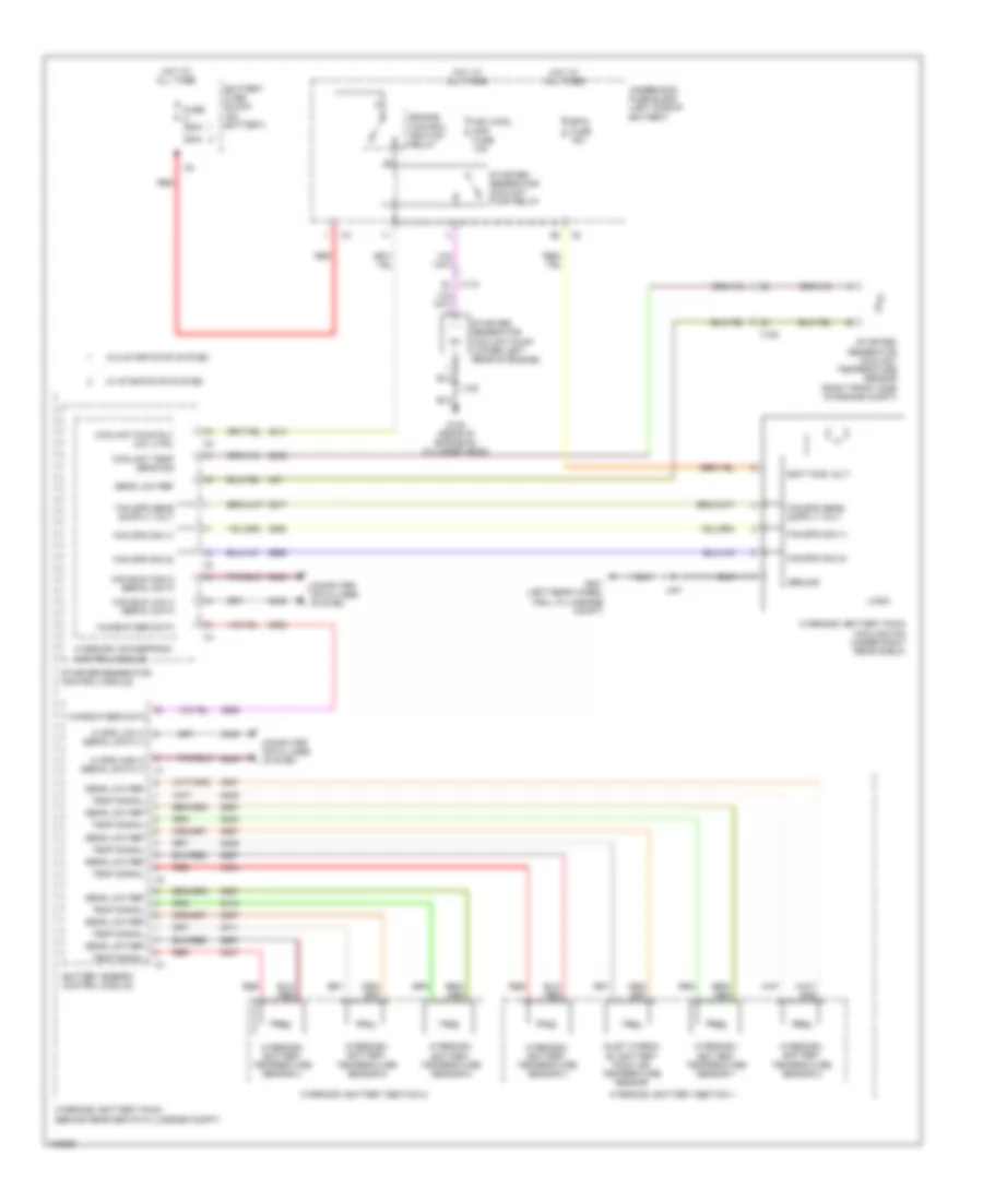
Automatic A/C Wiring Diagram (3 of 4) for Chevrolet Malibu LT 2014
List of elements for Automatic A/C Wiring Diagram (3 of 4) for Chevrolet Malibu LT 2014:
- (not used)
- 200a
- A/c compressor clutch (lower left front of engine)
- A/c evaporator temperature sensor (right center of hvac casing)
- Ambient light/sunload sensor (top center of dash)
- Anti-theft system
- Auxiliary
- Battery fuse block (on battery)
- Cabin htr cool pmp fuse 10a
- Duct left lower air temperature sensor (left side of hvac casing)
- Duct left upper air temperature sensor (top left of hvac casing)
- Duct right lower air temperature sensor (right side of hvac casing)
- Duct right upper air temperature sensor (top right of hvac casing)
- Ecm fuse 20a
- Fuse 250a
- G122 (rear of engine on cylinder head)
- Headlights system
- Heater coolant pump relay (hybrid w/ start/stop system)
- Hot at all times
- Hot w/ engine controls ignition relay energized
- J120
- J123
- J231 (left side of dash, 49 cm from breakout of x500)
- Red
- Underhood fuse block (left side of battery)
- W/ start/stop system
- W/o start/stop system
- X215
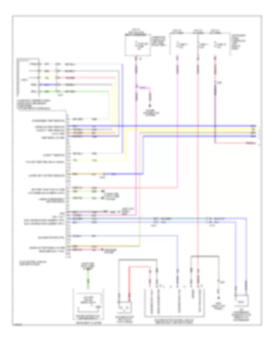
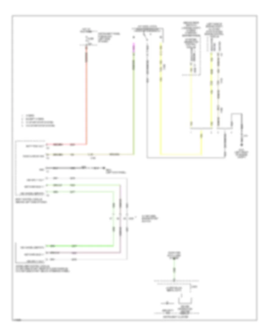
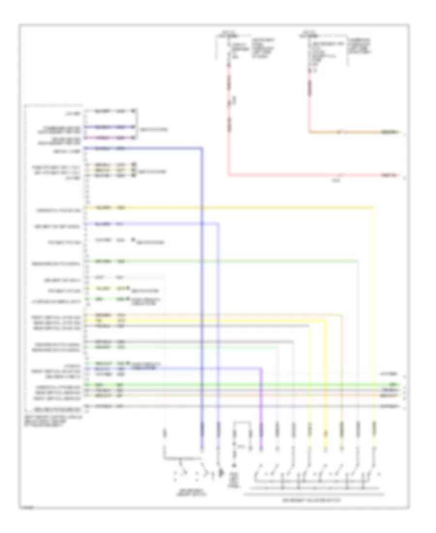
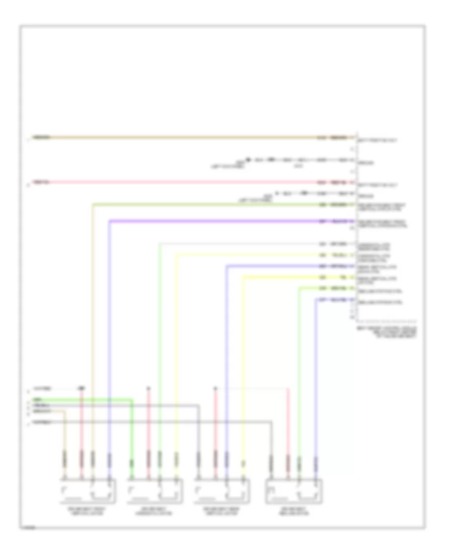
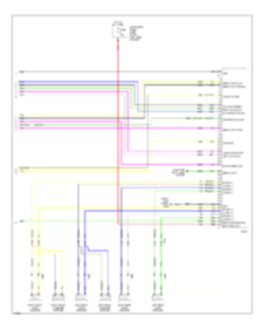
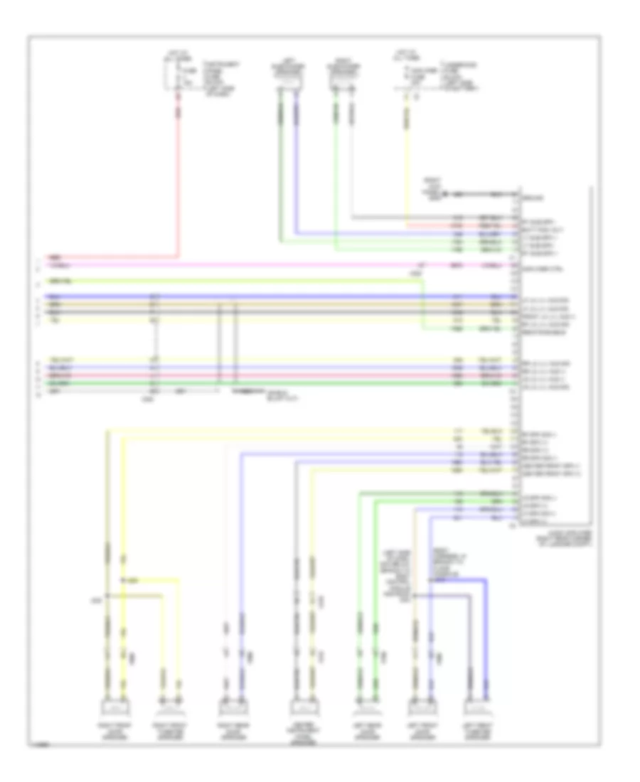
Automatic A/C Wiring Diagram (4 of 4) for Chevrolet Malibu LT 2014
List of elements for Automatic A/C Wiring Diagram (4 of 4) for Chevrolet Malibu LT 2014:
- (left side of engine compt) engine control module (ecm)
- (right side of a/c condenser) a/c refrigerant pressure sensor
- (top rear of engine) engine coolant temperature sensor
- 5v volt ref
- A/c low ref
- A/c press sens sig
- Air inlet dr stepper mtr ctrl
- Air recirculation door actuator (behind center of dash)
- Air temperature door actuator (center of hvac casing)
- Cmprsr clutch rly ctrl
- Computer data lines system
- Cooling fan relay ctrl
- Eng cool ctrl
- Eng temp sens sig
- Evap core temp sens sig
- G121 (on engine rear of a/c compressor)
- Gmlan serial data (+)
- Gmlan serial data (-)
- Hvac control module (center of dash)
- J121
- J217 (hvac module harness, center of dash)
- Low ref
- Lower left air temp sens sig
- Lower right air temp sens sig
- Main relay fused sply
- Mode door actuator (driver side of hvac casing)
- Mode dr stepper motor ctrl
- Sens lo ref
- Sig gnd
- Temp dr stepper motor ctrl
- Temp sens low ref 2
- Temp sens sig 2
- Upper left air temp sens sig
- Upper right air temp sens sig
- X117
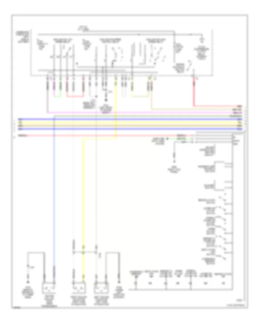
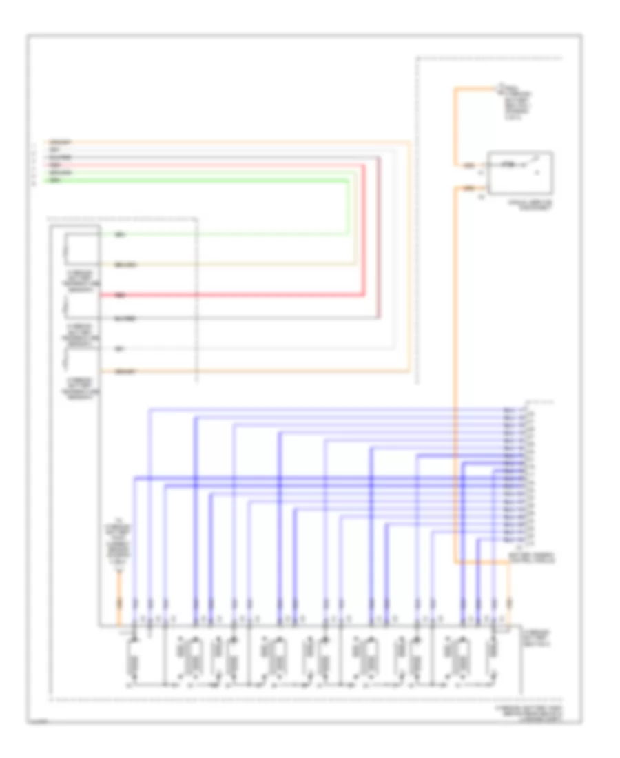
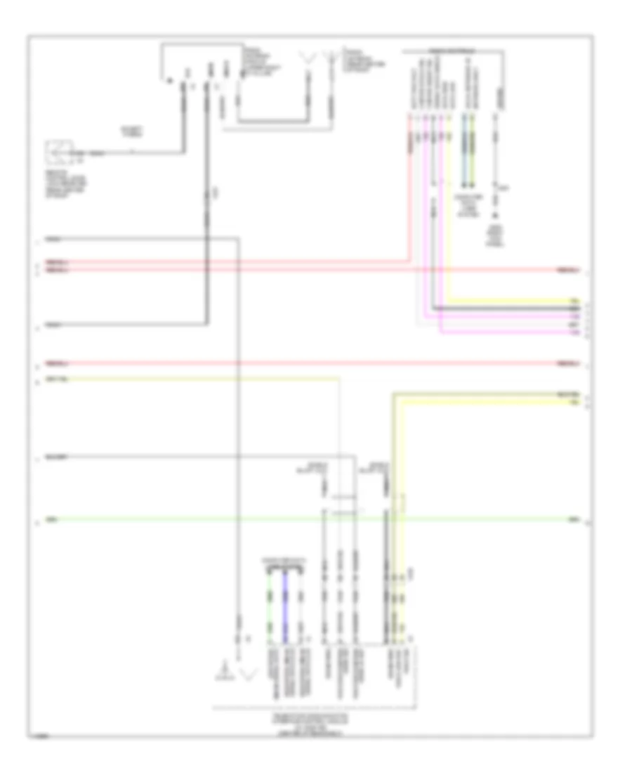
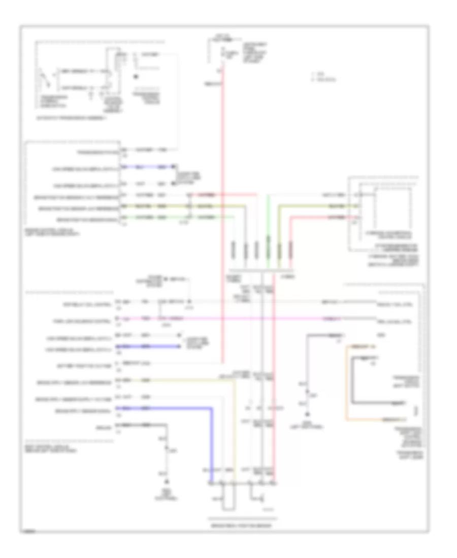
Manual A/C Wiring Diagram (1 of 4) for Chevrolet Malibu LT 2014
List of elements for Manual A/C Wiring Diagram (1 of 4) for Chevrolet Malibu LT 2014:
- (left kick panel) g203
- 5-volt ref
- A/c compressor solenoid valve (rear of a/c compressor)
- Batt pos voltage
- Battery positive voltage
- Blower motor (bottom of hvac casing)
- Blower motor control module (behind right center of dash)
- Blower mtr spd ctrl
- Blwr mtr spd ctrl
- Blwr mtr sply volt
- Computer data lines system
- Defogger system
- Distribution
- Driver information center display
- Ele variable displacement ctrl
- Ele variable displacement sply
- Front blwr mtr rtn
- Fuse 11 40a
- Fuse 17 10a
- Fuse 19 10a
- G302 (right kick panel)
- Gnd
- Ground
- Hot at all times
- Hot w/ ignition main relay energized
- Humidity sens sig
- Humidity temp sens sig
- Hvac control module (center of dash)
- Ign 1 volt
- Inside air temp sens low ref
- Inside air temp sens sig
- Instrument cluster
- Instrument panel fuse block (left side of dash)
- Ip rc ign fuse 5a
- J203
- J204
- J206
- Linear interconnect network bus 9
- Logic
- Low spd gmlan serial data
- Low speed gmlan serial data
- Lower left air temp sens sig
- Power
- Rear defog rly ctrl
- Red
- System
- Temp sens low ref
- Twilight sentinel delay signal
- Underhood fuse block (left side of battery)
- Windscreen temp sens sig
- Windshield temperature & inside moisture sensor (if equipped) (top center of windshield)
- X115
- X210
- X216
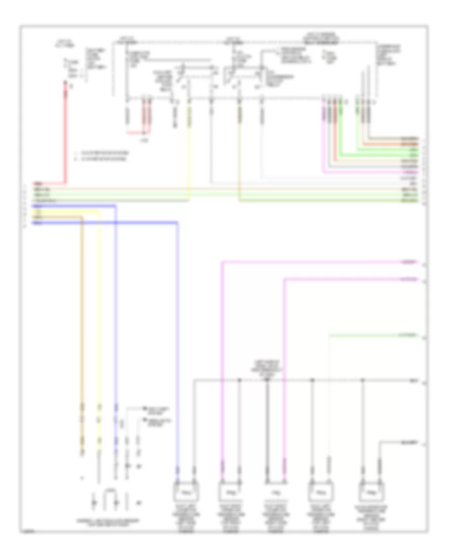
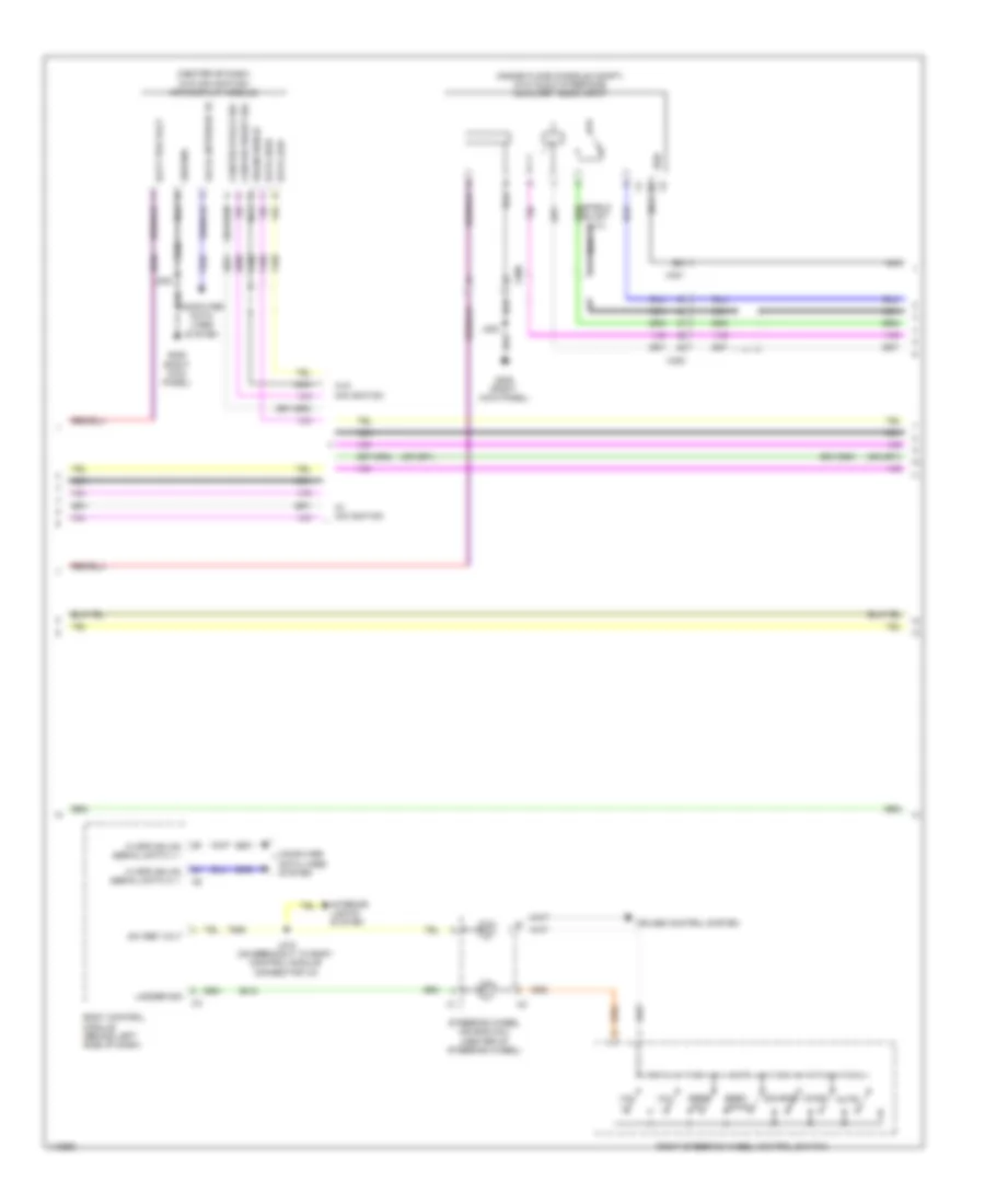
Manual A/C Wiring Diagram (2 of 4) for Chevrolet Malibu LT 2014
List of elements for Manual A/C Wiring Diagram (2 of 4) for Chevrolet Malibu LT 2014:
- Blower switch
- Bus 9
- Computer data lines system
- Cool fan k1 fuse 30a
- Cool fan k2 fuse 30a
- Cooling fan high speed relay
- Cooling fan low speed relay
- Cooling fan speed control relay
- Defrost & lower air outlet ind
- Defrost & lower air outlet switch
- Driver information center display
- Engine controls ignition relay
- Fan relay a fuse 10a
- G101 (left front of engine compt)
- G106 (upper left radiator support)
- G122 (rear of engine on cylinder head)
- G205 (right kick panel)
- Gnd
- Heater coolant pump (near transmission)
- Hot at all times
- Hvac controls
- J101
- J118 (near left headlamp assembly)
- J120
- Left cooling fan motor (left side of radiator)
- Logic
- Lower air outlet ind
- Lower air outlet switch
- Recirculation ind
- Recirculation switch
- Red
- Right cooling fan motor (right side of radiator)
- Temperature control switch
- To a/c compressor clutch relay (diagram 3 of 4)
- Underhood fuse block (left side of battery)
- Upper & lower air outlet ind
- Upper & lower air outlet switch
- Upper outlet ind
- Upper outlet switch
- Ventilating fan ind
- Ventilating fan switch
- Windshield defrost ind
- Windshield defrost switch
- X116
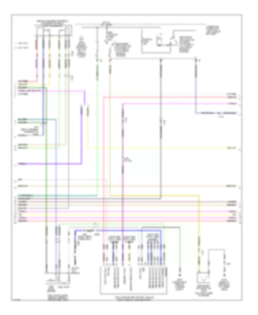
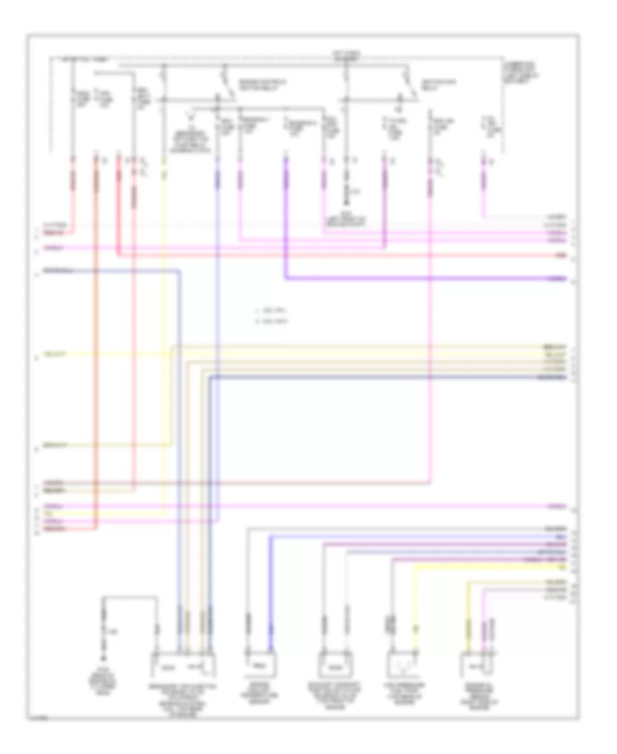
Manual A/C Wiring Diagram (3 of 4) for Chevrolet Malibu LT 2014
List of elements for Manual A/C Wiring Diagram (3 of 4) for Chevrolet Malibu LT 2014:
- (left side of dash, 49 cm from breakout of x500) j231
- (not used)
- 200a
- A/c clutch fuse 10a
- A/c compressor clutch relay
- A/c evaporator temperature sensor (right center of hvac casing)
- Ambient light/sunload sensor (top center of dash)
- Anti-theft system
- Auxiliary heater coolant pump relay
- Battery fuse block (on battery)
- Cabin htr cool pmp fuse 15a
- Duct left lower air temperature sensor (left side of hvac casing)
- Duct left upper air temperature sensor (top left of hvac casing)
- Duct right lower air temperature sensor (right side of hvac casing)
- Duct right upper air temperature sensor (top right of hvac casing)
- Ecm fuse 20a
- From engine controls ignition relay (diagram 2 of 4)
- Fuse 250a
- Headlights system
- Hot at all times
- Hot w/ engine controls ignition relay energized
- J123
- Logic
- Red
- Underhood fuse block (left side of battery)
- W/ start/stop system
- W/o start/stop system
- X215
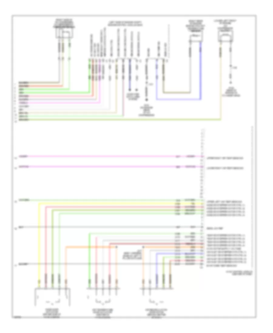
Manual A/C Wiring Diagram (4 of 4) for Chevrolet Malibu LT 2014
List of elements for Manual A/C Wiring Diagram (4 of 4) for Chevrolet Malibu LT 2014:
- (left side of engine compt) engine control module (ecm)
- (lower left front of engine) a/c compressor clutch
- (right rear of engine) engine coolant temperature sensor
- (right side of a/c condenser) a/c refrigerant pressure sensor
- 5v volt ref
- A/c low ref
- A/c press sens sig
- Air inlet dr stepper mtr ctrl (1)
- Air inlet dr stepper mtr ctrl (2)
- Air inlet dr stepper mtr ctrl (3)
- Air inlet dr stepper mtr ctrl (4)
- Air recirculation door motor (behind center of dash)
- Air temperature door actuator (center of hvac casing)
- Cmprsr clutch rly ctrl
- Computer data lines system
- Cooling fan relay ctrl
- Eng cool ctrl
- Eng temp sig
- Evap core temp sens sig
- G121 (on engine rear of a/c compressor)
- G122 (rear of engine on cylinder head)
- Gmlan serial data (+)
- Gmlan serial data (-)
- Hvac control module (center of dash)
- J120
- J121
- J217 (body harness, base of left "a" pillar on floor)
- Lower right air temp sens sig
- Main relay fused sply
- Mode door actuator (driver side of hvac casing)
- Mode dr stepper motor ctrl (1)
- Mode dr stepper motor ctrl (2)
- Mode dr stepper motor ctrl (3)
- Mode dr stepper motor ctrl (4)
- Sens lo ref
- Sens low ref
- Sig gnd
- Temp dr stepper motor ctrl (1)
- Temp dr stepper motor ctrl (2)
- Temp dr stepper motor ctrl (3)
- Temp dr stepper motor ctrl (4)
- Upper left air temp sens sig
- Upper right air temp sens sig
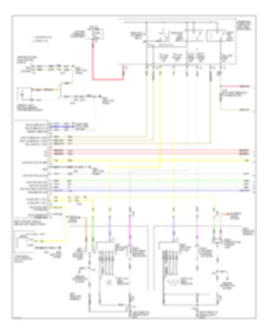
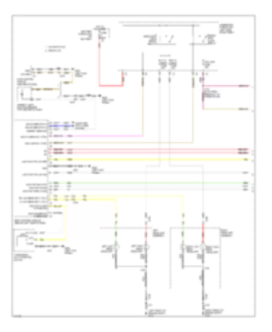
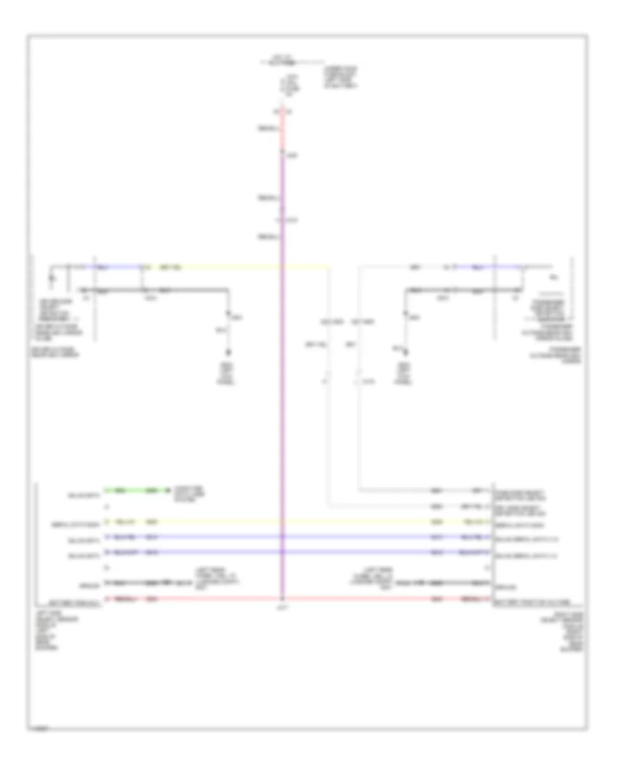
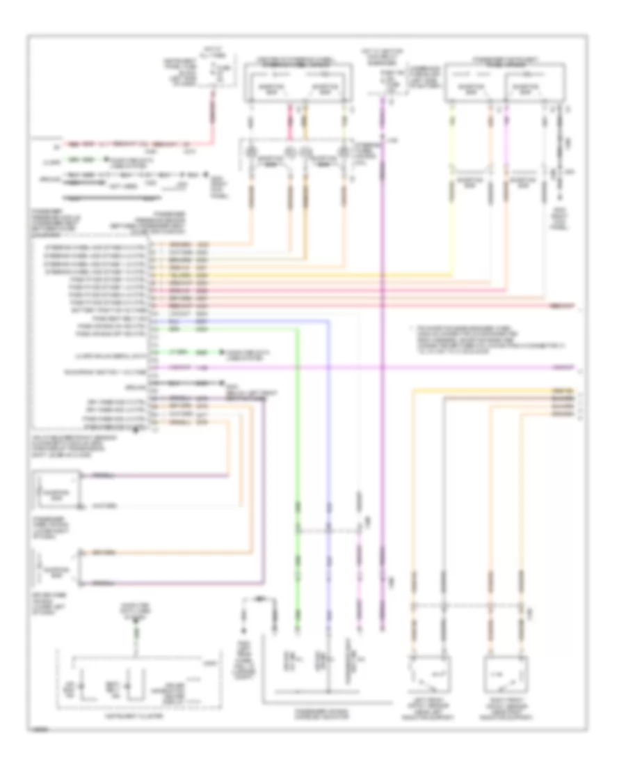
ANTI-LOCK BRAKES
Anti-lock Brakes Wiring Diagram (1 of 2) for Chevrolet Malibu LT 2014
List of elements for Anti-lock Brakes Wiring Diagram (1 of 2) for Chevrolet Malibu LT 2014:
- 5 volt reference
- Abs pump fuse 60a
- Abs valve fuse 25a
- Battery positive voltage
- Brake booster pump motor (mounted to the frame, forward of right front axle shaft)
- Brake booster pump motor relay (2.4l) (mounted to the frame, forward of right front axle shaft)
- Brake booster vacuum sensor (w/o stop/start system) (on brake booster)
- Brake fluid level switch (top of the brake fluid reservoir)
- Brake pressure modulator (left rear engine compt near master cylinder)
- Brake vacuum sensor signal
- Brake vacuum switch signal
- Brk vac pump fuse 20a
- Combined veh inertial
- Communication enable
- Computer data lines system
- Computer data lines systems
- Electronic brake control module (near brake master cylinder)
- Fr wss sig
- G102 (right front of engine compt)
- G110 (left front of engine compt)
- G203 (left kick panel)
- Gnd
- Ground
- Hi spd gmlan serial data +
- Hi spd gmlan serial data + sens sply volt
- Hi spd gmlan serial data -
- Hi spd gmln serial data (+)
- Hi spd gmln serial data (-)
- Hot at all times
- J102
- J110
- J203
- J304
- Left front wheel speed sensor (wss) (at left front wheel)
- Left rear wheel speed sensor (wss) (at left rear wheel)
- Level sensor signal
- Lf wss low ref
- Low reference
- Lr wss low ref
- Lr wss signal
- Lt wss sig
- Red
- Rf wss low ref
- Rf wss sig
- Right front wheel speed sensor (wss) (at right front wheel)
- Right rear wheel speed sensor (wss) (at right rear wheel)
- Rr wss low ref
- Sens sply volt
- Serial data
- Steering wheel angle sensor (forward of the steering wheel)
- Underhood fuse block (left side of battery)
- X150
- X210
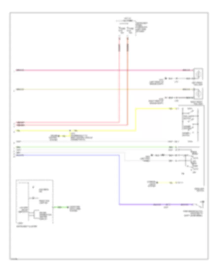
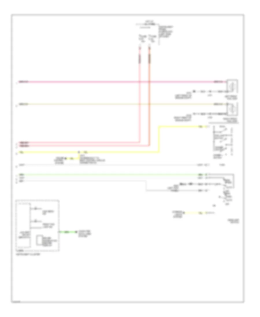
Anti-lock Brakes Wiring Diagram (2 of 2) for Chevrolet Malibu LT 2014
List of elements for Anti-lock Brakes Wiring Diagram (2 of 2) for Chevrolet Malibu LT 2014:
- 2.0l & 2.5l
- 2.4l
- 5v reference
- Abs ind
- Body control module (behind left side of dash)
- Brake booster vacuum sensor (w/ stop/start system) (on brake booster)
- Brake ind
- Brake pedal position sensor
- Brk position sens sig
- Brk vacuum sens sig
- Combined veh inertial sens sply volt
- Computer data lines system
- Cruise/etc/tcc brk sig
- Driver information center display
- Engine control module (ecm) (left side of engine compt)
- Fuse 21 5a
- G203 (left kick panel)
- G305 (left kick panel)
- Gnd
- Ground distribution system
- Hi spd gmlan serial data +
- Hi spd gmlan serial data -
- Hot at all times
- Hybrid/ev battery pack (behind rear seats in luggage compt)
- Hybrid/ev powertrain control module
- Instrument cluster
- Instrument panel fuse block (left side of dash)
- Instrument panel multi-function switch
- Interior lights system
- J201
- J203
- J304
- Logic
- Low ref
- Multi-axis acceleration sensor (below floor console)
- Park brake sw sig
- Park brake switch (mounted to shift lever bezel)
- Starter/generator control module
- Tcs ind
- Tcs off ind
- Traction control switch
- Traction ctrl sw sig
- Vdc ind
- X115
- X210
ANTI-THEFT
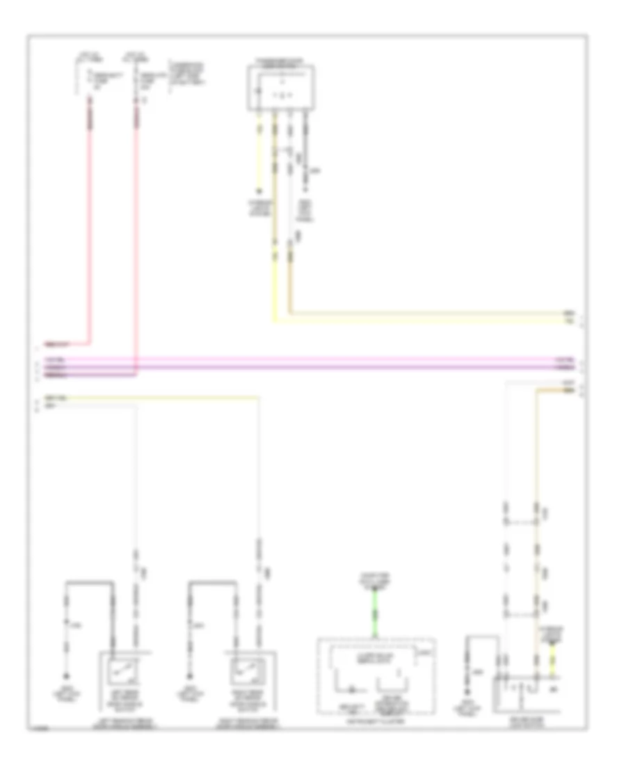
Forced Entry Wiring Diagram, with Passive Keyless Entry (1 of 4) for Chevrolet Malibu LT 2014
List of elements for Forced Entry Wiring Diagram, with Passive Keyless Entry (1 of 4) for Chevrolet Malibu LT 2014:
- (behind center of dash) instrument panel compartment keyless entry antenna
- (in luggage compt) rear compartment keyless entry antenna
- Accessory volt
- Ant lo ref (1)
- Ant lo ref (2)
- Ant lo ref (5)
- Ant sig (1)
- Ant sig (2)
- Ant sig (5)
- Batt pos volt
- Center console rear keyless entry antenna
- Computer data lines system
- Driver door handle keyless entry antenna
- Driver exterior door handle assembly
- Driver exterior door handle switch
- Drv dr unlatch sw sig
- G203 (left kick panel)
- G302 (right kick panel)
- Gnd
- Ignition mode switch
- J302
- J504
- J604
- Keyless entry control module (behind right side of dash)
- Low ref
- Low ref (6)
- Low ref (7)
- Low ref (8
- Lr dr unlatch sw sig
- Pass dr unlatch sw sig
- Passenger door handle keyless entry antenna
- Passenger exterior door handle assembly
- Passenger exterior door handle switch
- Rear fascia keyless entry antenna (below luggage compt opening)
- Rr dr unlatch sw sig
- Run/crank ign 1 volt
- Serial data
- Sig (6)
- Sig (7)
- Sig (8)
- Sw mode ctrl
- X210
- X300
- X500
- X600
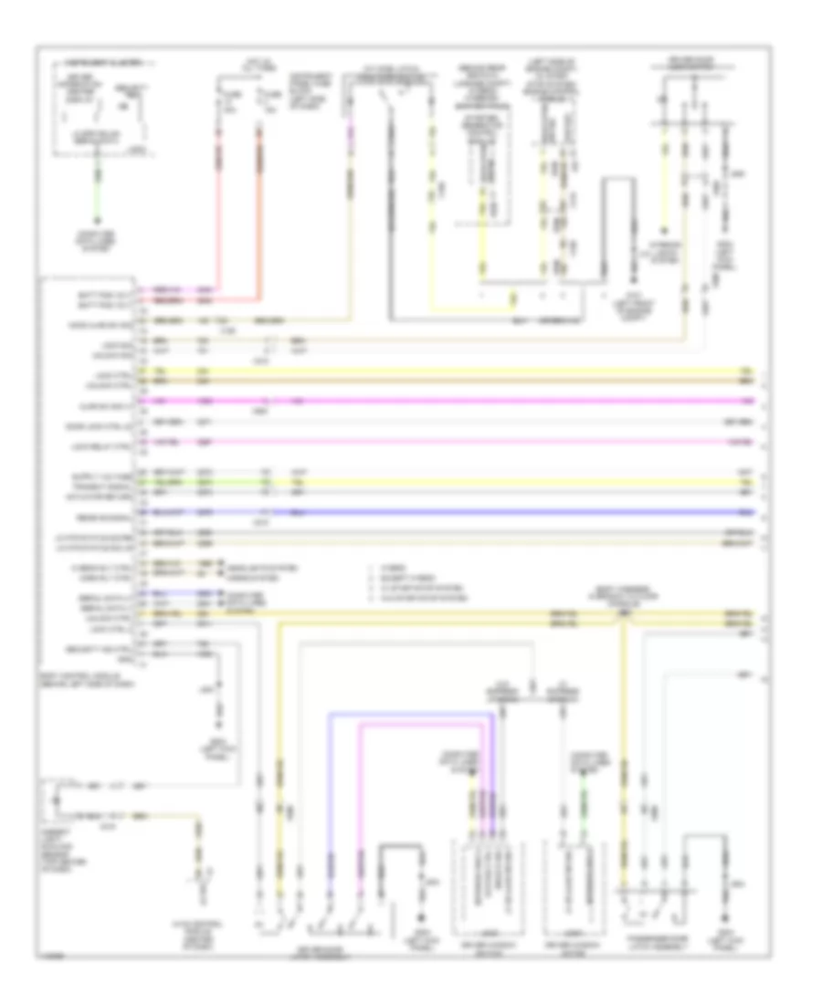
Forced Entry Wiring Diagram, with Passive Keyless Entry (2 of 4) for Chevrolet Malibu LT 2014
List of elements for Forced Entry Wiring Diagram, with Passive Keyless Entry (2 of 4) for Chevrolet Malibu LT 2014:
- Computer data lines system
- Driver door lock switch
- Driver information center (dic) display
- G203 (left kick panel)
- Hot at all times
- Instrument cluster
- Interior lights system
- J506
- J606
- J706
- J804
- Left rear exterior door handle assembly
- Left rear exterior door handle switch
- Lo spd gmlan
- Logic
- Passenger door lock switch
- Peps batt fuse 5a
- Peps mtr fuse 30a
- Right rear exterior door handle assembly
- Right rear exterior door handle switch
- Security ind
- Serial data
- Underhood fuse block (left side of battery)
- X210
- X500
- X505
- X600
- X605
- X700
- X800
Forced Entry Wiring Diagram, with Passive Keyless Entry (3 of 4) for Chevrolet Malibu LT 2014
List of elements for Forced Entry Wiring Diagram, with Passive Keyless Entry (3 of 4) for Chevrolet Malibu LT 2014:
- (at hood latch) hood ajar switch
- (center of dash) hvac control module
- (top center of dash) ambient light/ sunload sensor
- Ajar sw sig
- Computer data lines system
- G203 (left kick panel)
- J703 (left rear door harness, in left rear door)
- J706
- J803 (right rear door harness, in door)
- J804
- Left rear door latch assembly
- Left rear window switch
- Lo ref
- Logic
- Network bus 3
- Passenger window switch
- Right rear door latch assembly
- Right rear window switch
- X150
- X215
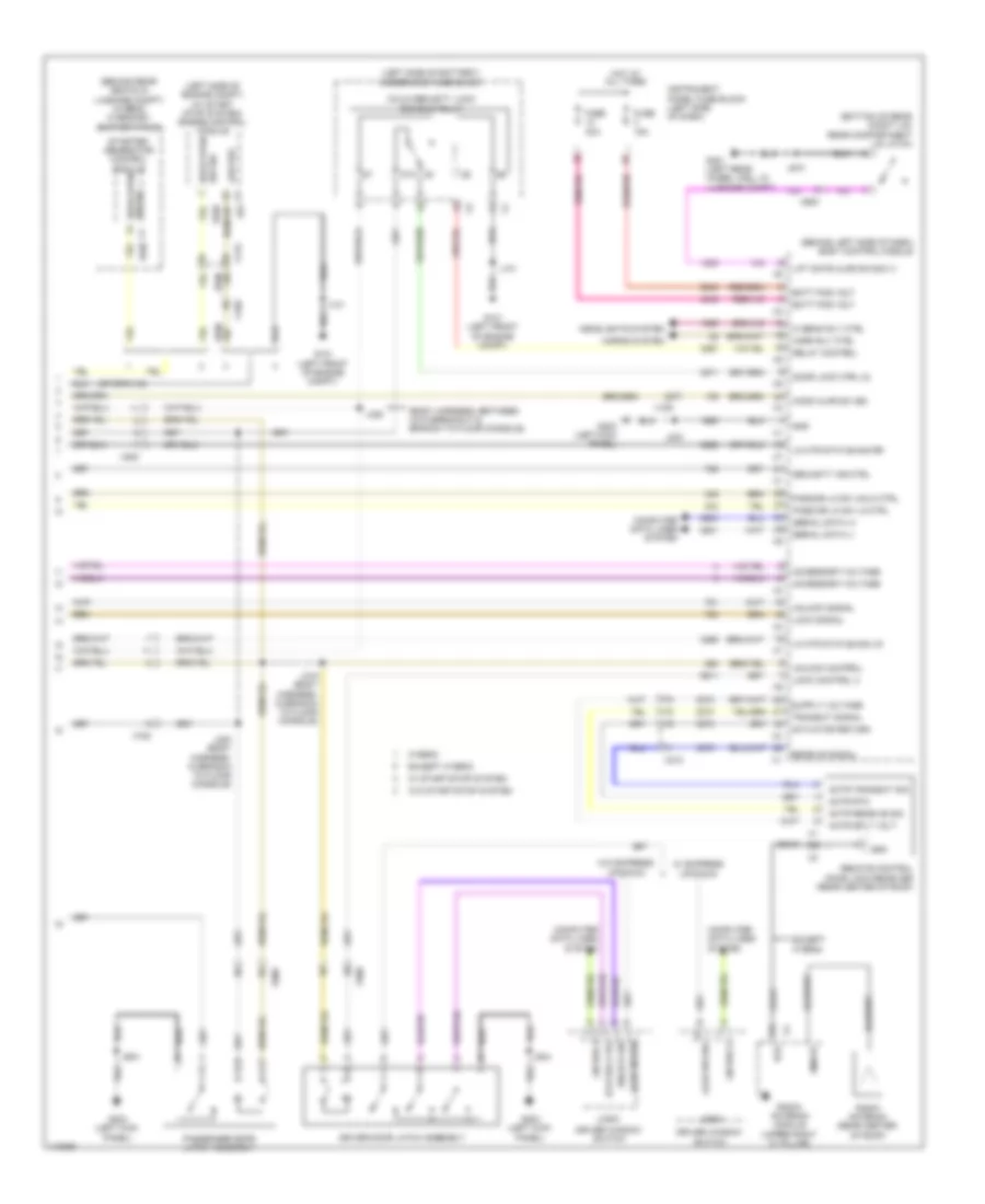
Forced Entry Wiring Diagram, with Passive Keyless Entry (4 of 4) for Chevrolet Malibu LT 2014
List of elements for Forced Entry Wiring Diagram, with Passive Keyless Entry (4 of 4) for Chevrolet Malibu LT 2014:
- (behind left side of dash) body control module
- (behind rear seats in luggage compt) (hybrid) hybrid/ev battery pack
- (body harness, between x310 breakout & branch to floor console)
- (bottom of rear compt lid) rear compartment lid latch
- (left side of battery) underhood fuse block
- (left side of engine compt) (w/ start stop system) engine control module
- 87a
- Accessory voltage
- Actr receive sig
- Actr rtn
- Actr sply volt
- Actr transmit sig
- Actuator return
- Ajar sw sig
- Batt pos volt
- Child security lock disable relay
- Coax
- Computer data lines system
- Door lock ctrl (2)
- Driver door latch assembly
- Driver window switch
- Except hybrid
- Fm/rfr
- Fuse 15a
- Fuse 30a
- G101 (left front of engine compt)
- G203 (left kick panel)
- G401 (left rear wheel well in luggage compt)
- Gnd
- Headlights system
- Hi beam rly ctrl
- Hood ajar sw sig
- Hood open sw sig
- Hood open sw sig x1
- Horn rly ctrl
- Horns system
- Hot at all times
- Hybrid
- Instrument panel fuse block (left side of dash)
- J101
- J203
- J319 (body harness, in branch to floor console)
- J320 (body harness, in branch to floor console)
- J328
- J504
- J604
- J910
- Lift gate ajar sw sig (1)
- Lin bus 3
- Lk mtr status sig lr
- Lk mtr status sig rr
- Lock control 2
- Lock signal
- Logic
- Low ref
- Pass dr lk sw lk ctrl
- Pass dr lk sw unlk ctrl
- Passenger door latch assembly
- Radio antenna (rear center of roof)
- Radio antenna module (upper right "c" pillar)
- Receive signal
- Relay control
- Remote control door lock receiver (rear center of roof)
- Rfr
- Security ind ctrl
- Serial data (+)
- Serial data (-)
- Starter/ generator control module
- Status ctrl
- Transmit signal
- Unlock control
- Unlock sig
- Unlock signal
- W/ express up/down
- W/ start/stop system
- W/o express up/down
- W/o start/stop system
- X115
- X150
- X210
- X500
- X600
- X700
- X800
- X900
Forced Entry Wiring Diagram, without Passive Keyless Entry (1 of 2) for Chevrolet Malibu LT 2014
List of elements for Forced Entry Wiring Diagram, without Passive Keyless Entry (1 of 2) for Chevrolet Malibu LT 2014:
- (at hood latch) hood ajar switch
- (behind rear seats in luggage compt) (hybrid) hybrid/ev battery pack
- (body harness, in branch to floor console) j319
- (left side of engine compt) (w/ start stop system) engine control module
- Actuator return
- Ajar sw sig (1)
- Ambient light/ sunload sensor (top center of dash)
- Batt pos volt
- Body control module (behind left side of dash)
- Computer data lines system
- Door lock ctrl (2)
- Driver door latch assembly
- Driver door lock switch
- Driver information center display
- Driver window motor
- Driver window switch
- Except hybrid
- Fuse 15a
- Fuse 30a
- G101 (left front of engine compt)
- G203 (left kick panel)
- Gnd
- Headlights system
- Hi beam rly ctrl
- Hood ajar sw sig
- Hood open sw sig
- Hood open sw sig x1
- Horn rly ctrl
- Horns system
- Hot at all times
- Hvac control module (center of dash)
- Hybrid
- Instrument cluster
- Instrument panel fuse block (left side of dash)
- Interior lights system
- J101
- J203
- J504
- J506
- J604
- Lf dr ajar sw sig
- Lk mtr status sig lr
- Lk mtr status sig rr
- Lo ref
- Lo spd gmlan serial data
- Lock ctrl
- Lock ctrl 2
- Lock relay ctrl
- Lock sig
- Logic
- Low ref
- Network bus 3
- Passenger door latch assembly
- Receive signal
- Security ind
- Security ind ctrl
- Serial data (+)
- Serial data (-)
- Starter/ generator control module
- Status ctrl
- Transmit signal
- Unlock ctrl
- Unlock sig
- W/ express up/down
- W/ start/stop system
- W/o express up/down
- W/o start/stop system
- X115
- X150
- X210
- X215
- X500
- X505
- X600
- X900
Forced Entry Wiring Diagram, without Passive Keyless Entry (2 of 2) for Chevrolet Malibu LT 2014
List of elements for Forced Entry Wiring Diagram, without Passive Keyless Entry (2 of 2) for Chevrolet Malibu LT 2014:
- (bottom of rear compt lid) rear compartment lid latch
- (left side of battery) underhood fuse block
- (rear center of roof) radio antenna
- (upper right "c" pillar) radio antenna module
- 87a
- Actr receive sig
- Actr rtn
- Actr sply volt
- Actr transmit sig
- Ajar sw sig
- Child security lock disable relay
- Coax
- Computer data lines system
- Except hybrid
- Fm/rfr
- G101 (left front of engine compt)
- G203 (left kick panel)
- G401 (left rear wheel well in luggage compt)
- Interior lights system
- J101
- J320 (body harness, in branch to floor console)
- J328 (body harness, between x310 breakout & branch to floor console)
- J606
- J703 (left rear door harness, in left rear door)
- J706
- J804
- J910
- Left rear door latch assembly
- Left rear window switch
- Logic
- Network bus 3
- Passenger door lock switch
- Passenger window switch
- Remote control door lock receiver (rear center of roof)
- Rfr
- Right rear door latch assembly
- Right rear window switch
- X600
- X605
- X700
- X800
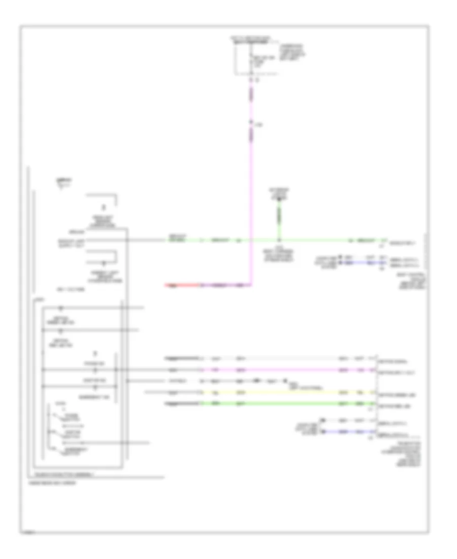
Pass-Key Wiring Diagram for Chevrolet Malibu LT 2014
List of elements for Pass-Key Wiring Diagram for Chevrolet Malibu LT 2014:
- (at hood latch) hood ajar switch
- (behind rear seats in luggage compt) (hybrid) hybrid/ev battery pack
- (left side of engine compt) (w/ start stop system) engine control module
- Batt pos volt
- Body control module (behind left side of dash)
- Computer data lines system
- Driver information center display
- Except hybrid
- Fuse 15a
- G101 (left front of engine compt)
- G203 (left kick panel)
- Gnd
- Hood ajar sw sig
- Hood open sw sig
- Hood open sw sig x1
- Hot at all times
- Hybrid
- Immobilizer control module (w/ keyless start: rear of floor console) (w/o keyless start: below steering wheel)
- Instrument cluster
- Instrument panel fuse block (left side of dash)
- J101
- J203
- Lo spd gmlan serial data
- Logic
- Low ref
- Network bus 11
- Security ind
- Starter/ generator control module
- Veh immobilizer rtn
- Veh sply volt
- W/ keyless engine start switch
- W/ start/stop system
- W/o start/stop system
- X115
- X150
- X300
BODY CONTROL MODULES
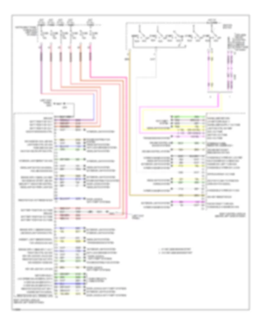
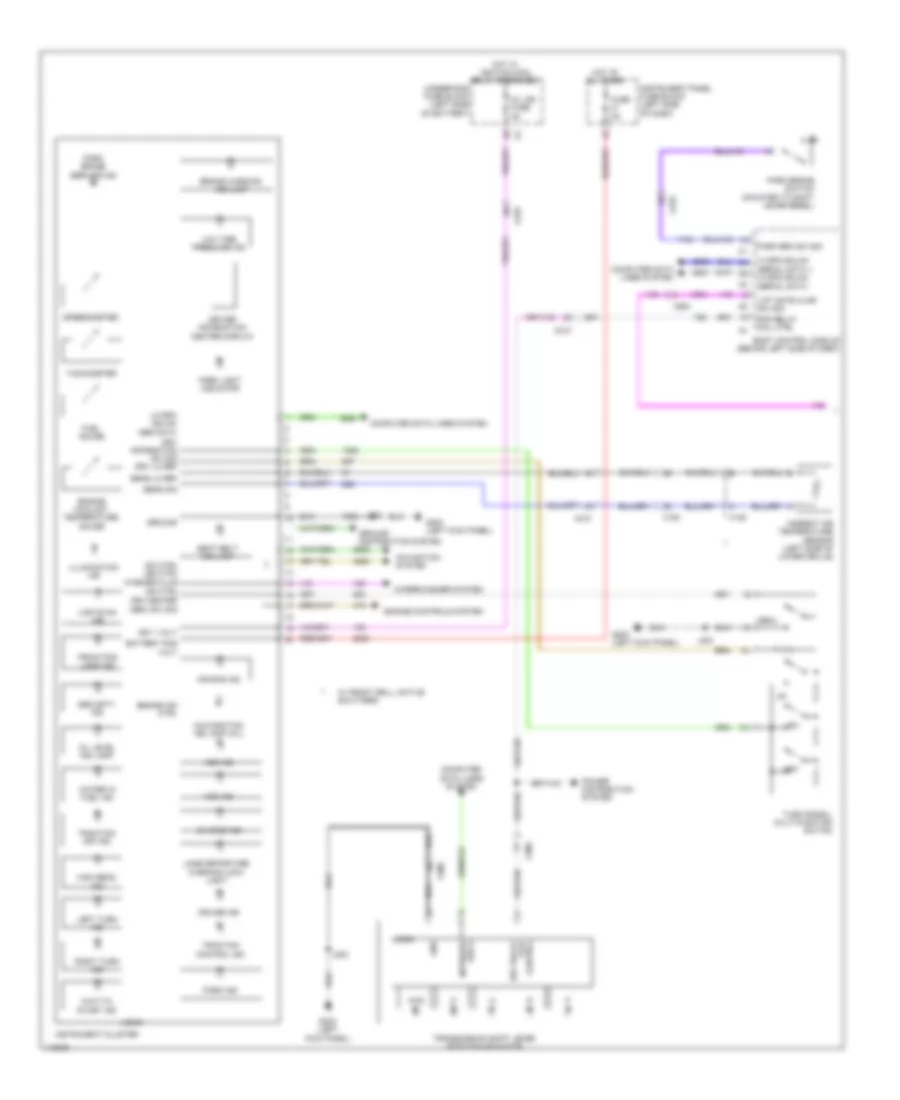
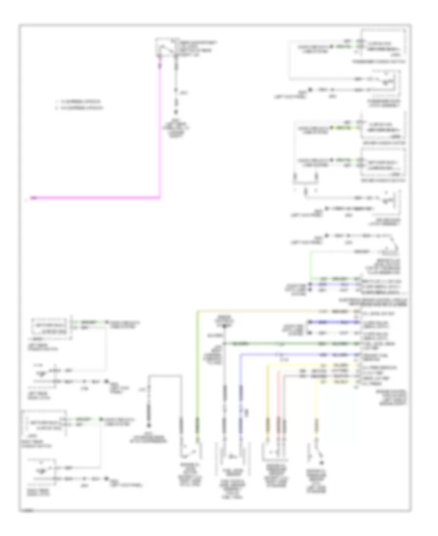
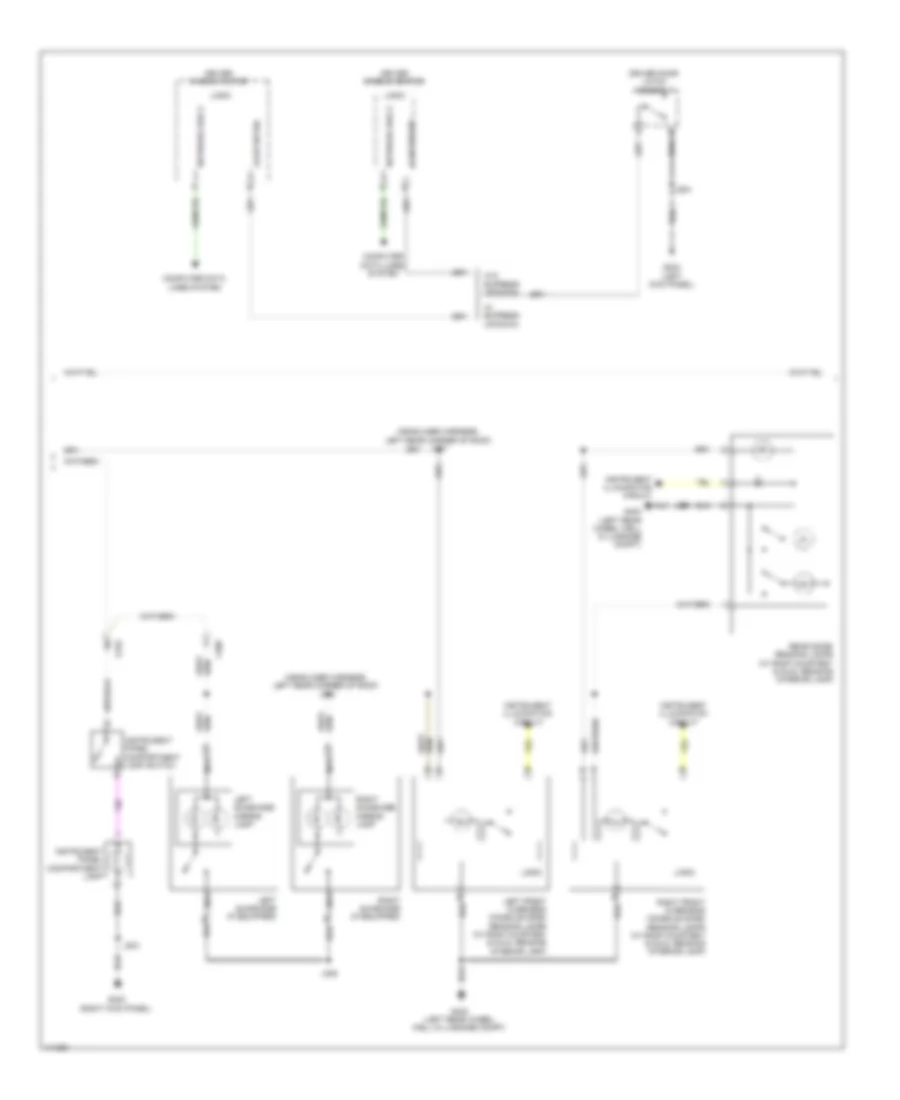
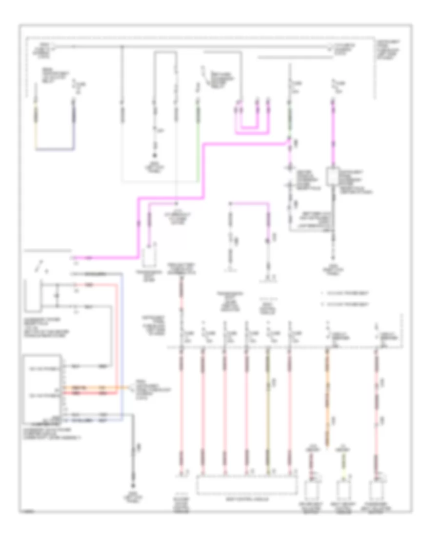
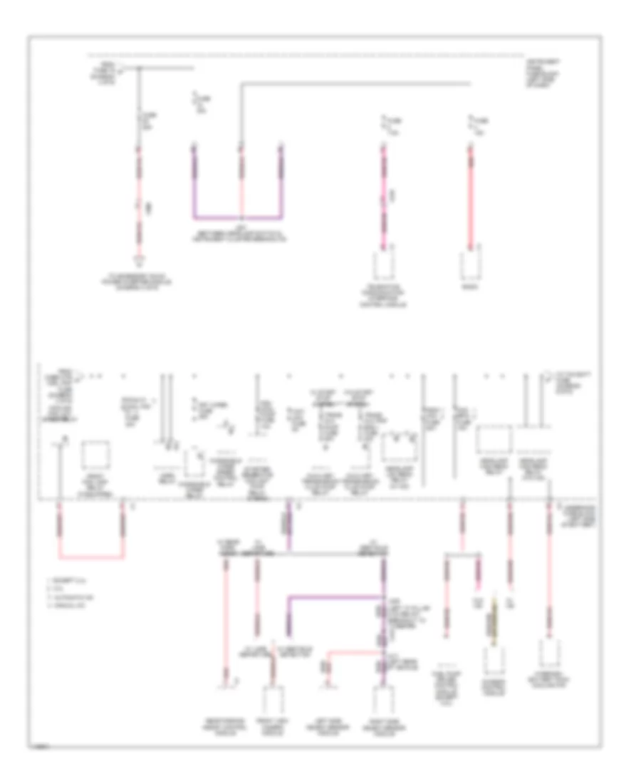
Body Control Modules Wiring Diagram (1 of 2) for Chevrolet Malibu LT 2014
List of elements for Body Control Modules Wiring Diagram (1 of 2) for Chevrolet Malibu LT 2014:
- (left kick panel)
- (left kick panel) g203
- Acc
- Acc volt
- Acc voltage
- Ambient light sensor signal
- Anti-lock brakes system
- Anti-theft system
- Batt positive volt
- Battery positive voltage
- Body control module (behind left side of dash)
- Computer data lines system
- Cruise control & sound systems
- Cruise control system
- Cruise set/coast/ resume/acc sw sig
- Door locks & anti-theft systems
- Door locks system
- Drv dr lock sw lck sig
- Drv dr lock sw unlck sig
- Exterior lights system
- Fuse 15a
- Fuse 30a
- G203
- Ground
- Haz led dimming sig
- Haz sw right turn sig
- Hazard sw left turn sig
- Hazard switch signal
- Hdlp dimmer sw hi beam sig
- Hdlp sw flash to pass sig
- Hdlp sw hdlps off sig ctrl
- Headlamp sw park lamp sig
- Headlamp switch on signal
- Headlights system
- Hi spd gmlan ser data (+)
- Hi spd gmlan ser data (-)
- Horn switch signal
- Horns system
- Hot at all times
- Ign key resistor sig
- Ign mode sw acc led sig
- Ign mode sw mode sig
- Ign mode sw start led sig
- Ignition switch
- Ignition voltage
- Immobilizer return
- Indicator dimming ctrl
- Instrument panel fuse block (left side of dash)
- Interior lamp defeat sw sig
- Interior lights system
- J203
- Keyless entry control module (behind right side of dash)
- Led backlight dimming ctrl
- Lighting ctrl sw ref
- Lightning ctrl sw sig
- Lin network bus 11
- Low speed gmlan serial data
- Network bus 4
- Off
- Off run
- Off/run/crank voltage
- Park brk sw sig
- Power distribution system
- Remote func act receive sig
- Remote func act transmit sig
- Remote function act rtn
- Remote function act sply
- Run
- Run/crank 1 volt
- Security indicator control
- Start
- Start off
- Steering wheel resistor ladder sig 1
- Tap up/down sw sig
- Traction ctrl sw sig
- Transmissions system
- W/ keyless engine start
- W/o keyless engine start
- Windshield washer sw sig
- Windshield wiper sw hi sig
- Windshield wiper sw lo sig
- Windshield wiper sw low ref
- Wiper/washer system
- X210
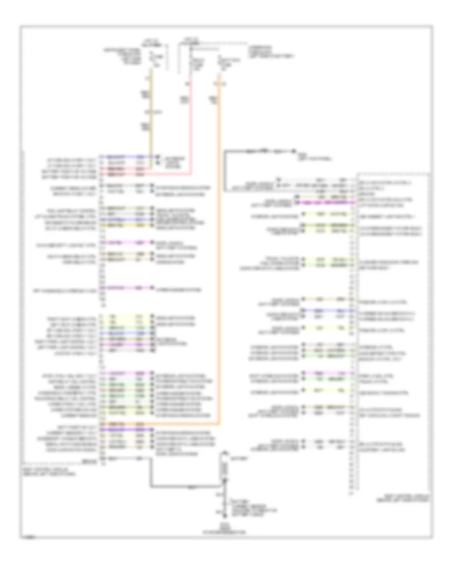
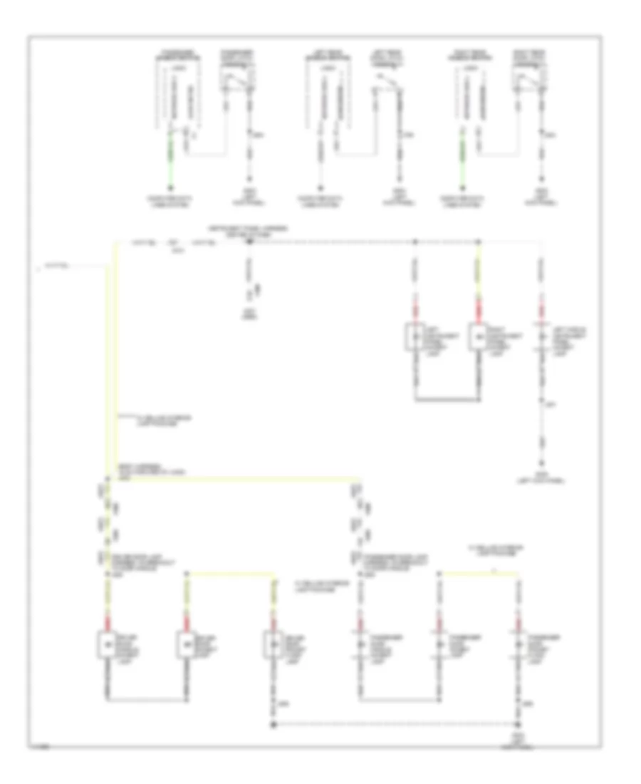
Body Control Modules Wiring Diagram (2 of 2) for Chevrolet Malibu LT 2014
List of elements for Body Control Modules Wiring Diagram (2 of 2) for Chevrolet Malibu LT 2014:
- (or 295)
- Accessory wakeup ser data
- Anti-theft & door locks systems
- Backup lp ctrl volt
- Batt positive volt
- Batt rvc fuse 5a
- Battery
- Battery positive voltage
- Bcm 6 fuse 15a
- Body control module (behind left side of dash)
- Child security lock rly ctrl
- Closure handle sw open sig
- Computer data lines system
- Courtesy lamp sw sig
- Cruise/etc/tcc brake sig
- Current sens low ref
- Current sens sig
- Current sens sply volt
- Door locks & anti-theft systems
- Door locks & anti-theft systems interior lights system
- Dr lk actuator lk ctrl 2
- Dr lk actuator unlk ctrl
- Dr lk ctrl 2
- Exterior lights system
- Fog lamp relay control
- Frt windshield wiper sw hi sig
- Fuse 15a
- G103 (near starter/generator)
- G305 (left kick panel)
- Ground
- Hd lp lo beam relay ctrl
- Hdlp hi beam relay ctrl
- Headlights system
- Headlights system trunk, tailgate, fuel doors system cruise control system
- Hi speed gmlan ser data (+)
- Hi speed gmlan ser data (-)
- Hood ajar switch signal
- Horn relay ctrl
- Horns system
- Hot at all times
- Inadvertent pwr ctrl
- Instrument panel fuse block (left side of dash)
- Interior lights system
- Interior lp ctrl
- J305
- Key cap/clmn lk shift pos sig
- Led ambient lighting ctrl 1
- Led backlt dimming ctrl
- Left hdlp lo beam ctrl
- Left park lamp control volt
- Lf turn sig lp sply volt
- Lift gate ajar sw sig
- Lift glass/trunk mtr rel ctrl
- Lin interconnect ntwrk bus 2
- Lin interconnect ntwrk bus 3
- Lr lk mtr status sig
- Lr stop lp sply volt
- Lr turn sig lp sply volt
- Network bus 1
- Park lk sol ctrl
- Pass dr lk sw lk ctrl
- Pass dr lk sw ulk ctrl
- Power distribution system
- Rap relay coil control
- Rear license lp ctrl
- Rf turn sig lp sply volt
- Right hdlp lo beam ctrl
- Right park lamp control volt
- Rr lk mtr status sig
- Rr stop lp sply volt
- Rr turn sig lp sply volt
- Run/crank relay coil control
- Serial data comm enable
- Shift interlock system
- Starting/charging system
- Stop lp rly coil sply volt
- Trunk lp ctrl
- Trunk, tailgate, fuel doors system
- Underhood fuse block (left side of battery)
- Windshield washer rly ctrl
- Wiper mtr park sw sig
- Wiper mtr rly coil ctrl
- Wiper/washer system
- X210
COMPUTER DATA LINES
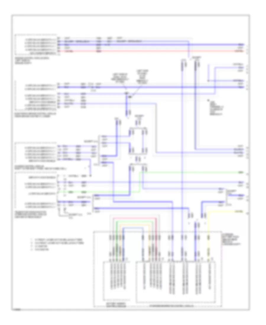
Computer Data Lines Wiring Diagram (1 of 4) for Chevrolet Malibu LT 2014
List of elements for Computer Data Lines Wiring Diagram (1 of 4) for Chevrolet Malibu LT 2014:
- (left side of dash, 49 cm from breakout of x500)
- (left side of dash, 51 cm from breakout of x500)
- 2.4l
- Acc wakeup ser data
- Battery energy control module
- Can bus hi 2 ser data
- Can bus hi ser data
- Can bus lo 2 ser data
- Can bus lo ser data
- Chassis control module (right outer body panel above wheelwell)
- Electronic brake control module (near brake master cylinder)
- Engine control module (ecm) (left side of engine compt)
- Except 2.4l
- Hi spd gmlan ser data (+) 1
- Hi spd gmlan ser data (+) 2
- Hi spd gmlan ser data (+) 3
- Hi spd gmlan ser data (-) 1
- Hi spd gmlan ser data (-) 2
- Hi spd gmlan ser data (-) 3
- Hydrid/ev battery pack (behind rear seats in luggage compt)
- J231
- J232
- J322 (body harness, 41 cm rear of x700 breakout)
- Lo spd gmlan ser data
- Ser data comm enable
- Starter/generator control module
- Telematics communication interface control module (center of rear shelf)
- W/ front lower active grille shutters
- W/ onstar
- W/o front lower active grille shutters
- W/o onstar
- X115
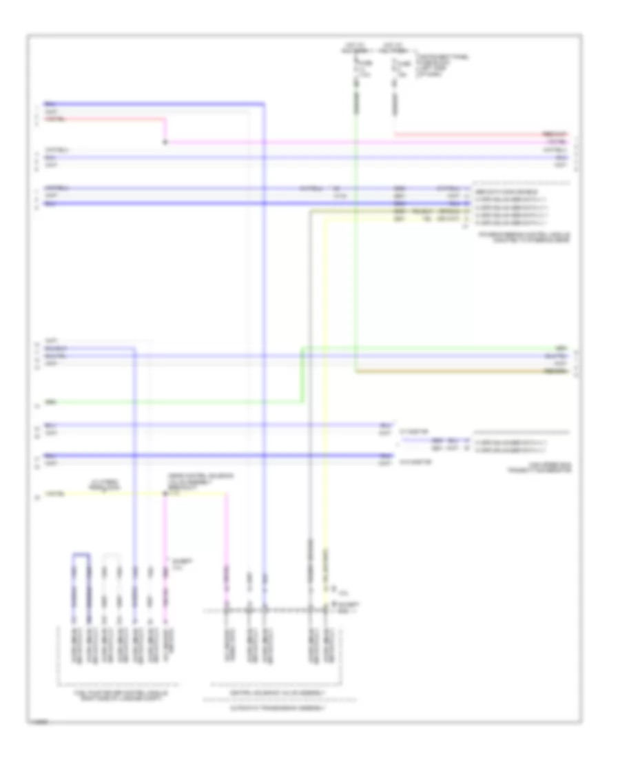
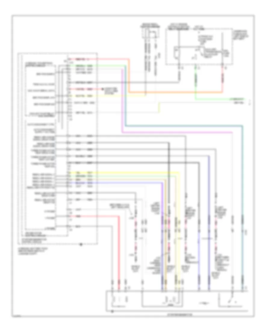
Computer Data Lines Wiring Diagram (2 of 4) for Chevrolet Malibu LT 2014
List of elements for Computer Data Lines Wiring Diagram (2 of 4) for Chevrolet Malibu LT 2014:
- (near control solenoid valve assembly breakout) j112
- 2.0l
- Acc wakeup
- Automatic transmission assembly
- Control solenoid valve assembly
- Except 2.0l
- Except 2.4l
- Fuel pump driver control module (right side of luggage compt)
- Fuse 15a
- Fuse 7.5a
- Hi spd gmlan
- Hi spd gmlan ser data (+) 1
- Hi spd gmlan ser data (-) 1
- High speed bus transmitting resistor
- Hot at all times
- Instrument panel fuse block (left side of dash)
- Power steering control module (mounted to steering gear)
- Ser data
- Ser data (+) 1 hi spd gmlan
- Ser data (+) 3
- Ser data (-) 1 hi spd gmlan
- Ser data (-) 3
- Ser data comm enable
- Serial data acc wakeup
- W/ hybrid propulsion
- W/ onstar
- W/o onstar
- X115
Computer Data Lines Wiring Diagram (3 of 4) for Chevrolet Malibu LT 2014
List of elements for Computer Data Lines Wiring Diagram (3 of 4) for Chevrolet Malibu LT 2014:
- (right "a" pillar, between x221 & x600 breakouts) j236
- (w/o keyless start: below steering wheel)
- Acc wakeup ser data
- Batt positive volt
- Battery sensor module (w/ start/stop engine) (left front engine compt)
- Body control module (behind left side of dash)
- Data link connector (dlc) (below steering column)
- Driver window motor (w/ express up/down)
- Driver window switch
- G203 (left kick panel)
- G305 (left kick panel)
- Hi spd gmlan ser data (+) 1
- Hi spd gmlan ser data (+) 2
- Hi spd gmlan ser data (-) 1
- Hi spd gmlan ser data (-) 2
- Immobilizer control module (w/ keyless start: rear of floor console)
- J201
- J203
- J237 (w/ start/ stop engine) (left side passenger compt near a pillar)
- J324 (body harness, on breakout to x700)
- J503 (w/ express up/down) (driver door harness, near door latch)
- Left rear window switch
- Lo spd gmlan ser data
- Logic
- Multi-axis acceleration sensor (below floor console)
- Network bus 1
- Network bus 11
- Network bus 2
- Network bus 3
- Network bus 4
- Right rear window switch
- Ser data comm enable
- Steering wheel angle sensor (forward of the steering wheel)
- Sunroof motor (if equipped) (front center of roof)
- Transmission shift lever position indicator
- W/ keyless engine start switch
- W/o front lower active grille shutters & onstar
- X115
- X210
- X300
- X500
- X700
- X800
Computer Data Lines Wiring Diagram (4 of 4) for Chevrolet Malibu LT 2014
List of elements for Computer Data Lines Wiring Diagram (4 of 4) for Chevrolet Malibu LT 2014:
- (body harness, in branch to floor console) (w/ memory) j332
- (not used)
- Front seat heating control module (below front center of the driver seat)
- Frontview camera module (w/ lane departure warning active safety)
- Hi spd gmlan (+) 5
- Hi spd gmlan (-) 5
- Hvac control module (center of dash)
- Hvac controls
- Inflatable restraint sensing & diagnostic module (forward of transmission shift lever on floor)
- Info display module (w/ navigation) (center of dash)
- Info display module (w/o navigation) (center of dash)
- Instrument cluster
- Jx200 (left side of dash)
- Jx300 (left rear door opening on floor)
- Keyless entry control module (w/ keyless engine start switch) (behind right side of dash)
- Left side object sensor module (if equipped) (left side of rear bumper)
- Lo spd gmlan ser data
- Lo spd gmlan serial data
- Logic
- Network bus 10
- Network bus 3
- Network bus 7
- Network bus 8
- Network bus 9
- Network bus 9 lo spd gmlan serial data
- Outside rear view mirror switch
- Passenger presence module (passenger seat between cover and cushion)
- Passenger window switch
- Radio
- Radio controls
- Rear parking assist control module (if equipped) (left side of luggage compt)
- Right side object sensor module (if equipped) (right side of rear bumper)
- Seat memory control module (w/ memory) (below front center of the driver seat)
- W/ memory
- W/o memory
- X210
- X310
- X320
- X415
- X500
- X600
COOLING FAN
Cooling Fan Wiring Diagram for Chevrolet Malibu LT 2014
List of elements for Cooling Fan Wiring Diagram for Chevrolet Malibu LT 2014:
- (not used)
- (rear of engine on cylinder head) g122
- Auxiliary heater coolant pump relay
- Batt + volt
- Battery fuse block (on battery)
- Cabin htr cool pmp fuse 10a
- Cfan k1 fuse 30a
- Cfan k2 fuse 30a
- Computer data lines system
- Cooling fan high speed relay
- Cooling fan low speed relay
- Cooling fan speed control relay
- Ecm batt fuse 5a
- Eng temp sens sig
- Engine control ignition relay
- Engine control module (ecm) (left side of engine compt)
- Engine cool ctrl
- Engine coolant temperature sensor (top rear of engine)
- Fan relay a fuse 10a
- Fuse 250a 200a
- G101 (left front of engine compt)
- G106 (upper left radiator support)
- G121 (on engine rear of a/c compressor)
- Gmlan serial data (+)
- Gmlan serial data (-)
- Gnd
- Heater coolant pump (near transmission)
- Hi spd fan rly ctrl
- Hot at all times
- J101
- J118 (near left headlamp assembly)
- J120
- J121
- J123
- Left cooling fan motor (left side of radiator)
- Lo spd fan rly ctrl
- Red
- Right cooling fan motor (right side of radiator)
- Sens lo ref
- Temp sens low ref 2
- Temp sens sig 2
- Underhood fuse block (left side of battery)
- W/ start/stop system
- W/o start/stop system
- X116
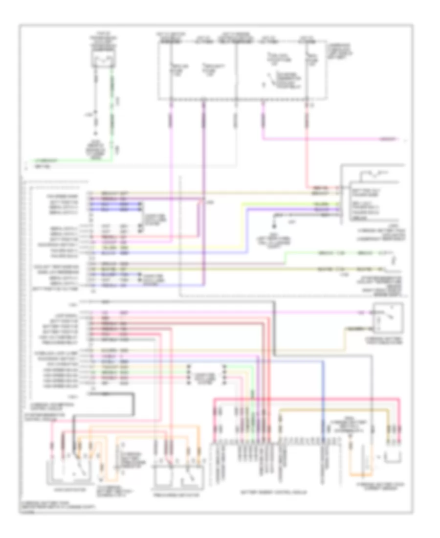
Hybrid Cooling Fan Wiring Diagram for Chevrolet Malibu LT 2014
List of elements for Hybrid Cooling Fan Wiring Diagram for Chevrolet Malibu LT 2014:
- 200a
- Batt pos volt
- Battery energy control module
- Battery fuse block (on battery)
- Bpim fuse 15a
- Can bus high 2 serial data
- Can bus low 2 serial data
- Computer data lines system
- Coolant pump rly coil ctrl
- Coolant temp sens sig
- Engine control ignition relay
- Fan spd sig (1)
- Fan spd sig (2)
- Fuse 250a
- G122 (rear of engine on cylinder head)
- G401 (left rear wheel well in luggage compt)
- Ground
- Hi spd high 2 serial data (+)
- Hi spd low 2 serial data (-)
- Hot at all times
- Hybrid/ev battery pack (behind rear seats in luggage compt)
- Hybrid/ev battery pack cooling fan (under right rear shelf)
- Hybrid/ev battery section 1
- Hybrid/ev battery section 2
- Hybrid/ev battery temperature sensor 1
- Hybrid/ev battery temperature sensor 2
- Hybrid/ev battery temperature sensor 3
- Hybrid/ev battery temperature sensor 4
- Hybrid/ev battery temperature sensor 5
- Hybrid/ev battery temperature sensor 6
- Hybrid/ev powertrain control module
- Inlet hybrid/ ev battery pack air temperature sensor
- J120
- J401
- Logic
- Mgu cool pmp fuse 10a
- Red
- Sens low ref
- Starter/ generator coolant pump (lower left rear of engine)
- Starter/ generator coolant pump relay
- Starter/ generator coolant temperature sensor (right front side of engine compt)
- Starter/generator control module
- Temp signal
- Underhood fuse block (left side of battery)
- W/ start/stop system
- W/o start/stop system
- Wakeup ser data
- X115
- X150
CRUISE CONTROL
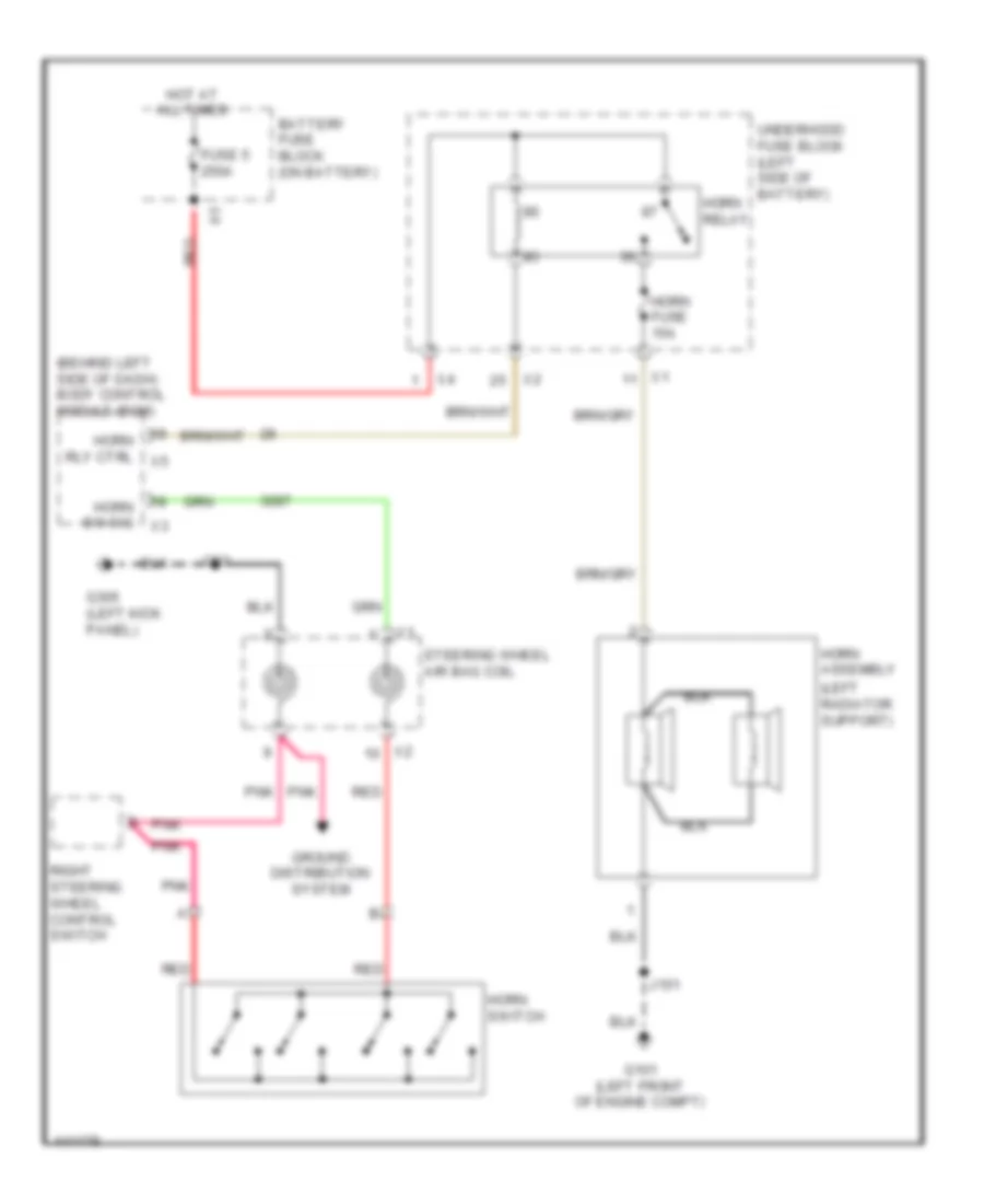
Cruise Control Wiring Diagram for Chevrolet Malibu LT 2014
List of elements for Cruise Control Wiring Diagram for Chevrolet Malibu LT 2014:
- (or 3630)
- 2.0l
- 2.0l & 2.4l
- 2.5l
- 2.5l & 2.4l
- 5 volt ref
- 5 volt ref (1)
- 5 volt reference
- 5 volt reference (2)
- Acc pedal pos lo ref (1)
- Acc pedal pos lo ref (2)
- Acc pedal pos sig (2)
- Acc pedal position sig (1)
- Accelerator pedal position sensor (app) (above accelerator pedal)
- Automatic transmission assembly
- Batt rcv fuse 5a
- Battery positive volt
- Body control module (bcm) (behind left side of dash)
- Brake pedal position sensor
- Brk position sens lo ref
- Brk position sens sig
- Cancel
- Computer data lines system
- Control solenoid valve assembly
- Cruise control sw sig
- Cruise indicator
- Cruise switch
- Cruise/etc/tcc brk sig
- Driver information center display
- Ecm batt fuse 5a
- Engine control module (ecm) (left side of engine compt)
- Except hybrid
- G121 (on engine rear of a/c compressor)
- Headlights & interior lights systems
- Hi sig
- Hi spd gmlan ser data (+) 1 hi speed gmlan serial data (-) 1
- Hi speed gmlan serial data (+) 1
- Hi speed gmlan serial data (-) 1
- Hot at all times
- Hybrid
- Hybrid/ev battery pack (behind rear seats in luggage compt)
- Hybrid/ev powertrain control module
- Instrument cluster
- J121
- J212 (on breakout to body control module connector x3)
- Left steering wheel control switch
- Lighting ctrl sw ref
- Lo sig
- Lo speed gmlan serial data
- Logic
- Of battery)
- Res
- Right steering wheel control switch
- Ser data (+)
- Ser data (-)
- Set-
- Signal ground
- Starter/generator control module
- Steering wheel air bag coil
- Throttle act ctrl close
- Throttle act ctrl open
- Throttle body (2.4l: left side of engine) (2.0l & 2.5l: right side of engine)
- Throttle post sens lo ref
- Throttle post sens sig (1)
- Transmission control module (tcm)
- Transmission input shaft speed sensor
- Transmission output shaft speed sensor
- Underhood fuse block (left side
- X115
- X210
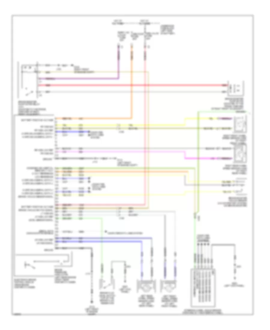
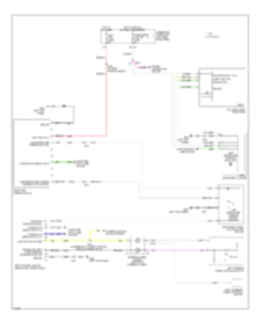
DEFOGGERS
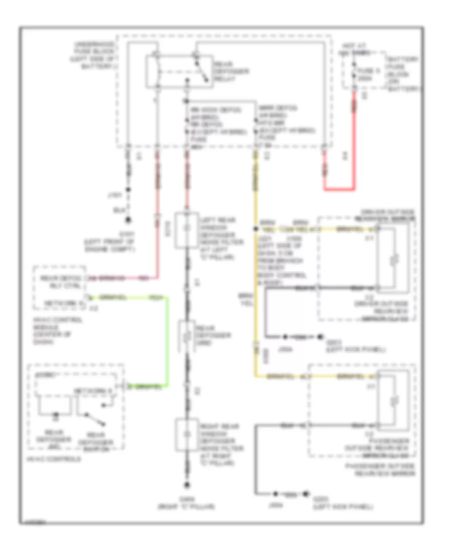
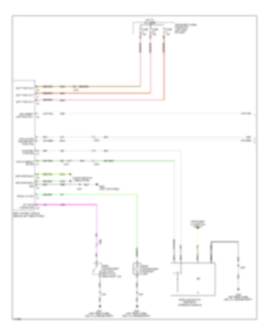
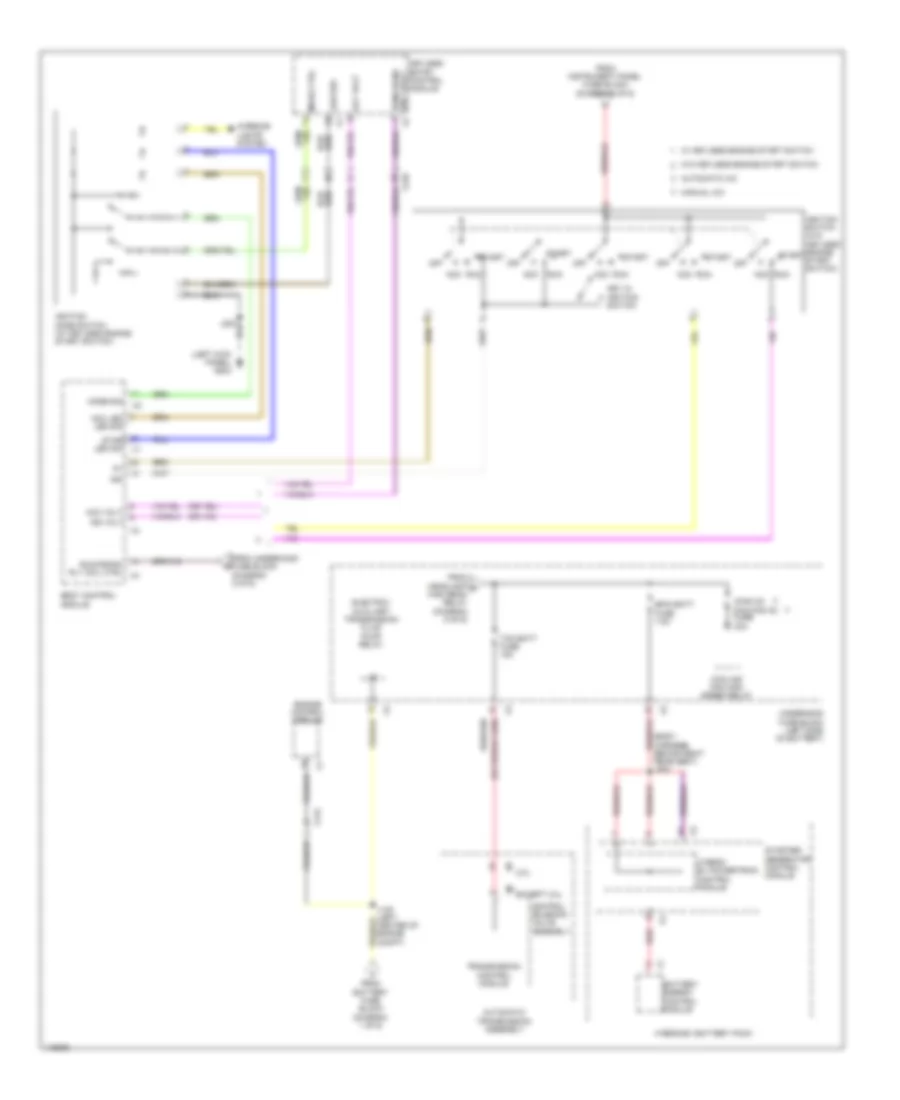
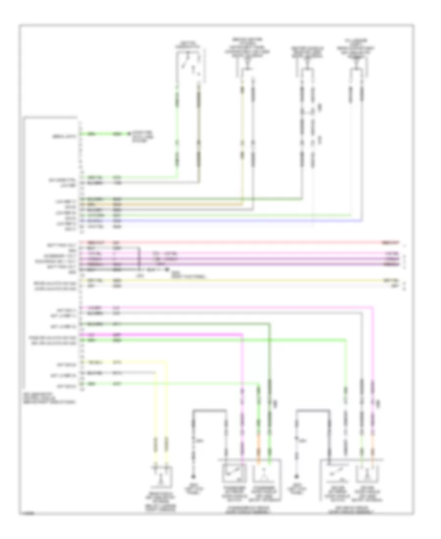
Defoggers Wiring Diagram for Chevrolet Malibu LT 2014
List of elements for Defoggers Wiring Diagram for Chevrolet Malibu LT 2014:
- Battery fuse block (on battery)
- Driver outside rearview mirror
- Driver outside rearview mirror glass
- Fuse 5 200a
- G101 (left front of engine compt)
- G203 (left kick panel)
- G404 (right "c" pillar)
- Hot at all times
- Hvac control module (center of dash)
- Hvac controls
- J101
- J221 (left side of dash, 5 cm from branch to body body control & roof)
- J504
- J604
- Left rear window defogger noise filter (at left "c" pillar)
- Logic
- Mirr defog (hybrid) htd mir (except hybrid) fuse 7.5a
- Nca
- Network 9
- Passenger outside rearview mirror
- Passenger outside rearview mirror glass
- Rear defog rly ctrl
- Rear defogger grid
- Rear defogger ind
- Rear defogger relay
- Rear defogger switch
- Red
- Right rear window defogger noise filter (at right "c" pillar)
- Rr wdw defog (hybrid) rr defog (except hybrid) fuse 40a
- Underhood fuse block (left side of battery)
- X210
- X500
- X600
ELECTRONIC POWER STEERING
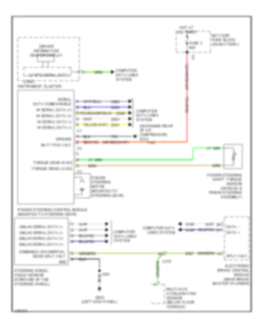
Electronic Power Steering Wiring Diagram for Chevrolet Malibu LT 2014
List of elements for Electronic Power Steering Wiring Diagram for Chevrolet Malibu LT 2014:
- (on engine rear of a/c compressor) g121
- Batt pos volt
- Battery fuse block (on battery)
- Combined veh inertial sens sply volt
- Computer data lines system
- Data +
- Data -
- Driver information center display
- Electronic brake control module (near brake master cylinder)
- Fuse 3 80a
- G203 (left kick panel)
- Gmlan serial data (+)
- Gmlan serial data (-)
- Gnd
- Ground
- Hi serial data (+)
- Hi serial data (-)
- Hot at all times
- Instrument cluster
- J203
- Lo spd serial data
- Logic
- Multi-axis acceleration sensor (below floor console)
- Power steering control module (mounted to steering gear)
- Power steering motor (mounted to steering gear)
- Power steering shaft torque sensor (on rack & pinion steering assembly)
- Serial data comm enable
- Sply volt
- Steering wheel angle sensor (forward of the steering wheel)
- Torque sens hi sig
- Torque sens lo sig
- X210
ENGINE PERFORMANCE
2.0L VIN X
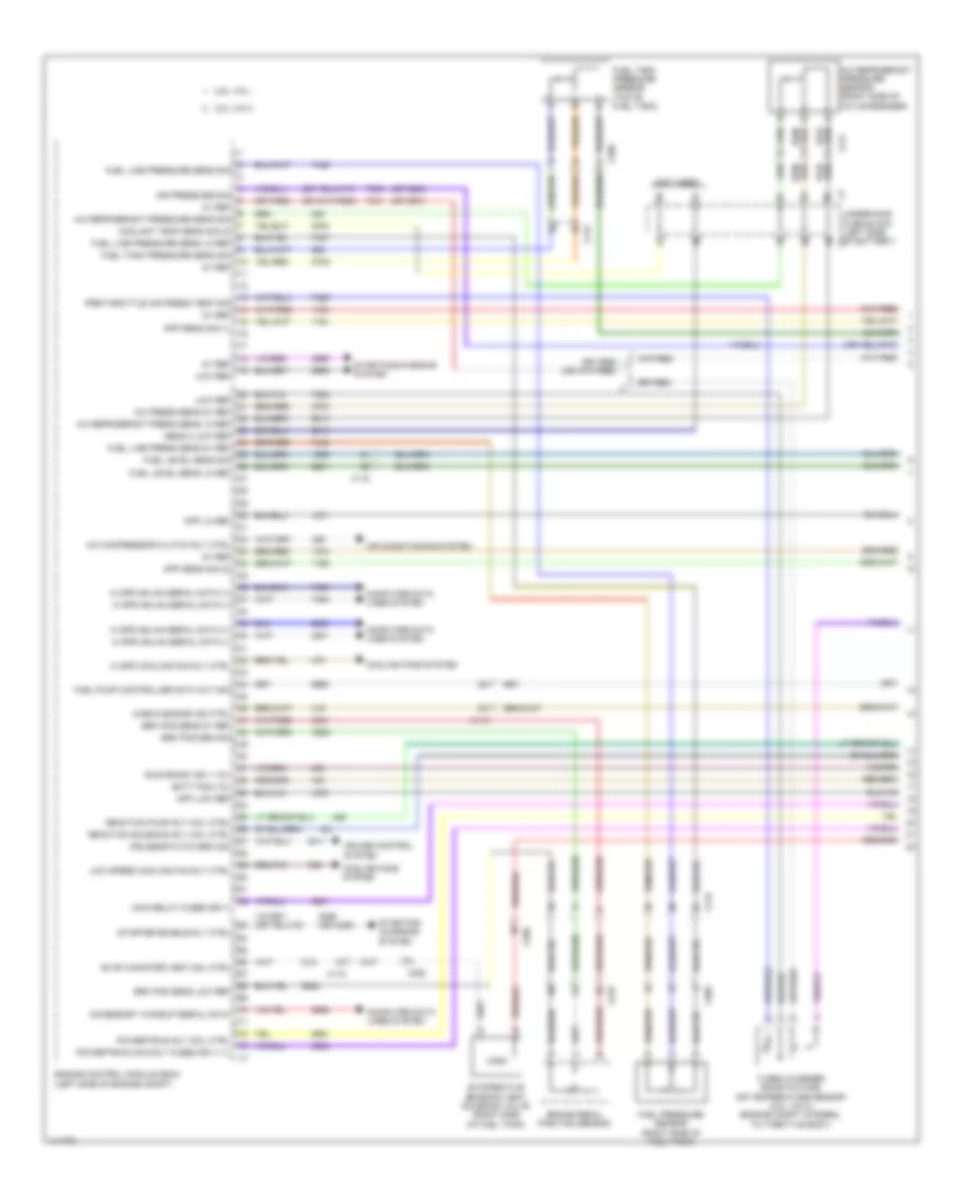
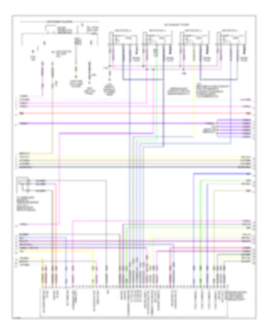
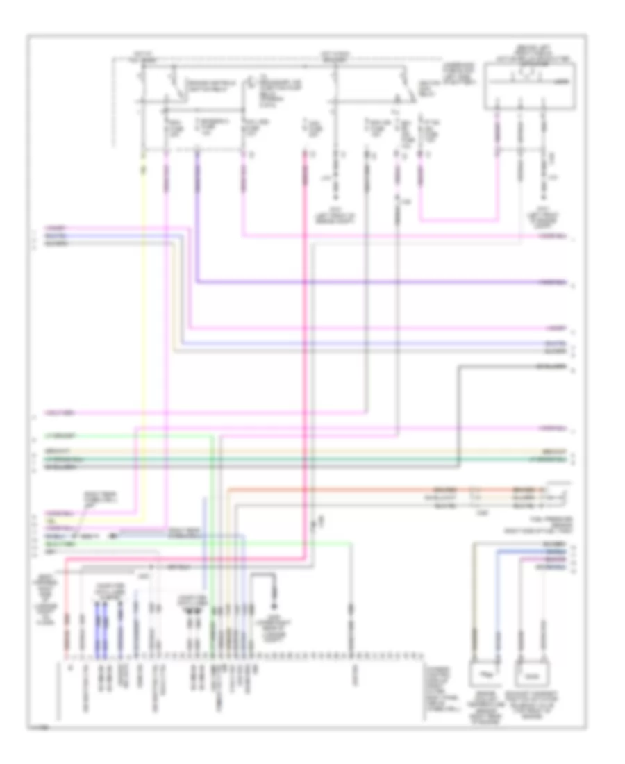
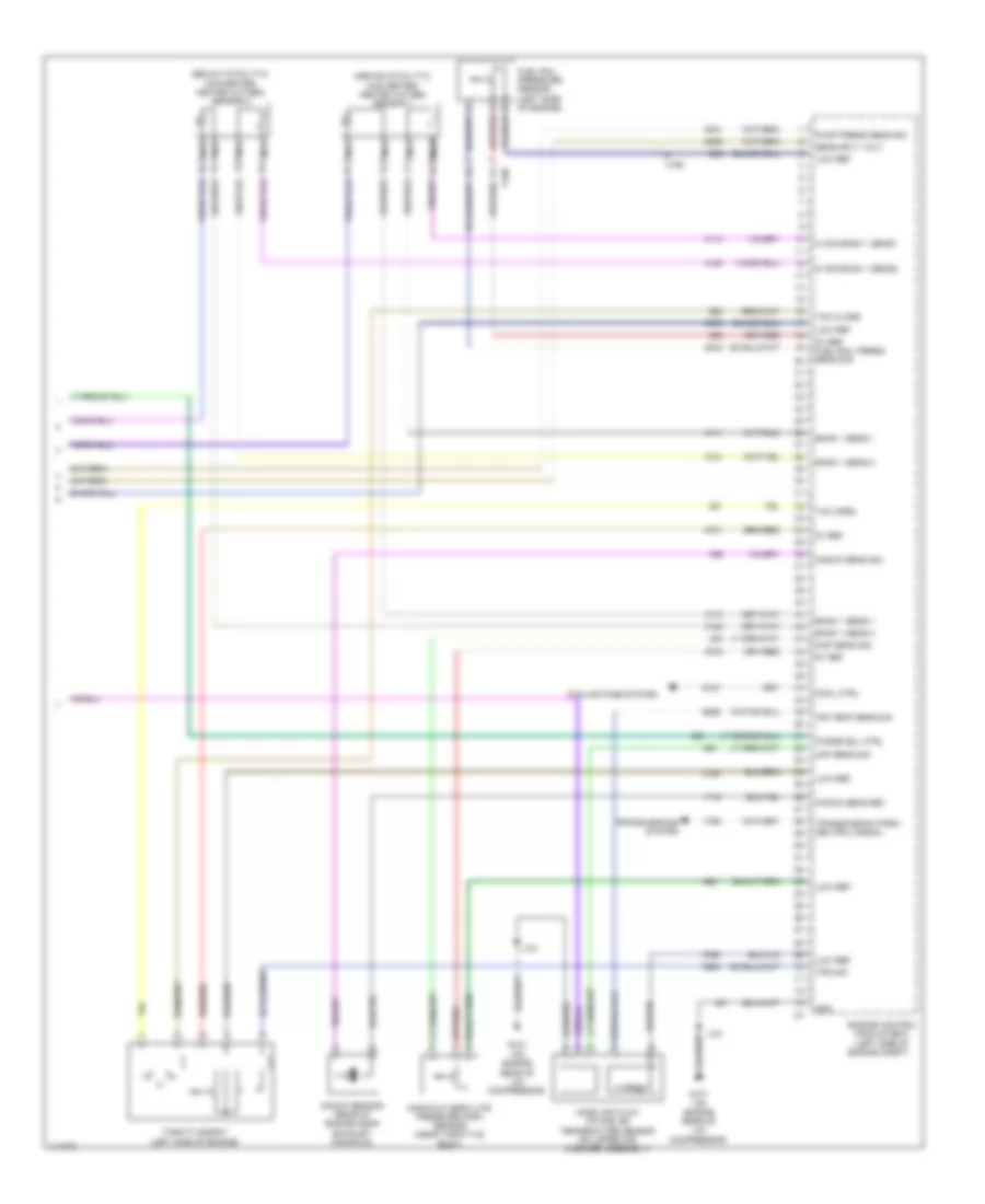
2.0L VIN X, Engine Performance Wiring Diagram (1 of 6) for Chevrolet Malibu LT 2014
List of elements for 2.0L VIN X, Engine Performance Wiring Diagram (1 of 6) for Chevrolet Malibu LT 2014:
- (not used)
- (or 3200)
- (or 3201)
- (or 4325)
- 2.0l vin x
- 2.5l vin l
- 5v ref
- A/c compressor clutch rly ctrl
- A/c press sens 5v ref
- A/c refrigerant press sens lo ref
- A/c refrigerant pressure sens sig
- A/c refrigerant pressure sensor (right side of a/c condenser)
- Accessory wakeup serial data
- Air conditioning system
- Air pressure sig
- App lo ref
- App low ref
- App sens sig (1)
- App sens sig (2)
- Batt pos vol
- Brake pedal position sensor
- Brk pos sen sig
- Brk pos sens 5v ref
- Brk pos sens low ref
- Check engine ind ctrl
- Computer data lines system
- Coolant temp sens sig (2)
- Cooling fans system
- Cruise control system
- Cruise\etc\tcc brk sig
- Engine control module (ecm) (left side of engine compt)
- Evap canister vent sol ctrl
- Evaporative emission vent solenoid valve (right side of fuel tank)
- Fuel level sens lo ref
- Fuel level sens sig
- Fuel line press sens 5v ref
- Fuel line pressure sens lo ref
- Fuel line pressure sens sig
- Fuel pressure sensor (right side of fuel tank)
- Fuel pump controller data out sig
- Fuel tank pressure sens sig
- Fuel tank pressure sensor (top of fuel tank)
- Hi spd cooling fan rly ctrl
- Hi spd gmlan serial data (+)
- Hi spd gmlan serial data (-)
- Low ref
- Low speed cooling fan rly ctrl
- Main relay fused sply
- Powertrain main rly fused sply (1)
- Powertrain rly coil ctrl
- Pre-throttle air press temp sig
- Reaction pump rly coil ctrl
- Reaction solenoid rly coil ctrl
- Run/crank ign 1 vol
- Sens 2 low ref
- Starter enable rly ctrl
- Starting/ charging system
- Starting/charging system
- Turbo charger boost/intake air temperature sensor (2.0l vin x) (engine compt integral to throttle body)
- Underhood fuse block (left side of battery) x3
- X115
- X117
- X210
- X350
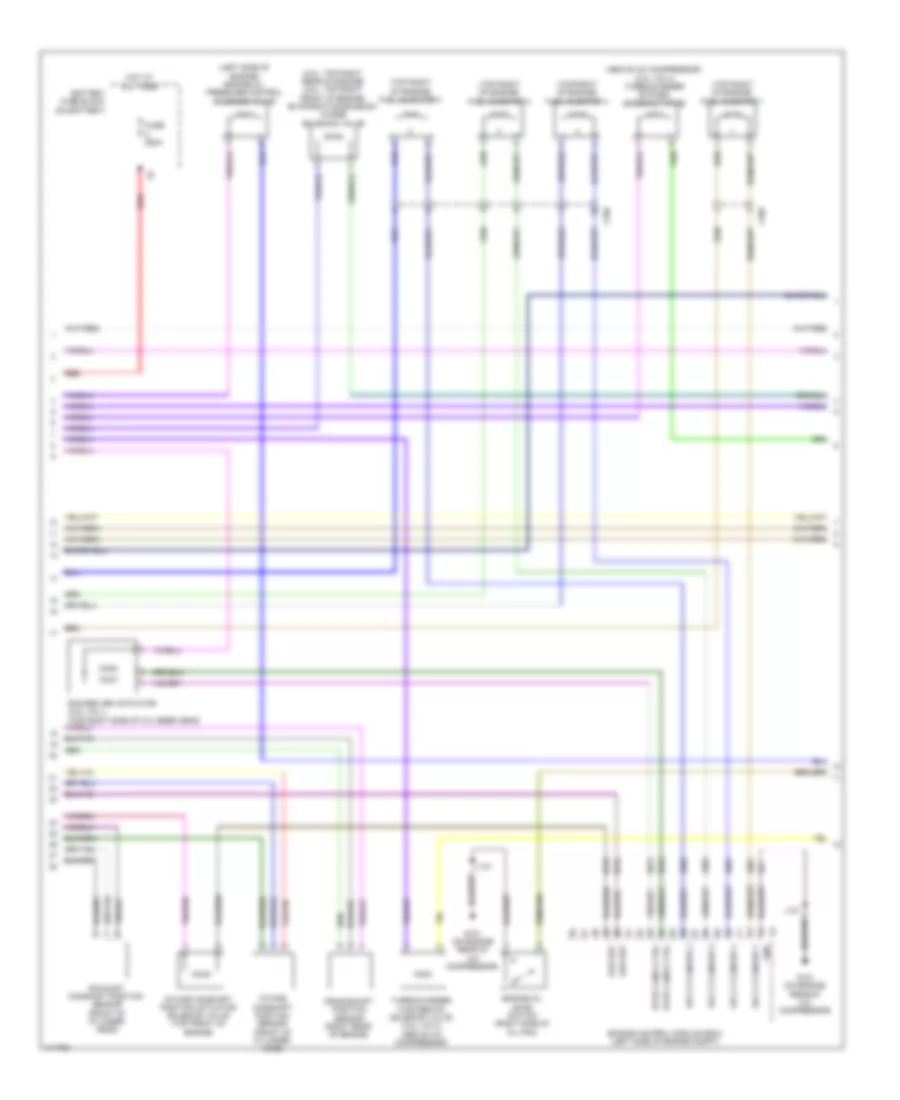
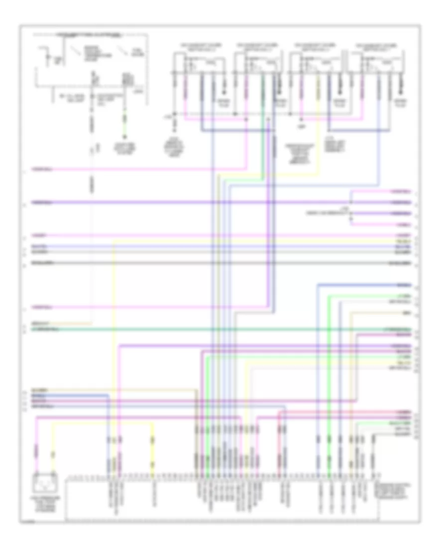
2.0L VIN X, Engine Performance Wiring Diagram (2 of 6) for Chevrolet Malibu LT 2014
List of elements for 2.0L VIN X, Engine Performance Wiring Diagram (2 of 6) for Chevrolet Malibu LT 2014:
- (above accelerator pedal) accelerator pedal position sensor
- 2.0l vin x
- 2.5l vin l
- Batt pos volt
- Computer data lines system
- From engine controls ignition relay (diagram 3 of 6)
- Fuel level sensor
- Fuel pump
- Fuel pump & level sensor assembly (top of fuel tank)
- Fuel pump driver control module (right side of luggage compt)
- G122 (rear of engine on cylinder head)
- G405 (upper right rear of luggage compt)
- Gmlan ser data (+)
- Gmlan ser data (-)
- Gnd
- Hot at all times
- Ignition 1 volt
- J120
- J406 (w/ vri)
- J434 (body harness, in branch to x420)
- J435
- J457 (right rear wheelwell)
- Low ref
- Nca
- Out sig
- Sair sol fuse 15a
- Sec air pump fuse 50a
- Secondary air injection pump (2.5l: right side of engine)
- Secondary air injection pump relay (california emission system)
- Secondary air injection solenoid valve relay (california emission system)
- Shield extension
- Sply volt
- Underhood fuse block (left side of battery)
- Wakeup serial data
- X114
- X115
- X210
- X350
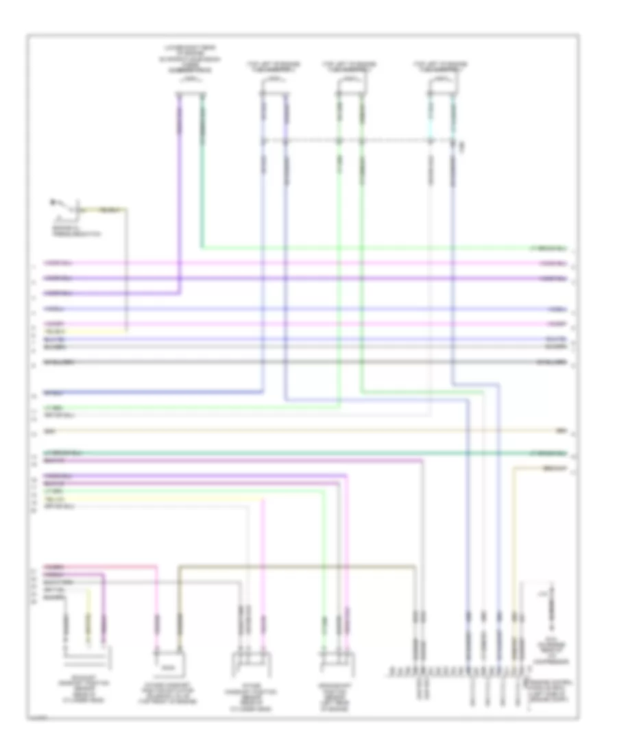
2.0L VIN X, Engine Performance Wiring Diagram (3 of 6) for Chevrolet Malibu LT 2014
List of elements for 2.0L VIN X, Engine Performance Wiring Diagram (3 of 6) for Chevrolet Malibu LT 2014:
- 2.0l vin x
- 2.5l vin l
- Coil odd fuse 15a
- Cps fuse 10a
- Ecm batt fuse 5a
- Ecm fuse 20a
- Ecm ign fuse 5a
- Emission 1 fuse 10a
- Emission 2 fuse 10a
- Engine controls ignition relay
- Engine coolant temperature sensor
- Engine oil pressure sensor (right side of engine)
- Exhaust camshaft position actuator solenoid valve (top front of engine)
- Fscm fuse 20a
- G101 (left front of engine compt)
- G122 (rear of engine on cylinder head)
- High pressure fuel pump (top rear of engine)
- Hot at all times
- Hot in run or start
- Ignition main relay
- J120
- Mil ign fuse 5a
- Red
- Secondary air injection solenoid valve (california emission system) (2.5l: top rear of engine)
- Tc fsc ign fuse 7.5a
- To secondary air injection pump relay (diagram 2 of 6)
- Underhood fuse block (left side of battery)
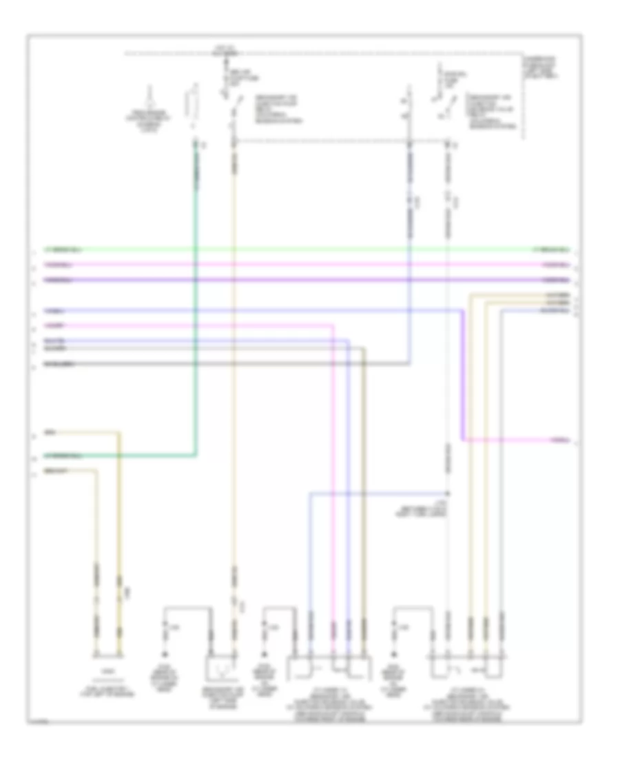
2.0L VIN X, Engine Performance Wiring Diagram (4 of 6) for Chevrolet Malibu LT 2014
List of elements for 2.0L VIN X, Engine Performance Wiring Diagram (4 of 6) for Chevrolet Malibu LT 2014:
- (near exhaust camshaft position sensor breakout)
- (on camshaft cover)
- 5v ref
- Actuator hi ctrl
- Actuator low ctrl
- Camshaft pos intake
- Computer data lines system
- Crankshaft 60x sens volt
- Crankshaft sens sig
- Ctrl cylinder 1
- Ctrl cylinder 2
- Ctrl cylinder 3
- Ctrl cylinder 4
- Cylinder head engine oil pressure sensor (2.5l vin l) (engine compt rear of engine)
- Data
- Driver information center (dic)
- Ect sens sig
- Engine control module (ecm) (left side of engine compt)
- Exhaust sens (1)
- Exhaust sol (1)
- Fuel ind
- G122 (rear of engine on cylinder head)
- G203 (left kick panel)
- Gnd
- Ic ctrl (1)
- Ic ctrl (2)
- Ic ctrl (3)
- Ic ctrl (4)
- Ign
- Ignition coil 1
- Ignition coil 2
- Ignition coil 3
- Ignition coil 4
- Instrument cluster
- Intake sol (1)
- J103 (between intake camshaft position sensor & evaporative emission purge solenoid valve breakouts)
- J106
- J108 (near x160 breakout)
- J122
- J203
- Logic
- Low ref
- Low ref bank 1
- Malfunction ind lamp (mil)
- Nca
- Oil level ind lamp
- Oil press sens sig
- Red
- Sens lo ref
- Serial gmlan
- Sig
- Spark plug
- Sply volt
- X210
2.0L VIN X, Engine Performance Wiring Diagram (5 of 6) for Chevrolet Malibu LT 2014
List of elements for 2.0L VIN X, Engine Performance Wiring Diagram (5 of 6) for Chevrolet Malibu LT 2014:
- (2.0l: top right rear of engine) (2.5l: top right front of engine) evaporative emission purge solenoid valve
- (above a/c compressor) (2.0l vin x) turbocharger bypass solenoid valve
- (left side of engine) engine oil pressure control solenoid valve
- (top right of engine)
- (top right of engine) fuel injector 2
- (top right of engine) fuel injector 3
- (top right of engine) fuel injector 4
- Battery fuse block (on battery)
- Crankshaft position sensor (right rear of engine)
- Engine control module (ecm) (left side of engine compt)
- Engine oil level switch (right side of oil pan)
- Exhaust camshaft position sensor (front of cylinder head)
- Fuel injector 1
- Fuse 250a
- G121 (on engine rear of a/c compressor)
- Gnd
- Hot at all times
- Intake camshaft position actuator solenoid valve (top front of engine)
- Intake camshaft position sensor (front of cylinder head)
- J121
- Low ref
- Red
- Sply cylinder 1
- Sply cylinder 2
- Sply cylinder 3
- Sply cylinder 4
- Step cam a ctrl
- Step cam b ctrl
- Turbocharger wastegate solenoid valve (2.0l vin x) (above a/c compressor)
- X160
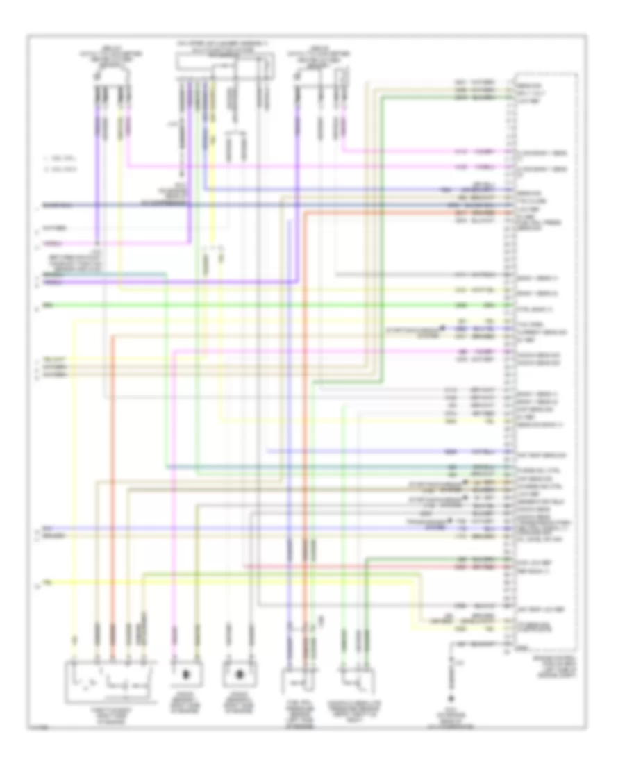
2.0L VIN X, Engine Performance Wiring Diagram (6 of 6) for Chevrolet Malibu LT 2014
List of elements for 2.0L VIN X, Engine Performance Wiring Diagram (6 of 6) for Chevrolet Malibu LT 2014:
- (above catalytic converter) heated oxygen sensor 1
- (below catalytic converter) heated oxygen sensor 2
- (on upper air cleaner assembly) multi-function intake air sensor
- (or 3630)
- 2.0l vin x
- 2.5l vin l
- 5v ref
- 5v ref fuel rail press sens sig
- Air temp low ref
- Air temp sens sig
- Bank 1 sens (1)
- Bank 1 sens (2)
- Charge ind ctrl
- Ctrl bank (1)
- Current sens sig
- Engine control module (ecm) (left side of engine compt)
- Fuel rail pressure sensor (left side of engine)
- G121 (on engine rear of a/c compressor)
- Generator field
- Gnd
- Hi sig bank 1 sens (1)
- Hi sig bank 1 sens (2)
- J107 (between exhaust camshaft position sensor and g122)
- J121
- Knock sens
- Knock sens sig
- Knock sens transmission park/ neutral signal (1) command sig
- Knock sensor 1 (right side of engine)
- Knock sensor 2 (right side of engine)
- Low ref
- Maf sens sig
- Manifold absolute pressure sensor (near throttle body)
- Map low ref
- Map sens sig
- Nca
- Oil level sw sig
- Purge sol ctrl
- Ref bank (1)
- Sens sig
- Sens sig bank (1)
- Sply volt
- Starting/charging system
- Tac close
- Tac open
- Throttle body (right side of engine)
- Tp sens sig waste gate
- Transmissions system
- X160
2.4L VIN R
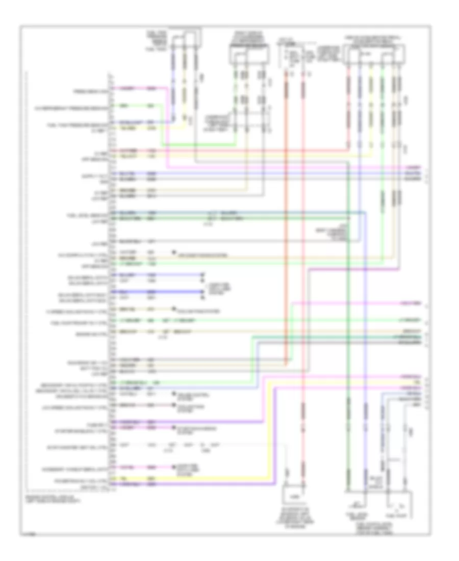
2.4L VIN R, Engine Controls Wiring Diagram (1 of 6) for Chevrolet Malibu LT 2014
List of elements for 2.4L VIN R, Engine Controls Wiring Diagram (1 of 6) for Chevrolet Malibu LT 2014:
- (above accelerator pedal) accelerator pedal position (app) sensor
- (right side of a/c condenser) a/c refrigerant pressure sensor
- 5v ref
- 5v ref 1
- A/c compr clth rly ctrl
- A/c refrigerant pressure sens sig
- Accessory wakeup serial data
- Air conditioning system
- App sens sig
- Batt pos vol
- Computer data lines system
- Cooling fans system
- Cps fuse 10a
- Cruise control system
- Cruise/etc/tcc brake sig
- Ecm batt fuse 5a
- Engine control module (left side of engine compt)
- Engine ind ctrl
- Evap canister vent sol ctrl
- Evaporative emission vent solenoid valve (lower right rear of engine)
- Fuel level sens sig
- Fuel level sensor
- Fuel pump
- Fuel pump & level sender assembly (top of fuel tank)
- Fuel pump primary rly ctrl
- Fuel tank pressure sens sig
- Fuel tank pressure sensor (top of fuel tank)
- Fuse sply
- Gmlan serial data bus +
- Gmlan serial data bus -
- Gmlan serial data+
- Gmlan serial data-
- Gnd
- Hi speed cooling fan rly ctrl
- Hot at all times
- Ignition 1 vol
- J434 (body harness, in branch to x420)
- Low ref
- Low speed cooling fan rly ctrl
- Nca
- Powertrain rly coil ctrl
- Press sens 2 sig
- Run/crank ign 1 vol
- Secondary air inj pump rly ctrl
- Secondary air inj sol val rly ctrl
- Starter enable rly ctrl
- Starting/charging system
- Underhood fuse block (left side of battery)
- X115
- X117
- X210
- X350
2.4L VIN R, Engine Controls Wiring Diagram (2 of 6) for Chevrolet Malibu LT 2014
List of elements for 2.4L VIN R, Engine Controls Wiring Diagram (2 of 6) for Chevrolet Malibu LT 2014:
- (behind left front fascia) active grille air shutter actuator
- (body harness, right side of luggage compt on floor)
- (right rear wheelwell)
- (right rear wheelwell) j457
- 5 volt ref
- Air shutter ctrl
- Bdy rc ign fuse 10a
- Ccm fuse 20a
- Chassis control module (right outer body panel above wheelwell)
- Coil odd fuse 15a
- Computer data lines system
- Drain wire
- Ecm fuse 20a
- Ecm ign fuse 15a
- Emission 2 fuse 10a
- Engine controls ignition relay
- Engine coolant temperature sensor (right rear of engine)
- Exhaust camshaft position actuator solenoid valve (top front of engine)
- Fuel pressure sensor (right side of fuel tank)
- Fuel pump
- G101 (left front of engine compt)
- G405 (upper right rear of luggage compt)
- Gnd
- Hot at all times
- Hot in run or start
- Hs gmlan+
- Hs gmlan-
- Ignition main relay
- J101
- J136
- J303
- J435
- Logic
- Low ref
- Nca
- Primary rly ctrl ign
- Pt rc ign fuse 7.5a
- Relay ctrl
- Sens sig
- Srl data
- To secondary air injection pump relay (diagram 5 of 6)
- Underhood fuse block (left side of battery)
- Wakeup
- X125
- X150
- X350
2.4L VIN R, Engine Controls Wiring Diagram (3 of 6) for Chevrolet Malibu LT 2014
List of elements for 2.4L VIN R, Engine Controls Wiring Diagram (3 of 6) for Chevrolet Malibu LT 2014:
- (near exhaust camshaft position sensor breakout)
- (near left headlamp assembly)
- (on camshaft cover) ignition coil 1
- (on camshaft cover) ignition coil 2
- (on camshaft cover) ignition coil 3
- (on camshaft cover) ignition coil 4
- 5-volt 2 ref
- Actu hi ctrl
- Actu low ctrl
- Cam pos intake
- Computer data lines system
- Crank sens sig
- Ctrl cylinder 1
- Ctrl cylinder 2
- Ctrl cylinder 3
- Ctrl cylinder 4
- Data
- Ect sens sig
- Eng ind ctrl
- Engine control module (ecm) (left side of engine compt)
- Engine coolant temperature gauge
- Exh sens
- Exhaust sol
- Fuel gauge
- Fuel ind
- G122 (rear of engine on cylinder head)
- Gmlan serial
- High pressure fuel pump (top rear of engine)
- Ign ctrl 1
- Ign ctrl 2
- Ign ctrl 3
- Ign ctrl 4
- Instrument panel cluster (ipc)
- Intake sens
- Intake sol
- J106
- J108 (near x160 breakout)
- J118
- J122
- Logic
- Low ref
- Low ref (1)
- Low ref bank 1
- Malfunction ind lamp (mil)
- Nca
- Oil level ind lamp
- Oil press sw sig
- Spark plug
- Sply volt
- X210
2.4L VIN R, Engine Controls Wiring Diagram (4 of 6) for Chevrolet Malibu LT 2014
List of elements for 2.4L VIN R, Engine Controls Wiring Diagram (4 of 6) for Chevrolet Malibu LT 2014:
- (lower right rear of engine) evaporative emission purge solenoid valve
- (top left of engine) fuel injector 2
- (top left of engine) fuel injector 3
- (top left of engine) fuel injector 4
- Crankshaft position sensor (left rear of engine)
- Engine control module (ecm) (left side of engine compt)
- Engine oil pressure switch
- Exhaust camshaft position sensor (rear of cylinder head)
- G121 (on engine rear of a/c compressor)
- Gnd
- Intake camshaft position actuator solenoid valve (top front of engine)
- Intake camshaft position sensor (rear of cylinder head)
- J121
- Low ref
- Sply cyl 1
- Sply cyl 2
- Sply cyl 3
- Sply cyl 4
- X160
2.4L VIN R, Engine Controls Wiring Diagram (5 of 6) for Chevrolet Malibu LT 2014
List of elements for 2.4L VIN R, Engine Controls Wiring Diagram (5 of 6) for Chevrolet Malibu LT 2014:
- Cylinder 1/2 secondary air injection solenoid valve (w/ california emission system) (above exhaust manifold towards front of engine)
- Cylinder 3/4 secondary air injection solenoid valve (w/ california emission system) (above exhaust manifold towards rear of engine)
- From engine controls relay (diagram 2 of 6)
- Fuel injector 1 (top left of engine)
- G122 (rear of engine on cylinder head)
- Hot at all times
- J120
- J132 (between x120 & right turn lamps)
- Sair sol fuse 15a
- Sec air pump fuse 50a
- Secondary air injection pump (left side of engine)
- Secondary air injection pump relay (california emission system)
- Secondary air injection solenoid valve relay (california emission system)
- Underhood fuse block (left side of battery)
- X114
- X115
- X160
2.4L VIN R, Engine Controls Wiring Diagram (6 of 6) for Chevrolet Malibu LT 2014
List of elements for 2.4L VIN R, Engine Controls Wiring Diagram (6 of 6) for Chevrolet Malibu LT 2014:
- (above catalytic converter) heated oxygen sensor 1
- (below catalytic converter) heated oxygen sensor 2
- 5v ref
- 5v ref fuel rail press sens sig
- Air temp sens sig
- Bank 1 sens 1
- Bank 1 sens 2
- Cool ctrl
- Cooling fans system
- Engine control
- Fuel rail pressure sensor (left side of engine)
- G121 (on engine rear of a/c compressor)
- Gnd
- Hi sig bank 1 sens1
- Hi sig bank 1 sens2
- J121
- Knock sens ref
- Knock sens sig
- Knock sensor (rear of engine near exhaust manifold)
- Low ref
- Maf sens sig
- Manifold absolute pressure (map) sensor (near throttle body)
- Map sens sig
- Mass air flow/ intake air temperature sensor (on upper air cleaner assembly)
- Module (ecm) (left side of engine compt)
- Nca
- Pump press sens sig
- Purge sol ctrl
- Sens sply volt
- Tac close
- Tac open
- Throttle body (left side of engine)
- Tps sig
- Transmission park/ neutral signal
- Transmissions system
- X160
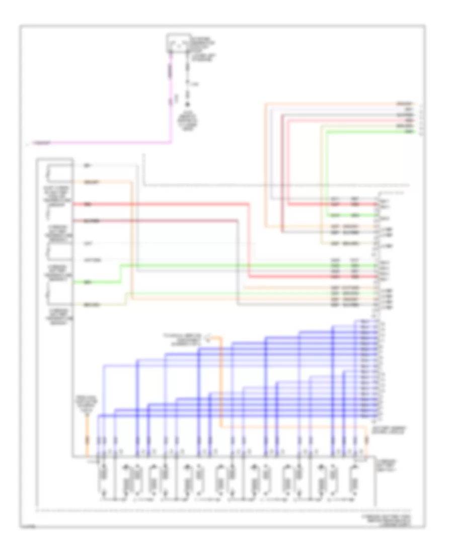
2.4L VIN R, Hybrid System Wiring Diagram (1 of 4) for Chevrolet Malibu LT 2014
List of elements for 2.4L VIN R, Hybrid System Wiring Diagram (1 of 4) for Chevrolet Malibu LT 2014:
- (between x110 & left headlamp)
- (left center engine compt)
- (left center engine compt) j126
- (left center engine nca compt) j127
- Acc wkup serial data
- Apm fuse 175a
- Auto disconnect ctrl
- Auxiliary transmission fluid pump relay
- Brake pedal position sensor
- Brk pos snsr 5
- Brk pos snsr low
- Brk pos snsr sig
- Computer data lines system
- Coolant pump relay coil control
- Driver motor control module 1
- Hot at all times
- Hot w/ engine controls ignition relay energized
- Hybrid/ev battery pack (behind rear seats in luggage compt)
- Hybrid/ev powertrain control module
- J121 (between throttle body breakout & ecm branch)
- J122 (on ecm x2 nca breakout)
- J123 (body harness near underhood fuse block)
- J124
- J128
- J129
- Nca
- Pnk
- Red
- Resolver cosine signal drain wire
- Resolver motor drain wire
- Resolver mtr positive
- Resolver signal 1
- Resolver signal 2
- Resolver signal 3
- Resolver signal 4
- Resolver sine signal drain wire
- Starter/generator
- Starter/generator control module
- Three phase motor temp drain wire
- Three phase motor temp low ref
- Three phase motor temp sig
- Trans aux pump bas+ fuse 30a
- Trns aux oil pump
- U phase
- Underhood fuse block (left side of battery)
- V phase
- W phase
- X10
- X115
- X210
2.4L VIN R, Hybrid System Wiring Diagram (2 of 4) for Chevrolet Malibu LT 2014
List of elements for 2.4L VIN R, Hybrid System Wiring Diagram (2 of 4) for Chevrolet Malibu LT 2014:
- (top of transmission) auxiliary transmission fluid pump
- 115v+
- 115v-
- Acc wakeup sig
- Batt pos volt
- Batt positive
- Batt positive voltage
- Battery energy control module
- Battery positive
- Bpim batt fuse 7.5a
- Bpim fuse 15a
- Bpim ign fuse 7.5a
- Can bus
- Computer data lines system
- Coolant temp snsr sig
- Current snsr low
- Current snsr sig
- Current snsr sply
- Fan spd sig (1)
- Fan spd sig (2)
- Fan spd snsr
- Fan speed snsr
- From hybrid/ev battery section 2 (diagram 4 of 4)
- G122 (rear of engine on cylinder head)
- G401 (left rear wheel well in luggage compt)
- Ground
- High speed gmlan
- High voltage relay
- Hot at all times
- Hot w/ engine controls ignition relay energized
- Hot w/ ignition main relay energized
- Hybrid/ev battery pack (behind rear seats in luggage compt)
- Hybrid/ev battery pack cable cover
- Hybrid/ev battery pack cooling fan (under right rear shelf)
- Hybrid/ev battery pack current sensor
- Hybrid/ev battery pre-charge resistor
- Hybrid/ev powertrain control module
- Interlock loop lo ref
- J120
- J401
- J402
- Logic
- Loop signal
- Main contactor
- Mgu cool pump fuse 10a
- Nca
- Pnk
- Pre-charge contactor
- Pre-charge relay
- Red
- Reference
- Run/crank ign 1
- Run/crank ignition 1
- Serial data (+)
- Serial data (-)
- Serial data accessory wakeup
- Snsr low reference
- Sply volt fan spd sig (1)
- Starter/ generator coolant pump relay
- Starter/generator control module
- Starter/generator coolant temperature sensor (right front side of engine compt)
- To hybrid/ev battery section 1 (diagram 3 of 4)
- Underhood fuse block (left side of battery)
- X115
- X150
2.4L VIN R, Hybrid System Wiring Diagram (3 of 4) for Chevrolet Malibu LT 2014
List of elements for 2.4L VIN R, Hybrid System Wiring Diagram (3 of 4) for Chevrolet Malibu LT 2014:
- Battery energy control module
- From main contactor (diagram 2 of 4)
- G122 (rear of engine on cylinder head)
- Hybrid/ev battery pack (behind rear seats in luggage compt)
- Hybrid/ev battery section 1
- Hybrid/ev battery temperature sensor 1
- Hybrid/ev battery temperature sensor 2
- Hybrid/ev battery temperature sensor 3
- Inlet hybrid/ ev battery pack air temperature sensor
- J120
- Lo ref
- Red
- Sig 1
- Sig 2
- Sig 3
- Sig 4
- Sig 5
- Sig 6
- Sig 7
- Starter/ generator coolant pump (lower left of engine)
- To manual service disconnect (diagram 4 of 4)
- X115
2.4L VIN R, Hybrid System Wiring Diagram (4 of 4) for Chevrolet Malibu LT 2014
List of elements for 2.4L VIN R, Hybrid System Wiring Diagram (4 of 4) for Chevrolet Malibu LT 2014:
- 125a
- Battery energy control module
- From hybrid/ev battery section 1 (diagram 3 of 4)
- Hybrid/ev battery pack (behind rear seats in luggage compt)
- Hybrid/ev battery section 2
- Hybrid/ev battery temperature sensor 4
- Hybrid/ev battery temperature sensor 5
- Hybrid/ev battery temperature sensor 6
- Manual service disconnect
- Red
- To hybrid/ev battery pack current sensor (diagram 2 of 4)
2.5L VIN L
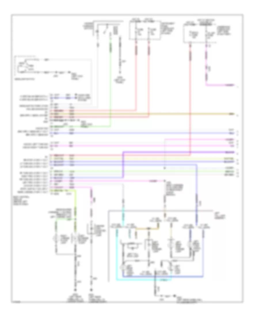
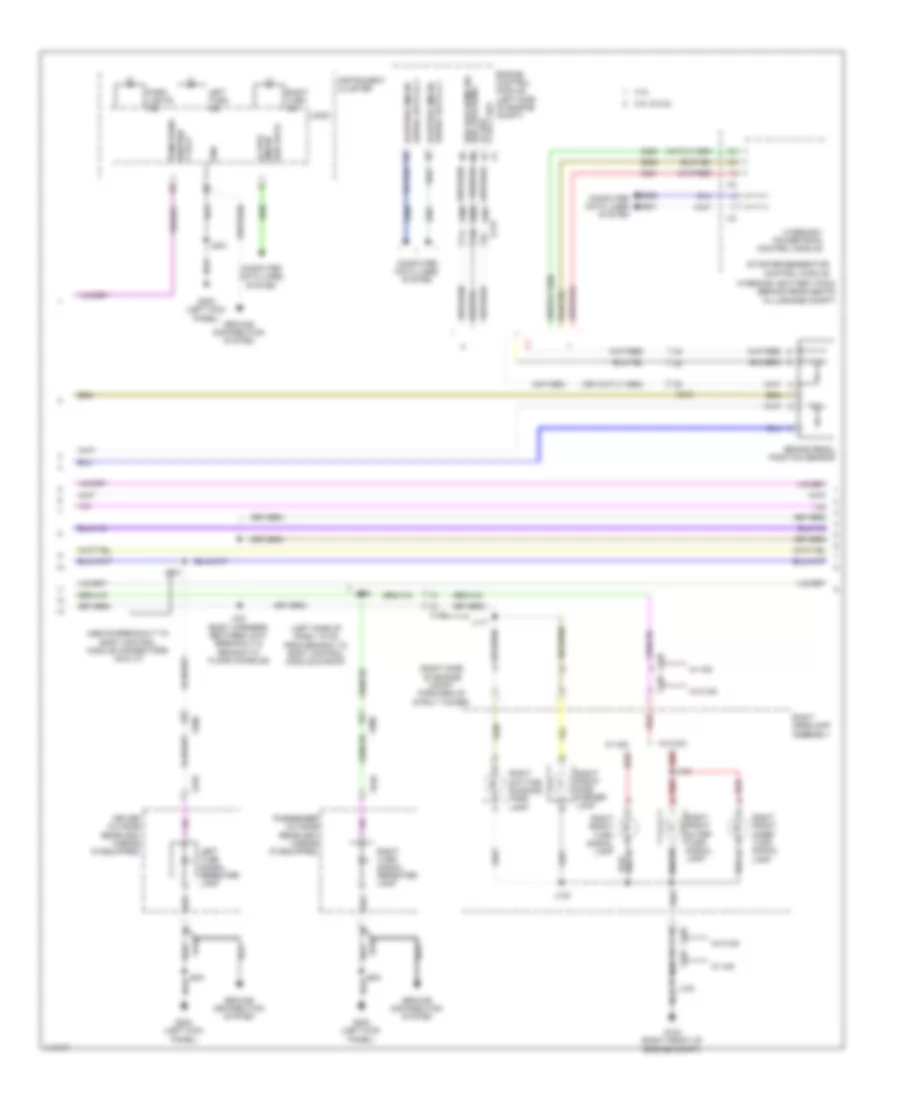
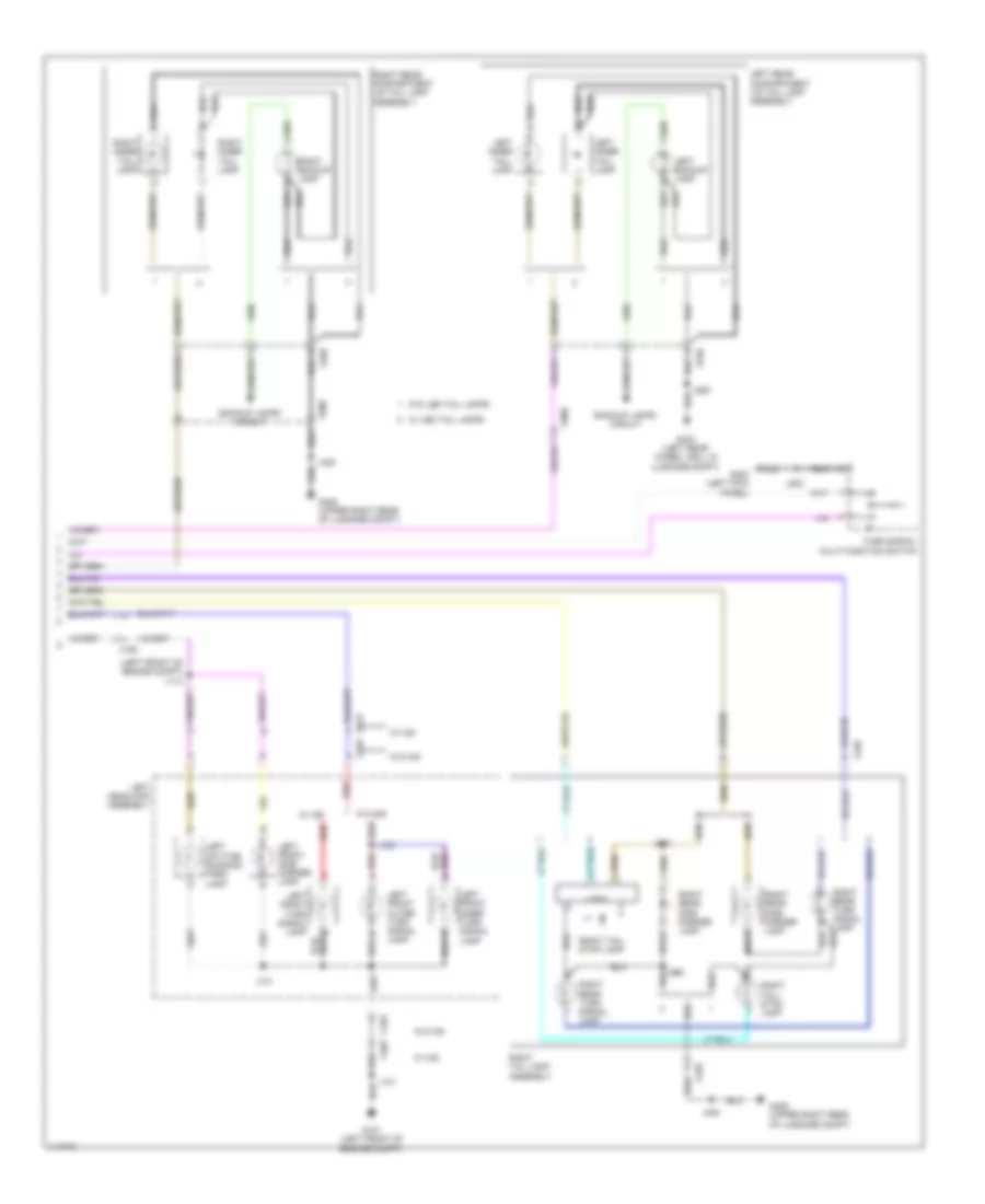
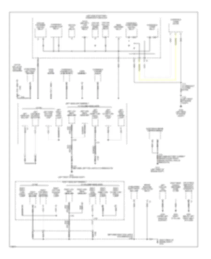
2.5L VIN L, Engine Performance Wiring Diagram (1 of 6) for Chevrolet Malibu LT 2014
List of elements for 2.5L VIN L, Engine Performance Wiring Diagram (1 of 6) for Chevrolet Malibu LT 2014:
- (not used)
- (or 3200)
- (or 3201)
- (or 4325)
- 2.0l vin x
- 2.5l vin l
- 5v ref
- A/c compressor clutch rly ctrl
- A/c press sens 5v ref
- A/c refrigerant press sens lo ref
- A/c refrigerant pressure sens sig
- A/c refrigerant pressure sensor (right side of a/c condenser)
- Accessory wakeup serial data
- Air conditioning system
- Air pressure sig
- App lo ref
- App low ref
- App sens sig (1)
- App sens sig (2)
- Batt pos vol
- Brake pedal position sensor
- Brk pos sen sig
- Brk pos sens 5v ref
- Brk pos sens low ref
- Check engine ind ctrl
- Computer data lines system
- Coolant temp sens sig (2)
- Cooling fans system
- Cruise control system
- Cruise\etc\tcc brk sig
- Engine control module (ecm) (left side of engine compt)
- Evap canister vent sol ctrl
- Evaporative emission vent solenoid valve (right side of fuel tank)
- Fuel level sens lo ref
- Fuel level sens sig
- Fuel line press sens 5v ref
- Fuel line pressure sens lo ref
- Fuel line pressure sens sig
- Fuel pressure sensor (right side of fuel tank)
- Fuel pump controller data out sig
- Fuel tank pressure sens sig
- Fuel tank pressure sensor (top of fuel tank)
- Hi spd cooling fan rly ctrl
- Hi spd gmlan serial data (+)
- Hi spd gmlan serial data (-)
- Low ref
- Low speed cooling fan rly ctrl
- Main relay fused sply
- Powertrain main rly fused sply (1)
- Powertrain rly coil ctrl
- Pre-throttle air press temp sig
- Reaction pump rly coil ctrl
- Reaction solenoid rly coil ctrl
- Run/crank ign 1 vol
- Sens 2 low ref
- Starter enable rly ctrl
- Starting/ charging system
- Starting/charging system
- Turbo charger boost/intake air temperature sensor (2.0l vin x) (engine compt integral to throttle body)
- Underhood fuse block (left side of battery) x3
- X115
- X117
- X210
- X350
2.5L VIN L, Engine Performance Wiring Diagram (2 of 6) for Chevrolet Malibu LT 2014
List of elements for 2.5L VIN L, Engine Performance Wiring Diagram (2 of 6) for Chevrolet Malibu LT 2014:
- (above accelerator pedal) accelerator pedal position sensor
- 2.0l vin x
- 2.5l vin l
- Batt pos volt
- Computer data lines system
- From engine controls ignition relay (diagram 3 of 6)
- Fuel level sensor
- Fuel pump
- Fuel pump & level sensor assembly (top of fuel tank)
- Fuel pump driver control module (right side of luggage compt)
- G122 (rear of engine on cylinder head)
- G405 (upper right rear of luggage compt)
- Gmlan ser data (+)
- Gmlan ser data (-)
- Gnd
- Hot at all times
- Ignition 1 volt
- J120
- J406 (w/ vri)
- J434 (body harness, in branch to x420)
- J435
- J457 (right rear wheelwell)
- Low ref
- Nca
- Out sig
- Sair sol fuse 15a
- Sec air pump fuse 50a
- Secondary air injection pump (2.5l: right side of engine)
- Secondary air injection pump relay (california emission system)
- Secondary air injection solenoid valve relay (california emission system)
- Shield extension
- Sply volt
- Underhood fuse block (left side of battery)
- Wakeup serial data
- X114
- X115
- X210
- X350
2.5L VIN L, Engine Performance Wiring Diagram (3 of 6) for Chevrolet Malibu LT 2014
List of elements for 2.5L VIN L, Engine Performance Wiring Diagram (3 of 6) for Chevrolet Malibu LT 2014:
- 2.0l vin x
- 2.5l vin l
- Coil odd fuse 15a
- Cps fuse 10a
- Ecm batt fuse 5a
- Ecm fuse 20a
- Ecm ign fuse 5a
- Emission 1 fuse 10a
- Emission 2 fuse 10a
- Engine controls ignition relay
- Engine coolant temperature sensor
- Engine oil pressure sensor (right side of engine)
- Exhaust camshaft position actuator solenoid valve (top front of engine)
- Fscm fuse 20a
- G101 (left front of engine compt)
- G122 (rear of engine on cylinder head)
- High pressure fuel pump (top rear of engine)
- Hot at all times
- Hot in run or start
- Ignition main relay
- J120
- Mil ign fuse 5a
- Red
- Secondary air injection solenoid valve (california emission system) (2.5l: top rear of engine)
- Tc fsc ign fuse 7.5a
- To secondary air injection pump relay (diagram 2 of 6)
- Underhood fuse block (left side of battery)
2.5L VIN L, Engine Performance Wiring Diagram (4 of 6) for Chevrolet Malibu LT 2014
List of elements for 2.5L VIN L, Engine Performance Wiring Diagram (4 of 6) for Chevrolet Malibu LT 2014:
- (near exhaust camshaft position sensor breakout)
- (on camshaft cover)
- 5v ref
- Actuator hi ctrl
- Actuator low ctrl
- Camshaft pos intake
- Computer data lines system
- Crankshaft 60x sens volt
- Crankshaft sens sig
- Ctrl cylinder 1
- Ctrl cylinder 2
- Ctrl cylinder 3
- Ctrl cylinder 4
- Cylinder head engine oil pressure sensor (2.5l vin l) (engine compt rear of engine)
- Data
- Driver information center (dic)
- Ect sens sig
- Engine control module (ecm) (left side of engine compt)
- Exhaust sens (1)
- Exhaust sol (1)
- Fuel ind
- G122 (rear of engine on cylinder head)
- G203 (left kick panel)
- Gnd
- Ic ctrl (1)
- Ic ctrl (2)
- Ic ctrl (3)
- Ic ctrl (4)
- Ign
- Ignition coil 1
- Ignition coil 2
- Ignition coil 3
- Ignition coil 4
- Instrument cluster
- Intake sol (1)
- J103 (between intake camshaft position sensor & evaporative emission purge solenoid valve breakouts)
- J106
- J108 (near x160 breakout)
- J122
- J203
- Logic
- Low ref
- Low ref bank 1
- Malfunction ind lamp (mil)
- Nca
- Oil level ind lamp
- Oil press sens sig
- Red
- Sens lo ref
- Serial gmlan
- Sig
- Spark plug
- Sply volt
- X210
2.5L VIN L, Engine Performance Wiring Diagram (5 of 6) for Chevrolet Malibu LT 2014
List of elements for 2.5L VIN L, Engine Performance Wiring Diagram (5 of 6) for Chevrolet Malibu LT 2014:
- (2.0l: top right rear of engine) (2.5l: top right front of engine) evaporative emission purge solenoid valve
- (above a/c compressor) (2.0l vin x) turbocharger bypass solenoid valve
- (left side of engine) engine oil pressure control solenoid valve
- (top right of engine)
- (top right of engine) fuel injector 2
- (top right of engine) fuel injector 3
- (top right of engine) fuel injector 4
- Battery fuse block (on battery)
- Crankshaft position sensor (right rear of engine)
- Engine control module (ecm) (left side of engine compt)
- Engine oil level switch (right side of oil pan)
- Exhaust camshaft position sensor (front of cylinder head)
- Fuel injector 1
- Fuse 250a
- G121 (on engine rear of a/c compressor)
- Gnd
- Hot at all times
- Intake camshaft position actuator solenoid valve (top front of engine)
- Intake camshaft position sensor (front of cylinder head)
- J121
- Low ref
- Red
- Sply cylinder 1
- Sply cylinder 2
- Sply cylinder 3
- Sply cylinder 4
- Step cam a ctrl
- Step cam b ctrl
- Turbocharger wastegate solenoid valve (2.0l vin x) (above a/c compressor)
- X160
2.5L VIN L, Engine Performance Wiring Diagram (6 of 6) for Chevrolet Malibu LT 2014
List of elements for 2.5L VIN L, Engine Performance Wiring Diagram (6 of 6) for Chevrolet Malibu LT 2014:
- (above catalytic converter) heated oxygen sensor 1
- (below catalytic converter) heated oxygen sensor 2
- (on upper air cleaner assembly) multi-function intake air sensor
- (or 3630)
- 2.0l vin x
- 2.5l vin l
- 5v ref
- 5v ref fuel rail press sens sig
- Air temp low ref
- Air temp sens sig
- Bank 1 sens (1)
- Bank 1 sens (2)
- Charge ind ctrl
- Ctrl bank (1)
- Current sens sig
- Engine control module (ecm) (left side of engine compt)
- Fuel rail pressure sensor (left side of engine)
- G121 (on engine rear of a/c compressor)
- Generator field
- Gnd
- Hi sig bank 1 sens (1)
- Hi sig bank 1 sens (2)
- J107 (between exhaust camshaft position sensor and g122)
- J121
- Knock sens
- Knock sens sig
- Knock sens transmission park/ neutral signal (1) command sig
- Knock sensor 1 (right side of engine)
- Knock sensor 2 (right side of engine)
- Low ref
- Maf sens sig
- Manifold absolute pressure sensor (near throttle body)
- Map low ref
- Map sens sig
- Nca
- Oil level sw sig
- Purge sol ctrl
- Ref bank (1)
- Sens sig
- Sens sig bank (1)
- Sply volt
- Starting/charging system
- Tac close
- Tac open
- Throttle body (right side of engine)
- Tp sens sig waste gate
- Transmissions system
- X160
EXTERIOR LIGHTS
Backup Lamps Wiring Diagram for Chevrolet Malibu LT 2014
List of elements for Backup Lamps Wiring Diagram for Chevrolet Malibu LT 2014:
- (left rear wheel well in luggage compt)
- (upper right rear of luggage compt)
- 2.0l
- 2.5l & 2.4l
- Automatic transmission assembly
- Backup lamp sply volt
- Backup lp sply volt
- Batt pos volt
- Body control module (behind left side of dash)
- Computer data lines system
- Control solenoid valve assembly
- Engine control module (ecm) (left side of engine compt)
- Fuse 15a
- G403
- G405
- Gnd
- Ground distribution system
- Hot at all times
- Inside rearview mirror (isrvm) (if equipped)
- Instrument panel fuse block (left side of dash)
- J318 (body harness, 8 cm forward of rear shelf)
- J405
- J920
- Left backup lamp
- Left inner tail- lamp
- Left rear compartment lid tail lamp assembly
- Logic
- Rearview camera (above rear license plate)
- Right backup lamp
- Right inner tail- lamp
- Right rear compartment lid tail lamp assembly
- Serial data (+)
- Serial data (+) high speed gmlan
- Serial data (-)
- Serial data (-) high speed gmlan
- Sig a
- Sig b
- Sig c
- Sig p
- Transmission control module (tcm)
- Transmission internal mode switch
- W/ led tail- lamps
- W/o led tail- lamps
- Wake up sig
- X2 a
- X2 f
- X415
- X900
- X910
- X920
Exterior Lamps Wiring Diagram (1 of 3) for Chevrolet Malibu LT 2014
List of elements for Exterior Lamps Wiring Diagram (1 of 3) for Chevrolet Malibu LT 2014:
- (rear bumper harness, 11 cm from breakout to left license lamp) j487
- Auto
- Bcm 6 fuse 15a
- Body control module (behind left side of dash)
- Center high mounted stop lamp
- Computer data lines system
- Fuse 15a
- G203 (left kick panel)
- G305 (left kick panel)
- G403 (left rear wheelwell in luggage compt)
- Gnd
- Haz led dimming sig
- Haz sw left turn sig
- Haz sw right turn sig
- Haz sw sig
- Hazard switch
- Hazard warning switch
- Head
- Headlamp sw park lp sig
- Headlamp switch
- Hi spd gmlan ser data (+)
- Hi spd gmlan ser data (-)
- Hot at all times
- Hot w/ ignition main relay energized
- Instrument panel fuse block (left side of dash)
- J201
- J203
- J326 (body harness, 37 cm forward of rear shelf & roof branch)
- J403
- J920
- J930
- J950
- Left license plate lamp
- Left prk lp sply volt
- Left rear side marker lamp
- Left rear turn signal lamp
- Left tail lamp assembly
- Left tail/ stop lamp
- Lf turn sig lp sply volt
- Logic
- Lr stop lp sply volt
- Lr turn sig lp sply volt
- Mil ign fuse 5a
- Off
- Park
- Rear license lp sply volt
- Rf turn sig lp sply volt
- Right license plate lamp
- Right prk lp sply volt
- Rr stop lp sply volt
- Rr turn sig lp sply volt
- Stop lamp rly coil sply
- Underhood fuse block (left side of battery)
- W/ led tail lamps
- W/o led tail lamps
- X210
- X410
- X415
- X900
Exterior Lamps Wiring Diagram (2 of 3) for Chevrolet Malibu LT 2014
List of elements for Exterior Lamps Wiring Diagram (2 of 3) for Chevrolet Malibu LT 2014:
- (above breakout to body control module connectors x6 & x7)
- (left side of dash, 18 cm from branch to body control module & roof)
- (right side of engine compt forward of strut tower)
- 2.0l & 2.5l
- 2.4l
- 5 volt ref lo ref brk posi sens
- Brake pedal position sensor
- Brk pos sens sig
- Computer data lines system
- Driver outside rearview mirror (if equipped)
- Engine control module (left side of engine compt)
- G102 (right front of engine compt)
- G203 (left kick panel)
- Gmlan lo spd
- Gnd
- Ground distribution system
- Hybrid/ev battery pack (behind rear seats in luggage compt)
- Hybrid/ev powertrain control module
- Instrument cluster
- J102
- J117
- J132
- J134
- J203
- J218
- J219
- J321 (body harness, between x210 breakout & branch to floor console)
- Left turn ind
- Left turn signal repeater lamp
- Logic
- Park lights ind
- Passenger outside rearview mirror (if equipped)
- Red
- Right daytime running/ park lamp
- Right front inner turn signal lamp
- Right front outer turn signal lamp
- Right front side marker lamp
- Right front turn signal lamp
- Right headlamp assembly
- Right turn ind
- Right turn signal repeater lamp
- Run/crank ignition 1 volt
- Ser data
- Serial data (+) 1 hi speed gmlan
- Serial data (-) 1 hi speed gmlan
- Starter/generator control module
- W/ hid
- W/o hid
- X115
- X120
- X150
- X210
- X500
- X510
- X600
- X610
Exterior Lamps Wiring Diagram (3 of 3) for Chevrolet Malibu LT 2014
List of elements for Exterior Lamps Wiring Diagram (3 of 3) for Chevrolet Malibu LT 2014:
- (left front of engine compt) j113
- Backup lamps circuit
- G101 (left front of engine compt)
- G203 (left kick panel)
- G403 (left rear wheel well in luggage compt)
- G405 (upper right rear of luggage compt)
- J101
- J131
- J133
- J203
- J405
- J920
- J940
- J960
- Left backup lamp
- Left daytime running/ park lamp
- Left front inner turn signal lamp
- Left front outer turn signal lamp
- Left front side marker lamp
- Left front turn signal lamp
- Left headlamp assembly
- Left inner tail- lamp
- Left rear compartment lid tail lamp assembly
- Logic
- Red
- Right backup lamp
- Right inner tail- lamp
- Right rear compartment lid tail lamp assembly
- Right rear side marker lamp
- Right rear turn signal lamp
- Right tail lamp assembly
- Right tail/ stop lamp
- Turn signal/ multi-function switch
- W/ hid
- W/ led tail lamps
- W/o hid
- W/o led tail lamps
- X110
- X150
- X420
- X900
- X910
- X920
GROUND DISTRIBUTION
Ground Distribution Wiring Diagram (1 of 6) for Chevrolet Malibu LT 2014
List of elements for Ground Distribution Wiring Diagram (1 of 6) for Chevrolet Malibu LT 2014:
- (between right fog lamp & g102 breakouts) j102
- (if equipped) left front fog lamp
- (if equipped) right front fog lamp
- (left side of battery) underhood fuse block
- (right front of engine compt) g102
- 2.4l
- 87a
- Active grille air shutter actuator
- Brake booster pump motor relay
- Child security lock disable relay
- Cooling fan high speed relay
- Cooling fan low speed relay
- Cooling fan speed control relay
- Electronic brake control module
- G101 (left front of engine compt)
- G106 (upper left radiator support)
- G109 (left rear of engine compt)
- G110 (left front of engine compt)
- G303 (below left front seat on floor)
- G404 (right "c" pillar)
- Hood ajar switch
- Horn assembly
- Ignition main relay
- Inflatable restraint sensing & diagnostic module
- J110 (between battery current sensor & electronic brake control module breakouts)
- J114 (at breakout to wiper motor)
- J129
- J130
- J131
- J132
- Left cooling fan motor
- Left front inner turn signal lamp
- Left front outer turn signal lamp
- Left front side marker lamp
- Left front turn signal lamp
- Left headlamp assembly
- Left headlamp ballast
- Left high beam headlamp
- Left high beam solenoid actuator
- Left low beam headlamp
- Left park/ daytime running lamp
- Of engine compt)
- Rear defogger relay
- Right daytime running/ park lamp
- Right front inner turn signal lamp
- Right front outer turn signal lamp
- Right front side marker lamp
- Right front turn signal lamp
- Right headlamp assembly
- Right headlamp ballast
- Right high beam headlamp
- Right high beam solenoid actuator
- Right low beam headlamp
- Right rear window defogger noise filter
- W/ halogen headlamps
- W/ hid
- Windshield washer fluid level switch
- Windshield washer pump
- Windshield washer pump relay
- Windshield wiper motor
- Windshield wiper relay
- Windshield wiper speed control relay
- X110
- X120
- X125
Ground Distribution Wiring Diagram (2 of 6) for Chevrolet Malibu LT 2014
List of elements for Ground Distribution Wiring Diagram (2 of 6) for Chevrolet Malibu LT 2014:
- (2.4l) cylinder 1/2 secondary air injection solenoid valve
- (2.4l) cylinder 3/4 secondary air injection solenoid valve
- (2.4l) mass air flow/ intake air temperature sensor
- (2.5l & 2.0l) engine oil level switch
- (2.5l & 2.0l) multi-function intake air sensor
- (2.5l) secondary air injection solenoid valve
- (hybrid) auxiliary transmission fluid pump
- (hybrid) heater coolant pump
- (hybrid) starter/ generator coolant pump
- (if equipped) collision alert indicators
- (if equipped) inside rearview mirror
- (if equipped) starter pinion solenoid actuator relay
- (left side of battery) underhood fuse block
- (manual a/c) ambient light/ sunload sensor
- (w/ automatic electronic controlled) multi-axis acceleration sensor
- (w/ automatic electronic controlled) steering wheel angle sensor
- (w/ emission system) secondary air injection pump
- (w/ keyless engine start) ignition mode switch
- (w/ lane departure warning) frontview camera module
- 2.0l
- 2.4l
- A/c compressor clutch
- Automatic transmission assembly
- Body control module
- Brake fluid level switch
- Control solenoid valve assembly
- Data link connector
- Engine control module
- Except 2.0l
- Except 2.4l
- From splice j504 (diagram 3 of 6)
- From splice j604 (diagram 3 of 6)
- G121 (on engine rear of a/c compressor)
- G122 (rear of engine on cylinder head)
- G203 (left kick panel)
- Headlamp switch
- Hvac control module
- Ignition coil 1
- Ignition coil 2
- Ignition coil 3
- Ignition coil 4
- Instrument cluster
- J120 (between fuse block- underhood branch & ecm branch)
- J121 (between throttle body breakout & ecm branch)
- J122 (on ecm x2 breakout)
- J203 (between data link connector & jx200 breakouts)
- J304 (base of left "a" pillar between x210 breakout & branch to console)
- J706 (left rear door harness, in left rear door)
- J804
- Left rear door latch assembly
- Left rear exterior door handle assembly
- Left rear exterior door handle switch
- Left rear window switch
- Logic
- Power steering control module
- Right rear door latch assembly
- Right rear exterior door handle assembly
- Right rear exterior door handle switch
- Starter relay
- Transmission control module (tcm)
- Transmission shift lever position indicator
- Turn signal/ multi-function switch
- X215
- X300
- X500
- X600
- X700
- X800
Ground Distribution Wiring Diagram (3 of 6) for Chevrolet Malibu LT 2014
List of elements for Ground Distribution Wiring Diagram (3 of 6) for Chevrolet Malibu LT 2014:
- (not used)
- (w/ keyless engine start) keyless entry control module
- (w/ right power control lumbar seat) passenger seat lumbar support pump
- (w/ right power control lumbar seat) passenger seat lumbar support switch
- (w/ right power control lumbar seat) passenger seat lumbar support valve assembly
- 2-way power seat
- 8-way power seat
- Blower motor control module
- Center console accessory power receptacle
- Driver door accent lamp
- Driver door handle accent lamp
- Driver door latch assembly
- Driver door lock switch
- Driver door pocket flood lamp
- Driver exterior door handle assembly
- Driver exterior door handle switch
- Driver outside rearview mirror
- Driver outside rearview mirror glass
- Driver side object detection indicator
- G302 (right kick panel)
- Instrument panel accessory power receptacle
- Instrument panel compartment lamp
- J204 (between x215 & instrument compartment lamp breakouts)
- J302 (right "a" pillar between x221 & g302 breakouts)
- J313 (passenger seat harness, in seat back)
- J506 (driver door harness, on breakout to flood lamp)
- J604 (passenger door lamp harness, on breakout to door handle)
- Lamp harness, on breakout to flood lamp)
- Left turn signal repeater lamp
- Logic
- Outside rearview mirror switch
- Passenger door accent lamp
- Passenger door handle accent lamp
- Passenger door latch assembly
- Passenger door lock switch
- Passenger door pocket flood lamp
- Passenger exterior door handle assembly
- Passenger exterior door handle switch
- Passenger instrument panel air bag
- Passenger outside rearview mirror
- Passenger outside rearview mirror glass
- Passenger presence module
- Passenger seat adjuster switch
- Passenger side object detection indicator
- Passenger window switch
- Right rear seat side air bag
- Right rear window switch
- Right turn signal repeater lamp
- To splice j304 (diagram 2 of 6)
- X205
- X300
- X320
- X322
- X505
- X600
- X605
- X800
Ground Distribution Wiring Diagram (4 of 6) for Chevrolet Malibu LT 2014
List of elements for Ground Distribution Wiring Diagram (4 of 6) for Chevrolet Malibu LT 2014:
- (not used)
- (on battery) battery fuse block
- Accessory dc/ ac power inverter module
- Battery
- Battery current sensor
- Battery sensor module
- Body control module
- Data link connector
- Dual battery control module
- From splice j305 (diagram 5 of 6)
- G100 (near battery)
- G103 (near starter/ generator)
- G305 (left kick panel)
- Hazard warning switch
- Horn switch
- Instrument panel fuse block (left side of dash)
- Instrument panel malfunction switch 2
- J201 (between headlamp switch & jx200 breakouts)
- Left instrument panel accent lamp
- Left middle instrument panel accent lamp
- Left steering wheel controls switch
- Park position switch
- Pnk
- Rear compartment lid unlatch relay
- Red
- Retained accessory power relay
- Right instrument panel accent lamp
- Right steering wheel controls switch
- Steering wheel air bag coil (center of steering wheel)
- Transmission manual shift switch
- Transmission shift lever
- W/ engine start/stop system
- W/o engine start/stop system
- X300
Ground Distribution Wiring Diagram (5 of 6) for Chevrolet Malibu LT 2014
List of elements for Ground Distribution Wiring Diagram (5 of 6) for Chevrolet Malibu LT 2014:
- (2.0l & 2.5l) fuel pump driver control module
- (2.4l) chassis control module
- (if equipped) audio amplifier
- (if equipped) driver seat adjuster switch
- (if equipped) driver seat lumbar support pump
- (if equipped) driver seat lumbar support switch
- (if equipped) driver seat lumbar support valve assembly
- (if equipped) sunroof motor
- (w/ memory) seat memory control module (w/o memory) driver seat heating control module
- (w/ rearview camera) info display module
- 2-way power seat
- 8-way power seat
- Auxiliary audio input
- Body control module
- Driver window motor
- Driver window switch
- G205 (right kick panel)
- G405 (upper right rear of luggage compt)
- Harness, on breakout to x510)
- Hvac control module
- Hvac controls
- J202 (between x205 & instrument compt lamp breakouts)
- J314 (driver seat harness, under passenger seat)
- J317 (right front passenger compt near a pillar)
- J405 (body harness, in branch to x420)
- J960
- Left rear seat side air bag
- Left rear window switch
- Logic
- Nca
- Of driver seat)
- Pillar between x210 breakout & branch to console)
- Radio
- Radio controls
- Right backup lamp
- Right inner tail lamp
- Right rear compartment lid tail lamp assembly
- Right rear side marker lamp
- Right rear turn signal lamp
- Right tail lamp assembly
- Right tail/ stop lamp
- Telematics communication interface control module
- To ground g305 (diagram 4 of 6)
- W/ led tail lamps
- W/ memory
- W/ power operated window
- W/ tcu
- W/o led tail lamps
- W/o memory
- W/o power operated window
- W/o tcu
- X300
- X310
- X321
- X500
- X700
- X900
Ground Distribution Wiring Diagram (6 of 6) for Chevrolet Malibu LT 2014
List of elements for Ground Distribution Wiring Diagram (6 of 6) for Chevrolet Malibu LT 2014:
- & lamps)
- (hybrid) hybrid/ev battery pack cooling fan
- (if equipped) garage door opener
- (if equipped) left sunshade
- (if equipped) rear parking assist control module
- (if equipped) rearview camera
- (if equipped) right sunshade
- (if equipped) sunroof switch
- (if equipped) sunroof tilt switch
- Auxiliary battery (w/ engine start/stop)
- Center console flood lamp
- Center high mounted stop lamp
- Dome lamp switch
- G401 (left rear wheel well in luggage compt)
- G403 (left rear wheel well in luggage compt)
- J309 (headliner harness, left rear corner of roof)
- J401 (body harness, between rear shelf & roof branch breakouts)
- J403 (body harness, between g401 & g403 breakouts)
- J418 (left rear of vehicle)
- J486
- J920 (right side of rear compt lid, between x920 & lamps)
- J950
- Left backup lamp
- Left front overhead console dome/ reading lamps
- Left inner tail lamp
- Left license plate lamp
- Left rear compartment lid tail lamp assembly
- Left rear side marker lamp
- Left rear turn signal lamp
- Left side object sensor module
- Left sunshade mirror lamp
- Left tail lamp assembly
- Left tail/ stop lamp
- Logic
- Nca
- Passenger air bag disable indicator
- Rear compartment courtesy lamp
- Rear compartment lid latch
- Rear compartment lid unlatch switch
- Rear dome/ reading lamps
- Right front overhead console dome/ reading lamps
- Right license plate lamp
- Right side object sensor module
- Right sunshade mirror lamp
- W/ led tail lamps
- W/ parking assist
- W/0 led tail lamps
- W/o parking assist
- X400
- X415
- X900
HEADLIGHTS
Headlights Wiring Diagram, with High Intensity Discharge (1 of 2) for Chevrolet Malibu LT 2014
List of elements for Headlights Wiring Diagram, with High Intensity Discharge (1 of 2) for Chevrolet Malibu LT 2014:
- (center of dash) hvac control module
- (left front of engine compt) g101
- (right front of engine compt) g102
- Ambient light/ sunload sensor (top center of dash)
- Ambient sens sig
- Automatic a/c
- Battery fuse block (on battery)
- Body control module (behind left side of dash)
- Computer data lines system
- Exterior lights system
- Flash
- Fog lamp fuse 15a
- Fog lamp rly ctrl
- Front fog lamp relay
- Fuse 200a
- G203 (left kick panel)
- Gmlan ser data (+)
- Gmlan ser data (-)
- Gnd
- Ground distribution system
- Hdlp dimmer sw hi beam sig x3
- Hdlp hi beam rly ctrl
- Hdlp lw beam rly ctrl
- Hdlp off sig ctrl
- Hdlp sw flash
- Hdlp sw on sig
- Hdlp sw park lamp sig
- Headlamp high beam relay
- Headlamp low beam relay
- High
- Hot at all times
- J101
- J102
- J131
- J132
- J203
- Left headlamp assembly
- Left headlamp ballast
- Left high beam solenoid actuator
- Left low beam headlamp
- Left park/ daytime running lamp
- Lh drl sply volt
- Lighting ctrl sw ref
- Lighting ctrl sw sig
- Low
- Low ref
- Lt hi beam fuse 10a
- Lt hid fuse 15a
- Manual a/c
- Nca
- Park brk sw sig
- Red
- Rh drl sply volt
- Right headlamp assembly
- Right headlamp ballast
- Right high beam solenoid actuator
- Right low beam headlamp
- Right park/daytime running lamp
- Rt hi beam fuse 10a
- Rt hid fuse 15a
- To pass sig
- Turn signal/ multi-function switch
- Underhood fuse block (left side of battery)
- X110
- X120
- X150
- X215
Headlights Wiring Diagram, with High Intensity Discharge (2 of 2) for Chevrolet Malibu LT 2014
List of elements for Headlights Wiring Diagram, with High Intensity Discharge (2 of 2) for Chevrolet Malibu LT 2014:
- Auto
- Computer data lines system
- Cruise control system
- Dimmer switch
- Driver information center display
- Fog lamp switch
- Front fog lamp ind
- Fuse 15a
- G101 (left front of engine compt)
- G102 (right front of engine compt)
- G203 (left kick panel)
- Head
- Headlamp switch
- High beam ind
- Hot at all times
- Instrument cluster
- Instrument panel fuse block (left side of dash)
- Interior lights system
- J101
- J102
- J203
- J212 (on breakout to body control module connector x3)
- Left front fog lamp
- Logic
- Low spd gmlan ser data
- Off
- Off head
- Park
- Park brake switch (mounted to shift lever bezel)
- Right front fog lamp
- X210
Headlights Wiring Diagram, without High Intensity Discharge (1 of 2) for Chevrolet Malibu LT 2014
List of elements for Headlights Wiring Diagram, without High Intensity Discharge (1 of 2) for Chevrolet Malibu LT 2014:
- (left front of engine compt) g101
- Ambient light/ sunload sensor (top center of dash)
- Ambient sens sig
- Automatic a/c
- Battery fuse block (on battery)
- Body control module (behind left side of dash)
- Computer data lines system
- Flash
- Fog lamp fuse 15a
- Fog lamp rly ctrl
- Front fog lamp relay
- Fuse 200a x5
- G203 (left kick panel)
- Gmlan ser data (+)
- Gmlan ser data (-)
- Gnd
- Hdlp dimmer sw hi beam sig x3
- Hdlp hi beam rly ctrl
- Hdlp off sig ctrl
- Hdlp sw flash
- Hdlp sw on sig
- Hdlp sw park lp sig
- Headlamp high beam relay
- High
- Hot at all times
- Hvac control module (center of dash)
- J101
- J102
- J129
- J130
- J203
- Left headlamp assembly
- Left high beam headlamp
- Left low beam headlamp
- Lh low beam sply volt
- Lighting ctrl sw ref
- Lighting ctrl sw sig
- Low
- Low ref
- Lt hi beam fuse 10a
- Manual a/c
- Red
- Rh low beam sply volt
- Right headlamp assembly
- Right high beam headlamp
- Right low beam headlamp
- Rt hi beam fuse 10a
- To pass sig
- Turn signal/ multi-function switch
- Underhood fuse block (left side of battery)
- X110
- X120
- X150
- X215
Headlights Wiring Diagram, without High Intensity Discharge (2 of 2) for Chevrolet Malibu LT 2014
List of elements for Headlights Wiring Diagram, without High Intensity Discharge (2 of 2) for Chevrolet Malibu LT 2014:
- Auto
- Computer data lines system
- Cruise control system
- Dimmer switch
- Driver information center display
- Fog lamp switch
- Front fog lamp ind
- Fuse 15a
- G101 (left front of engine compt)
- G102 (right front of engine compt)
- G203 (left kick panel)
- Head
- Headlamp switch
- High beam ind
- Hot at all times
- Instrument cluster
- Instrument panel fuse block (left side of dash)
- Interior lights system
- J101
- J102
- J203
- J212 (on breakout to body control module connector x3)
- Left front fog lamp
- Logic
- Low spd gmlan ser data
- Off
- Off head
- Park
- Right front fog lamp
HORN
Horn Wiring Diagram for Chevrolet Malibu LT 2014
List of elements for Horn Wiring Diagram for Chevrolet Malibu LT 2014:
- (behind left side of dash) body control module (bcm)
- (left radiator support)
- Battery fuse block (on battery)
- Fuse 5 250a
- G101 (left front of engine compt)
- G305 (left kick panel)
- Ground distribution system
- Horn assembly
- Horn fuse 15a
- Horn relay
- Horn rly ctrl
- Horn sw sig
- Horn switch
- Hot at all times
- J101
- J201
- Pnk
- Red
- Right steering wheel control switch
- Steering wheel air bag coil
- Underhood fuse block (left side of battery)
INSTRUMENT CLUSTER
Instrument Cluster Wiring Diagram (1 of 2) for Chevrolet Malibu LT 2014
List of elements for Instrument Cluster Wiring Diagram (1 of 2) for Chevrolet Malibu LT 2014:
- 4wd
- Abs ind
- Air bag ind
- Ambient air temperature sensor (left side of lower grille)
- Battery pos volt
- Body control module (behind left side of dash)
- Brake warning ind lamp
- Bus 2 network
- Charge ind
- Computer data lines system
- Control coil rap relay
- Cruise ind
- Dim ctrl led ctrl
- Driver information center display
- Drv center menu sw sig
- Drv information sw sig drv lo ref
- Engine controls system
- Engine coolant temperature gauge
- Engine ind ctrl
- Front fog lamp ind
- Fuel gauge
- Fuse 5a
- G203 (left kick panel)
- Gnd
- Ground
- Ground distribution system
- Hi spd gmlan serial data + hi spd gmlan serial data -
- High beam ind
- Hot at all times
- Hot w/ ignition main relay energized
- Ign 1 volt
- Illumination ind
- Instrument cluster
- Instrument panel fuse block (left side of dash)
- J203
- Lane departure warning (ldw) light
- Left turn ind
- Lift gate ajar sw sig
- Lights on ind
- Lo spd gmlan ser data
- Logic
- Low tire pressure ind
- Malfunction ind lamp (mil)
- Menu
- Mil ign fuse 5a
- Navigation system
- Oil level ind lamp
- Park brake service ind
- Park brake switch (mounted to shift lever bezel)
- Park brk sw sig
- Park ind
- Park light indicator
- Power distribution system
- Rap relay coil ctrl
- Right turn ind
- Seat belt ind lamp
- Security ind
- Sens lo ref
- Sens sig
- Set
- Speedometer
- Tachometer
- Traction control ind
- Traction off ind
- Transmission shift lever position indicator
- Turn signal/ multi-function switch
- Underhood fuse block (left side of battery)
- Vdc ind
- W/ front grill active shutters
- Wait-to start ind
- Washer fluid ind ctrl
- Water in fuel ind
- Wiper/washer system
- X125
- X150
- X210
- X300
- X900
Instrument Cluster Wiring Diagram (2 of 2) for Chevrolet Malibu LT 2014
List of elements for Instrument Cluster Wiring Diagram (2 of 2) for Chevrolet Malibu LT 2014:
- (or 2705)
- (or 2755)
- 5 volt ref
- Ajar
- Ajar sw sig
- Brake fluid level switch (top of the brake fluid reservoir)
- Brk fluid lvl sw sig
- Computer data lines system
- Driver door latch assembly
- Driver window motor
- Driver window switch
- Electronic brake control module (near brake master cylinder)
- Engine control module (ecm) (left side of engine compt)
- Engine controls system
- Engine oil level switch (except 2.4l) (right side of oil pan)
- Engine oil pressure sensor (2.4l) (left side of engine)
- Engine oil pressure sensor (except 2.4l) (right side of engine)
- Fuel level sens low ref
- Fuel level sensor
- Fuel pump & level sensor assembly (top of fuel tank)
- G121 (on engine rear of a/c compressor)
- G203 (left kick panel)
- G401 (left rear wheelwell in luggage compt)
- Hi spd gmlan serial data +
- Hi spd gmlan serial data -
- Hi spd serial data +
- Hi spd serial data -
- J121
- J304
- J434 (body harness, in branch to x420)
- J504
- J604
- J706
- J804
- J910
- Left rear door latch
- Left rear window switch
- Logic
- Network bus 3
- Network bus 4
- Oil level sw sig
- Oil pres sens sig
- Oil press
- Passenger door latch assembly
- Passenger window switch
- Primary fuel sens sig
- Rear compartment lid latch (bottom of rear compt lid)
- Right rear door latch
- Right rear window switch
- Sens low ref
- W/ express up/down
- W/o express up/down
- X115
- X350
INTERIOR LIGHTS
Courtesy Lamps Wiring Diagram (1 of 3) for Chevrolet Malibu LT 2014
List of elements for Courtesy Lamps Wiring Diagram (1 of 3) for Chevrolet Malibu LT 2014:
- Batt pos volt
- Body control module (behind left side of dash)
- Computer data lines system
- Courtesy
- Dome lamp switch (center of overhead console)
- Fuse 15a
- G203 (left kick panel)
- G401 (left rear wheel well in luggage compt)
- G403 (left rear wheel well in luggage compt)
- Gnd
- Hot at all times
- Instrument illumination circuit
- Instrument panel fuse block (left side of dash)
- Intr lp ctrl inadvertent pwr ctrl
- Intr lp defeat sw sig x1
- J203
- J309
- J403
- J910
- Led ambient lighting ctrl 1 x6
- Lift gate ajar sw sig x6
- Lp sw sig x7
- Nca
- Network bus 3
- Network bus 4
- Rear compartment courtesy lamp
- Rear compartment lid latch (bottom of rear compt lid)
- Trunk lp ctrl
- X210
- X400
- X900
Courtesy Lamps Wiring Diagram (2 of 3) for Chevrolet Malibu LT 2014
List of elements for Courtesy Lamps Wiring Diagram (2 of 3) for Chevrolet Malibu LT 2014:
- (headliner harness, left rear corner of roof) j307
- (headliner harness, left rear corner of roof) j310
- Ajar sw sig
- Computer data lines system
- Driver door latch assembly
- Driver window motor
- Driver window switch
- G203 (left kick panel)
- G302 (right kick panel)
- G403 (left rear wheel well in luggage compt)
- Instrument illumination circuit
- Instrument panel compartment lamp
- Instrument panel compartment lamp switch
- J204
- J309
- J504
- Left front overhead console dome/ reading lamps (w/ roof courtesy & dual reading interior lamp)
- Left sunshade (if equipped)
- Left sunshade mirror lamp
- Logic
- Nca
- Network bus 3
- Rear dome/ reading lamps (w/ roof courtesy & dual reading interior lamp)
- Right front overhead console dome/ reading lamps (w/ roof courtesy & dual reading interior lamp)
- Right sunshade (if equipped)
- Right sunshade mirror lamp
- W/ express up/down
- W/o express up/down
- X210
- X400
Courtesy Lamps Wiring Diagram (3 of 3) for Chevrolet Malibu LT 2014
List of elements for Courtesy Lamps Wiring Diagram (3 of 3) for Chevrolet Malibu LT 2014:
- (body harness, 16 cm forward of jx300) j333
- (driver door lamp harness, on breakout to door handle) j505
- (instrument panel harness, center of dash) j213
- (not used)
- (passenger door lamp harness, on breakout to door handle) j605
- Ajar sw sig
- Computer data lines system
- Driver door accent lamp
- Driver door handle accent lamp
- Driver door pocket flood lamp
- G203 (left kick panel)
- G305 (left kick panel)
- J201
- J506
- J604
- J606
- J706
- J804
- Left instrument panel accent lamp
- Left middle instrument panel accent lamp
- Left rear door latch assembly
- Left rear window switch
- Logic
- Network bus 3
- Network bus 4
- Passenger door accent lamp
- Passenger door handle accent lamp
- Passenger door latch assembly
- Passenger door pocket flood lamp
- Passenger window switch
- Red
- Right instrument panel accent lamp
- Right rear door latch assembly
- Right rear window switch
- W/ deluxe interior lamp package
- X210
- X300
- X500
- X505
- X600
- X605
Instrument Illumination Wiring Diagram (1 of 2) for Chevrolet Malibu LT 2014
List of elements for Instrument Illumination Wiring Diagram (1 of 2) for Chevrolet Malibu LT 2014:
- (body harness, 12 cm from right side bundle) j325
- (left kick panel) g203
- (left kick panel) g305
- (not used)
- Batt pos volt
- Body control module (behind left side of dash)
- Computer data lines system
- Control
- Driver door lock switch
- Driver window switch
- Front view camera module
- Fuse 15a
- Fuse 2a
- G203 (left kick panel)
- G302 (right kick panel)
- G305 (left kick panel)
- Gnd
- Hazard led dimming sig x1
- Hazard warning switch
- Hdlp off sig ctrl
- Hdlp sw on sig
- Hot at all times
- Ignition mode switch
- Ind dimming ctrl
- Instrument cluster
- Instrument panel fuse block (left side of dash)
- Instrument panel multi- function switch
- J201
- J203
- J211 (between headlamp switch and instrument cluster breakouts)
- J302
- J304
- J305
- J502
- J504
- J506
- J606
- Lane departure active safety warning
- Lane departure warning ind ctrl
- Led back
- Left rear window switch
- Light ctrl sw ref x3
- Light ctrl sw sig x1
- Light dimming
- Linear interconnect network bus 3
- Linear interconnect network bus 4
- Logic
- Network bus 4
- Network bus 9
- Outside rearview mirror switch (w/o memory)
- Passenger door lock switch
- Passenger window switch
- Radio controls
- Right rear window switch
- Serial data
- W/ express up/down
- W/o express up/down
- X210
- X300
- X400
- X500
- X505
- X600
- X605
- X700
- X800
Instrument Illumination Wiring Diagram (2 of 2) for Chevrolet Malibu LT 2014
List of elements for Instrument Illumination Wiring Diagram (2 of 2) for Chevrolet Malibu LT 2014:
- (headliner harness, left rear corner of roof) j311
- (on breakout to body control module connector x3) j212
- Auto
- Center console flood lamp
- Computer data lines system
- Cruise control system
- Dimmer switch
- Dome lamp switch (center of overhead console)
- Fog lamp switch
- G203 (left kick panel)
- G305 (left kick panel)
- G401 (left rear wheel well in luggage compt)
- G403 (left rear wheel well in luggage compt)
- Garage door opener (w/ universal garage door) (center of roof console) x400
- Head
- Headlamp switch
- Horn switch
- Hvac controls
- Indicator
- J201
- J203
- J309
- J401
- Left front overhead console dome/ reading lamps
- Left steering wheel controls switch
- Linear interconnect network bus 2
- Linear interconnect network bus 9
- Logic
- Nca
- Off
- Park
- Pnk
- Rear dome/ reading lamps
- Red
- Right front overhead console dome/ reading lamps
- Right steering wheel controls switch
- Steering wheel air bag coil (center of steering wheel)
- Sunroof switch (if equipped) (overhead console)
- Sunroof tilt switch (if equipped) (overhead console)
- Transmission shift lever position
MEMORY SYSTEMS
Memory Mirrors Wiring Diagram (1 of 2) for Chevrolet Malibu LT 2014
List of elements for Memory Mirrors Wiring Diagram (1 of 2) for Chevrolet Malibu LT 2014:
- 5v ref
- Batt pos volt
- Common
- Computer data lines system
- Defogger system
- Down
- Driver outside rearview mirror
- Driver outside rearview mirror glass
- Driver outside rearview mirror motor
- Driver side object detection indicator
- Exterior lights system
- Fold
- G203 (left kick panel)
- Gnd
- Hot at all times
- Htd st (except 2.4l) heated seat frt (2.4l) fuse 25a
- J339
- J504
- Left
- Left mir mtr right ctrl
- Left turn signal repeater lamp
- Lin bus 8
- Logic
- Low reference
- Navigation system
- Outside rearview mirror switch
- Power distribution system
- Pwin/mir ewl fr (2.4l) mir ewl fr (except 2.4l) fuse 7.5a
- Right
- Right mir mtr right ctrl
- Underhood fuse block (left side of battery)
- Unfold
- Vertical pos ctrl
- Vertical pos sens sig
- Wdo frt (except 2.4l) pw wdo frt (2.4l) fuse 30a
- X500
Memory Mirrors Wiring Diagram (2 of 2) for Chevrolet Malibu LT 2014
List of elements for Memory Mirrors Wiring Diagram (2 of 2) for Chevrolet Malibu LT 2014:
- 5v ref
- Batt pos volt
- Common
- Computer data lines system
- Defogger system
- Driver seat memory switch
- Exterior lights system
- G302 (right kick panel)
- G305 (left kick panel)
- Gnd
- Horizontal pos ctrl
- J302
- J314
- Lin bus 8
- Logic
- Low reference
- Mem
- Mem seat sw set sig
- Mem seat sw sig (1)
- Mem sw lo ref
- Navigation system
- Passenger outside rearview mirror
- Passenger outside rearview mirror glass
- Passenger outside rearview mirror motor
- Passenger side object detection indicator
- Passenger window switch
- Right turn signal repeater lamp
- Seat memory control module (below front center of the driver seat)
- Sens signal
- Vertical pos ctrl
- Vertical pos sens sig
- X310
- X600
Memory Seat Wiring Diagram (1 of 2) for Chevrolet Malibu LT 2014
List of elements for Memory Seat Wiring Diagram (1 of 2) for Chevrolet Malibu LT 2014:
- Circuit breaker 25a
- Computer data lines system
- Driver heated back element return
- Driver seat adjuster switch
- Driver seat memory switch
- Drv htd seat sply volt
- Forward switch signal
- Front vertical dn sw sig
- Front vertical sens sig
- Front vertical up sw sig
- G305 (left kick panel)
- Heated seat frt (2.4l) htd st (except 2.4l) fuse 25a
- Horizontal fwd sw sig
- Horizontal mtr sen sig
- Hot at all times
- Htd seat ntc sig
- Instrument panel fuse block (left side of dash)
- J314
- Lin bus 8
- Lo spd gmlan serial data
- Low ref
- Mem
- Mem seat sw set signal
- Mem seat sw sig (1)
- Mem sens hi ref (2)
- Mem sw lo ref
- Pass htd seat sply volt
- Passenger heated back element return
- Rear vertical dn sw sig
- Rear vertical sens sig
- Rear vertical up sw sig
- Rearward switch signal
- Recline mtr pos sen sig
- Seat memory control module (below front center of the driver seat)
- Seats system
- Underhood fuse block (left side of battery)
- X210
- X310
Memory Seat Wiring Diagram (2 of 2) for Chevrolet Malibu LT 2014
List of elements for Memory Seat Wiring Diagram (2 of 2) for Chevrolet Malibu LT 2014:
- Batt positive volt
- Driver pwr seat front vertical mtr down ctrl
- Driver pwr seat front vertical mtr up ctrl
- Driver seat front vertical motor
- Driver seat horizontal motor
- Driver seat rear vertical motor
- Driver seat recline motor
- G305 (left kick panel)
- Ground
- Horizontal mtr forward ctrl
- Horizontal mtr rearward ctrl
- J305
- J314
- J350
- Rear vertical mtr down ctrl
- Rear vertical mtr up ctrl
- Recline mtr fwd ctrl
- Recline mtr rwd ctrl
- Seat memory control module (below front center of the driver seat)
- X310
NAVIGATION
Blind Spot Monitoring Wiring Diagram for Chevrolet Malibu LT 2014
List of elements for Blind Spot Monitoring Wiring Diagram for Chevrolet Malibu LT 2014:
- (left rear wheel well in luggage compt) g401
- Battery pos volt
- Battery positive voltage
- Computer data lines system
- Driver outside rearview mirror
- Driver outside rearview mirror glass
- Driver side object detection indicator
- Drv side object detection led sig
- G203 (left kick panel)
- Gmlan data
- Gmlan serial data (+) 5
- Gmlan serial data (-) 5
- Ground
- H x415
- Hot at all times
- J235
- J417
- J418
- J504
- J604
- L x415
- Ldw/ upa fuse 5a
- Left side object sensor module (left side of rear bumper)
- Pass side object detection led sig
- Passenger outside rearview mirror
- Passenger outside rearview mirror glass
- Passenger side object detection indicator
- Right side object sensor module (right side of rear bumper)
- Serial data comm
- Under hood fuse block (left side of battery)
- X500
- X510
- X600
- X610
Lane Departure Warning Wiring Diagram for Chevrolet Malibu LT 2014
List of elements for Lane Departure Warning Wiring Diagram for Chevrolet Malibu LT 2014:
- 2.0l
- 2.5l & 2.4l
- Alert led ctrl
- Batt pos volt
- Body control module (behind left side of dash)
- Collision alert indicators
- Computer data lines
- Computer data lines system
- Cruise ctrl set/ coast/resume/ accelerate sw sig
- Dimming ctrl
- Frontview camera module
- G203 (left kick panel)
- G305 (left kick panel)
- Ground
- Hi spd gmlan serial data (+) (1)
- Hi spd gmlan serial data (-) (1)
- Hot at all times
- Hot w/ ignition main relay energized
- Indicator dimming control
- Instrument cluster
- Instrument panel multifunction switch
- Interior lights & sound systems
- Ip run/crank ip rc ign fuse 5a
- J201
- J203
- J212 (on breakout to body control module connector x3)
- J235 (w/ rear parking assist)
- J304
- Lane departure warning (ldw) light ind
- Lane departure warning disable switch signal
- Lane departure warning ind ctrl
- Ldw/ upa fuse 5a
- Left steering wheel controls switch
- Lighting ctrl sw ref
- Line departure warning disable switch
- Lo spd gmlan serial data
- Logic
- Power distribution system
- Right steering wheel controls switch
- Run/crank ign 1 volt
- Steering wheel air bag (center of steering wheel)
- System
- Underhood fuse block (left side of battery)
- X210
Navigation Wiring Diagram, with Amplifier (1 of 4) for Chevrolet Malibu LT 2014
List of elements for Navigation Wiring Diagram, with Amplifier (1 of 4) for Chevrolet Malibu LT 2014:
- 1bu
- 1vt
- 2bu
- Am/fm
- Bat pos volt
- Batt pos volt
- Camera sig 2+
- Camera sig 2-
- Cellular phone, navigation & digital radio antenna (rear center of roof)
- Center reset sig
- Center stack sig
- Coax
- Computer data lines system
- Data high
- Data low
- Display sig +
- Display sig -
- Drain wire
- Except hybrid
- Fm/rfr
- Fuse 10a
- G205 (right kick panel)
- Gps
- Gps/cell
- Ground
- Hot at all times
- Info display module (w/ navigation) (center of dash)
- Instrument panel fuse block (left side of dash)
- J202
- J206
- Local network 10
- Navigation antenna signal splitter (center of the rear window shelf)
- Navigation system
- Nca
- Network bus 7
- Radio
- Radio antenna (rear center of roof)
- Radio antenna module (upper right "c" pillar)
- Radio controls
- Remote control door lock receiver (rear center of roof)
- Remote enable
- Reset
- Reset sig
- Rfr
- Serial data shield
- Twinax
- Voice rec audio lo ref
- Voice rec audio sig
- Vt x2
- W/ s-band
- W/o s-band
- X10
- X221
- X222
Navigation Wiring Diagram, with Amplifier (2 of 4) for Chevrolet Malibu LT 2014
List of elements for Navigation Wiring Diagram, with Amplifier (2 of 4) for Chevrolet Malibu LT 2014:
- (center of dash) (w/o navigation) info display module
- (inside floor console compt) (w/o audio interface) auxiliary audio input
- Batt pos volt
- Center reset sig
- Center stack sig
- Coax
- Computer data lines system
- Data high
- Data low
- Drain shield
- Drain wire
- G205 (right kick panel)
- Ground
- High speed gmlan serial data (+) (1)
- High speed gmlan serial data (-) (1)
- J202
- Local network 10
- Low speed gmlan serial data
- Nca
- Telematics communication interface control module (w/ onstar) (center of rear shelf)
- Usb
- Voice low ref
- Voice recognition audio lo ref
- Voice recognition audio sig
- Voice sig
- W/ navigation
- W/o navigation
- X210
- X300
- X301
Navigation Wiring Diagram, with Amplifier (3 of 4) for Chevrolet Malibu LT 2014
List of elements for Navigation Wiring Diagram, with Amplifier (3 of 4) for Chevrolet Malibu LT 2014:
- Amplifier ctrl
- Audio common sig
- Aux aud screen
- Aux detection sig
- Batt pos volt
- Body control module (behind left side of dash)
- Center stack sig
- Computer data lines system
- Cruise control system
- Drain wire
- Front lo lev aud
- G205 (right kick panel)
- Gnd
- Hi spd gmlan serial data (+) 1
- Hi spd gmlan serial data (-) 1
- Interior lights system
- J202
- J212 (on breakout to body control module connector x3)
- Ladder sig
- Left aux sig (2)
- Lf aud sig -
- Lf lo lev aud sig
- Lr aud sig -
- Lr lo lev aud sig
- Mute
- Nca
- Radio
- Red
- Remote enable sig
- Rf lo lev aud sig
- Right aux sig (2)
- Right steering wheel control switch
- Rr aud sig -
- Rr lo lev aud sig
- Seek down
- Seek up
- Serial data
- Serial data high
- Serial data low
- Serial data shield
- Source
- Stack reset sig
- Steering wheel air bag coil
- Sw ref volt
- Voice
- Voice low ref
- Voice sig
- Vol +
- Vol -
- X210
Navigation Wiring Diagram, with Amplifier (4 of 4) for Chevrolet Malibu LT 2014
List of elements for Navigation Wiring Diagram, with Amplifier (4 of 4) for Chevrolet Malibu LT 2014:
- (body harness, in branch to floor console) j319
- (left side of dash, 9cm below branch to body control module and roof) j223
- (right kick panel) g205
- Amplifier ctrl
- Amplifier fuse 30a
- Audio amplifier (right rear corner of luggage compt)
- Batt pos volt
- Center front spk (+)
- Center front spk (-)
- Center instrument panel speaker
- Front lo lvl aud (-)
- Fuse 15a
- Ground
- Hot at all times
- Instrument panel fuse block (left side of dash)
- J222
- J224
- Left front door speaker
- Left front tweeter speaker
- Left rear door speaker
- Left subwoofer speaker
- Lf lo lvl aud sig
- Lf spk (+)
- Lf spk sig (-)
- Lr lo lvl aud (-)
- Lr lo lvl aud sig
- Lr spk (+)
- Lr spk sig (-)
- Lt sub spk +
- Lt sub spk -
- Nca
- Red
- Remote enable
- Rf lo lvl aud sig
- Rf spk (+)
- Rf spk sig (-)
- Right front door speaker
- Right front tweeter speaker
- Right rear door speaker
- Right subwoofer speaker
- Rr lo lvl aud (-)
- Rr lo lvl aud sig
- Rr spk (+)
- Rr spk sig (-)
- Rt sub spk +
- Rt sub spk -
- Underhood fuse block (left side of battery)
- X210
- X215
- X220
- X500
- X600
- X700
- X800
Navigation Wiring Diagram, without Amplifier (1 of 4) for Chevrolet Malibu LT 2014
List of elements for Navigation Wiring Diagram, without Amplifier (1 of 4) for Chevrolet Malibu LT 2014:
- (center of the rear window shelf) navigation antenna signal splitter
- 1bu
- 1vt
- 2bu
- Bat pos volt
- Camera sig 2+
- Camera sig 2-
- Cellular phone, navigation & digital radio antenna (rear center of roof)
- Coax
- Computer data lines system
- Display sig +
- Display sig -
- Drain wire
- Fuse 10a
- G205 (right kick panel)
- Gps
- Gps/cell
- Ground
- Hot at all times
- Info display module (w/ navigation) (center of dash)
- Instrument panel fuse block (left side of dash)
- J202
- J206
- Navigation system
- Nca
- Network bus 7
- Radio
- Remote enable
- Reset
- Reset sig
- Twinax
- Voice rec audio lo ref
- Voice rec audio sig
- Vt x2
- W/ s-band
- W/o s-band
- X10
- X222
Navigation Wiring Diagram, without Amplifier (2 of 4) for Chevrolet Malibu LT 2014
List of elements for Navigation Wiring Diagram, without Amplifier (2 of 4) for Chevrolet Malibu LT 2014:
- Am/fm
- Batt pos volt
- Center reset sig
- Center stack sig
- Coax
- Computer data lines system
- Data high
- Data low
- Drain wire
- Except hybrid
- Fm/rfr
- G205 (right kick panel)
- Ground
- High speed gmlan serial data (+) (1)
- High speed gmlan serial data (-) (1)
- J202
- Local network 10
- Low speed gmlan serial data
- Nca
- Network bus 7
- Radio antenna (rear center of roof)
- Radio antenna module (upper right "c" pillar)
- Radio controls
- Remote control door lock receiver (rear center of roof)
- Rfr
- Serial data shield
- Telematics communication interface control module (w/ onstar) (center of rear shelf)
- Voice low ref
- Voice recognition audio lo ref
- Voice recognition audio sig
- Voice sig
- X210
- X221
Navigation Wiring Diagram, without Amplifier (3 of 4) for Chevrolet Malibu LT 2014
List of elements for Navigation Wiring Diagram, without Amplifier (3 of 4) for Chevrolet Malibu LT 2014:
- (center of dash) (w/o navigation) info display module
- (inside floor console compt) (w/o audio interface) auxiliary audio input
- Batt pos volt
- Body control module (behind left side of dash)
- Center reset sig
- Center stack sig
- Computer data lines system
- Cruise control system
- Data high
- Data low
- Drain shield
- G205 (right kick panel)
- Ground
- Hi spd gmlan serial data (+) 1
- Hi spd gmlan serial data (-) 1
- Interior lights system
- J202
- J212 (on breakout to body control module connector x3)
- Ladder sig
- Local network 10
- Mute
- Nca
- Right steering wheel control switch
- Seek down
- Seek up
- Source
- Steering wheel air bag coil (center of steering wheel)
- Sw ref volt
- Usb
- Voice
- Vol +
- Vol -
- W/ navigation
- W/o navigation
- X300
- X301
Navigation Wiring Diagram, without Amplifier (4 of 4) for Chevrolet Malibu LT 2014
List of elements for Navigation Wiring Diagram, without Amplifier (4 of 4) for Chevrolet Malibu LT 2014:
- (right kick panel) g205
- Audio common sig
- Aux aud screen
- Aux detection sig
- Batt pos volt
- Center stack sig
- Computer data lines system
- Fuse 15a
- Gnd
- Hot at all times
- Instrument panel fuse block (left side of dash)
- J202
- Left aux sig (2)
- Left front door speaker
- Left front tweeter speaker
- Left rear door speaker
- Lf spk (+)
- Lf spk (-)
- Lr spk (+)
- Lr spk (-)
- Nca
- Radio
- Red
- Remote enable sig
- Rf spk (+)
- Rf spk (-)
- Right aux sig (2)
- Right front door speaker
- Right front tweeter speaker
- Right rear door speaker
- Rr spk (+)
- Rr spk (-)
- Serial data
- Serial data high
- Serial data low
- Serial data shield
- Stack reset sig
- Usb
- Voice low ref
- Voice sig
- X210
- X500
- X600
- X700
- X800
Parking Assistant Wiring Diagram for Chevrolet Malibu LT 2014
List of elements for Parking Assistant Wiring Diagram for Chevrolet Malibu LT 2014:
- (rear bumper harness, between left outer object sensor and breakout to left license lamp) j485
- Batt pos volt
- Computer data lines system
- Driver information center display
- G401 (left rear wheel well in luggage compt)
- Ground
- Hot at all times
- Instrument cluster
- J484 (rear bumper harness, between left outer object sensor and breakout to left license lamp)
- Ldw/ upa fuse 5a
- Left middle rear object sensor (on rear fascia)
- Left outer rear object sensor (on rear fascia)
- Left rear corner object sensor sig
- Left rear middle object sensor sig
- Lo spd gmlan serial data
- Logic
- Low speed gmlan serial data
- Object sensor low reference
- Rear parking assist control module (left side of luggage compt)
- Red
- Right middle rear object sensor (on rear fascia)
- Right outer rear object sensor (on rear fascia)
- Right rear corner object sens sig
- Right rear middle object sens sig
- Underhood fuse block (left side of battery)
- X415
Rear View Camera Wiring Diagram for Chevrolet Malibu LT 2014
List of elements for Rear View Camera Wiring Diagram for Chevrolet Malibu LT 2014:
- (body harness, 8 cm forward of rear shelf)
- (left rear wheel well in luggage compt) g401
- 2.0l
- 2.5l & 2.4l
- Backup lamp sply volt
- Bdy rc ign bdy ac ign fuse 10a
- Body control module (behind left side of dash)
- Camera sig 2
- Camera sig 2 +
- Exterior lights system
- Hot w/ ignition main relay energized
- J136
- J401
- J415 (rear body harness, 8 cm from x415)
- J486
- J488 (rear bumper harness, 10 cm from x415)
- Nca
- Nca camera shield extension
- Radio
- Rearview camera (above rear license plate)
- Red camera sig 2 +
- Underhood fuse block (left side of battery)
- X220
- X415
POWER DISTRIBUTION
Power Distribution Wiring Diagram (1 of 6) for Chevrolet Malibu LT 2014
List of elements for Power Distribution Wiring Diagram (1 of 6) for Chevrolet Malibu LT 2014:
- (between battery fuse block & battery isolator control module)
- (not used)
- (on battery) battery fuse block
- 2.5l except 2.5l
- Abs pump fuse 60a
- Abs valve fuse 25a
- Amplifier fuse 30a
- Audio amplifier (if equipped)
- Auxiliary battery
- Batt rvc fuse 5a
- Battery
- Battery sensor module
- Bcm 6 fuse 15a
- Body control module
- Brake booster pump motor relay (2.4l)
- Brk vac pump fuse 20a
- Cps fuse 10a
- Driver seat lumbar support switch (if equipped)
- Driver window switch (w/ express up/down)
- Driver window switch (w/o express up/down) driver window motor (w/ express up/down)
- Dual battery control module (w/start stop system)
- Ecm batt fuse 5a
- Electronic brake control module
- Engine control module
- Epb fuse 30a
- Evaporative emission vent solenoid valve
- Front seat heating control module
- Fuse 100a
- Fuse 10a
- Fuse 15a
- Fuse 175a
- Fuse 200a
- Fuse 250a
- Fuse 25a
- Fuse 300a
- Fuse 500a
- Fuse 5a
- Fuse 60a
- Fuse 80a
- Fuse holder battery sensor
- Garage door opener
- Generator
- Heated seat frt fuse 25a
- J137
- Keyless entry control module (w/ remote keyless entry)
- Left rear window switch
- Lmbr co dr fuse 15a
- Lmbr dr fuse 15a
- Logic
- Nca
- Outside rearview mirror switch
- Passenger seat lumbar support switch (if equipped)
- Passenger window switch
- Peps batt fuse 5a
- Peps mtr fuse 30a
- Power steering control module
- Pw wdo frt fuse 30a
- Pw wdo rr fuse 30a
- Pwin/mir ewl fr (2.4l) mir ewl fr (except 2.4l) fuse 7.5a
- Red
- Right rear window switch
- Seat memory control module
- Starter motor
- Sunroof fuse 30a
- Sunroof motor (if equipped)
- To ignition main relay (diagram 2 of 6)
- To instrument panel fuse block (diagram 2 of 6)
- To instrument panel fuse block (diagram 4 of 6)
- To splice j139 (diagram 3 of 6)
- To splice j140 (diagram 6 of 6)
- To underhood fuse block (diagram 2 of 6)
- To underhood fuse block (diagram 3 of 6)
- Underhood fuse block (left side of battery)
- W/ express up/down
- W/ memory
- W/ start stop system
- W/o express up/down
- W/o memory
- W/o start stop system
- X115
- X210
- X310
- X320
- X350
- X400
- X500
- X600
- X700
- X800
Power Distribution Wiring Diagram (2 of 6) for Chevrolet Malibu LT 2014
List of elements for Power Distribution Wiring Diagram (2 of 6) for Chevrolet Malibu LT 2014:
- (between brake pedal sensor and instrument cluster breakouts) j206
- (left side of dash) instrument panel fuse block
- (not used)
- 2.4l
- 2.5l
- Active grille air shutter actuator
- Apm fuse 175a
- Auxiliary audio input
- Battery energy control module
- Bdy rc ign fuse 10a
- Body control module
- Bpim ign pt rc ign fuse 7.5a
- Chassis control module (2.4l)
- Collision alert indicators (if equipped)
- Data link connector
- Dbim fuse 5a
- Ecm ign fuse 5a
- Engine control module
- Except 2.4l
- Except 2.5l
- From battery fuse block (diagram 1 of 6)
- From cps fuse d (diagram 1 of 6)
- Fuse 10a
- Fuse 15a
- Fuse 2a
- Fuse 5a
- Fuse 7.5a
- G101 (left front of engine compt)
- Hvac control module
- Hvac controls
- Hybrid/ev battery pack
- Hybrid/ev battery pack (2.4l)
- Hybrid/ev powertrain control module
- Ignition main relay
- Inflatable restraint sensing & diagnostic module
- Info display module
- Inside rearview mirror (if equipped)
- Instrument cluster
- Ip rc ign fuse 5a
- J101
- J136 (between brake booster vacuum sensor & electronic brake control module breakouts)
- Mil ign fuse 5a
- Passenger air bag disabled indicator
- Passenger presence module
- Radio controls
- Rear defogger relay
- Rearview camera (if equipped)
- Red
- Sdm ign fuse 5a
- Starter/ generator control module
- Starter/generator control module
- To body control module (diagram 6 of 6)
- To fuse 16 (diagram 4 of 6)
- To ignition switch (diagram 6 of 6)
- To starter fuse (diagram 3 of 6)
- To tc fscm ign fuse (diagram 3 of 6)
- Underhood fuse block (left side of battery)
- Vent seat fuse 15a
- W/ navigation
- W/o navigation
- Windshield washer pump relay
- X10
- X125
- X210
- X300
- X320
- X400
- X415
Power Distribution Wiring Diagram (3 of 6) for Chevrolet Malibu LT 2014
List of elements for Power Distribution Wiring Diagram (3 of 6) for Chevrolet Malibu LT 2014:
- (left center of engine compt)
- (left side of battery) underhood fuse block
- (near exhaust camshaft position sensor breakout) j106
- (near x160 breakout) j108
- (not used)
- (w/ start stop system) starter relay
- 2.0l
- 2.4l
- 2.5l
- 25a
- A/c clutch fuse 10a
- A/c compressor clutch relay
- Automatic transmission assembly
- Auxiliary heater coolant pump relay
- Auxiliary transmission fluid pump relay (hybrid)
- Cabin htr cool pmp fuse 15a
- Chassis control module
- Coil even fuse 15a
- Coil odd fuse 15a
- Control solenoid valve assembly
- Cooling fan high speed relay
- Cooling fan low speed relay
- Cooling fan speed control relay
- Ecm fuse 20a
- Emission fuse 10a
- Engine control module
- Engine controls ignition relay
- Engine oil pressure control solenoid valve (except 2.4l)
- Evaporative emission purge solenoid valve
- Except 2.0l
- Except 2.4l
- Fan rly a fuse 10a
- From a/c l compressor clutch relay (diagram 3 of 6)
- From battery fuse block (diagram 1 of 6)
- From e apm fuse (diagram 2 of 6)
- From engine controls ignition relay (diagram 3 of 6)
- From mil ign f
- Fuel pump driver control module
- Fuse (diagram 2 of 6)
- Heated oxygen sensor 1
- Heated oxygen sensor 2
- Heated oxygen sensor 2 (2.4l)
- Ignition coil 1
- Ignition coil 2
- Ignition coil 3
- Ignition coil 4
- J123 (2.4l) (body harness near fuse block-underhood)
- J139
- Mass air flow/ intake air temperature sensor (2.4l)
- Multi-function intake air sensor
- Nca
- Red
- Rocker arm actuator (2.5l)
- Sair sol fuse 15a
- Sec air pump fuse 50a
- Secondary air injection pump relay (w/ california emission system)
- Secondary air injection solenoid valve relay (w/ california emission system)
- Starter fuse 30a
- Starter pin on solenoid actuator relay
- Starter relay (w/o start stop system)
- Starter sl1 fuse 20a
- Starter sl2 fuse 20a
- Starter/ generator coolant pump relay (hybrid)
- Tc fscm ign fuse 7.5a
- To cabin htr cool pmp fuse (diagram 3 of 6)
- To ecm fuse (diagram 3 of 6)
- To front fog lamp relay (diagram 5 of 6)
- Transmission control module
- Turbocharger bypass solenoid valve (2.0l)
- Turbocharger wastegate solenoid valve (2.0l)
- Underhood fuse block (left side of battery)
- W/ vri
- W/o vri
- X115
- X3 a
Power Distribution Wiring Diagram (4 of 6) for Chevrolet Malibu LT 2014
List of elements for Power Distribution Wiring Diagram (4 of 6) for Chevrolet Malibu LT 2014:
- (between x215 and instrument compt lamp breakouts) j204
- (diagram 2 of 6)
- 120 vac phase a
- 120 vac phase b
- Accessory dc/ac power inverter module (under shift lever assembly)
- Accessory power receptacle 110v ac (bottom of the center console rear cover)
- Blower motor control module
- Body control module
- Center console accessory power receptacle
- Circuit breaker 25a
- Driver seat adjuster switch
- From battery fuse block (diagram 1 of 6)
- From fuse 19 h
- From instrument panel fuse block (diagram 5 of 6)
- Fuse 15a
- Fuse 20a
- Fuse 30a
- Fuse 40a
- Fuse 5a
- G302 (right kick panel)
- G305 (left kick panel)
- Gnd dc to ac inverter ctrl
- Instrument panel accessory power receptacle (center of dash)
- Instrument panel fuse block (left side of dash)
- J114 (at breakout to wiper motor)
- J201
- Passenger seat adjuster switch
- Rear compartment lid unlatch relay
- Red
- Retained accessory power relay
- Seat memory control module
- To fuse 25 (diagram 5 of 6)
- Transmission shift lever
- Transmission shift lever position indicator
- W/ 2 way power seat
- W/ 8 way power seat
- W/ memory
- W/o memory
- X210
- X300
- X310
- X320
Power Distribution Wiring Diagram (5 of 6) for Chevrolet Malibu LT 2014
List of elements for Power Distribution Wiring Diagram (5 of 6) for Chevrolet Malibu LT 2014:
- (left "a" pillar 5 cm below breakout to tweeter) x415
- 2.4l
- Automatic a/c
- Auxiliary transmission fluid pump relay
- Ccm bpim fuse 15a
- Cfan k1 cool fan k1 fuse 30a
- Chassis control module
- Cooling fan low speed relay
- Except 2.4l
- From cabin htr m cool pmp fuse (diagram 3 of 6)
- From fuse 16 n (diagram 4 of 6)
- Front fog lamp relay (if equipped)
- Front view camera module
- Frt wiper fuse 25a
- Fscm ccm fuse 20a
- Fuel pump driver control module (except 2.4l)
- Fuse 15a
- Fuse 25a
- Fuse 30a
- Fuse 7.5a
- Headlamp high beam relay
- Headlamp high beam relay (w/o hid)
- Headlamp low beam relay (w/ hid)
- Horn relay
- Hybrid/ev battery pack cooling fan
- Instrument panel fuse block (left side of dash)
- J207 (between headlamp switch & instrument cluster breakouts)
- J235
- J417 (left rear of vehicle)
- Ldw/ upa fuse 5a
- Left side object sensor module
- Manual a/c
- Mgu cool pump fuse 10a
- Radio
- Rear parking assist control module
- Red
- Right side object sensor module
- Starter/ generator coolant pump relay (hybrid)
- Telematics communication interface control module
- To accessory dc/ac power inverter module (diagram 4 of 6)
- To tcm batt fuse (diagram 6 of 6)
- Trans aux pmp bas + fuse 30a
- Trans aux pump fuse 25a
- Underhood fuse block (left side of battery)
- W/ lane departure
- W/ obstacle detection
- W/ rear park assist
- W/ start stop system
- W/ vri
- W/o start stop system
- W/o vri
- Windshield wiper relay
- Windshield wiper speed control relay
- X210
- X300
Power Distribution Wiring Diagram (6 of 6) for Chevrolet Malibu LT 2014
List of elements for Power Distribution Wiring Diagram (6 of 6) for Chevrolet Malibu LT 2014:
- (body harness, behind right rear seat) j402
- (left kick panel) g203
- 2.0l
- Acc
- Acc led
- Acc volt
- Automatic a/c
- Automatic transmission assembly
- Battery energy control module
- Body control module
- Bpim batt fuse 7.5a
- Cfan k2 coolfan k2 fuse 30a
- Control solenoid valve assembly
- Cooling fan high speed relay
- Electric/ auxiliary transmission fluid pump relay
- Engine control module
- Except 2.0l
- From battery fuse block (diagram 1 of 6)
- From headlamp p high beam relay (diagram 5 of 6)
- From instrument panel fuse block (diagram 2 of 6)
- From underhood fuse block (diagram 2 of 6)
- Hybrid/ ev powertrain control module
- Hybrid/ev battery pack
- Ign
- Ign volt
- Ignition mode switch (w/ keyless engine start switch)
- Ignition switch (w/o keyless engine start switch)
- Interior lights system
- J140 (left center of engine compt)
- Key in ignition switch
- Keyless entry control module
- Led sig
- Low ref
- Manual a/c
- Mode ctrl
- Mode sig
- Off
- Red
- Run
- Run/crank ign 1 volt x2
- Run/crank rly coil ctrl x4
- Start
- Starter/ generator control module
- Tcm batt fuse 15a
- Transmission control module
- Underhood fuse block (left side of battery)
- W/ keyless engine start switch
- W/o keyless engine start switch
- X115
- X210
POWER DOOR LOCKS
Power Door Locks Wiring Diagram, with Passive Keyless Entry (1 of 4) for Chevrolet Malibu LT 2014
List of elements for Power Door Locks Wiring Diagram, with Passive Keyless Entry (1 of 4) for Chevrolet Malibu LT 2014:
- (behind center of dash) instrument panel compartment keyless entry antenna
- (in luggage compt) rear compartment keyless entry antenna
- Accessory volt
- Ant lo ref (1)
- Ant lo ref (2)
- Ant lo ref (5)
- Ant sig (1)
- Ant sig (2)
- Ant sig (5)
- Batt pos volt
- Center console rear keyless entry antenna
- Computer data lines system
- Driver door handle keyless entry antenna
- Driver exterior door handle assembly
- Driver exterior door handle switch
- Drv dr unlatch sw sig
- G203 (left kick panel)
- G302 (right kick panel)
- Gnd
- Ignition mode switch
- J302
- J504
- J604
- Keyless entry control module (behind right side of dash)
- Low ref
- Low ref (6)
- Low ref (7)
- Low ref (8
- Lr dr unlatch sw sig
- Pass dr unlatch sw sig
- Passenger door handle keyless entry antenna
- Passenger exterior door handle assembly
- Passenger exterior door handle switch
- Rear fascia keyless entry antenna (below luggage compt opening)
- Rr dr unlatch sw sig
- Run/crank ign 1 volt
- Serial data
- Sig (6)
- Sig (7)
- Sig (8)
- Sw mode ctrl
- X210
- X300
- X500
- X600
Power Door Locks Wiring Diagram, with Passive Keyless Entry (2 of 4) for Chevrolet Malibu LT 2014
List of elements for Power Door Locks Wiring Diagram, with Passive Keyless Entry (2 of 4) for Chevrolet Malibu LT 2014:
- Computer data lines system
- Driver door lock switch
- Driver information center (dic) display
- G203 (left kick panel)
- Hot at all times
- Instrument cluster
- Interior lights system
- J506
- J606
- J706
- J804
- Left rear exterior door handle assembly
- Left rear exterior door handle switch
- Lo spd gmlan
- Logic
- Passenger door lock switch
- Peps batt fuse 5a
- Peps mtr fuse 30a
- Right rear exterior door handle assembly
- Right rear exterior door handle switch
- Security ind
- Serial data
- Underhood fuse block (left side of battery)
- X210
- X500
- X505
- X600
- X605
- X700
- X800
Power Door Locks Wiring Diagram, with Passive Keyless Entry (3 of 4) for Chevrolet Malibu LT 2014
List of elements for Power Door Locks Wiring Diagram, with Passive Keyless Entry (3 of 4) for Chevrolet Malibu LT 2014:
- (at hood latch) hood ajar switch
- (center of dash) hvac control module
- (top center of dash) ambient light/ sunload sensor
- Ajar sw sig
- Computer data lines system
- G203 (left kick panel)
- J703 (left rear door harness, in left rear door)
- J706
- J803 (right rear door harness, in door)
- J804
- Left rear door latch assembly
- Left rear window switch
- Lo ref
- Logic
- Network bus 3
- Passenger window switch
- Right rear door latch assembly
- Right rear window switch
- X150
- X215
Power Door Locks Wiring Diagram, with Passive Keyless Entry (4 of 4) for Chevrolet Malibu LT 2014
List of elements for Power Door Locks Wiring Diagram, with Passive Keyless Entry (4 of 4) for Chevrolet Malibu LT 2014:
- (behind left side of dash) body control module
- (behind rear seats in luggage compt) (hybrid) hybrid/ev battery pack
- (body harness, between x310 breakout & branch to floor console)
- (bottom of rear compt lid) rear compartment lid latch
- (left side of battery) underhood fuse block
- (left side of engine compt) (w/ start stop system) engine control module
- 87a
- Accessory voltage
- Actr receive sig
- Actr rtn
- Actr sply volt
- Actr transmit sig
- Actuator return
- Ajar sw sig
- Batt pos volt
- Child security lock disable relay
- Coax
- Computer data lines system
- Door lock ctrl (2)
- Driver door latch assembly
- Driver window switch
- Except hybrid
- Fm/rfr
- Fuse 15a
- Fuse 30a
- G101 (left front of engine compt)
- G203 (left kick panel)
- G401 (left rear wheel well in luggage compt)
- Gnd
- Headlights system
- Hi beam rly ctrl
- Hood ajar sw sig
- Hood open sw sig
- Hood open sw sig x1
- Horn rly ctrl
- Horns system
- Hot at all times
- Hybrid
- Instrument panel fuse block (left side of dash)
- J101
- J203
- J319 (body harness, in branch to floor console)
- J320 (body harness, in branch to floor console)
- J328
- J504
- J604
- J910
- Lift gate ajar sw sig (1)
- Lin bus 3
- Lk mtr status sig lr
- Lk mtr status sig rr
- Lock control 2
- Lock signal
- Logic
- Low ref
- Pass dr lk sw lk ctrl
- Pass dr lk sw unlk ctrl
- Passenger door latch assembly
- Radio antenna (rear center of roof)
- Radio antenna module (upper right "c" pillar)
- Receive signal
- Relay control
- Remote control door lock receiver (rear center of roof)
- Rfr
- Security ind ctrl
- Serial data (+)
- Serial data (-)
- Starter/ generator control module
- Status ctrl
- Transmit signal
- Unlock control
- Unlock sig
- Unlock signal
- W/ express up/down
- W/ start/stop system
- W/o express up/down
- W/o start/stop system
- X115
- X150
- X210
- X500
- X600
- X700
- X800
- X900
Power Door Locks Wiring Diagram, without Passive Keyless Entry (1 of 2) for Chevrolet Malibu LT 2014
List of elements for Power Door Locks Wiring Diagram, without Passive Keyless Entry (1 of 2) for Chevrolet Malibu LT 2014:
- (at hood latch) hood ajar switch
- (behind rear seats in luggage compt) (hybrid) hybrid/ev battery pack
- (body harness, in branch to floor console) j319
- (left side of engine compt) (w/ start stop system) engine control module
- Actuator return
- Ajar sw sig (1)
- Ambient light/ sunload sensor (top center of dash)
- Batt pos volt
- Body control module (behind left side of dash)
- Computer data lines system
- Door lock ctrl (2)
- Driver door latch assembly
- Driver door lock switch
- Driver information center display
- Driver window motor
- Driver window switch
- Except hybrid
- Fuse 15a
- Fuse 30a
- G101 (left front of engine compt)
- G203 (left kick panel)
- Gnd
- Headlights system
- Hi beam rly ctrl
- Hood ajar sw sig
- Hood open sw sig
- Hood open sw sig x1
- Horn rly ctrl
- Horns system
- Hot at all times
- Hvac control module (center of dash)
- Hybrid
- Instrument cluster
- Instrument panel fuse block (left side of dash)
- Interior lights system
- J101
- J203
- J504
- J506
- J604
- Lf dr ajar sw sig
- Lk mtr status sig lr
- Lk mtr status sig rr
- Lo ref
- Lo spd gmlan serial data
- Lock ctrl
- Lock ctrl 2
- Lock relay ctrl
- Lock sig
- Logic
- Low ref
- Network bus 3
- Passenger door latch assembly
- Receive signal
- Security ind
- Security ind ctrl
- Serial data (+)
- Serial data (-)
- Starter/ generator control module
- Status ctrl
- Transmit signal
- Unlock ctrl
- Unlock sig
- W/ express up/down
- W/ start/stop system
- W/o express up/down
- W/o start/stop system
- X115
- X150
- X210
- X215
- X500
- X505
- X600
- X900
Power Door Locks Wiring Diagram, without Passive Keyless Entry (2 of 2) for Chevrolet Malibu LT 2014
List of elements for Power Door Locks Wiring Diagram, without Passive Keyless Entry (2 of 2) for Chevrolet Malibu LT 2014:
- (bottom of rear compt lid) rear compartment lid latch
- (left side of battery) underhood fuse block
- (rear center of roof) radio antenna
- (upper right "c" pillar) radio antenna module
- 87a
- Actr receive sig
- Actr rtn
- Actr sply volt
- Actr transmit sig
- Ajar sw sig
- Child security lock disable relay
- Coax
- Computer data lines system
- Except hybrid
- Fm/rfr
- G101 (left front of engine compt)
- G203 (left kick panel)
- G401 (left rear wheel well in luggage compt)
- Interior lights system
- J101
- J320 (body harness, in branch to floor console)
- J328 (body harness, between x310 breakout & branch to floor console)
- J606
- J703 (left rear door harness, in left rear door)
- J706
- J804
- J910
- Left rear door latch assembly
- Left rear window switch
- Logic
- Network bus 3
- Passenger door lock switch
- Passenger window switch
- Remote control door lock receiver (rear center of roof)
- Rfr
- Right rear door latch assembly
- Right rear window switch
- X600
- X605
- X700
- X800
POWER MIRRORS
Electrochromic Mirror Wiring Diagram for Chevrolet Malibu LT 2014
List of elements for Electrochromic Mirror Wiring Diagram for Chevrolet Malibu LT 2014:
- Ambient light sensor (windshield side)
- Backup sply
- Bdy rc ign fuse 10a
- Body control module (behind left side of dash)
- Computer data lines system
- Display
- Emergency ind
- Emergency switch
- Exterior lights system
- G203 (left kick panel)
- Ground
- Headlight sensor (mirror side)
- Hot w/ ignition main relay energized
- Ign 1 voltage
- Inside rearview mirror
- J136
- J304
- J318 (body harness, 8cm forward of rear shelf)
- Keypad green led
- Keypad green led ind
- Keypad red led
- Keypad red led ind
- Keypad signal
- Keypad sply volt
- Logic
- Nca
- Onstar ind
- Onstar switch
- Phone ind
- Phone switch
- Red
- Serial data (+)
- Serial data (-)
- Telematics button assembly
- Telematics communication interface control module (center of rear shelf)
- Underhood fuse block (left side of battery)
Power Mirrors Wiring Diagram for Chevrolet Malibu LT 2014
List of elements for Power Mirrors Wiring Diagram for Chevrolet Malibu LT 2014:
- A x1
- A x2
- Defogger system
- Down
- Driver outside rearview mirror
- Driver outside rearview mirror glass
- Driver outside rearview mirror motor
- Driver side object detection indicator
- Exterior lights system
- G203 (left kick panel)
- Hot at all times
- Interior lights system
- J339
- J504
- Left
- Left turn signal repeater lamp
- Navigation & exterior lights systems
- Navigation system
- Off
- Outside rearview mirror switch
- Passenger outside rearview mirror
- Passenger outside rearview mirror glass
- Passenger outside rearview mirror motor
- Passenger side object detection indicator
- Pwin/mir ewl fr (2.4l) mir ewl fr (except 2.4l) fuse 7.5a
- Right
- Right turn signal repeater lamp
- Underhood fuse block (left side of battery)
- X1 a
- X2 a
- X500
- X600
POWER SEATS
Driver Power Seat Wiring Diagram, 2-Way Power Seat for Chevrolet Malibu LT 2014
List of elements for Driver Power Seat Wiring Diagram, 2-Way Power Seat for Chevrolet Malibu LT 2014:
- Circuit breaker 25a
- Down
- Driver seat adjuster switch
- Driver seat rear vertical motor
- G305 (left kick panel)
- Hot at all times
- Instrument panel fuse block (left side of dash)
- J305
- J314
- X210
- X310
Driver Power Seat Wiring Diagram, 8-Way Power Seat for Chevrolet Malibu LT 2014
List of elements for Driver Power Seat Wiring Diagram, 8-Way Power Seat for Chevrolet Malibu LT 2014:
- Circuit breaker 25a
- Down
- Driver seat adjuster switch
- Driver seat front vertical motor
- Driver seat horizontal motor
- Driver seat rear vertical motor
- Driver seat recline motor
- Fwd
- G305 (left kick panel)
- Hot at all times
- Instrument panel fuse block (left side of dash)
- J305
- Recline fwd
- Recline rwd
- Rwd
- X210
- X310
Driver"s Lumbar Wiring Diagram for Chevrolet Malibu LT 2014
List of elements for Driver"s Lumbar Wiring Diagram for Chevrolet Malibu LT 2014:
- Down
- Driver seat lumbar support pump
- Driver seat lumbar support switch
- Driver seat lumbar support valve assembly
- Fwd
- G305 (left kick panel)
- Gnd
- Hot at all times
- J314
- Lmbr dr fuse 15a
- Logic
- Rwd
- Sol ctrl
- Underhood fuse block (left side of battery)
- X310
Heated Seats Wiring Diagram, with Memory for Chevrolet Malibu LT 2014
List of elements for Heated Seats Wiring Diagram, with Memory for Chevrolet Malibu LT 2014:
- Batt pos volt
- Circuit breaker 25a
- Computer data lines system
- Driver air conditioning switch
- Driver back seat heating element
- Driver cushion seat heating element
- Driver heated seat back element control
- Driver heated seat switch
- G305 (left kick panel)
- Ground
- High heat ind
- Hot at all times
- Htd st (except 2.4l) heated seat frt (2.4l) fuse 25a
- Instrument panel fuse block (left side of dash)
- J314
- Lin bus 10
- Logic
- Low heat ind
- Low ref
- Low speed gmlan serial data x2
- Medium heat ind
- Nca
- Passenger air conditioning switch
- Passenger back seat heating element
- Passenger cushion seat heating element
- Passenger heated seat back element control
- Passenger heated seat switch
- Radio controls
- Seat memory control module (below front center of the driver seat)
- Sen sig
- Sens sig
- Underhood fuse block (left side of battery)
- X210
- X310
- X320
Heated Seats Wiring Diagram, without Memory for Chevrolet Malibu LT 2014
List of elements for Heated Seats Wiring Diagram, without Memory for Chevrolet Malibu LT 2014:
- (left kick panel) g305
- Batt pos volt
- Computer data lines system
- Driver air conditioning switch
- Driver back seat heating element
- Driver cushion seat heating element
- Driver heated back element control
- Driver heated seat switch
- Drv heated seat ntc signal
- Front seat heating control module (below front center of the driver seat)
- Gmlan serial data
- Ground
- High heat ind
- Hot at all times
- Htd st (except 2.4l) heated seat frt (2.4l) fuse 25a
- J314
- Lin bus 10
- Logic
- Low heat ind
- Low ref
- Medium heat ind
- Nca
- Passenger air conditioning switch
- Passenger back seat heating element
- Passenger cushion seat heating element
- Passenger heated back element ctrl
- Passenger heated seat ntc signal
- Passenger heated seat switch
- Radio controls
- Underhood fuse block (left side of battery)
- X310
- X320
Passenger Power Seat Wiring Diagram, 2-Way Power Seat for Chevrolet Malibu LT 2014
List of elements for Passenger Power Seat Wiring Diagram, 2-Way Power Seat for Chevrolet Malibu LT 2014:
- Circuit breaker 25a
- Down
- G302 (right kick panel)
- Hot at all times
- Instrument panel fuse block (left side of dash)
- J313
- Passenger seat adjuster switch
- Passenger seat rear vertical motor
- X210
- X320
Passenger Power Seat Wiring Diagram, 8-Way Power Seat for Chevrolet Malibu LT 2014
List of elements for Passenger Power Seat Wiring Diagram, 8-Way Power Seat for Chevrolet Malibu LT 2014:
- Circuit breaker 25a
- Fwd
- G302 (right kick panel)
- Hot at all times
- Instrument panel fuse block (left side of dash)
- J313
- Passenger seat adjuster switch
- Passenger seat front vertical motor
- Passenger seat horizontal motor
- Passenger seat rear vertical motor
- Passenger seat recline motor
- Rwd
- X210
- X320
Passenger"s Lumbar Wiring Diagram for Chevrolet Malibu LT 2014
List of elements for Passenger"s Lumbar Wiring Diagram for Chevrolet Malibu LT 2014:
- Fwd
- G302 (right kick panel)
- Gnd
- Hot at all times
- J313
- Lmbr co dr fuse 15a
- Logic
- Passenger seat lumbar support pump
- Passenger seat lumbar support switch
- Passenger seat lumbar support valve assembly
- Rwd
- Sol ctrl
- Underhood fuse block (left side of battery)
- X320
POWER TOP/SUNROOF
Power Top/Sunroof Wiring Diagram for Chevrolet Malibu LT 2014
List of elements for Power Top/Sunroof Wiring Diagram for Chevrolet Malibu LT 2014:
- Close sw
- Computer data lines system
- Express close sw
- Express open sw
- Gnd
- Hot at all times
- Interior lights system
- J305
- J306 (at left front corner of sunroof opening)
- Logic
- Low ref
- Network bus 1
- Open sw
- Open vent sig
- Sun roof fuse 30a
- Sunroof motor (front center of roof)
- Sunroof switch (overhead console)
- Sunroof tilt switch (overhead console)
- Sw data 1
- Underhood fuse block (left side of battery)
- X400
POWER WINDOWS
Power Windows Wiring Diagram, with Express Up/Down for Chevrolet Malibu LT 2014
List of elements for Power Windows Wiring Diagram, with Express Up/Down for Chevrolet Malibu LT 2014:
- (left kick panel) g305
- Ajar sw sig
- Batt
- Body control module (behind left side of dash)
- Computer data lines system
- Door locks system
- Down
- Down sig
- Driver window motor
- Driver window switch
- Express
- Express sig
- G203 (left kick panel)
- G302 (right kick panel)
- G305 (left kick panel)
- Gnd
- Hot at all times
- Ill ind
- Illumination indicator
- J302
- J305
- J339
- J502
- Left rear window motor
- Left rear window switch
- Lockout indicator
- Logic
- Lr dn ctrl
- Lr dr ajar sw sig
- Lr up ctrl
- Mir ewl fr fuse 7.5a
- Network 3
- Network 4
- Passenger window motor
- Passenger window switch
- Right front window switch
- Right rear window motor
- Right rear window switch
- Rr down ctrl
- Rr dr ajar sw sig
- Rr up ctrl
- Status sig
- Underhood fuse block (left side of battery)
- Unlck sig
- Up sig
- Wdo frt fuse 30a
- Wdo rr fuse 30a
- Window lock switch
- Window switch left front
- Window switch left rear
- Window switch right rear
- X500
- X600
- X700
- X800
Power Windows Wiring Diagram, without Express Up/Down for Chevrolet Malibu LT 2014
List of elements for Power Windows Wiring Diagram, without Express Up/Down for Chevrolet Malibu LT 2014:
- Ajar sw sig
- Batt
- Body control module (behind left side of dash)
- Computer data lines system
- Door locks system
- Down
- Down ctrl
- Driver window motor
- Driver window switch
- Express
- G203 (left kick panel)
- G302 (right kick panel)
- G305 (left kick panel)
- Gnd
- Hot at all times
- Ill ind
- Illumination indicator
- J302
- J305
- Left front window switch
- Left rear window motor
- Left rear window switch
- Lockout indicator
- Logic
- Lr dn ctrl
- Lr dr ajar sw sig
- Lr up ctrl
- Network 3
- Network 4
- Passenger window motor
- Passenger window switch
- Right front window switch
- Right rear window motor
- Right rear window switch
- Rr down ctrl
- Rr dr ajar sw sig
- Rr up ctrl
- Underhood fuse block (left side of battery)
- Up ctrl
- Wdo frt fuse 30a
- Wdo rr fuse 30a
- Window lock switch
- Window switch left rear
- Window switch right rear
- X500
- X600
- X700
- X800
RADIO
Radio Wiring Diagram, with Amplifier (1 of 4) for Chevrolet Malibu LT 2014
List of elements for Radio Wiring Diagram, with Amplifier (1 of 4) for Chevrolet Malibu LT 2014:
- 1bu
- 1vt
- 2bu
- Am/fm
- Bat pos volt
- Batt pos volt
- Camera sig 2+
- Camera sig 2-
- Cellular phone, navigation & digital radio antenna (rear center of roof)
- Center reset sig
- Center stack sig
- Coax
- Computer data lines system
- Data high
- Data low
- Display sig +
- Display sig -
- Drain wire
- Except hybrid
- Fm/rfr
- Fuse 10a
- G205 (right kick panel)
- Gps
- Gps/cell
- Ground
- Hot at all times
- Info display module (w/ navigation) (center of dash)
- Instrument panel fuse block (left side of dash)
- J202
- J206
- Local network 10
- Navigation antenna signal splitter (center of the rear window shelf)
- Navigation system
- Nca
- Network bus 7
- Radio
- Radio antenna (rear center of roof)
- Radio antenna module (upper right "c" pillar)
- Radio controls
- Remote control door lock receiver (rear center of roof)
- Remote enable
- Reset
- Reset sig
- Rfr
- Serial data shield
- Twinax
- Voice rec audio lo ref
- Voice rec audio sig
- Vt x2
- W/ s-band
- W/o s-band
- X10
- X221
- X222
Radio Wiring Diagram, with Amplifier (2 of 4) for Chevrolet Malibu LT 2014
List of elements for Radio Wiring Diagram, with Amplifier (2 of 4) for Chevrolet Malibu LT 2014:
- (center of dash) (w/o navigation) info display module
- (inside floor console compt) (w/o audio interface) auxiliary audio input
- Batt pos volt
- Center reset sig
- Center stack sig
- Coax
- Computer data lines system
- Data high
- Data low
- Drain shield
- Drain wire
- G205 (right kick panel)
- Ground
- High speed gmlan serial data (+) (1)
- High speed gmlan serial data (-) (1)
- J202
- Local network 10
- Low speed gmlan serial data
- Nca
- Telematics communication interface control module (w/ onstar) (center of rear shelf)
- Usb
- Voice low ref
- Voice recognition audio lo ref
- Voice recognition audio sig
- Voice sig
- W/ navigation
- W/o navigation
- X210
- X300
- X301
Radio Wiring Diagram, with Amplifier (3 of 4) for Chevrolet Malibu LT 2014
List of elements for Radio Wiring Diagram, with Amplifier (3 of 4) for Chevrolet Malibu LT 2014:
- Amplifier ctrl
- Audio common sig
- Aux aud screen
- Aux detection sig
- Batt pos volt
- Body control module (behind left side of dash)
- Center stack sig
- Computer data lines system
- Cruise control system
- Drain wire
- Front lo lev aud
- G205 (right kick panel)
- Gnd
- Hi spd gmlan serial data (+) 1
- Hi spd gmlan serial data (-) 1
- Interior lights system
- J202
- J212 (on breakout to body control module connector x3)
- Ladder sig
- Left aux sig (2)
- Lf aud sig -
- Lf lo lev aud sig
- Lr aud sig -
- Lr lo lev aud sig
- Mute
- Nca
- Radio
- Red
- Remote enable sig
- Rf lo lev aud sig
- Right aux sig (2)
- Right steering wheel control switch
- Rr aud sig -
- Rr lo lev aud sig
- Seek down
- Seek up
- Serial data
- Serial data high
- Serial data low
- Serial data shield
- Source
- Stack reset sig
- Steering wheel air bag coil
- Sw ref volt
- Voice
- Voice low ref
- Voice sig
- Vol +
- Vol -
- X210
Radio Wiring Diagram, with Amplifier (4 of 4) for Chevrolet Malibu LT 2014
List of elements for Radio Wiring Diagram, with Amplifier (4 of 4) for Chevrolet Malibu LT 2014:
- (body harness, in branch to floor console) j319
- (left side of dash, 9cm below branch to body control module and roof) j223
- (right kick panel) g205
- Amplifier ctrl
- Amplifier fuse 30a
- Audio amplifier (right rear corner of luggage compt)
- Batt pos volt
- Center front spk (+)
- Center front spk (-)
- Center instrument panel speaker
- Front lo lvl aud (-)
- Fuse 15a
- Ground
- Hot at all times
- Instrument panel fuse block (left side of dash)
- J222
- J224
- Left front door speaker
- Left front tweeter speaker
- Left rear door speaker
- Left subwoofer speaker
- Lf lo lvl aud sig
- Lf spk (+)
- Lf spk sig (-)
- Lr lo lvl aud (-)
- Lr lo lvl aud sig
- Lr spk (+)
- Lr spk sig (-)
- Lt sub spk +
- Lt sub spk -
- Nca
- Red
- Remote enable
- Rf lo lvl aud sig
- Rf spk (+)
- Rf spk sig (-)
- Right front door speaker
- Right front tweeter speaker
- Right rear door speaker
- Right subwoofer speaker
- Rr lo lvl aud (-)
- Rr lo lvl aud sig
- Rr spk (+)
- Rr spk sig (-)
- Rt sub spk +
- Rt sub spk -
- Underhood fuse block (left side of battery)
- X210
- X215
- X220
- X500
- X600
- X700
- X800
Radio Wiring Diagram, without Amplifier (1 of 4) for Chevrolet Malibu LT 2014
List of elements for Radio Wiring Diagram, without Amplifier (1 of 4) for Chevrolet Malibu LT 2014:
- (center of the rear window shelf) navigation antenna signal splitter
- 1bu
- 1vt
- 2bu
- Bat pos volt
- Camera sig 2+
- Camera sig 2-
- Cellular phone, navigation & digital radio antenna (rear center of roof)
- Coax
- Computer data lines system
- Display sig +
- Display sig -
- Drain wire
- Fuse 10a
- G205 (right kick panel)
- Gps
- Gps/cell
- Ground
- Hot at all times
- Info display module (w/ navigation) (center of dash)
- Instrument panel fuse block (left side of dash)
- J202
- J206
- Navigation system
- Nca
- Network bus 7
- Radio
- Remote enable
- Reset
- Reset sig
- Twinax
- Voice rec audio lo ref
- Voice rec audio sig
- Vt x2
- W/ s-band
- W/o s-band
- X10
- X222
Radio Wiring Diagram, without Amplifier (2 of 4) for Chevrolet Malibu LT 2014
List of elements for Radio Wiring Diagram, without Amplifier (2 of 4) for Chevrolet Malibu LT 2014:
- Am/fm
- Batt pos volt
- Center reset sig
- Center stack sig
- Coax
- Computer data lines system
- Data high
- Data low
- Drain wire
- Except hybrid
- Fm/rfr
- G205 (right kick panel)
- Ground
- High speed gmlan serial data (+) (1)
- High speed gmlan serial data (-) (1)
- J202
- Local network 10
- Low speed gmlan serial data
- Nca
- Network bus 7
- Radio antenna (rear center of roof)
- Radio antenna module (upper right "c" pillar)
- Radio controls
- Remote control door lock receiver (rear center of roof)
- Rfr
- Serial data shield
- Telematics communication interface control module (w/ onstar) (center of rear shelf)
- Voice low ref
- Voice recognition audio lo ref
- Voice recognition audio sig
- Voice sig
- X210
- X221
Radio Wiring Diagram, without Amplifier (3 of 4) for Chevrolet Malibu LT 2014
List of elements for Radio Wiring Diagram, without Amplifier (3 of 4) for Chevrolet Malibu LT 2014:
- (center of dash) (w/o navigation) info display module
- (inside floor console compt) (w/o audio interface) auxiliary audio input
- Batt pos volt
- Body control module (behind left side of dash)
- Center reset sig
- Center stack sig
- Computer data lines system
- Cruise control system
- Data high
- Data low
- Drain shield
- G205 (right kick panel)
- Ground
- Hi spd gmlan serial data (+) 1
- Hi spd gmlan serial data (-) 1
- Interior lights system
- J202
- J212 (on breakout to body control module connector x3)
- Ladder sig
- Local network 10
- Mute
- Nca
- Right steering wheel control switch
- Seek down
- Seek up
- Source
- Steering wheel air bag coil (center of steering wheel)
- Sw ref volt
- Usb
- Voice
- Vol +
- Vol -
- W/ navigation
- W/o navigation
- X300
- X301
Radio Wiring Diagram, without Amplifier (4 of 4) for Chevrolet Malibu LT 2014
List of elements for Radio Wiring Diagram, without Amplifier (4 of 4) for Chevrolet Malibu LT 2014:
- (right kick panel) g205
- Audio common sig
- Aux aud screen
- Aux detection sig
- Batt pos volt
- Center stack sig
- Computer data lines system
- Fuse 15a
- Gnd
- Hot at all times
- Instrument panel fuse block (left side of dash)
- J202
- Left aux sig (2)
- Left front door speaker
- Left front tweeter speaker
- Left rear door speaker
- Lf spk (+)
- Lf spk (-)
- Lr spk (+)
- Lr spk (-)
- Nca
- Radio
- Red
- Remote enable sig
- Rf spk (+)
- Rf spk (-)
- Right aux sig (2)
- Right front door speaker
- Right front tweeter speaker
- Right rear door speaker
- Rr spk (+)
- Rr spk (-)
- Serial data
- Serial data high
- Serial data low
- Serial data shield
- Stack reset sig
- Usb
- Voice low ref
- Voice sig
- X210
- X500
- X600
- X700
- X800
SHIFT INTERLOCK
Ignition Lock Solenoid Wiring Diagram for Chevrolet Malibu LT 2014
List of elements for Ignition Lock Solenoid Wiring Diagram for Chevrolet Malibu LT 2014:
- 2.0l
- 2.5l & 2.4l
- Acc
- Accessory voltage
- Automatic transmission assembly
- Battery positive voltage
- Body control module (behind left side of dash)
- Brake pedal position sensor
- Brake position sensor 5 volt reference
- Brake position sensor low reference
- Brake position sensor signal
- Computer data lines system
- Control solenoid valve assembly
- Engine control module (left side of engine compt)
- Except hybrid
- Fuse 15a
- Fuse 2a
- G203 (left kick panel)
- G305 (left kick panel)
- Ground
- High speed gmlan serial data (+)
- High speed gmlan serial data (-)
- Hot at all times
- Hybrid
- Hybrid/ev battery pack (behind rear seats in luggage compt)
- Hybrid/ev powertrain control module
- Ignition switch (w/o keyless engine start switch)
- Instrument panel fuse block (left side of dash)
- J201
- J203
- Key capture solenoid actuator (ignition lock cylinder housing)
- Key capture/column lock shift position signal
- Key-in switch
- Off
- Off/run/crank voltage
- Park position switch
- Run
- Shift lever transmission
- Start
- Starter/generator control module
- Transmission control module
- Transmission internal mode switch
- Transmission p/n sig
- Transmission shift manual switch
- W/ keyless engine start switch
- W/o keyless engine start switch
- X115
- X210
Shift Interlock Wiring Diagram for Chevrolet Malibu LT 2014
List of elements for Shift Interlock Wiring Diagram for Chevrolet Malibu LT 2014:
- 2.0l
- 2.5l & 2.4l
- Automatic transmission assembly
- Battery positive voltage
- Body control module (behind left side of dash)
- Brake pedal position sensor
- Brake position sensor 5 volt reference
- Brake position sensor low reference
- Brake position sensor signal
- Computer data lines system
- Control solenoid valve assembly
- Engine control module (left side of engine compt)
- Except hybrid
- Fuse 8 15a
- G203 (left kick panel)
- G305 (left kick panel)
- Gnd
- Ground
- High speed gmlan serial data (+)
- High speed gmlan serial data (-)
- Hot at all times
- Hybrid
- Hybrid/ev battery pack (behind rear seats in luggage compt)
- Hybrid/ev powertrain control module
- Instrument panel fuse block (left side of dash)
- J114
- J201
- J203
- Park lock solenoid control
- Power distribution system
- Prk lck sol ctrl
- Rad rly coil ctrl
- Rap relay coil control
- Starter/generator control module
- Transmission control module
- Transmission internal mode switch
- Transmission manual shift switch
- Transmission p/n sig
- Transmission shift lever
- Transmission shift lock control solenoid actuator
- X115
- X210
STARTING/CHARGING
Charging Wiring Diagram, with Stop/Start System for Chevrolet Malibu LT 2014
List of elements for Charging Wiring Diagram, with Stop/Start System for Chevrolet Malibu LT 2014:
- Auxiliary battery
- Battery
- Battery fuse block (on battery)
- Battery sensor module (left front engine compt)
- Body control module (behind left side of dash)
- Charge ind
- Charge ind ctrl
- Computer data lines system
- Current sens low ref
- Current sens sig x2
- Current sens sply volt
- Driver information center display
- Dual battery control module
- Engine control module (ecm) (left side of engine compt)
- Fuse 175a
- Fuse 200a
- Fuse 5a
- Fuse holder battery sensor
- G103 (near starter/ generator)
- G121 (on engine rear of a/c compressor)
- G401 (left rear wheel well in luggage compt)
- Generator
- Generator field duty cycle sig
- Gnd
- High speed gmlan serial data (+) 1
- High speed gmlan serial data (-) 1
- Instrument cluster
- J121
- J137 (between battery fuse block & battery isolator control module)
- J138 (left center of engine compt)
- Logic
- Low speed gmlan serial data
- Nca
- Red
- Sig gnd
- Underhood fuse block (left side of battery)
Charging Wiring Diagram, without Stop/Start System for Chevrolet Malibu LT 2014
List of elements for Charging Wiring Diagram, without Stop/Start System for Chevrolet Malibu LT 2014:
- 2.0l
- 2.5l
- Battery
- Battery fuse block (on battery)
- Body control module (behind left side of dash)
- Charge ind
- Charge ind ctrl
- Computer data lines system
- Current sens low ref
- Current sens sig
- Current sens sply volt
- Driver information center display
- Ecm ign fuse 5a
- Engine control module (ecm) (left side of engine compt)
- Fuse 300a
- G100 (near battery)
- G103 (near starter/ generator)
- G121 (on engine rear of a/c compressor)
- G203 (left kick panel)
- Generator
- Generator field duty cycle sig
- Gnd
- High speed gmlan serial data (+) 1
- High speed gmlan serial data (-) 1
- Hot w/ ignition main relay energized
- Instrument cluster
- J121
- J203
- Logic
- Low speed gmlan serial data
- Mil ign fuse 5a
- Red
- Run/crank ign 1 volt
- Sig gnd
- Starter motor
- Underhood fuse block (left side of battery)
- X210
Starting Wiring Diagram, Except Hybrid with Stop/Start System for Chevrolet Malibu LT 2014
List of elements for Starting Wiring Diagram, Except Hybrid with Stop/Start System for Chevrolet Malibu LT 2014:
- 2.0l 2.5l
- Automatic transmission assembly
- Auxiliary battery
- Batt pos volt
- Batt rvc fuse 5a
- Battery
- Battery fuse block (on battery)
- Body control module (behind left side of dash)
- Computer data lines system
- Control solenoid valve assembly
- Driver information center display
- Dual battery control module
- Ecm ign fuse 5a
- Engine control module (ecm) (left side of engine compt)
- Fuse 175a
- Fuse 200a
- Fuse 500a
- G121 (on engine rear of a/c compressor)
- G122 (rear of engine on cylinder head)
- G203 (left kick panel)
- High speed gmlan serial data (+) 1
- High speed gmlan serial data (-) 1
- High speed gmlan serial data (-) 1 x6
- Hot at all times
- Hot w/ ignition main relay energized
- Ign mode sw mode ctrl
- Ign mode sw mode volt
- Ignition mode switch
- Instrument cluster
- J120
- J121
- J139 (left center of engine compt)
- J203
- Keyless entry control module (behind right side of dash)
- Lo ref
- Logic
- Low speed gmlan serial data
- Red
- Run/crank ign 1 volt
- Sig gnd
- Starter enable relay ctrl
- Starter enable rly (ppei 3) ctrl
- Starter motor
- Starter pinion solenoid actuator relay
- Starter relay
- Starter sl1 fuse 40a
- Starter sl2 fuse 20a
- Transmission control module
- Transmission internal mode switch
- Transmission park/ neutral sig 1
- Underhood fuse block (left side of battery)
- X115
- X210
Starting Wiring Diagram, Except Hybrid without Stop/Start System for Chevrolet Malibu LT 2014
List of elements for Starting Wiring Diagram, Except Hybrid without Stop/Start System for Chevrolet Malibu LT 2014:
- 2.0l
- 2.0l 2.5l
- 2.5l
- Acc
- Automatic transmission assembly
- Batt pos volt
- Batt rvc fuse 5a
- Battery
- Battery fuse block (on battery)
- Body control module (behind left side of dash)
- Charging circuit
- Computer data lines system
- Control solenoid valve assembly
- Driver information center display
- Ecm ign fuse 5a
- Engine control module (ecm) (left side of engine compt)
- Fuse 250a
- Fuse 2a
- Fuse 300a
- G121 (on engine rear of a/c compressor)
- G122 (rear of engine on cylinder head)
- G203 (left kick panel)
- High speed gmlan serial data (+) 1
- High speed gmlan serial data (-) 1
- Hot at all times
- Hot w/ ignition main relay energized
- Ign key resistor sig
- Ignition switch
- Instrument cluster
- Instrument panel fuse block
- J120
- J121
- J203
- Logic
- Low speed gmlan serial data
- Off
- Off/run/crank volt
- Red
- Run
- Run/crank ign 1 volt
- Sig gnd
- Start
- Starter enable relay ctrl
- Starter fuse 30a
- Starter motor
- Starter relay
- Transmission control module
- Transmission internal mode switch
- Transmission park/ neutral sig 1
- Underhood fuse block (left side of battery)
Starting Wiring Diagram, Hybrid for Chevrolet Malibu LT 2014
List of elements for Starting Wiring Diagram, Hybrid for Chevrolet Malibu LT 2014:
- Acc
- Automatic transmission assembly
- Batt pos volt
- Batt rvc fuse 5a
- Battery
- Battery fuse block (on battery)
- Body control module (behind left side of dash)
- Computer data lines system
- Control solenoid valve assembly
- Driver information center display
- Ecm ign fuse 5a
- Engine control module (ecm) (left side of engine compt)
- Fuse 250a
- Fuse 300a
- G121 (on engine rear of a/c compressor)
- G122 (rear of engine on cylinder head)
- High speed gmlan serial data (+) 1
- High speed gmlan serial data (-) 1
- High speed gmlan serial data (-) 1 x6
- Hot at all times
- Hot w/ ignition main relay energized
- Ign key resistor sig
- Ignition switch
- Instrument cluster
- J120
- J121
- Logic
- Low speed gmlan serial data
- Off
- Off/run/crank volt
- Red
- Run
- Run/crank ign 1 volt
- Sig gnd
- Start
- Starter enable relay ctrl
- Starter fuse 30a
- Starter motor
- Starter relay
- Transmission control module
- Transmission internal mode switch
- Transmission park/ neutral sig 1
- Underhood fuse block (left side of battery)
SUPPLEMENTAL RESTRAINTS
Supplemental Restraints Wiring Diagram (1 of 3) for Chevrolet Malibu LT 2014
List of elements for Supplemental Restraints Wiring Diagram (1 of 3) for Chevrolet Malibu LT 2014:
- (center of steering wheel) steering wheel air bag
- (not used)
- Air bag ind
- Battery positive voltage
- Bdy rc ign fuse 10a
- Belt ind passenger seat
- Computer data lines system
- Driver information center display
- Driver knee air bag (lower left of dash)
- Drv knee mod hi ctrl
- Drv knee mod lo ctrl
- Fuse 5a
- G302 (right kick panel)
- G303 (below left front seat on floor)
- G403 (left rear wheel well in luggage compt)
- Ground
- Hot at all times
- Hot w/ ignition main relay energized
- Inflatable restraint sensing & diagnostic module (sdm) (forward of transmission shift lever on floor)
- Instrument cluster
- Instrument panel fuse block (left side of dash)
- J136
- J204
- J302
- J309
- Left front impact sensor (near left radiator support)
- Lo spd
- Lo spd gmlan serial data
- Logic
- Nca
- Off ind air bag
- On ind air bag
- Pass air bag off ind ctrl
- Pass air bag on ind ctrl
- Pass ip mod stage 1 hi ctrl
- Pass ip mod stage 1 lo ctrl
- Pass ip mod stage 2 hi ctrl
- Pass ip mod stage 2 lo ctrl
- Pass knee mod hi ctrl
- Pass knee mod lo ctrl
- Pass seat belt ind
- Passenger air bag disabled indicator
- Passenger instrument panel air bag
- Passenger knee air bag (lower right of dash)
- Passenger presence module (passenger seat between cover & cushion)
- Passenger presence sensor (between passenger seat cover and cushion)
- Pin shorting bars engaged when module connector is disconnected from harness: (shorting bars are connected between following pins in connector x1: 1-2, 3-4, 5-6, 7-8, 21-22 & 23-24)
- Pnk
- Red
- Right front impact sensor (near right radiator support)
- Run/crank ignition 1 voltage
- Seat belt ind
- Shorting bar
- Steering wheel air bag coil
- Steering wheel mod stage 1 hi ctrl
- Steering wheel mod stage 1 lo ctrl
- Steering wheel mod stage 2 hi ctrl
- Steering wheel mod stage 2 lo ctrl
- Tan
- Underhood fuse block (left side of battery)
- X150
- X205
- X210
- X320
- X400
Supplemental Restraints Wiring Diagram (2 of 3) for Chevrolet Malibu LT 2014
List of elements for Supplemental Restraints Wiring Diagram (2 of 3) for Chevrolet Malibu LT 2014:
- (above left door openings) left roof rail air bag
- (in left front door) left front side impact sensor
- (in right front door) right front side impact sensor
- (outboard side of seat back frame) passenger seat side air bag
- Driver seat belt retractor pretensioner (if equipped) (base of left "b" pillar)
- Fuse 10a
- Hot at all times
- Hot w/ ignition main relay energized
- Instrument panel fuse block (left side of dash)
- Left middle side impact sensor (base of left "b" pillar)
- Left rear side impact sensor (if equipped) (base of left "c" pillar)
- Passenger seat belt retractor pretensioner (if equipped) (base of right "b" pillar)
- Right rear side impact sensor (if equipped) (base of right "c" pillar)
- Sdm ign fuse 5a
- Shorting bar
- Underhood fuse block (left side of battery)
- X210
- X320
- X500
- X600
Supplemental Restraints Wiring Diagram (3 of 3) for Chevrolet Malibu LT 2014
List of elements for Supplemental Restraints Wiring Diagram (3 of 3) for Chevrolet Malibu LT 2014:
- (lower left of seat frame) (if equipped) passenger seat belt anchor pretensioner
- (lower right of seat frame) (if equipped) driver seat belt anchor pretensioner
- (not used)
- (outboard side of seat back frame) driver seat side air bag
- Dr seat belt pretensioner high ctrl
- Dr seat belt pretensioner low ctrl
- Dr seat belt switch low ref
- Dr seat belt switch sig
- Dr seat position switch sig
- Dr side impact module high ctrl
- Dr side impact module low ctrl
- Driver seat belt buckle
- Driver seat belt switch
- G302 (right kick panel)
- G305 (left kick panel)
- Inflatable restraint sensing & diagnostic module (sdm) (forward of transmission shift lever on floor)
- J302
- J305
- Left front side impact sensing mod low ref
- Left front side impact sensing mod sig
- Left middle side impact sensing mod low ref
- Left middle side impact sensing mod sig
- Left rear seat side air bag (if equipped) (left side of rear seat back)
- Lf discriminating sens low ref
- Lf discriminating sens sig
- Lf head curtain module high ctrl
- Lf head curtain module low ctrl
- Lf seat belt pretensioner stage 2 high ctrl
- Lf seat belt pretensioner stage 2 low ctrl
- Lf side impact module high ctrl
- Lf side impact module low ctrl
- Lr side impact sir inflator ctrl
- Lr side impact sir inflator sply volt
- Nca
- Pass seat belt buckle pretensioner high ctrl
- Pass seat belt buckle pretensioner low ctrl
- Pass seat belt pretensioner high ctrl
- Pass seat belt pretensioner low ctrl
- Pass seat belt switch low ref
- Pass seat belt switch sig
- Pass seat position switch sig
- Passenger seat belt buckle
- Passenger seat belt switch
- Pin shorting bars engaged when module connect is disconnected from harness: (shorting bars are connected between following pins in connector x2: 3-4, 7-8, 9-10, 11-12, 13-14, 15-16, 17-18, 37-38, 39-40 & 53-54)
- Rf discriminating sens low ref
- Rf discriminating sens sig
- Rf head curtain mod high ctrl
- Rf head curtain mod low ctrl
- Rf seat belt pretensioner stage 2 high ctrl
- Rf seat belt pretensioner stage 2 low ctrl
- Rf side impact module high ctrl
- Rf side impact module low ctrl
- Rf side impact sensing mod low ref
- Rf side impact sensing mod sig
- Right middle side impact sensing mod low ref
- Right middle side impact sensing mod sig
- Right middle side impact sensor (base of right "b" pillar)
- Right rear seat side air bag (if equipped) (right side of rear seat back)
- Right roof rail air bag (above right door openings)
- Rr side impact sir inflator ctrl
- Rr side impact sir inflator sply volt
- Shorting bar
- X310
- X320
- X321
- X322
TRANSMISSION
2.0L VIN X
2.0L VIN X, Transmission Wiring Diagram (1 of 2) for Chevrolet Malibu LT 2014
List of elements for 2.0L VIN X, Transmission Wiring Diagram (1 of 2) for Chevrolet Malibu LT 2014:
- Acc wakeup serial data
- Automatic transmission assembly
- Batt pos volt
- Brake pedal position sensor
- Brk pos snsr sig
- Center display
- Computer
- Computer data lines system
- Control solenoid valve assembly
- Data lines
- Driver
- Engine control module (ecm) (left side of engine compt)
- G121 (on engine rear of a/c compressor)
- Hi spd gmlan ser data (+)
- Hi spd gmlan ser data (-)
- High speed gmlan serial data (+)
- High speed gmlan serial data (-)
- Hot at all times
- Ign
- Information
- Instrument cluster
- Iss high
- Iss low
- J121
- Logic
- Low ref
- Neutral sig
- Oss high
- Oss low
- Park/
- Pc 1 sol
- Pc 2 sol
- Pc 3 sol
- Pc 4 sol
- Pc 5 sol
- Pressure control solenoid valve 1
- Pressure control solenoid valve 2
- Pressure control solenoid valve 3
- Pressure control solenoid valve 4
- Pressure control solenoid valve 5
- Red
- Run/crank ign 1 volt
- Ser data
- Shift solenoid valve 1
- Shift solenoid valve 2
- Sig gnd
- Snsr 5 volt ref
- Snsr low ref
- Ss 1
- Ss 2
- System
- Tcc sol
- Tcm batt fuse 15a
- Tfp 1
- Tfp 3
- Tfp 4
- Tfp 5
- Tft
- Torque converter clutch pressure control solenoid valve
- Transmission control module
- Transmission fluid pressure switch
- Transmission fluid temperature sensor
- Transmission input shaft speed sensor
- Transmission internal mode switch
- Transmission output shaft speed sensor
- Trns range sw sig a
- Trns range sw sig b
- Trns range sw sig c
- Trns range sw sig p
- Underhood fuse block (left side of battery)
- X115
- X210
2.0L VIN X, Transmission Wiring Diagram (2 of 2) for Chevrolet Malibu LT 2014
List of elements for 2.0L VIN X, Transmission Wiring Diagram (2 of 2) for Chevrolet Malibu LT 2014:
- 4wd
- Accessory voltage
- Batt pos volt
- Bcm 6 fuse 15a
- Body control module (behind left side of dash)
- Coil control rap relay
- Computer data lines system
- G203 (left kick panel)
- G305 (left kick panel)
- Gnd
- Ground
- High speed gmlan serial data (+)
- High speed gmlan serial data (-)
- Hot at all times
- Hot w/ ignition main relay energized
- J114
- J201
- J203
- Key capture solenoid actuator (ignition lock cylinder housing)
- Key capture/column lock shift position signal
- Logic
- Network bus 2
- Park lock sol ctrl
- Park position switch
- Power distribution system
- Rap relay coil ctrl
- Tap up/tap down sw sig
- Tc fscm ign fuse 7.5a
- Transmission manual shift switch
- Transmission shift lever
- Transmission shift lever position indicator
- Transmission shift lock control solenoid actuator
- Underhood fuse block (left side of battery)
- W/ keyless engine start switch
- W/o keyless engine start switch
- X210
- X300
2.4L VIN R
2.4L VIN R, Transmission Wiring Diagram (1 of 2) for Chevrolet Malibu LT 2014
List of elements for 2.4L VIN R, Transmission Wiring Diagram (1 of 2) for Chevrolet Malibu LT 2014:
- Acc wakeup serial data
- Automatic transmission assembly
- Batt pos volt
- Brake pedal position sensor
- Brk pos snsr sig
- Computer data lines system
- Control solenoid valve assembly
- Engine control module (ecm) (left side of engine compt)
- Except hybrid
- G121 (on engine rear of a/c compressor)
- Hi spd gmlan ser data (+)
- Hi spd gmlan ser data (-)
- High speed gmlan serial data (+)
- High speed gmlan serial data (-)
- Hot at all times
- Hybrid
- Hybrid/ev battery pack (behind rear seats in luggage compt)
- Hybrid/ev powertrain control module
- Ign
- Iss high
- Iss low
- J121
- Low ref
- Neutral sig
- Oss high
- Oss low
- Park/
- Pc 1 sol
- Pc 2 sol
- Pc 3 sol
- Pc 4 sol
- Pc 5 sol
- Pressure control solenoid valve 1
- Pressure control solenoid valve 2
- Pressure control solenoid valve 3
- Pressure control solenoid valve 4
- Pressure control solenoid valve 5
- Red
- Run/crank ign 1 volt
- Shift solenoid valve 1
- Sig gnd
- Snsr 5 volt ref
- Snsr low ref
- Ss 1
- Starter/generator control module
- Tcc sol
- Tcm batt fuse 15a
- Tfp 1
- Tfp 3
- Tfp 4
- Tfp 5
- Tft
- Torque converter clutch pressure control solenoid valve
- Transmission control module
- Transmission fluid pressure switch
- Transmission fluid temperature sensor
- Transmission input shaft speed sensor
- Transmission internal mode switch
- Transmission output shaft speed sensor
- Trns range sw sig a
- Trns range sw sig b
- Trns range sw sig c
- Trns range sw sig p
- Underhood fuse block (left side of battery)
- X115
- X210
2.4L VIN R, Transmission Wiring Diagram (2 of 2) for Chevrolet Malibu LT 2014
List of elements for 2.4L VIN R, Transmission Wiring Diagram (2 of 2) for Chevrolet Malibu LT 2014:
- 4wd
- Accessory voltage
- Bcm 6 fuse 15a
- Body control module (behind left side of dash)
- Center display
- Coil control rap relay
- Computer
- Computer data lines system
- Data lines
- Driver
- G203 (left kick panel)
- G305 (left kick panel)
- Gnd
- Ground
- High speed gmlan serial data (+)
- High speed gmlan serial data (-)
- Hot at all times
- Hot w/ ignition main relay energized
- Information
- Instrument cluster
- J114
- J201
- J203
- Key capture solenoid actuator (ignition lock cylinder housing)
- Key capture/column lock shift position signal
- Logic
- Network bus 2
- Park lock sol ctrl
- Park position switch
- Power distribution system
- Rap relay coil ctrl
- Ser data
- System
- Tap up/tap down sw sig
- Tc fscm ign fuse 7.5a
- Transmission manual shift switch
- Transmission shift lever
- Transmission shift lever position indicator
- Transmission shift lock control solenoid actuator
- Underhood fuse block (left side of battery)
- W/ keyless engine start switch
- W/o keyless engine start switch
- X210
- X300
2.5L VIN L
2.5L VIN L, Transmission Wiring Diagram (1 of 2) for Chevrolet Malibu LT 2014
List of elements for 2.5L VIN L, Transmission Wiring Diagram (1 of 2) for Chevrolet Malibu LT 2014:
- Acc wakeup serial data
- Automatic transmission assembly
- Batt pos volt
- Brake pedal position sensor
- Brk pos snsr sig
- Computer data lines system
- Control solenoid valve assembly
- Engine control module (ecm) (left side of engine compt)
- Except hybrid
- G121 (on engine rear of a/c compressor)
- Hi spd gmlan ser data (+)
- Hi spd gmlan ser data (-)
- High speed gmlan serial data (+)
- High speed gmlan serial data (-)
- Hot at all times
- Hybrid
- Hybrid/ev battery pack (behind rear seats in luggage compt)
- Hybrid/ev powertrain control module
- Ign
- Iss high
- Iss low
- J121
- Low ref
- Neutral sig
- Oss high
- Oss low
- Park/
- Pc 1 sol
- Pc 2 sol
- Pc 3 sol
- Pc 4 sol
- Pc 5 sol
- Pressure control solenoid valve 1
- Pressure control solenoid valve 2
- Pressure control solenoid valve 3
- Pressure control solenoid valve 4
- Pressure control solenoid valve 5
- Red
- Run/crank ign 1 volt
- Shift solenoid valve 1
- Sig gnd
- Snsr 5 volt ref
- Snsr low ref
- Ss 1
- Starter/generator control module
- Tcc sol
- Tcm batt fuse 15a
- Tfp 1
- Tfp 3
- Tfp 4
- Tfp 5
- Tft
- Torque converter clutch pressure control solenoid valve
- Transmission control module
- Transmission fluid pressure switch
- Transmission fluid temperature sensor
- Transmission input shaft speed sensor
- Transmission internal mode switch
- Transmission output shaft speed sensor
- Trns range sw sig a
- Trns range sw sig b
- Trns range sw sig c
- Trns range sw sig p
- Underhood fuse block (left side of battery)
- X115
- X210
2.5L VIN L, Transmission Wiring Diagram (2 of 2) for Chevrolet Malibu LT 2014
List of elements for 2.5L VIN L, Transmission Wiring Diagram (2 of 2) for Chevrolet Malibu LT 2014:
- 4wd
- Accessory voltage
- Bcm 6 fuse 15a
- Body control module (behind left side of dash)
- Center display
- Coil control rap relay
- Computer
- Computer data lines system
- Data lines
- Driver
- G203 (left kick panel)
- G305 (left kick panel)
- Gnd
- Ground
- High speed gmlan serial data (+)
- High speed gmlan serial data (-)
- Hot at all times
- Hot w/ ignition main relay energized
- Information
- Instrument cluster
- J114
- J201
- J203
- Key capture solenoid actuator (ignition lock cylinder housing)
- Key capture/column lock shift position signal
- Logic
- Network bus 2
- Park lock sol ctrl
- Park position switch
- Power distribution system
- Rap relay coil ctrl
- Ser data
- System
- Tap up/tap down sw sig
- Tc fscm ign fuse 7.5a
- Transmission manual shift switch
- Transmission shift lever
- Transmission shift lever position indicator
- Transmission shift lock control solenoid actuator
- Underhood fuse block (left side of battery)
- W/ keyless engine start switch
- W/o keyless engine start switch
- X210
- X300
TRUNK, TAILGATE, FUEL DOOR
Trunk Release Wiring Diagram for Chevrolet Malibu LT 2014
List of elements for Trunk Release Wiring Diagram for Chevrolet Malibu LT 2014:
- Body control module (behind left side of dash)
- Computer data lines system
- Driver information center display
- Fuse 15a
- Fuse 5a
- G305 (left kick panel)
- G401 (left rear wheel well in luggage compt)
- Ground
- Hot at all times
- Instrument cluster
- Instrument panel fuse block (left side of dash)
- J305
- J401
- J910
- Lift gate ajar sw sig (1)
- Lift glass/trunk mtr release ctrl
- Lo spd gmlan serial data
- Logic
- Rear closure hndl sw open sig
- Rear compartment lid latch (bottom of rear compt lid)
- Rear compartment lid unlatch relay
- Rear compartment lid unlatch switch (top of rear compt lid)
- X210
- X900
WARNING SYSTEMS
Warning Systems Wiring Diagram (1 of 2) for Chevrolet Malibu LT 2014
List of elements for Warning Systems Wiring Diagram (1 of 2) for Chevrolet Malibu LT 2014:
- Acc
- Brake fluid level switch (top of the brake fluid reservoir)
- Brake warning ind
- Brk fluid lvl
- Computer data lines system
- Driver information center display
- Driver seat belt buckle
- Driver seat belt sw
- Driver seat belt sw lo ref
- Driver seat belt switch
- Electronic brake control module (near brake master cylinder)
- Fuse 22 2a
- Fuse 23 15a
- G203 (left kick panel)
- G403 (left rear wheel well in luggage compt)
- Hi spd serial data +
- Hi spd serial data -
- Hot at all times
- Hot w/ ignition main relay energized
- Ign 1 volt
- Ignition switch (w/o keyless engine start switch)
- Inflatable restraint sensing & diagnostic module (forward of transmission shift lever on floor)
- Instrument cluster
- Instrument panel fuse block (left side of dash)
- J304
- J309
- Key in ignition switch
- Lo spd gmlan serial data
- Logic
- Low tire pressure ind
- Mil ign fuse 5a
- Nca
- Off
- Park brake service ind
- Passenger air bag disabled indicator
- Passenger seat belt buckle
- Passenger seat belt ind
- Passenger seat belt sw lo ref
- Passenger seat belt sw sig
- Passenger seat belt switch
- Run
- Seat belt ind
- Start
- Underhood fuse block (left side of battery)
- X210
- X310
- X320
- X400
Warning Systems Wiring Diagram (2 of 2) for Chevrolet Malibu LT 2014
List of elements for Warning Systems Wiring Diagram (2 of 2) for Chevrolet Malibu LT 2014:
- Ajar
- Ajar sw sig
- Auto
- Body control module (behind left side of dash)
- Computer data lines system
- Driver door latch assembly
- Driver window motor
- Driver window switch
- G203 (left kick panel)
- G305 (left kick panel)
- G401 (left rear wheel well in luggage compt)
- Ground
- Head
- Headlamp sw headlamps off sig ctrl
- Headlamp sw on sig
- Headlamp sw park lp sig
- Headlamp switch
- Ign volt
- J203
- J305
- J504
- J604
- J706
- J804
- J910
- Left rear door latch
- Left rear window switch
- Lift gate ajar sw sig 1
- Logic
- Network bus 3
- Network bus 4
- Off
- Park
- Park brake switch (mounted to shift lever bezel)
- Park brk sw sig
- Passenger door latch assembly
- Passenger window switch
- Rear compartment lid latch (bottom of rear compt lid)
- Right rear door latch
- Right rear window switch
- Serial data
- W/ express up/down
- W/o express up/down
- X210
- X900
WIPER/WASHER
Wiper/Washer Wiring Diagram for Chevrolet Malibu LT 2014
List of elements for Wiper/Washer Wiring Diagram for Chevrolet Malibu LT 2014:
- (left rear of engine compt)
- 87a
- B+ fr wiper sw high sig
- Battery fuse block (on battery)
- Bcm 6 fuse 15a
- Body control module (bcm) (behind left side of dash)
- Computer data lines system
- Delay switch
- Driver information center display
- Frt wiper fuse 25a
- Fuse 5 200a
- G101 (left front of engine compt)
- G109
- G109 (left rear of engine compt)
- G305 (left kick panel)
- Ground
- High
- Hot at all times
- Instrument cluster
- Int
- J101
- J114
- J305
- Logic
- Low
- Low ind ctrl
- Low spd gmlan
- Low speed gmlan serial data x2
- Mist
- Off
- Red x4
- Switch wiper
- Underhood fuse block (left side of battery)
- Washer front fuse 15a
- Washer switch
- Windshield washer fluid level switch (in washer fluid reservoir)
- Windshield washer pump (in washer fluid reservoir)
- Windshield washer pump relay
- Windshield washer relay control
- Windshield washer switch signal
- Windshield wiper motor (left cowl panel)
- Windshield wiper motor park switch signal
- Windshield wiper relay
- Windshield wiper speed control relay
- Windshield wiper switch high signal
- Windshield wiper switch low reference
- Windshield wiper switch low signal
- Windshield wiper/washer switch
- X150
- X210

 Dansk
Dansk Deutsch
 Ελληνικά
 English
 English
 Español
 Suomi
Suomi Français
 Français
 עברית
עברית Hrvatski
 Magyar
 Italiano
 日本語
日本語 한국어
한국어 Nederlands
 Polski
 Português
 Português
 Română
 Русский
 Slovenčina
 Slovenščina
 Svenska
 Türkçe
 中文 (中国)