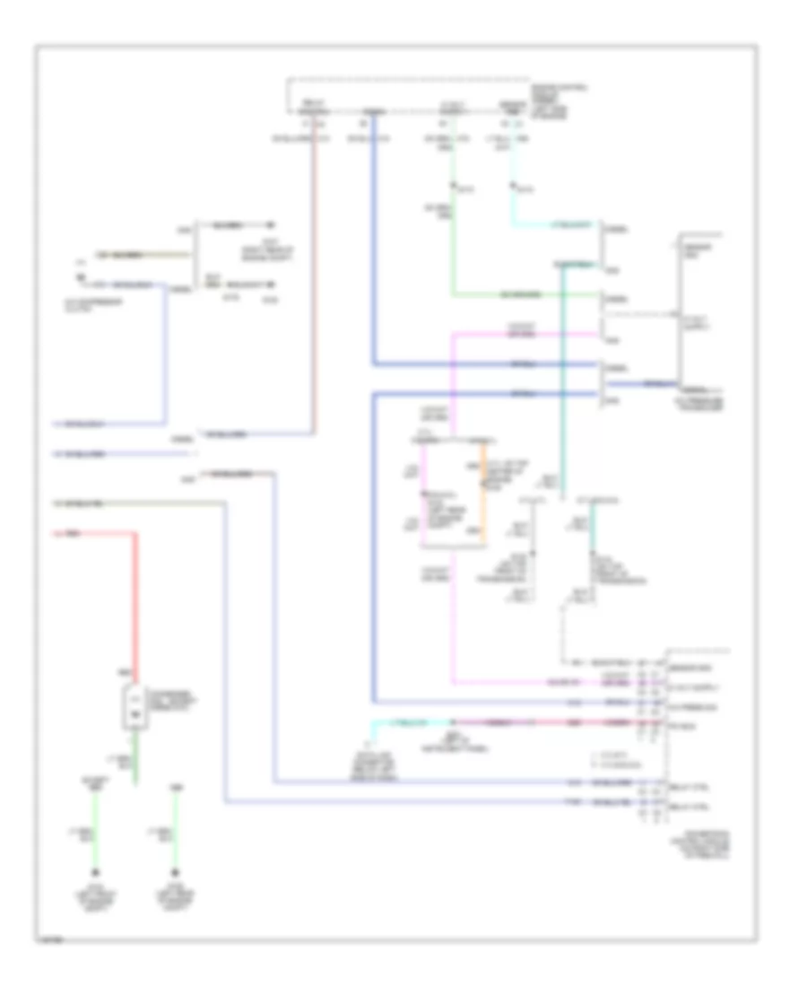
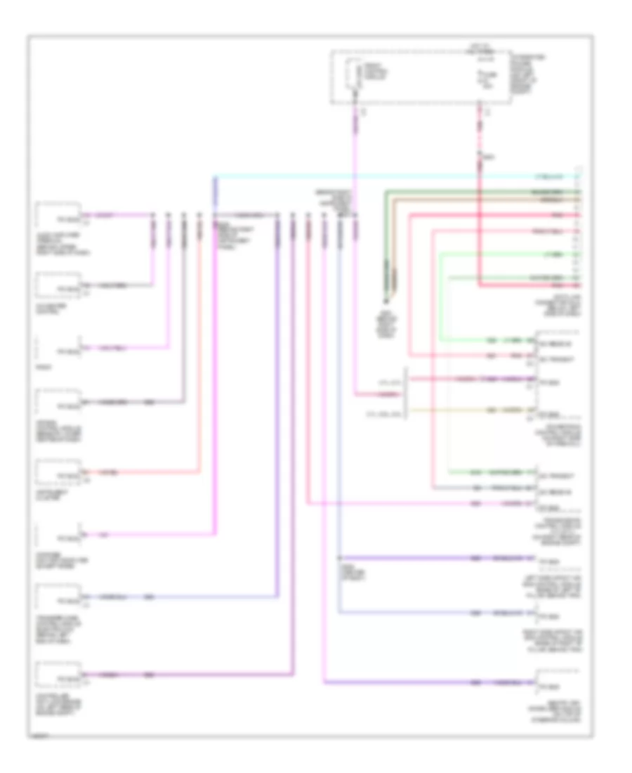
AIR CONDITIONING
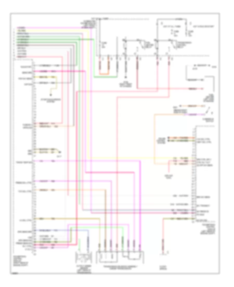
Air Conditioning Wiring Diagram (1 of 2) for Dodge Cab & Chassis R2003 3500
 https://portal-diagnostov.com/license.html
Automotive Electricians Portal FZCO
Automotive Electricians Portal FZCO
https://portal-diagnostov.com/license.html
https://portal-diagnostov.com/license.html
Automotive Electricians Portal FZCO
Automotive Electricians Portal FZCO
List of elements for Air Conditioning Wiring Diagram (1 of 2) for Dodge Cab & Chassis R2003 3500:
- (behind
- (behind center of dash)
- (below left side of dash)
- (diesel)
- (not used)
- (right side of hvac assembly) s224
- (right side of hvac assembly) s226
- (w/adjustable
- 87a
- A/c compressor clutch relay
- A/c heater control
- A/c indicator
- A/c select
- Acc
- Blend door driver
- Blower motor (beneath lower right side of dash, on hvac assembly)
- Blower motor resistor block (beneath lower right side of dash, on hvac assembly)
- Center of dash)
- Common door driver
- Condenser fan relay
- Connector
- Data link
- Driver blend door actuator (w/dual zone a/c) blend door actuator (w/o dual zone a/c) (behind right side of dash, on hvac assembly)
- Evaporator temperature sensor (behind right side of dash, inside hvac assembly)
- Fuse 10a
- Fuse 30a
- G202 (behind center of dash)
- G203
- Heated mirror
- Heated mirror relay
- Heater mirror indicator
- High
- Hot at all times
- Hot in run
- Hot in run or start
- Hvac micro controller
- Ignition switch
- Instrument cluster
- Integrated power module (on left front of engine compartment)
- Lock
- Low
- Mode door actuator 1 (behind right side of dash, on hvac assembly)
- Mode door actuator 2 (behind right side of dash, on hvac assembly)
- Off
- Panel lamps driver
- Pass blend door driver
- Passenger blend door actuator (behind right side of dash, on hvac assembly)
- Pedal)
- Ptc 1 7.5a
- Recirc
- Recirculation door actuator (behind right side of dash, on hvac assembly)
- Recirculation door driver
- Recirculation indicator
- Red
- Run
- S140 s225
- S191
- S230
- Sensor ground
- Sensor signal
- Start
- Tan
- W/dual zone a/c
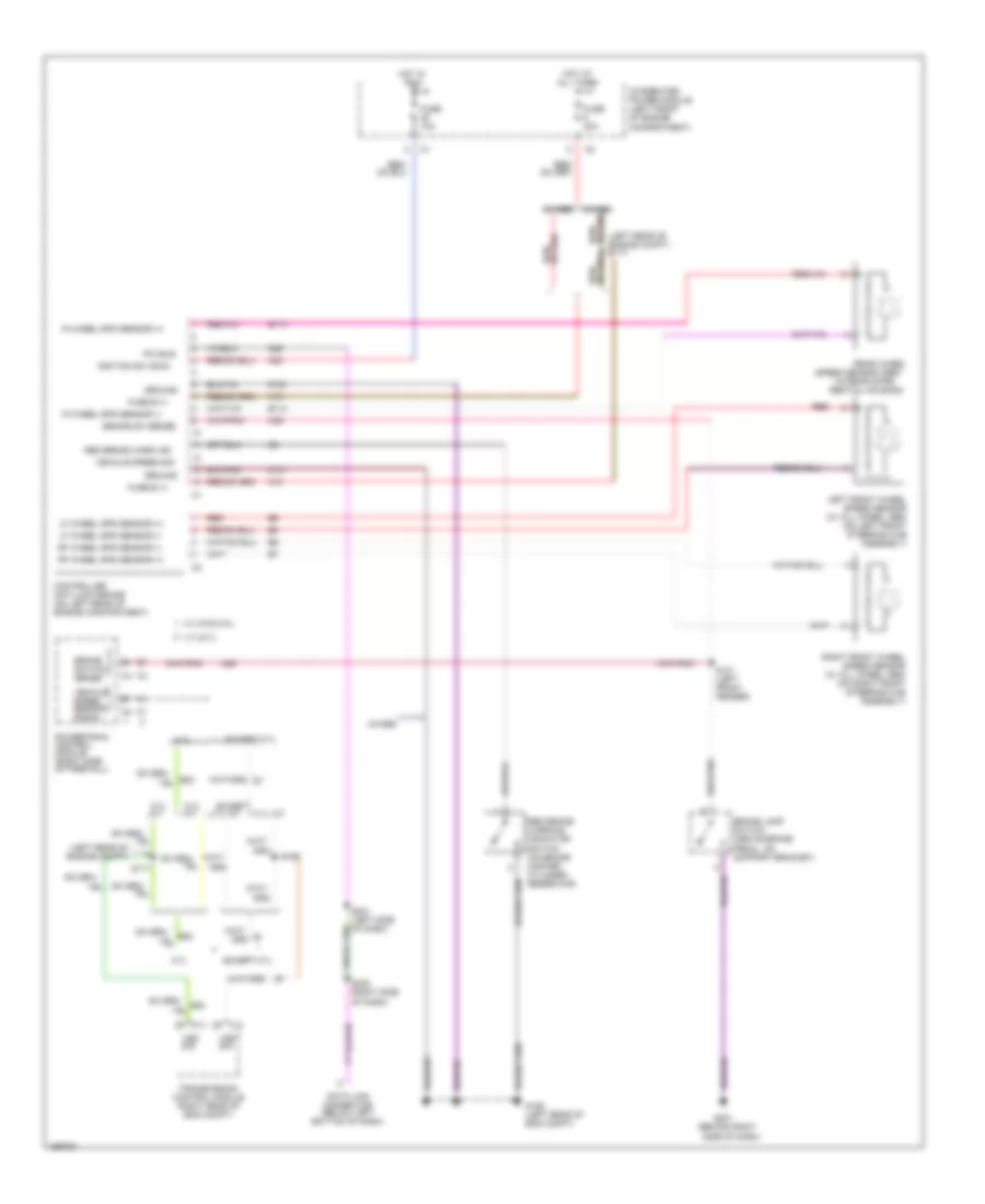
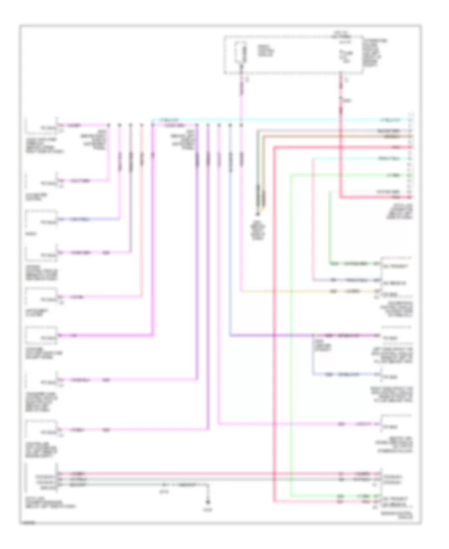
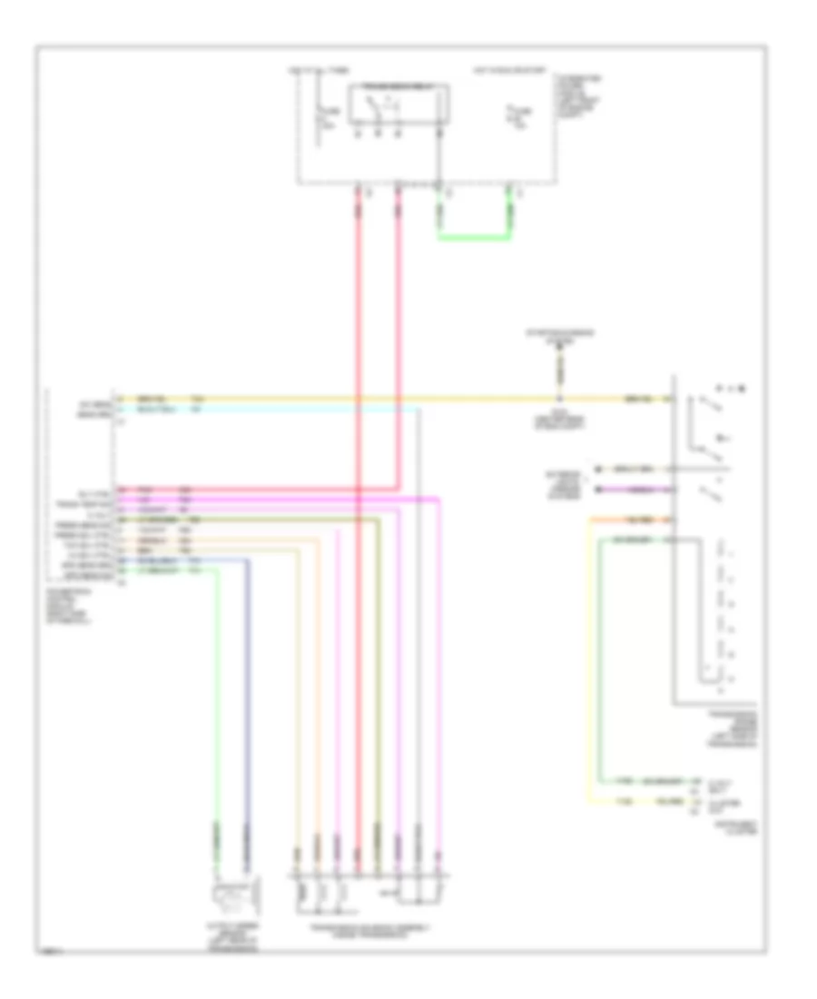
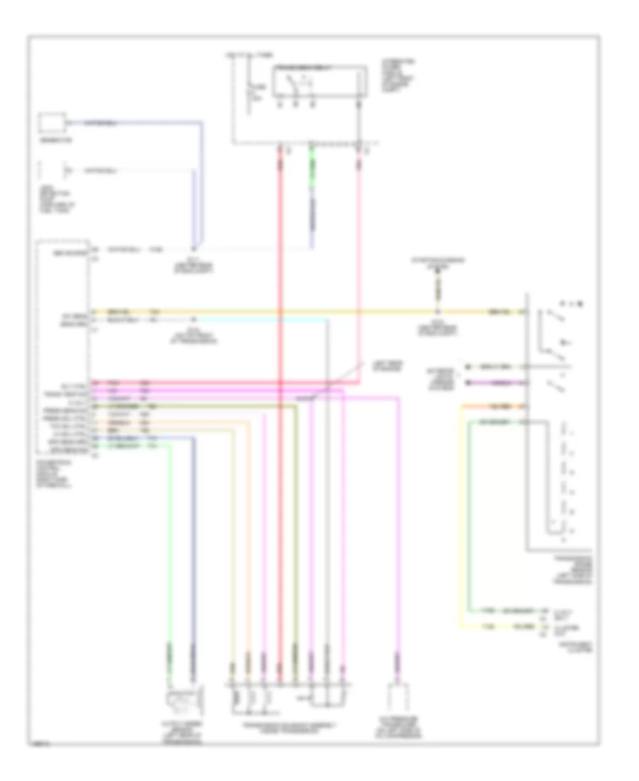
Air Conditioning Wiring Diagram (2 of 2) for Dodge Cab & Chassis R2003 3500
List of elements for Air Conditioning Wiring Diagram (2 of 2) for Dodge Cab & Chassis R2003 3500:
- (5.9l/8.0l)
- (except
- (right rear of engine compt)
- 3.7l/ 5.9l/8.0l
- 3.7l/4.7l
- 3.7l/5.9l/8.0l
- 4.7l/5.7l
- 5.7l/5.9l/8.0l
- A/c compressor clutch
- A/c press sig
- A/c pressure transducer
- Abs
- C13
- C18
- Center of engine)
- Condenser fan diesel/8.0l)
- Control
- D25
- Data link connector (below left
- Diesel
- Engine control module (diesel) (left side of engine)
- Except abs
- G104 (left front of engine compt)
- G106 (left rear of engine compt)
- G107
- G120
- Gas
- K6 (or k7)
- Pci bus
- Powertrain control module (on right side of firewall)
- Red
- Relay
- Relay ctrl
- S130 (on top front of transmission)
- S133 (left rear of engine compt)
- S144 (on top front of transmission)
- S150
- S172
- S173
- S176
- S231 (left of instrument panel)
- Sensor gnd
- Side of dash)
- Signal
- Y145
ANTI-LOCK BRAKES
Anti-lock Brakes Wiring Diagram for Dodge Cab & Chassis R2003 3500
List of elements for Anti-lock Brakes Wiring Diagram for Dodge Cab & Chassis R2003 3500:
- (behind right
- (in rear diffe-
- (left rear of engine compt) s114
- 3.7l
- 3.7l a/t
- 3.7l/5.9l/8.0l
- 4.7l/5.7l
- 4wabs
- 5.7l
- 5.7l a/t
- 5.7l m/t
- A10
- A20
- All times
- B113
- B114
- B22
- Brake lamp switch (above brake pedal, on support bracket)
- Brake sw sense
- Brake switch sense
- Controller anti-lock brake (on left rear of engine compartment)
- D25
- Data link connector (below left bottom of dash)
- Except
- Except 5.7l
- Fuse 10a
- Fuse 40a
- Fuse b (+)
- G106 (left rear of eng compt)
- G201
- Ground
- Hot at
- Hot in
- Ignition sw (run)
- Integrated power module (left front of engine compartment)
- K29
- Left front wheel speed sensor (w/ all wheel abs) (on left front steering hub assembly)
- Lf wheel spd sensor (+)
- Lf wheel spd sensor (-)
- Pci bus
- Powertrain control module (right side of firewall)
- R wheel spd sensor (+)
- R wheel spd sensor (-)
- Rear wheel
- Red
- Red brake warn ind
- Red brake warning indicator switch (on brake master cylinder reservoir)
- Red/
- Rential housing)
- Rf wheel spd sensor (+)
- Rf wheel spd sensor (-)
- Right front wheel speed sensor (w/ all wheel abs) (on right front steering hub assembly)
- Run
- Rwabs
- S117
- S121 (left front fender)
- S152
- S230 (right side of dash)
- S231 (left side of dash)
- Side of dash)
- Speed sensor (abs)
- Transmission control module (right rear of eng compt)
- Vehicle speed sensor signal
- Vehicle speed sig
- Vss sig
- Z101
- Z102
ANTI-THEFT
Anti-theft Wiring Diagram for Dodge Cab & Chassis R2003 3500
List of elements for Anti-theft Wiring Diagram for Dodge Cab & Chassis R2003 3500:
- 87a
- A14
- D cyl lck sw
- D dr ajar
- D25
- Data link connector (below left side of dash)
- Drive door lock motor/ajar switch
- Driver cylinder lock switch
- Front control module
- Fuse 20a
- Fuse 50a
- Fused b(+)
- Fused ign sw
- G201 (behind right side of dash)
- G301 (on left front of body)
- Ground
- Headlights system
- Horn relay
- Horn rly
- Horns system
- Hot at all times
- Hot in run or start
- Instrument cluster
- Integrated power module (on left front of engine compt)
- L hi beam
- L rr dr ajar
- Left rear door lock motor/ajar switch (quad cab)
- P cyl lck sw
- P dr ajar
- Park lamp relay
- Passenger cylinder lock switch
- Passenger door lock motor/ajar switch
- Pci bus
- Prk lmp rly
- Ptc 7.5a
- R hi beam
- R rr dr ajar
- Red
- Right rear door lock motor/ajar switch (quad cab)
- S110
- S136
- S213
- S230
- S231
- S311
- Sentry key immobilizer module (on top of steering column)
- Tan
- Tan/red
- Y135
- Z110
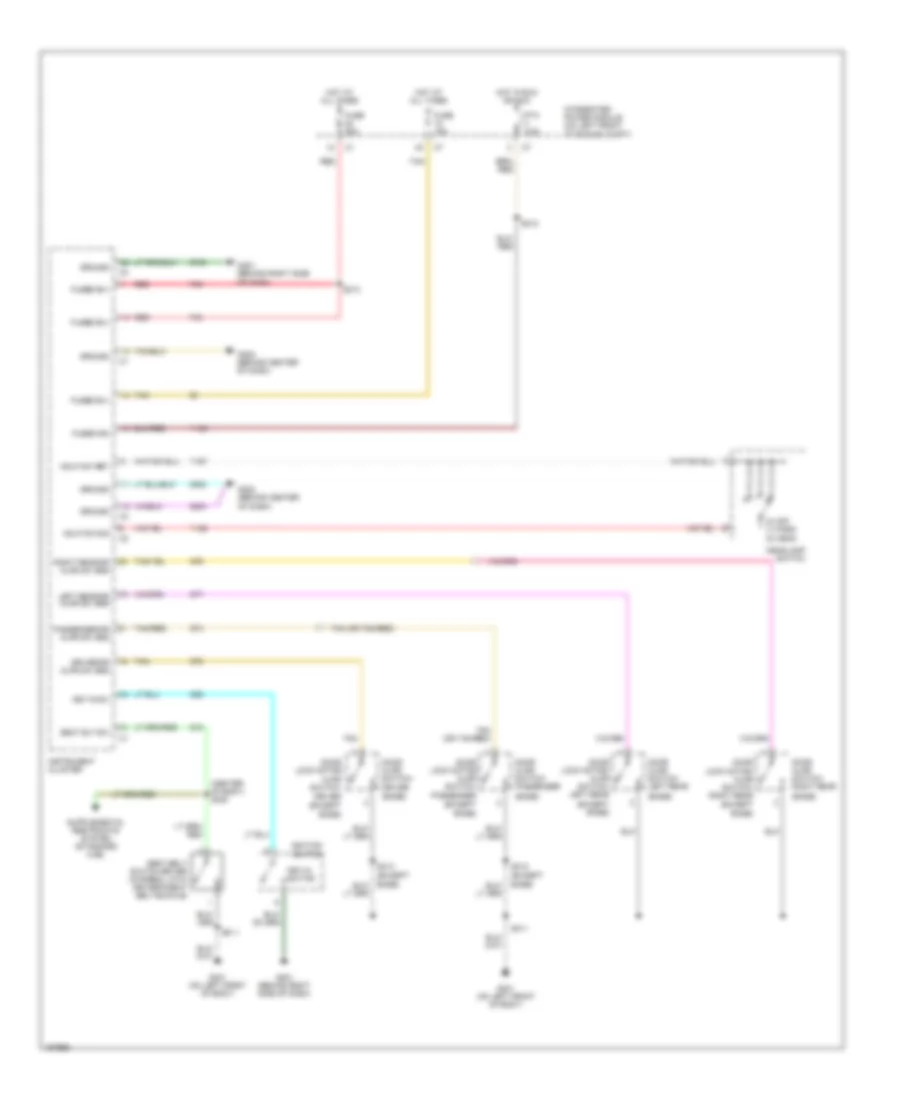
BODY CONTROL MODULES
Body Control Modules Wiring Diagram for Dodge Cab & Chassis R2003 3500
List of elements for Body Control Modules Wiring Diagram for Dodge Cab & Chassis R2003 3500:
- (left rear of engine compt) (3.7l, 5.9l, 8.0l) s119
- 8.0l/diesel
- Adj pedal relay ctrl
- Ambient temp sens signal
- Ambient temperature sensor (3.7l,5.9l,8.0l) (on left underside of hood)
- B(+)
- Backup lamp feed
- Computer data lines system
- Except 8.0l/diesel
- Exterior lights system
- Exterior lights system mirrors system, transmissions system
- Fog lamp relay ctrl
- Front control module
- Fuse 10a
- Fuse 30a
- Fused b(+)
- Fused ign (run-st)
- G103 (left front of engine compartment)
- G106 (left rear of engine compartment)
- G29
- G31
- Ground
- Headlights system
- Horn relay ctrl
- Horns system
- Hot at all times
- Hot in run & start
- Integrated power module (on left front of fender)
- Left high beam out
- Left low beam out
- Left stop lamp driver
- Left turn relay ctrl
- Lf turn lamp driver
- Low washer fluid sense
- Lr turn lamp driver
- Park lamp relay ctrl
- Pci bus
- Ptc 7.5a
- Rf turn lamp driver
- Right high beam out
- Right low beam out
- Right stop lamp driver
- Right turn relay ctrl
- Rr turn lamp driver
- Seats system
- Sensor ground
- Washer fluid level switch (on washer fluid reservoir)
- Washer pump motor ctrl
- Wiper high/low relay ctrl
- Wiper on/off relay ctrl
- Wiper park sw sense
- Wiper/washer system
- Y137
- Z12
- Z21
COMPUTER DATA LINES
5.9L
5.9L, Computer Data Lines Wiring Diagram for Dodge Cab & Chassis R2003 3500
List of elements for 5.9L, Computer Data Lines Wiring Diagram for Dodge Cab & Chassis R2003 3500:
- (3.7l/5.7l)
- (behind right side of instrument panel)
- (behind right side of instrument panel) s231
- (on right rear of engine compt)
- 3.7l, 5.9l, 8.0l
- 4.7l, 5.7l
- A/c-heater control
- Air bag control module (beneath lower center of dash)
- Audio amplifier (premium) (behind upper right side of dash)
- Compass/ mini-trip computer (except base)
- Controller anti-lock brake (on left rear of engine compt)
- D15
- D20
- D21
- D25
- Data link connector (dlc) (below left side of dash)
- Front control module
- Fuse 20a
- G201 (behind right side of dash)
- Hot at all times
- Instrument cluster
- Integrated power module (on left front of engine compt)
- Left side impact air bag control module (base of left "b" pillar, behind trim)
- Pci bus
- Pnk
- Powertrain control module (on right side of firewall)
- Radio
- Right side impact air bag control module (base of right "b" pillar, behind trim)
- S204
- S230
- S305 (center of body)
- Sci receive
- Sci transmit
- Sentry key immobilizer module (on top of steering column)
- Transfer case control module (electric 4x4) (behind left end of dash)
- Transmission control module
5.9L DIESEL
5.9L Diesel, Computer Data Lines Wiring Diagram for Dodge Cab & Chassis R2003 3500
List of elements for 5.9L Diesel, Computer Data Lines Wiring Diagram for Dodge Cab & Chassis R2003 3500:
- A/c-heater control
- Air bag control module (beneath lower center of dash)
- Audio amplifier (premium) (behind upper right side of dash)
- Ccd bus(+)
- Ccd bus(-)
- Compass/ mini-trip computer (except base)
- Controller antilock brake (on left rear of engine compt)
- D15
- D20
- D21
- D25
- Data link connector (below left side of dash)
- Data link connector-engine (below left side of dash)
- Engine control module
- Front control module
- Fuse 20a
- G120
- G201 (behind right side of dash)
- Ground
- Hot at all times
- Instrument cluster
- Integrated power module (on left front of engine compt)
- Left side impact air bag control module (base of left "b" pillar, behind trim)
- Pci bus
- Pnk
- Powertrain control module (on right side of firewall)
- Radio
- Right side impact air bag control module (base of right "b" pillar, behind trim)
- S176
- S204
- S230 (behind right side of instrument panel)
- S231 (behind left side of instrument panel)
- S305 (center of body)
- Sci receive
- Sci transmit
- Sentry key immobilizer module (on top of steering column)
- Transfer case control module (electric 4x4) (behind left end of dash)
8.0L
8.0L, Computer Data Lines Wiring Diagram for Dodge Cab & Chassis R2003 3500
List of elements for 8.0L, Computer Data Lines Wiring Diagram for Dodge Cab & Chassis R2003 3500:
- (3.7l/5.7l)
- (behind right side of instrument panel)
- (behind right side of instrument panel) s231
- (on right rear of engine compt)
- 3.7l, 5.9l, 8.0l
- 4.7l, 5.7l
- A/c-heater control
- Air bag control module (beneath lower center of dash)
- Audio amplifier (premium) (behind upper right side of dash)
- Compass/ mini-trip computer (except base)
- Controller anti-lock brake (on left rear of engine compt)
- D15
- D20
- D21
- D25
- Data link connector (dlc) (below left side of dash)
- Front control module
- Fuse 20a
- G201 (behind right side of dash)
- Hot at all times
- Instrument cluster
- Integrated power module (on left front of engine compt)
- Left side impact air bag control module (base of left "b" pillar, behind trim)
- Pci bus
- Pnk
- Powertrain control module (on right side of firewall)
- Radio
- Right side impact air bag control module (base of right "b" pillar, behind trim)
- S204
- S230
- S305 (center of body)
- Sci receive
- Sci transmit
- Sentry key immobilizer module (on top of steering column)
- Transfer case control module (electric 4x4) (behind left end of dash)
- Transmission control module
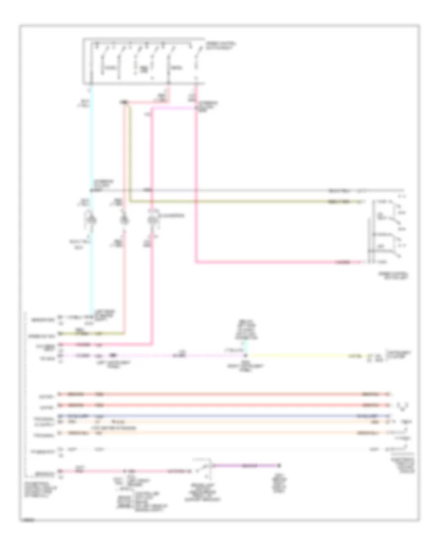
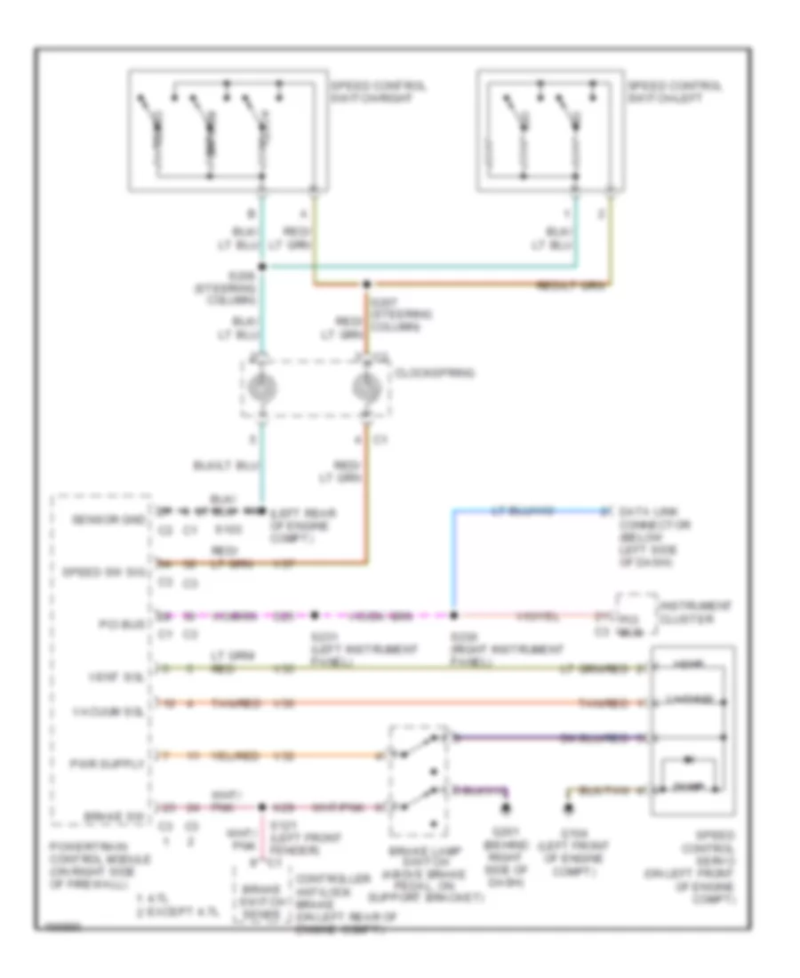
CRUISE CONTROL
5.7L
5.7L, Cruise Control Wiring Diagram for Dodge Cab & Chassis R2003 3500
List of elements for 5.7L, Cruise Control Wiring Diagram for Dodge Cab & Chassis R2003 3500:
- (below left side of dash) data link connector
- (left instrument panel)
- (left rear of engine compt)
- (steering column)
- (top center of engine)
- Accel
- Brake lamp switch (above brake pedal, on support bracket)
- Brake sw
- Brake switch sense
- Clockspring
- Controller antilock brake (on left rear of engine compt)
- D25
- Decel
- Electronic throttle control module
- F855
- F888
- G201 (behind right side of dash)
- Instrument cluster
- K101
- K22
- K29
- Motor +
- Motor -
- Mux sens input c3
- Off
- Pci bus
- Powertrain control module (on right side of firewall)
- Res- ume
- S103
- S121 (left front fender) c1
- S150
- S207
- S228
- S230 (right instrument panel)
- S231
- Sensor gnd
- Speed control switch-left
- Speed control switch-right
- Speed sw sig
- Tp sens rtn
- Tps signal
- V37
- V38
5.9L 24-VALVE DIESEL
5.9L 24-Valve Diesel, Cruise Control Wiring Diagram for Dodge Cab & Chassis R2003 3500
List of elements for 5.9L 24-Valve Diesel, Cruise Control Wiring Diagram for Dodge Cab & Chassis R2003 3500:
- (left rear of engine compt)
- 4.7l
- Accel
- Brake lamp switch (above brake pedal, on support bracket)
- Brake sw
- Brake switch sense
- Clockspring
- Controller antilock brake (on left rear of engine compt)
- D25
- Data link connector (below left side of dash)
- Decel
- Dump
- Except 4.7l
- G104 (left front of engine compt)
- G201 (behind right side of dash)
- Instrument cluster
- K29
- Off
- Pci bus
- Powertrain control module (on right side of firewall)
- Resume
- S103
- S121 (left front fender) c1
- S206 (steering column)
- S230 (right instrument panel)
- S231 (left instrument panel)
- Sensor gnd
- Speed control servo (on left front of engine compt)
- Speed control switch-left
- Speed control switch-right
- Speed sw sig
- Tan/red
- V32
- V35
- V36
- V37
- Vacuum
- Vacuum sol
- Vent
- Vent sol
8.0L
8.0L, Cruise Control Wiring Diagram for Dodge Cab & Chassis R2003 3500
List of elements for 8.0L, Cruise Control Wiring Diagram for Dodge Cab & Chassis R2003 3500:
- (left rear of engine compt)
- 4.7l
- Accel
- Brake lamp switch (above brake pedal, on support bracket)
- Brake sw
- Brake switch sense
- Clockspring
- Controller antilock brake (on left rear of engine compt)
- D25
- Data link connector (below left side of dash)
- Decel
- Dump
- Except 4.7l
- G104 (left front of engine compt)
- G201 (behind right side of dash)
- Instrument cluster
- K29
- Off
- Pci bus
- Powertrain control module (on right side of firewall)
- Resume
- S103
- S121 (left front fender) c1
- S206 (steering column)
- S230 (right instrument panel)
- S231 (left instrument panel)
- Sensor gnd
- Speed control servo (on left front of engine compt)
- Speed control switch-left
- Speed control switch-right
- Speed sw sig
- Tan/red
- V32
- V35
- V36
- V37
- Vacuum
- Vacuum sol
- Vent
- Vent sol
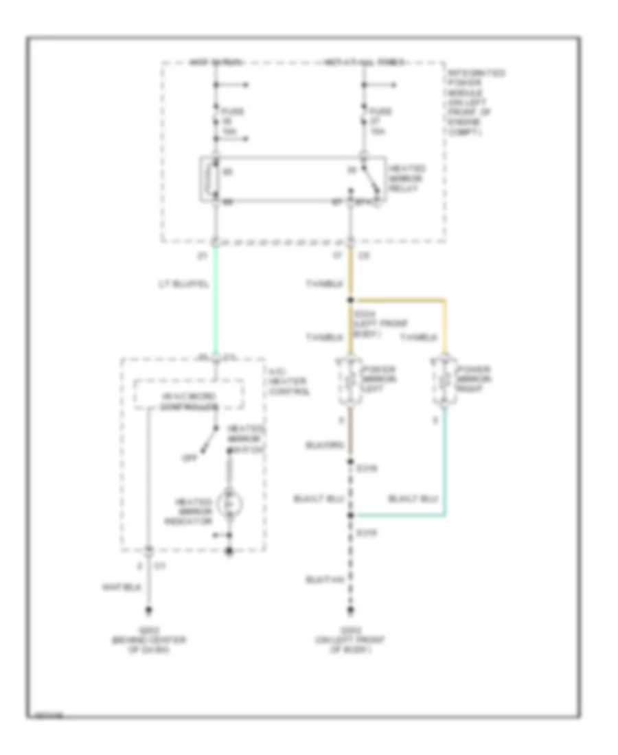
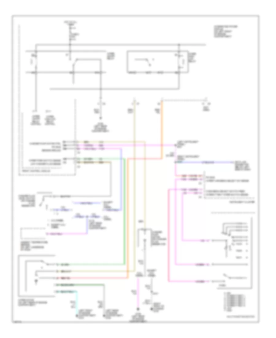
DEFOGGERS
Heated Mirrors Wiring Diagram for Dodge Cab & Chassis R2003 3500
List of elements for Heated Mirrors Wiring Diagram for Dodge Cab & Chassis R2003 3500:
- 87a
- A/c- heater control
- Fuse 10a
- Fuse 15a
- G202 (behind center of dash)
- G302 (on left front of body)
- Heated mirror indicator
- Heated mirror relay
- Heated mirror switch
- Hot at all times
- Hot in run
- Hvac micro controller
- Integrated power module (on left front of engine compt)
- Off
- Power mirror- left
- Power mirror- right
- S315
- S319
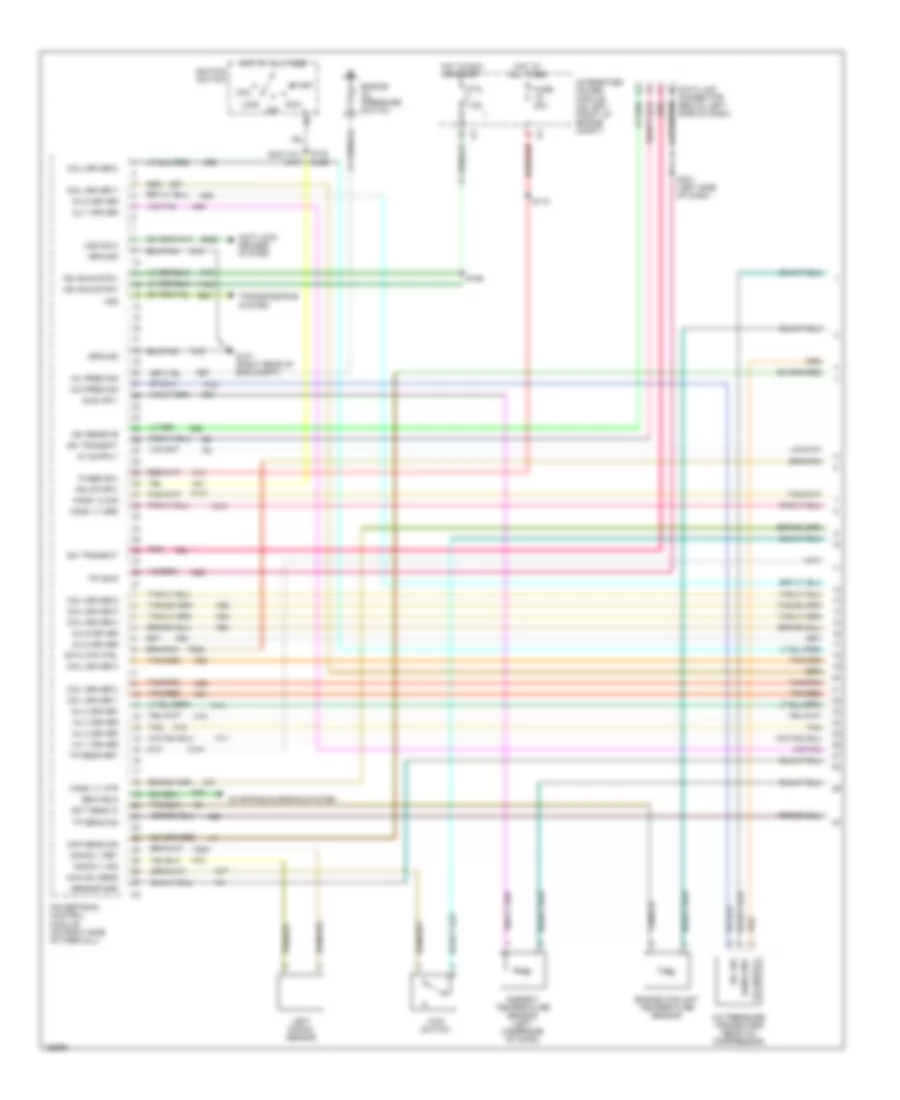
ENGINE PERFORMANCE
5.7L
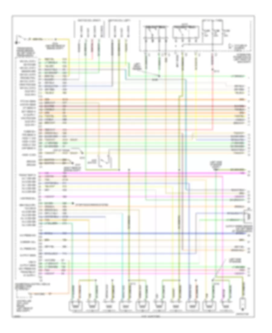
5.7L, Engine Performance Wiring Diagram (1 of 4) for Dodge Cab & Chassis R2003 3500
List of elements for 5.7L, Engine Performance Wiring Diagram (1 of 4) for Dodge Cab & Chassis R2003 3500:
- (exc a/t) (a/t)
- 4wd sw sens
- 4wd switch
- A/c pres sig
- A/c pressure transducer (near a/c compressor)
- A/c sig
- A14
- A41
- Acc
- Ambient temperature sensor (left underside of hood)
- Anti-lock brakes system
- B22
- B222
- C18
- Coil driver 1
- Coil driver 2
- Coil driver 3
- Coil driver 4
- Coil driver 5
- Coil driver 6
- Coil driver 7
- Coil driver 8
- D20
- D21
- D25
- Data link connector (below left side of dash)
- Ect sens in
- Engine coolant temperature sensor
- Engine oil pressure switch
- Etc mtr ctrl
- F18
- F888
- Fuse 20a
- Fused b(+)
- G107 (right rear of eng compt)
- G31
- G60
- Gen field
- Ground
- Ho2s 1/1 grd
- Ho2s 1/1 htr
- Ho2s 1/2 sig
- Hot at all times
- Hot in run or start
- Idle air 1
- Ign (run-strt)
- Ign (start)
- Ignition switch
- Inj 1 driver
- Inj 2 driver
- Inj 3 driver
- Inj 4 driver
- Inj 5 driver
- Inj 6 driver
- Inj 7 driver
- Inj 8 driver
- Integrated power module (on left front of engine compt)
- K101
- K11
- K12
- K13
- K14
- K141
- K20
- K22
- K26
- K28
- K38
- K41
- K58
- K73
- K77
- K91
- K92
- K93
- K94
- K95
- K97
- K98
- Knock 1 ret
- Knock 1 sig
- Left knock sensor
- Lock
- Map sens sig
- Off
- Oil pres sig
- Pci bus
- Pnk
- Powertrain control module (on right side of firewall)
- Ptc 7.5a
- Run
- S110
- S122 s126
- S186
- S231 (left side of dash)
- Sci receive
- Sci transmit
- Sens gnd
- Sensor gnd
- Start
- Starting/charging system
- Tan
- Tan/pnk
- Tan/red
- Tp sens ret
- Tp sens sig
- Transmissions system
- Vss
- Vss sig 2
- Y135
- Y205
- Y213
- Z12
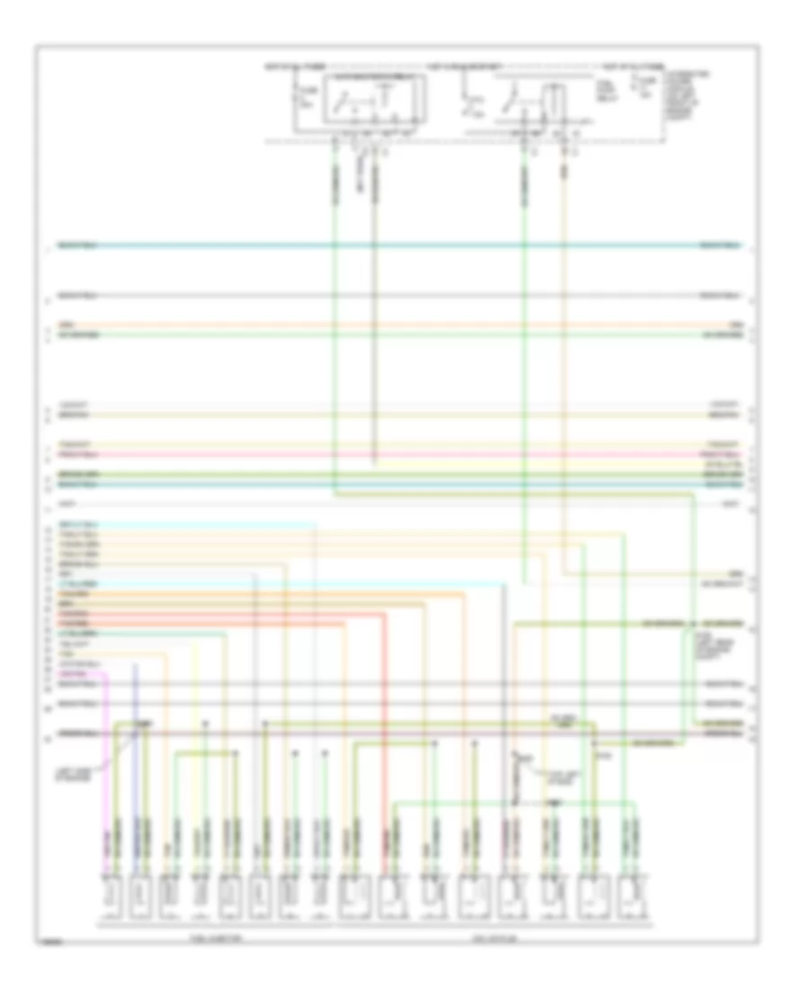
5.7L, Engine Performance Wiring Diagram (2 of 4) for Dodge Cab & Chassis R2003 3500
List of elements for 5.7L, Engine Performance Wiring Diagram (2 of 4) for Dodge Cab & Chassis R2003 3500:
- (left side of engine)
- (not used)
- (top left of eng)
- Auto shutdown relay
- Coil on plug
- Fuel injector
- Fuel pump relay
- Fuse 15a
- Fuse 30a
- Hot at all times
- Hot in run or start
- Integrated power module (on left front of engine compt)
- Ptc 7.5a
- S142
- S155 (left rear of engine compt)
- S160
- S162
- S163
- Tan
- Tan/pnk
- Tan/red
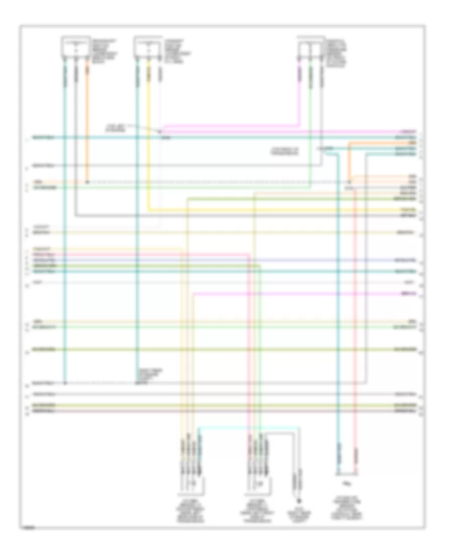
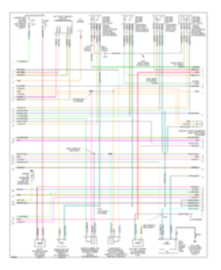
5.7L, Engine Performance Wiring Diagram (3 of 4) for Dodge Cab & Chassis R2003 3500
List of elements for 5.7L, Engine Performance Wiring Diagram (3 of 4) for Dodge Cab & Chassis R2003 3500:
- (right rear of engine compt) s132
- (top front of transmission)
- (top left of engine)
- Camshaft position sensor (lower front of right cyl head)
- Crankshaft position sensor (lower right side of eng block)
- G107 (right rear of engine compt)
- Intake air temperature sensor (on intake manifold, near throttle body)
- Manifold absolute pressure sensor (on front of intake) manifold)
- Nca
- Oxygen sensor 1/1 (upstream) (near left front side of transmission)
- Oxygen sensor 1/2 (downstream) (near left rear side of transmission)
- S130
- S150
- S154
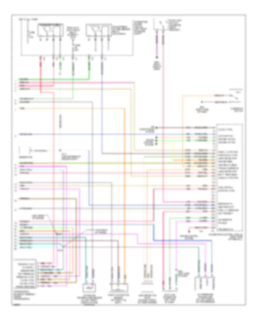
5.7L, Engine Performance Wiring Diagram (4 of 4) for Dodge Cab & Chassis R2003 3500
List of elements for 5.7L, Engine Performance Wiring Diagram (4 of 4) for Dodge Cab & Chassis R2003 3500:
- (left rear of engine compt)
- (right side of dash)
- (top front of trans)
- (unused pins not shown)
- 1/2 htr ctrl
- 5 volt
- A142
- Ac comp cltch
- Accelerator pedal position sensor
- Air conditioning system
- App 1 out
- Apps 1 ret
- Apps 1 sig
- Apps 2 ret
- Apps 2 sig
- Asd relay out
- Auto sht rly
- Batt temp sens
- Battery temperature sensor (under battery tray)
- Brake lamp switch (above brake pedal)
- Brake sw sens
- Brk sw 2 sig
- C13
- Ckp sens sig
- Clockspring
- Cmp sig
- Controller anti-lock brake (on left rear of eng compt)
- Cooling fans system
- Cruise control system
- Cruise sw sig
- Electronic throttle control module
- Etc mtr ctrl
- Evap/purge solenoid (left front of engine compt)
- F855
- Fan rly ctrl
- Fuel level sens
- Fuel pump module (inside fuel tank)
- Fuel pump rly
- G104 (abs) g103 (exc abs) (left front of engine compt)
- G107 right rear of eng compt)
- G113
- G201
- Ho2s 1/2 rtn
- Ho2s sens 1/1
- Iat sig
- K106
- K107
- K108
- K118
- K122
- K199
- K21
- K223
- K24
- K255
- K31
- K44
- K51
- K52
- K74
- K81
- K902
- K981
- K99
- Knock 2 ret
- Knock 2 sig
- Ldp sw sens
- Leak detection pump (forward of fuel tank)
- Pmp sol ctrl
- Power steering pressure switch (below power steering reservoir)
- Powertrain control module (on right side of firewall)
- Prs sw sig
- Pto sw sens
- Pto switch
- Req sens
- Right knock sensor
- Rpm sig
- S/c sw 2 sig
- S103
- S121 (left front fender)
- S144
- S28
- S308
- Sens grd
- Sense
- Sol ctrl
- Starting/ charging system
- Strtr mtr rly
- T10
- T752
- Tp 2 sig
- Tps 1 out
- Trans- missions system
- V32
- V37
- V38
- V40
- Y145
- Y206
- Y207
- Y208
- Y209
- Y210
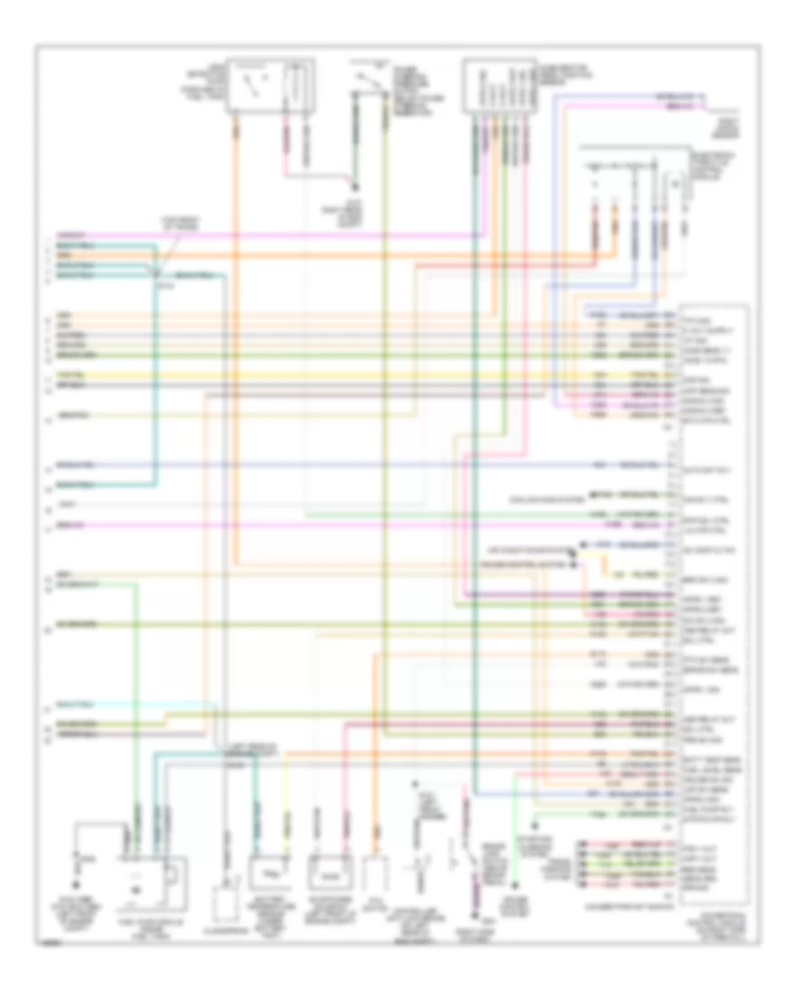
5.9L DIESEL
5.9L Diesel, Engine Performance Wiring Diagram (1 of 4) for Dodge Cab & Chassis R2003 3500
List of elements for 5.9L Diesel, Engine Performance Wiring Diagram (1 of 4) for Dodge Cab & Chassis R2003 3500:
- (on left side of engine) fuel control actuator
- (right side of engine) water in fuel sensor
- 5 volt
- A/c press sig
- A/c pressure transducer (left side of a/c compressor)
- Apps idle sw
- Apps sig
- B data link a connector (engine) (near breakout for water in fuel sensor)
- C18
- Camshaft position sensor
- Ccd bus (+)
- Ccd bus (-)
- Ckp sig
- Com inj driver
- Crankshaft position sensor
- Ect sens sig
- Engine control module (on lower left side of engine)
- Engine coolant temperature sensor
- Fuel injector
- Fuel pump sply
- G120
- G17
- G20
- G910
- Gen field ctrl
- Hall
- Hall effect
- Iat press ret
- Iat sens sig
- Ign sw sens
- K101
- K102
- K104
- K118
- K12
- K13
- K14
- K167
- K20
- K21
- K232
- K31
- K38
- K49
- K53
- K55
- K56
- K58
- K62
- K65
- K72
- K900
- K91
- K92
- Letf pmp
- Lift pump motor (near breakout for wif sensor)
- Maf sens sig
- Map sens sig
- No 1 driver
- No 2 driver
- No 3 driver
- No 4 driver
- No 5 driver
- No 6 driver
- No. 1
- No. 2
- No. 3
- No. 4
- No. 5
- No. 6
- Pmp rly ctrl
- Press sens sig
- Press sig ret
- S157
- S158
- S159
- S160
- S170
- S171
- S172
- S173
- S174
- S175
- S176
- Sens grd
- Sensor ground
- Sig
- Starting/charging system
- Tan
- Tan/pnk
- Tan/red
- Throttle position switch
- Tps ret
- Y501
- Y502
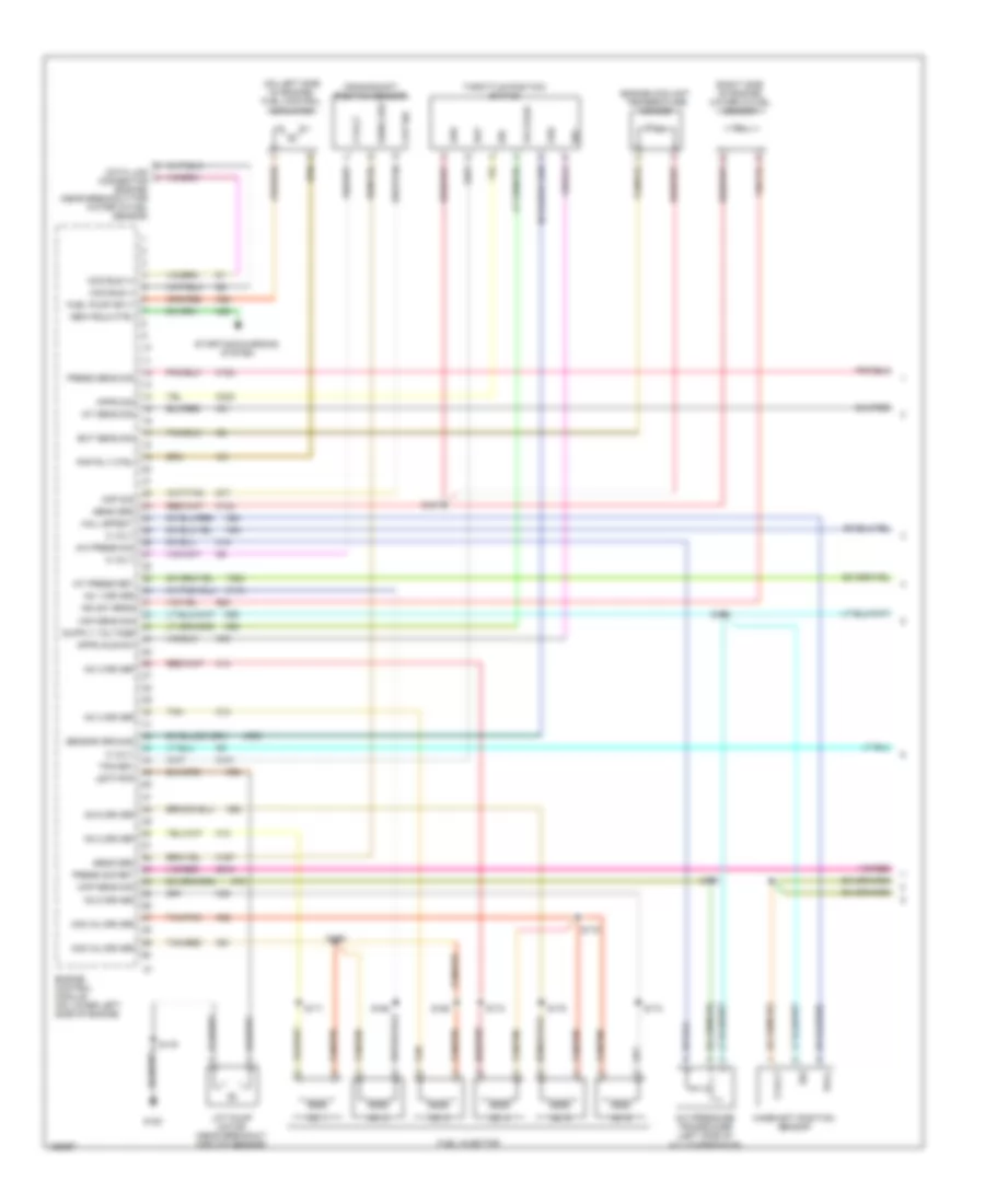
5.9L Diesel, Engine Performance Wiring Diagram (2 of 4) for Dodge Cab & Chassis R2003 3500
List of elements for 5.9L Diesel, Engine Performance Wiring Diagram (2 of 4) for Dodge Cab & Chassis R2003 3500:
- 5 volt
- Battery temperature sensor (under battery tray)
- Brake lamp switch (above brake pedal)
- Fuel rail pressure sensor
- G105 (right front of chassis)
- G201 (right side of dash)
- Inlet air temperature/ pressure sensor
- Intake air temperature/ manifold pressure sensor
- S101
- Sig
- Sig ret
- Speed control servo (left front of eng compt)
- Vacuum pump
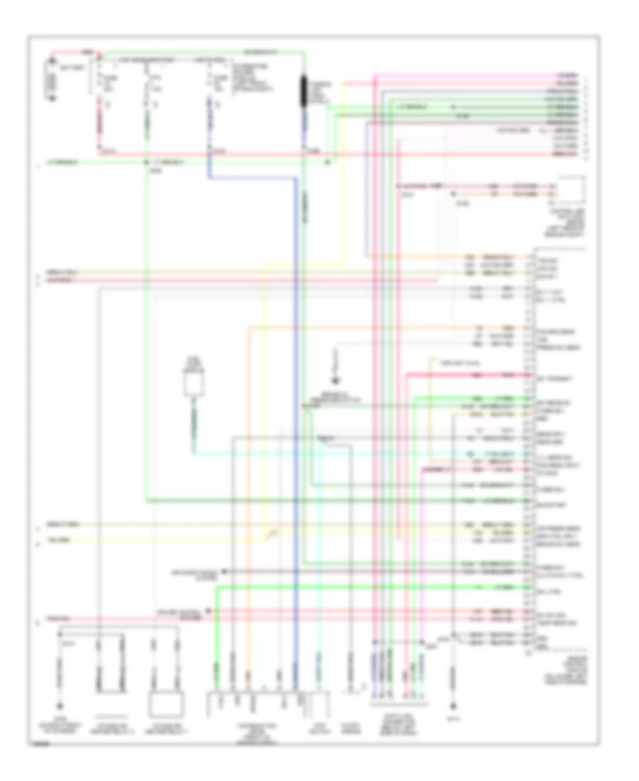
5.9L Diesel, Engine Performance Wiring Diagram (3 of 4) for Dodge Cab & Chassis R2003 3500
List of elements for 5.9L Diesel, Engine Performance Wiring Diagram (3 of 4) for Dodge Cab & Chassis R2003 3500:
- 4wd switch
- A140
- Air conditioning system
- Air press sens
- Battery
- Brake sw sens
- C13
- Ckp sig
- Clock- spring
- Clutch rly ctrl
- Controller anti-lock brake (left rear of engine compt)
- Cruise control system
- Ctrl
- D20
- D21
- D25
- Data link connector (below left side of dash)
- Engine control module (on lower left side of engine)
- Engine oil pressure switch
- Fan spd sens
- Fuel pump module
- Fuse 10a
- Fuse 20a
- Fused b(+)
- G105 (on right front of chassis)
- G114
- G60
- Grd
- Hot in run
- Hot in run or start
- Info not avail
- Intake air heater relay 1
- Intake air heater relay 2
- Integrated power module (left front of eng compt)
- K118
- K152
- K154
- K22
- K24
- K29
- K68
- K69
- K77
- Lvl sens sig
- Nca
- Pci bus
- Pnk
- Pos sens input
- Press sw sens
- Ptc 7.5a
- Red
- Rly 1 ctrl
- Rly 1 out
- Run
- Run/start
- S/c sw sig
- S101
- S110
- S121
- S127
- S129
- S136
- S140
- S144
- S156
- S164
- S165
- S166
- S231
- Sci receive
- Sci transmit
- Sens grd
- Sens sply
- Sig no 1
- Sol ctrl
- Spd ctrl sply
- Speed
- Sply
- Temp sens sig
- Tps sig
- V32
- V37
- Vistronic fan drive (front of engine compt)
- Vss
- Y135
- Z816
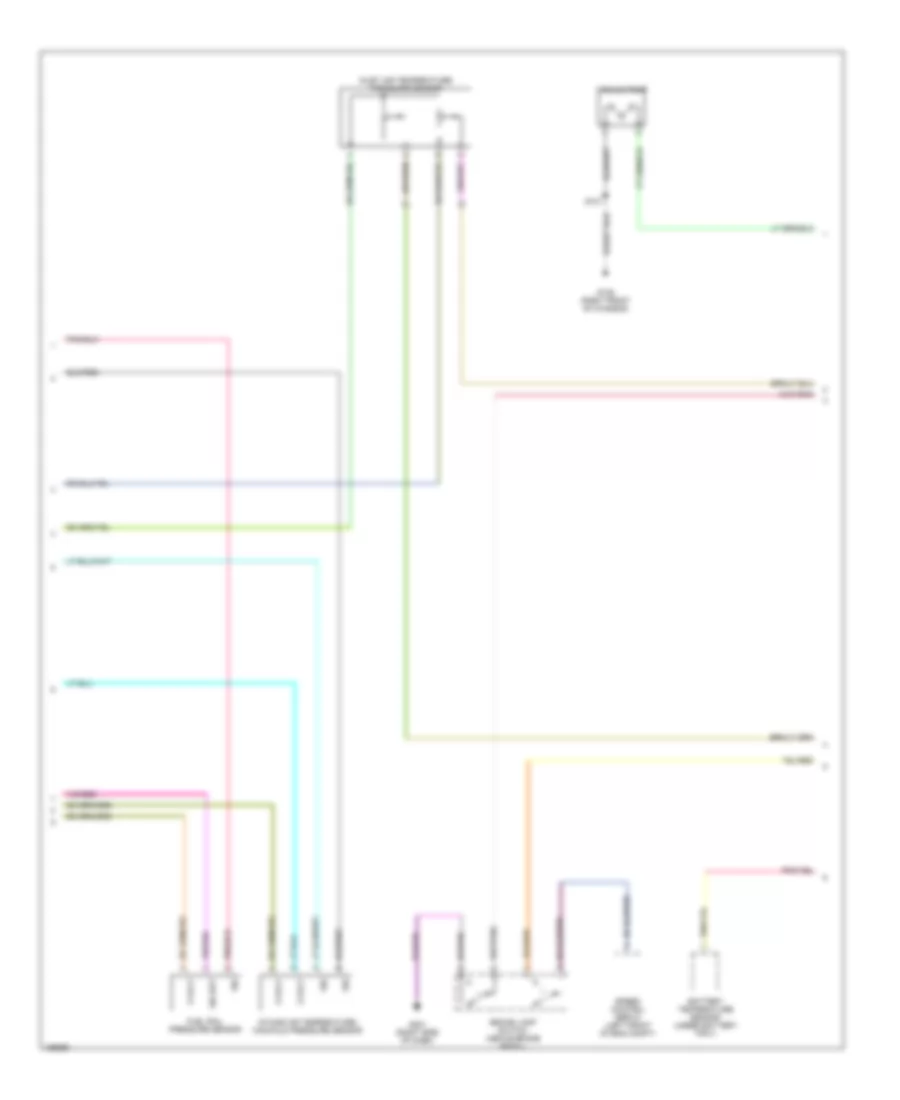
5.9L Diesel, Engine Performance Wiring Diagram (4 of 4) for Dodge Cab & Chassis R2003 3500
List of elements for 5.9L Diesel, Engine Performance Wiring Diagram (4 of 4) for Dodge Cab & Chassis R2003 3500:
- (behind right side of dash)
- 3-4 sol ctrl
- 5 volt
- A14
- Apps sig
- Brk sw sens
- Ckp sig
- Clock- spring
- Cruise control system
- Ctrl rly out
- D15
- D25
- Fuel heater (left side of engine)
- Fuel heater relay
- Fuse 10a
- Fuse 40a
- Fuse b(+)
- G106 (right front of chassis)
- G117
- G120
- G201
- Grd
- Hot at all times
- Hot in run or start
- Info not avail
- Integrated power module (left front of eng compt)
- K22
- K24
- K29
- K30
- K54
- K88
- K914
- Od off sw sens
- Output speed sensor (left rear of transmission)
- Overdrive switch
- Pci bus
- Pnk
- Pnp sw sens
- Powertrain control module (left rear of engine compt)
- Powertrain control module (right rear of engine compt)
- Press sens sig
- Press sol ctrl
- Red
- Red/tan
- Rly ctrl
- Run/start
- S/c sw sig
- S176
- Sci receive
- Sci transmit
- Sens grd
- Spd ctrl sply
- Spd sens grd
- Spd sens sig
- Starting/charging system
- T13
- T14
- T16
- T24
- T25
- T54
- T60
- Tan/red
- Tcc sol ctrl
- Trans temp sig
- Transmission control relay
- Transmission solenoid assembly (inside transmission)
- V32
- V35
- V36
- V37
- Vac sol ctrl
- Vent sol ctrl
- Vss
- Y135
- Z81
- Z82
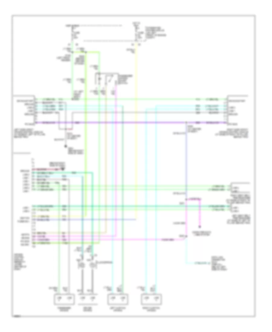
8.0L
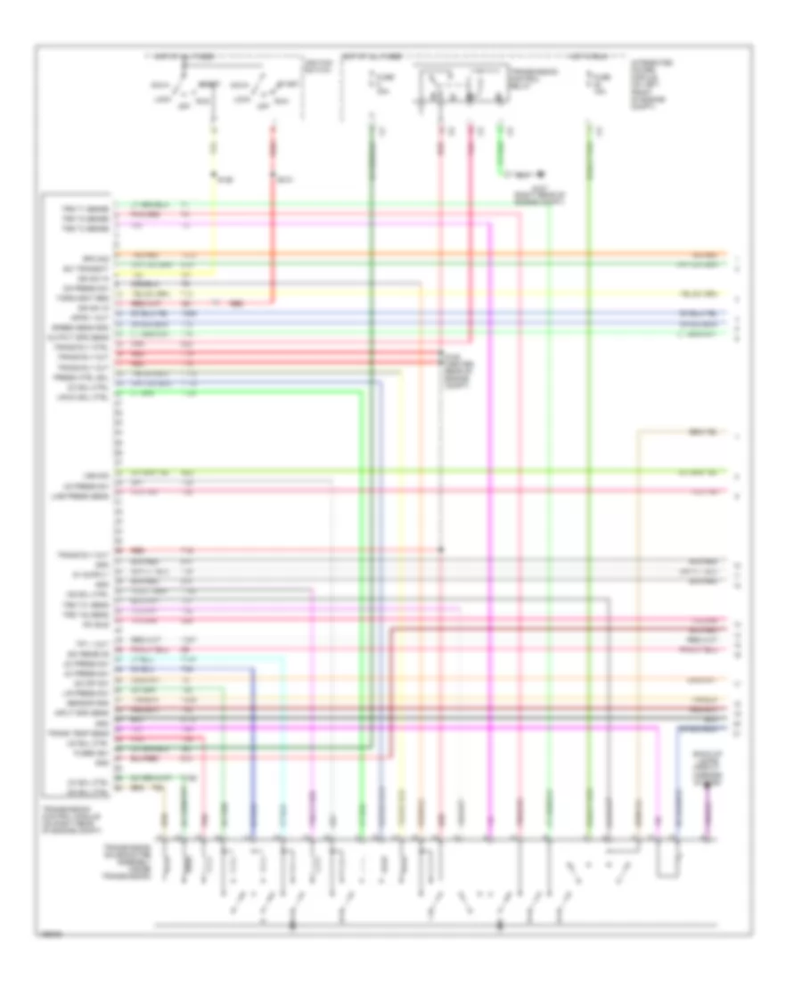
8.0L, Engine Performance Wiring Diagram (1 of 3) for Dodge Cab & Chassis R2003 3500
List of elements for 8.0L, Engine Performance Wiring Diagram (1 of 3) for Dodge Cab & Chassis R2003 3500:
- (calif)
- (left front fender)
- (left side of engine compt)
- (left side of engine)
- (not used)
- (right rear of engine compt)
- (top of trans)
- 4wd sw sens
- 4wd switch
- A/c press sig
- A14
- Auto shut down relay
- C18
- Cam pos sns
- Capacitor
- Controller anti-lock brake (left rear of eng compt)
- Crnk pos sns
- Ect sens in
- F18
- Fuel injectors
- Fuel pump relay
- Fuse 15a
- Fuse 20a
- Fuse 30a
- Fused b(+)
- G107
- G113
- G60
- Gen field drv
- Gov press sig
- Ground
- Ho2s 1/1 sig
- Ho2s 1/2 sig
- Ho2s 1/3 sig
- Ho2s 2/1 sig
- Hot at all times
- Iat sens in
- Idle air 1
- Idle air 2
- Idle air 3
- Idle air 4
- Ign coil dvr 1
- Ign coil dvr 2
- Ign coil dvr 3
- Ign coil dvr 4
- Ign coil dvr 5
- Ign power
- Ignition coil (left)
- Ignition coil (right)
- Inj 1 driver
- Inj 10 driver
- Inj 2 driver
- Inj 3 driver
- Inj 4 driver
- Inj 5 driver
- Inj 6 driver
- Inj 7 driver
- Inj 8 driver
- Inj 9 driver
- Integrated power module (left front of eng compt)
- K11
- K115
- K116
- K12
- K13
- K14
- K141
- K17
- K18
- K19
- K20
- K21
- K22
- K24
- K241
- K26
- K28
- K30
- K32
- K38
- K39
- K40
- K41
- K43
- K44
- K54
- K58
- K59
- K60
- K77
- K88
- Map sens in
- No 1 drvr
- No 2 drvr
- No 3 drvr
- No 4 drvr
- No 5 drvr
- Oil press sig
- Output sens
- Output speed sensor (on left rear of transmission)
- Overdrv sol
- Pnk
- Powertrain control module (on right side of firewall)
- Prk/neutral
- Pto sw sens
- Rly out
- S110
- S112
- S124 (center rear of engine compt)
- S136
- S142
- S143
- S181
- Sensor grd
- Starting/charging system
- T13
- T14
- T24
- T25
- T54
- T60
- Tan
- Tcc drvr
- To fuse 49 (diagram 3 of 3)
- Tps sens in
- Trans relay
- Trans temp in
- Transmission range sensor (on left side of transmission)
- Var frce sol
- Vss in
- Z81
- Z82
8.0L, Engine Performance Wiring Diagram (2 of 3) for Dodge Cab & Chassis R2003 3500
List of elements for 8.0L, Engine Performance Wiring Diagram (2 of 3) for Dodge Cab & Chassis R2003 3500:
- (calif)
- (down- stream) (right exhaust downpipe, downstream of converter)
- (left exhaust downpipe, downstream of converter)
- (left rear of eng compt)
- (left rear of engine)
- (on right lower side of cylinder block, above oil pan rail)
- (on throttle body) idle air control motor
- (right front of trans)
- (right rear of eng compt)
- (top center of engine)
- (top front of trans)
- Battery temper- ature sensor (below battery tray)
- Camshaft position sensor (right front side of engine)
- Clockspring
- Crankshaft position sensor
- Drvr 1
- Drvr 2
- Drvr 3
- Drvr 4
- Engine coolant temperature sensor (on thermostat housing)
- Engine oil pressure switch (lower left side of eng)
- Evap/ purge solenoid (left front of engine compt)
- Fuel pump module (inside fuel tank)
- Fuse 10a
- G104 (abs) g103 (exc abs) (left front of engine compt)
- G107 (right rear of eng compt)
- Heated oxygen sensor 1/1 (upstream) (near left front side of trans)
- Heated oxygen sensor 1/2 (down- stream)
- Heated oxygen sensor 2/1 (upstream) (near right front side of transmission)
- Heated oxygen sensor 2/2
- Hot in run or start
- Integrated power module (left front of engine compt)
- Manifold absolute pressure sensor (on right upper side of intake manifold)
- Nca
- Pnk
- Ptc 7.5a
- Pto switch
- Red
- S103
- S130
- S132
- S138
- S139
- S150
- S182 (top of trans)
- S183
- S184 (top of trans)
- S308
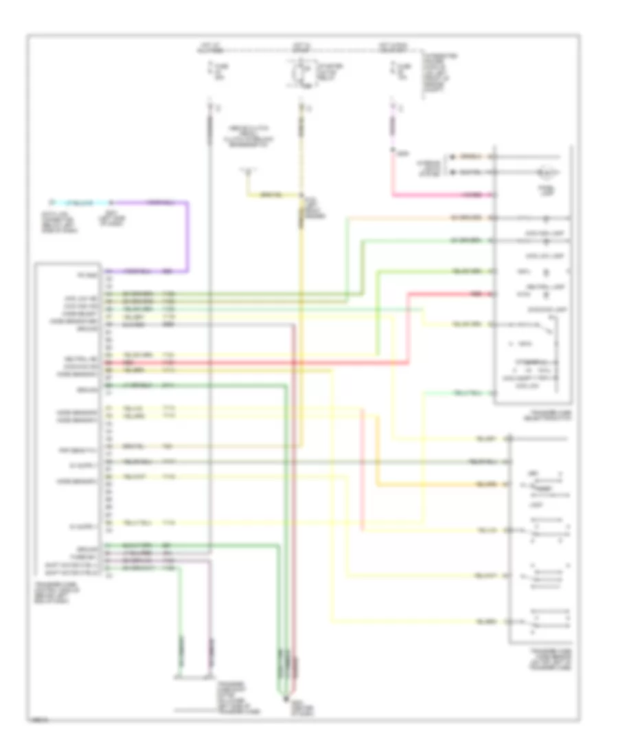
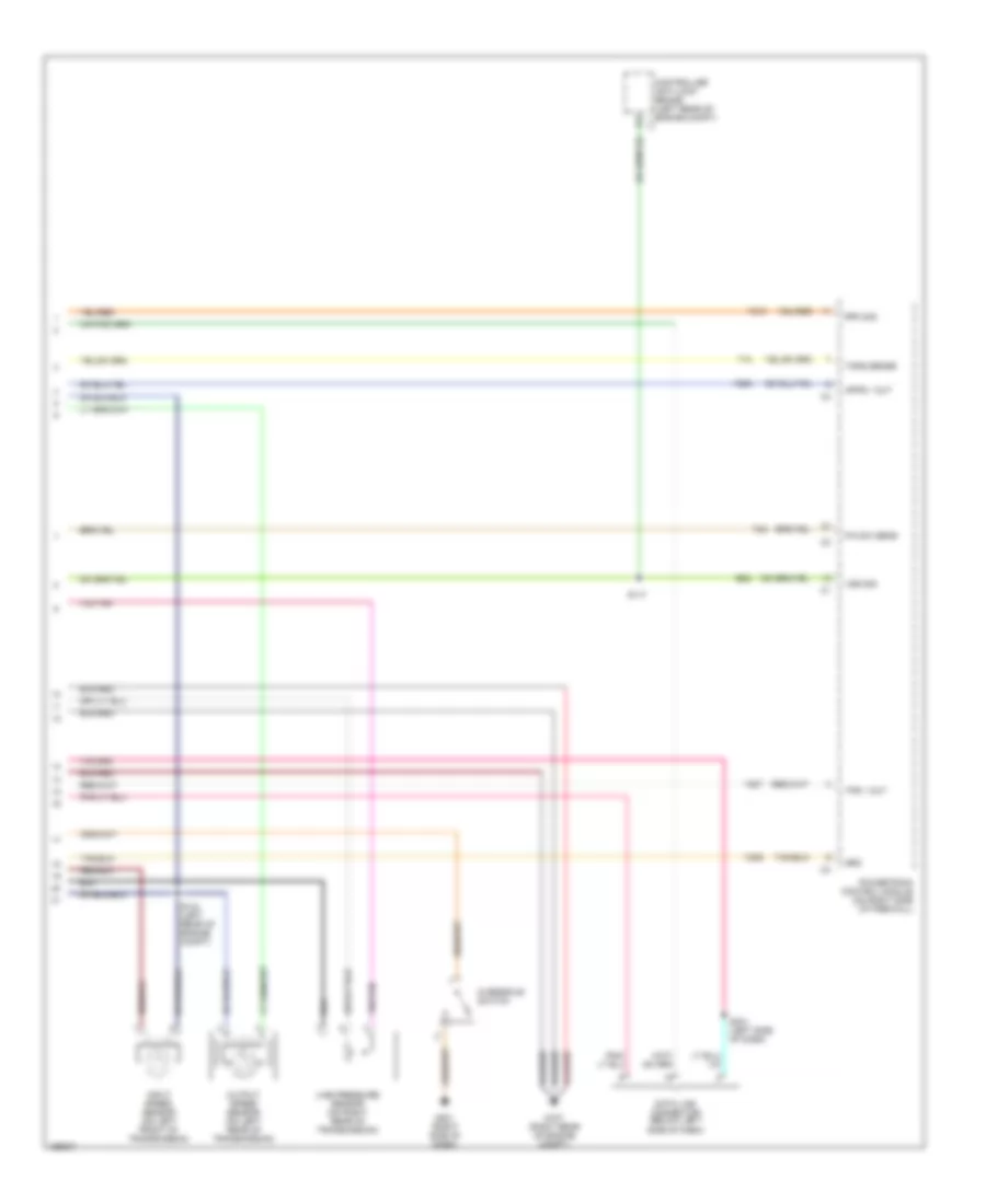
8.0L, Engine Performance Wiring Diagram (3 of 3) for Dodge Cab & Chassis R2003 3500
List of elements for 8.0L, Engine Performance Wiring Diagram (3 of 3) for Dodge Cab & Chassis R2003 3500:
- (left rear of engine)
- (left side of dash)
- (top front of trans)
- 3-4 sol ctrl
- 5 volt
- A/c pressure transducer (on left side of a/c compressor)
- A/c rly ctrl
- A142
- Air conditioning system
- Asd relay sens
- Auto sht rly
- Batt temp sens
- Brake sw in
- C13
- Cruise control system
- Cruise feed
- Cruise sw in
- Cruise vac sol
- Cruise vnt sol
- D20
- D21
- D25
- Data link connector (left side of dash)
- Downstream oxygen sensor relay (california)
- Evap sol ctrl
- From auto shut down relay (diagram 1 of 3)
- Fuel lvl sens sig
- Fuel pmp rly
- Fuse 20a
- Fuse 40a
- G201 (right side of dash)
- Gen field out
- Generator
- Gov press sig
- Ho2s 1/1 htr ctrl
- Ho2s 2/1 htr ctrl
- Ho2s dn rly ctrl
- Hot at all times
- Intake air temperature sensor (in left front side of intake manifold)
- Integrated power module (left front of engine compt)
- K106
- K107
- K118
- K125
- K127
- K199
- K299
- K31
- K51
- K52
- K54
- K88
- Leak detec pmp
- Leak detection pump (on right front of inner fender)
- Overdrive switch
- Pci bus
- Pnk
- Powertrain control module (right side of firewall)
- Press sig
- Press sol ctrl
- Red
- S111 (center rear of engine compt)
- S133
- S144
- S231
- Sci receive
- Sci transmit
- Sens grd
- Sensor grd
- Stop lamp switch (on brake pedal bracket)
- T16
- T25
- T54
- T60
- Tan/red
- Tcc sol ctrl
- Throttle position sensor (on throttle body)
- Trans overdrive
- Trans rly out
- Trans temp sns
- Transmission relay
- Transmission solenoid assembly (inside transmission)
- V32
- V35
- V36
- V37
- V40
EXTERIOR LIGHTS
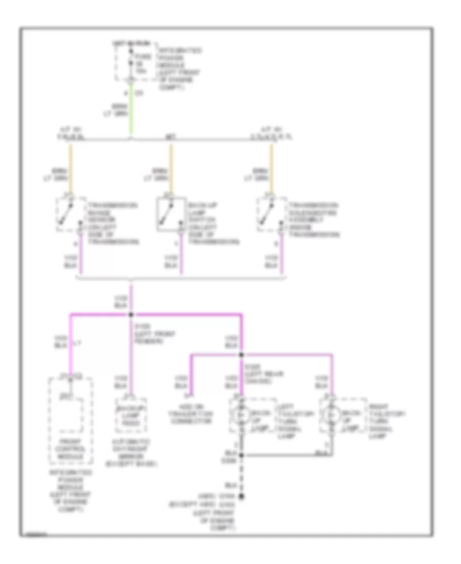
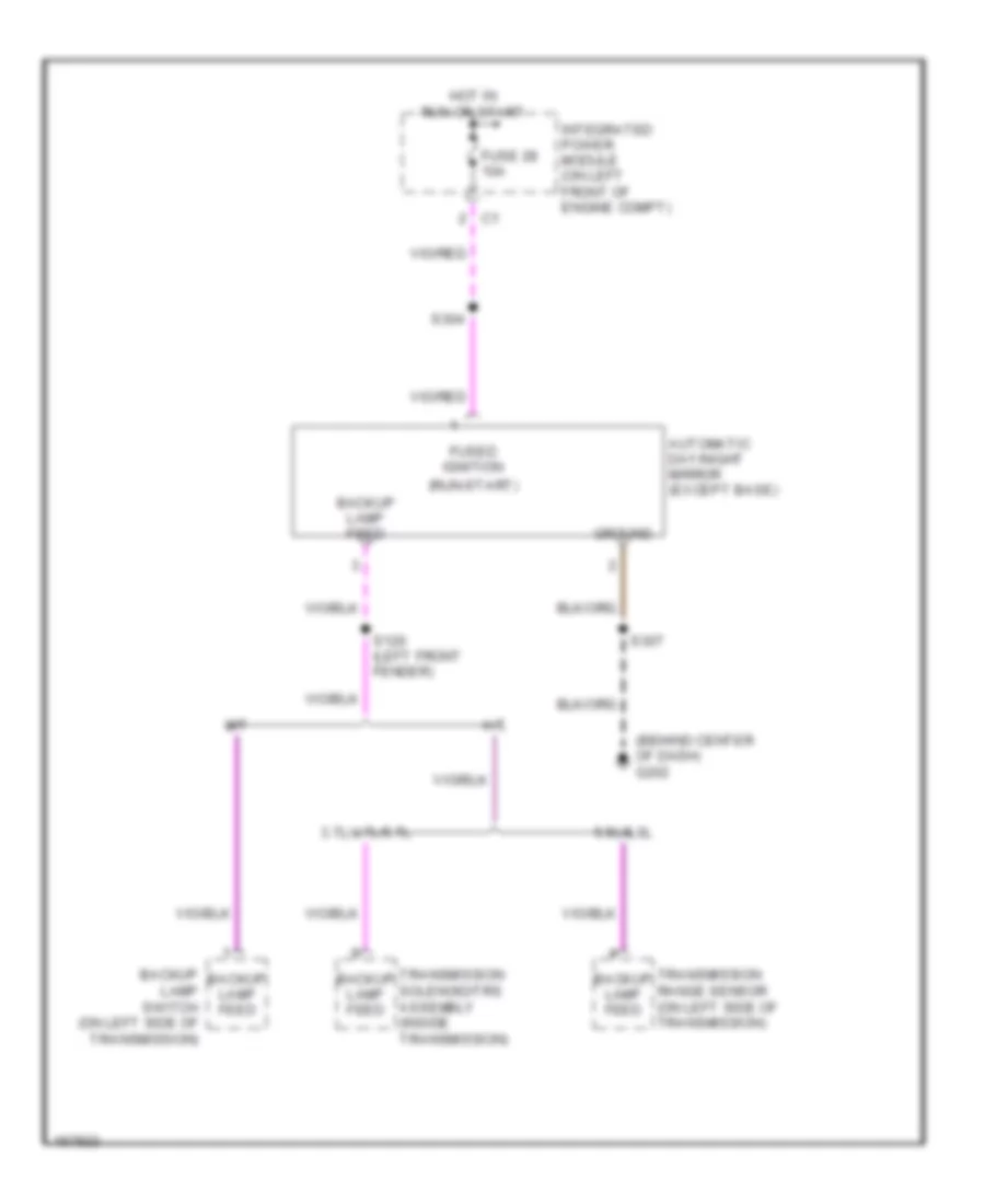
Back-up Lamps Wiring Diagram for Dodge Cab & Chassis R2003 3500
List of elements for Back-up Lamps Wiring Diagram for Dodge Cab & Chassis R2003 3500:
- (abs)
- (except abs)
- (left front of engine compt)
- A/t w/ 3.7l/4.7l/5.7l
- A/t w/ 5.9l/8.0l
- Add on trailer tow connector
- Automatic day/night mirror (except base)
- Back- up lamp
- Back-up lamp switch (on left side of transmission)
- Backup lamp feed
- Front control module
- Fuse 15a
- G103
- G104
- Hot in run
- Integrated power module (left front of engine compt)
- Left tail/stop/ turn signal lamp
- M/t
- Right tail/stop/ turn signal lamp
- S120 (left front fender)
- S308
- S325 (left rear chasis)
- Transmission range sensor (on left side of transmission)
- Transmission solenoid/trs assembly (inside transmission)
Exterior Lamps & Trailer connector Wiring Diagram for Dodge Cab & Chassis R2003 3500
List of elements for Exterior Lamps & Trailer connector Wiring Diagram for Dodge Cab & Chassis R2003 3500:
- (abs) (except abs)
- (below left side of dash) data link connector
- (center rear of chassis)
- (dual rear wheels)
- (left front of engine compt)
- (left front of engine compt) g104
- (left instrument panel) s231
- (left rear of chassis) s326
- (left rear of engine compt) s106
- (w/ tail lamp jumper)
- (w/ trailer tow connector add on)
- 87a
- Abs
- B(+)
- Back-up lamps circuit
- Brake lamp switch (above brake pedal, on support bracket)
- Brake sw input
- Center high mounted stop lamp (after- market)
- Center high mounted stop lamp/ cargo lamp
- D25
- Duty)
- Electric brake provision
- Except abs
- Fender lamp (dual rear wheels)
- Front control module
- Fuse 10a
- Fuse 15a
- Fuse 20a
- Fuse 40a
- Fuse 50a
- G103
- G103 (left front of engine compt)
- G104
- G104 g103 (left front of engine compt)
- G105 (on right front of chassis)
- G106 (left rear of engine compt)
- G202 (center of dash)
- Hazard
- Hdlp sw rtn
- Hdlp sw sig
- Head
- Headlamp switch
- Hot at all times
- Instrument cluster
- Integrated power module (left front of engine compt)
- L turn
- L22
- L24
- L60
- L61
- L62
- L63
- Left brake lp
- Left front fender lamp
- Left front park/ turn signal lamp
- Left license lamp
- Left rear fender lamp (dual rear wheels)
- Left tail/stop/ turn signal lamp
- Lf turn signal
- License lamp
- Lr turn signal
- Multi-function switch
- Off
- Park
- Park lamp relay
- Park rly ctrl
- Pci bus
- Ptc 7.5a
- R turn
- Rf turn signal
- Right
- Right brake lp
- Right front fender lamp
- Right front park/ turn signal lamp
- Right rear
- Right tail/ stop/ turn signal lamp
- Rr turn signal
- S101
- S102
- S108 (headlamp & dash, left side) (w/ add on trailer tow)
- S135
- S214 (behind left side of dash)
- S230 (right instrument panel)
- S308
- S309
- S324 (left rear of chassis)
- S327 (left rear of chassis) (w/ heavy
- S330
- S331
- S340
- S341
- S342
- S343
- Tail/ stop lamp
- Tail/ turn lamp
- Tailgate lamp assembly
- Tan/ red
- Trailer tow connector (beneath center of rear bumper)
- Trailer tow connector- add on
- Trailer tow left turn relay
- Trailer tow right turn relay
- Trlr l turn
- Trlr r turn
- Turn sw feed
- Turn sw sense
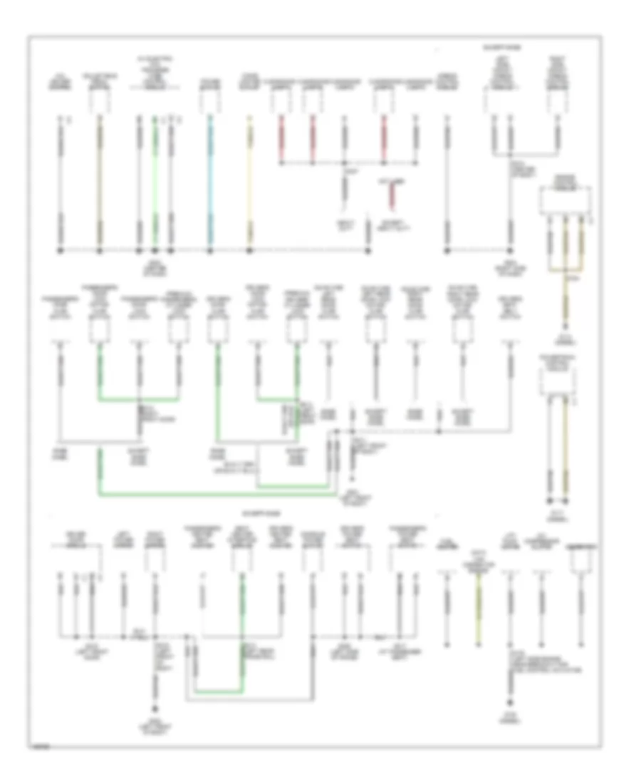
GROUND DISTRIBUTION
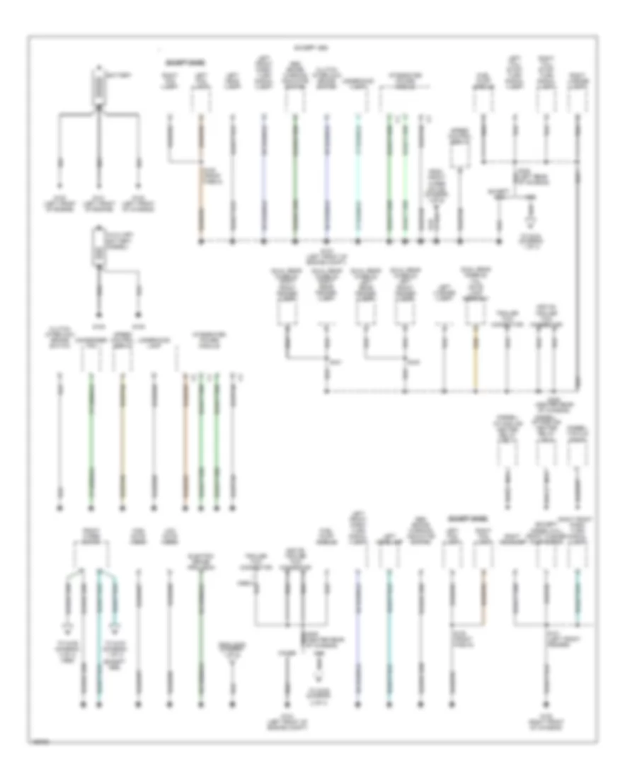
Ground Distribution Wiring Diagram (1 of 3) for Dodge Cab & Chassis R2003 3500
List of elements for Ground Distribution Wiring Diagram (1 of 3) for Dodge Cab & Chassis R2003 3500:
- (diesel) intake air heater relay no.1
- (diesel) intake air heater relay no.2
- (diesel) vacuum pump
- (dual rear wheels) left front fender lamp
- (dual rear wheels) left rear fender lamp
- (dual rear wheels) right front fender lamp
- (dual rear wheels) right rear fender lamp
- (dual rear wheels) tail gate lamp assembly
- (except abs)
- (except base)
- (except diesel/8.0l) front washer pump motor
- 2 of 3)
- Abs
- Add on trailer tow connector
- Auxiliary battery (diesel)
- Battery
- Clutch interlock brake switch
- Condenser fan
- Electric brake provision
- Except abs
- From front wiper motor (diagram 1 of 3)
- From s308 (diagram 1 of 3)
- Front wiper motor
- Fuel pump module
- G100 (left front of engine)
- G101 (left front of engine)
- G102 (left front of chassis)
- G103 (left front of engine compt)
- G104 (left front of engine compt)
- G105 (right front of chassis)
- G108
- G109
- High note horn
- Integrated power module
- Left fog lamp
- Left front park/ turn signal lamp
- Left head lamp
- Left headlamp
- Left license lamp
- Left tail/ stop/ turn signal lamp
- Low note horn
- Nca
- Other
- Red brake warning indicator switch
- Right fog lamp
- Right front park/ turn signal lamp
- Right headlamp
- Right license lamp
- Right tail/ stop/ turn signal lamp
- S101 (left front fender)
- S105 (front fascia)
- S308 (left rear of chassis)
- S309 (center rear of chassis)
- S340
- S341
- Speed control servo
- To g103 (diagram 1 of 3)
- To g104 (diagram 1 of 3)
- To g106 (diagram
- To g106 (diagram 2 of 3) (abs)
- Trailer tow connector
- Underhood lamp
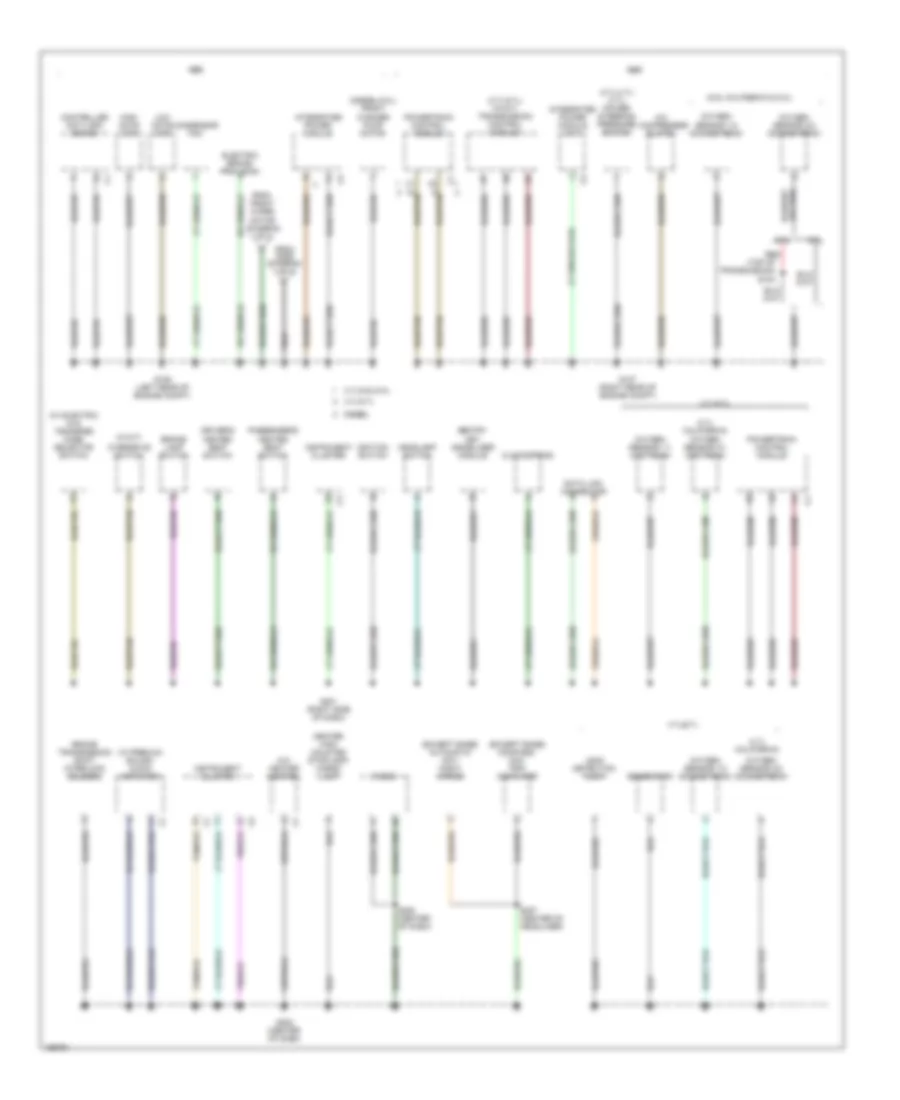
Ground Distribution Wiring Diagram (2 of 3) for Dodge Cab & Chassis R2003 3500
List of elements for Ground Distribution Wiring Diagram (2 of 3) for Dodge Cab & Chassis R2003 3500:
- (3.7l/4.7l/ 5.7l) power steering pressure switch
- (3.7l/5.7l) (w/a/t) transmission control module
- (4.7l california)
- (5.9l california & 8.0l)
- (diesel/8.0l) front washer pump motor
- (except base) automatic day/ night mirror
- (except base) compass/ mini- trip computer
- (top of transmission) s183
- (w/ electric 4x4) transfer case selector switch
- (w/ premium sound) audio amplifier
- (w/a/t)
- 3.7l/5.9l/8.0l
- 4.7l/5.7l
- 5.9l
- 8.0l
- A/c compressor clutch
- A/c- heater control
- Abs
- Brake lamp switch
- Brake transmission shift interlock solenoid
- Center high mounted stoplamp/ cargo lamp
- Clockspring
- Condensor fan
- Controller anti-lock brake
- Data link connector
- Diesel
- Driver's heated seat switch
- Electric brake provision
- From front wiper motor (diagram 1 of 3)
- From s309 (diagram 1 of 3)
- G106 (left rear of engine compt)
- G107 (right rear of engine compt)
- G201 (right side of dash)
- G202 (center of dash)
- Gas
- Generator
- Headlamp switch
- High note horn
- Ignition switch
- Instrument cluster
- Integrated power module
- Integrated power module (a/t)
- Leak detection pump
- Low note horn
- Overdrive switch
- Oxygen sensor 1/1 upstream
- Oxygen sensor 1/2 downstream
- Oxygen sensor 2/1 upstream
- Oxygen sensor 2/2 downstream
- Passenger's heated seat switch
- Powertrain control module
- Radio
- Red
- S208 (center of dash)
- S307 (center of headliner)
- Sentry key immobilizer module
Ground Distribution Wiring Diagram (3 of 3) for Dodge Cab & Chassis R2003 3500
List of elements for Ground Distribution Wiring Diagram (3 of 3) for Dodge Cab & Chassis R2003 3500:
- (diesel)
- (premium) driver's cylinder lock switch
- (premium) passenger's cylinder lock switch
- (quad cab) left rear door ajar switch
- (quad cab) left rear door lock motor/ ajar switch
- (quad cab) right rear door ajar switch
- (quad cab) right rear door lock motor/ ajar switch
- (w/ electric 4x4) transfer case control module
- A/c compressor clutch
- A/c- heater control
- Adjustable pedal switch
- Airbag control module
- Base model
- Cigar lighter outlet
- Clearance lamp 1
- Clearance lamp 2
- Clearance lamp 3
- Clearance lamp 4
- Clearance lamp 5
- Console power outlet
- Data link connector engine c
- Driver door module
- Driver's door ajar switch
- Driver's door lock motor/ ajar switch
- Driver's heated seat cushion
- Driver's power seat switch
- Driver's seat belt switch
- Engine control module
- Except base
- Except base model
- Except heavy duty
- Front door)
- Fuel heater
- G114 (diesel)
- G117
- G120
- G203 (center of dash)
- G204 (right side of dash)
- G301 (left front of body)
- G302 (left front of body)
- Generator
- Heavy duty
- Left power mirror
- Left side impact airbag control module
- Lift pump motor
- Passenger's door ajar switch
- Passenger's door lock motor/ ajar switch
- Passenger's door lock switch
- Passenger's heated seat cushion
- Passenger's power seat switch
- Power outlet
- Powertrain control module
- Right power mirror
- Right side impact airbag control module
- S164
- S176 (left side engine near breakout for fuel control actuator)
- S306 (left side of frame)
- S310 (center of body)
- S311 (left front of body)
- S315 (left front of body)
- S317 (at passenger seat)
- S319 (left front door)
- S337
- Seat heater interface module
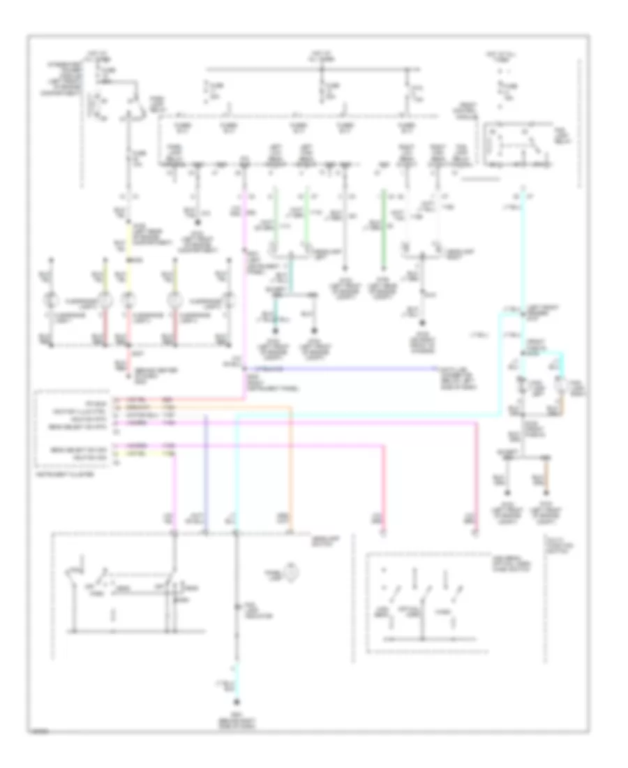
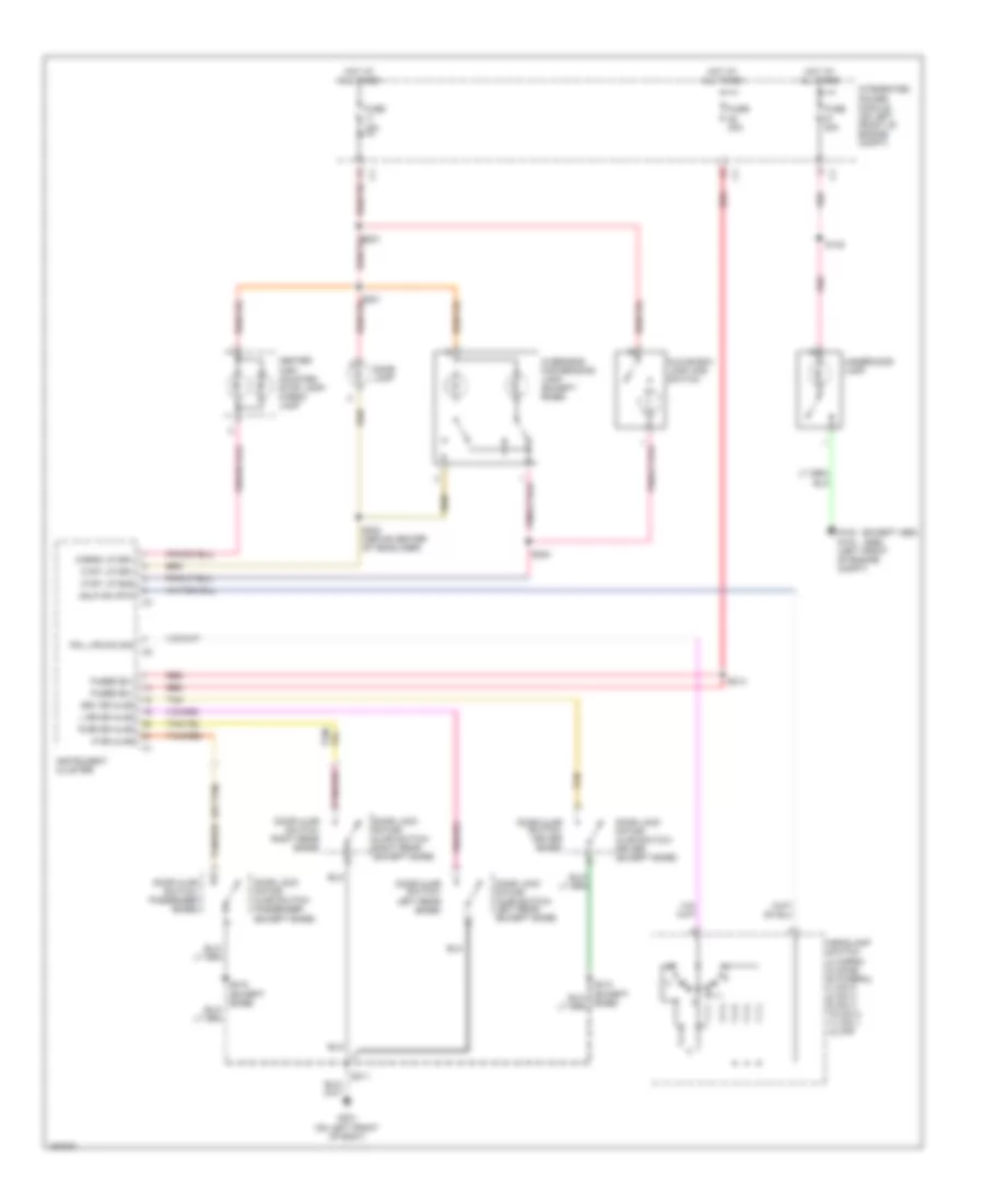
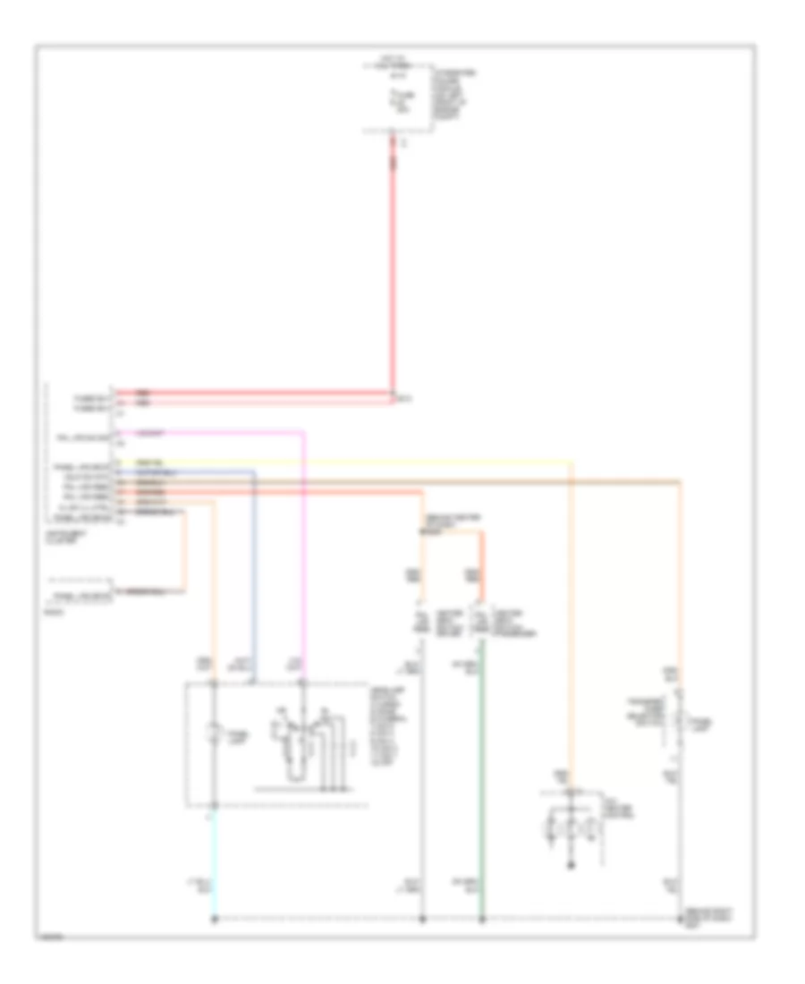
HEADLIGHTS
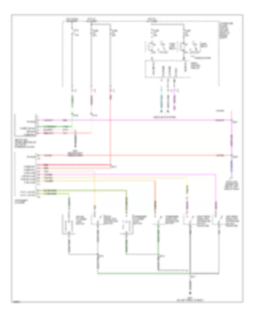
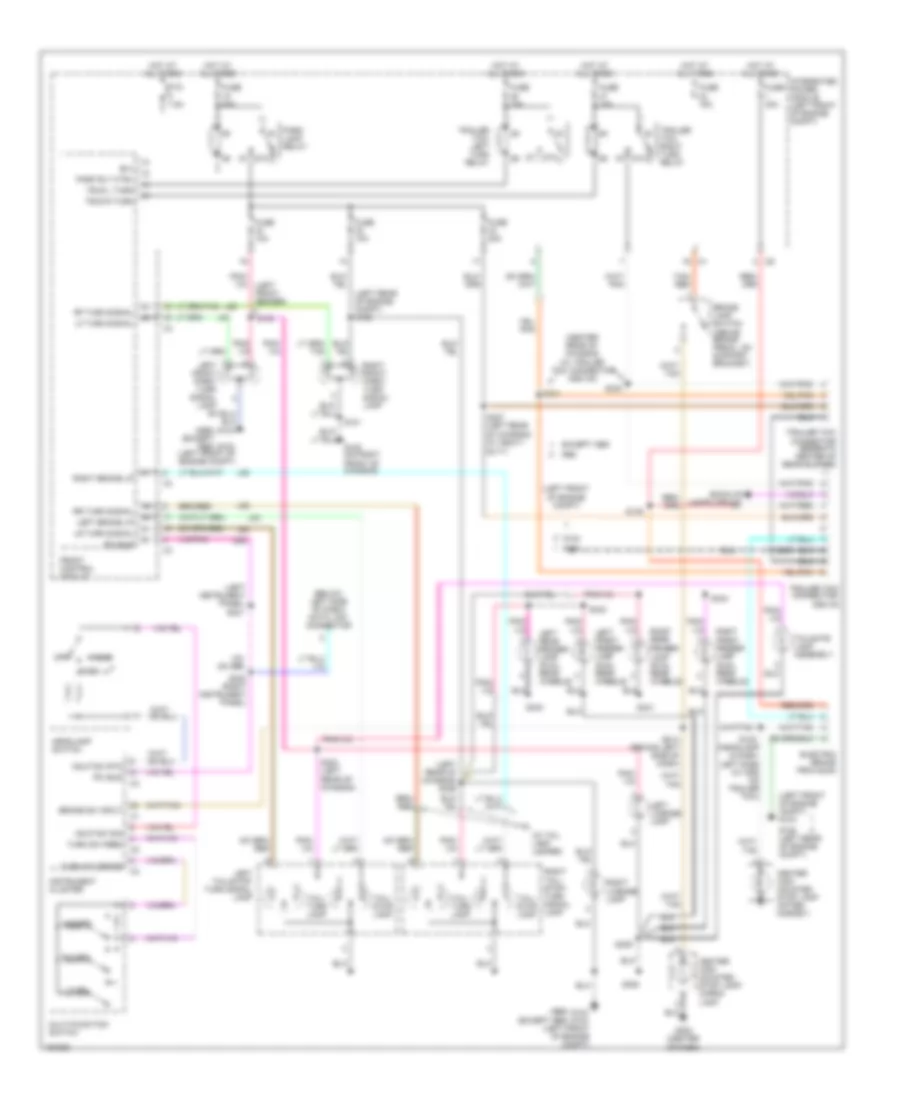
Headlights Wiring Diagram for Dodge Cab & Chassis R2003 3500
List of elements for Headlights Wiring Diagram for Dodge Cab & Chassis R2003 3500:
- (behind center of dash) g203
- (behind right side of dash)
- (front fascia) s104
- (left front fender) s107
- (left front of engine compt)
- (left rear of engine compartment)
- (right instrument panel)
- 87a
- Abs
- Beam select sw rtn
- Beam select sw sig
- Clearance lamp 1
- Clearance lamp 2
- Clearance lamp 3
- Clearance lamp 4
- Clearance lamp 5
- D25
- Data link connector (below left side of dash)
- Except abs
- Fog
- Fog lamp indicator
- Fog lamp left
- Fog lamp relay
- Fog lamp relay control
- Fog lamp right
- Front control module
- Fuse 10a
- Fuse 15a
- Fuse 30a
- Fuse 50a
- Fused b (+)
- G103 (left front of engine compartment)
- G103 (left front of engine compt)
- G104
- G104 (left front of engine compt)
- G105 (on right front of chassis)
- G106 (left rear of engine compt)
- G201
- Gnd
- Hdlp sw illum ctrl
- Hdlp sw rtn
- Hdlp sw sig
- Head
- Headlamp left
- Headlamp right
- Headlamp switch
- High beam
- High beam/ optical horn/ wash switch
- Hot at all times
- Instrument cluster
- Integrated power module (left front of engine compartment)
- Left high beam output
- Left low beam output
- Multi- function switch
- Off
- Optical horn
- Panel lamp
- Park
- Park lamp relay
- Park lamp relay control
- Pci bus
- Ptc 7.5a
- Right high beam output
- Right low beam output
- S101
- S105 (front fascia)
- S106
- S230
- S231 (left instrument panel)
- S336
- S337
- Wash
- Y108
- Y109
- Y126
- Y163
- Y167
- Y168
- Y169
- Y170
- Y171
- Z12
- Z21
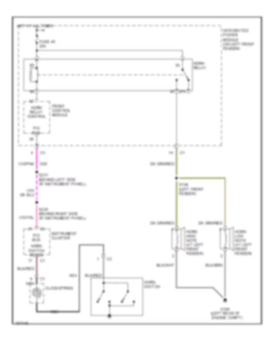
HORN
Horn Wiring Diagram for Dodge Cab & Chassis R2003 3500
List of elements for Horn Wiring Diagram for Dodge Cab & Chassis R2003 3500:
- 87a
- Clockspring
- D25
- Front control module
- Fuse 45 20a
- G106 (left rear of engine compt)
- Horn high note (at left front fender)
- Horn low note (at left front fender)
- Horn relay
- Horn relay control
- Horn switch
- Horn switch sense
- Hot at all times
- Instrument cluster
- Integrated power module (on left front fender)
- Nca
- Pci bus
- S109 (left front fender)
- S230 (behind right side of instrument panel)
- S231 (behind left side of instrument panel)
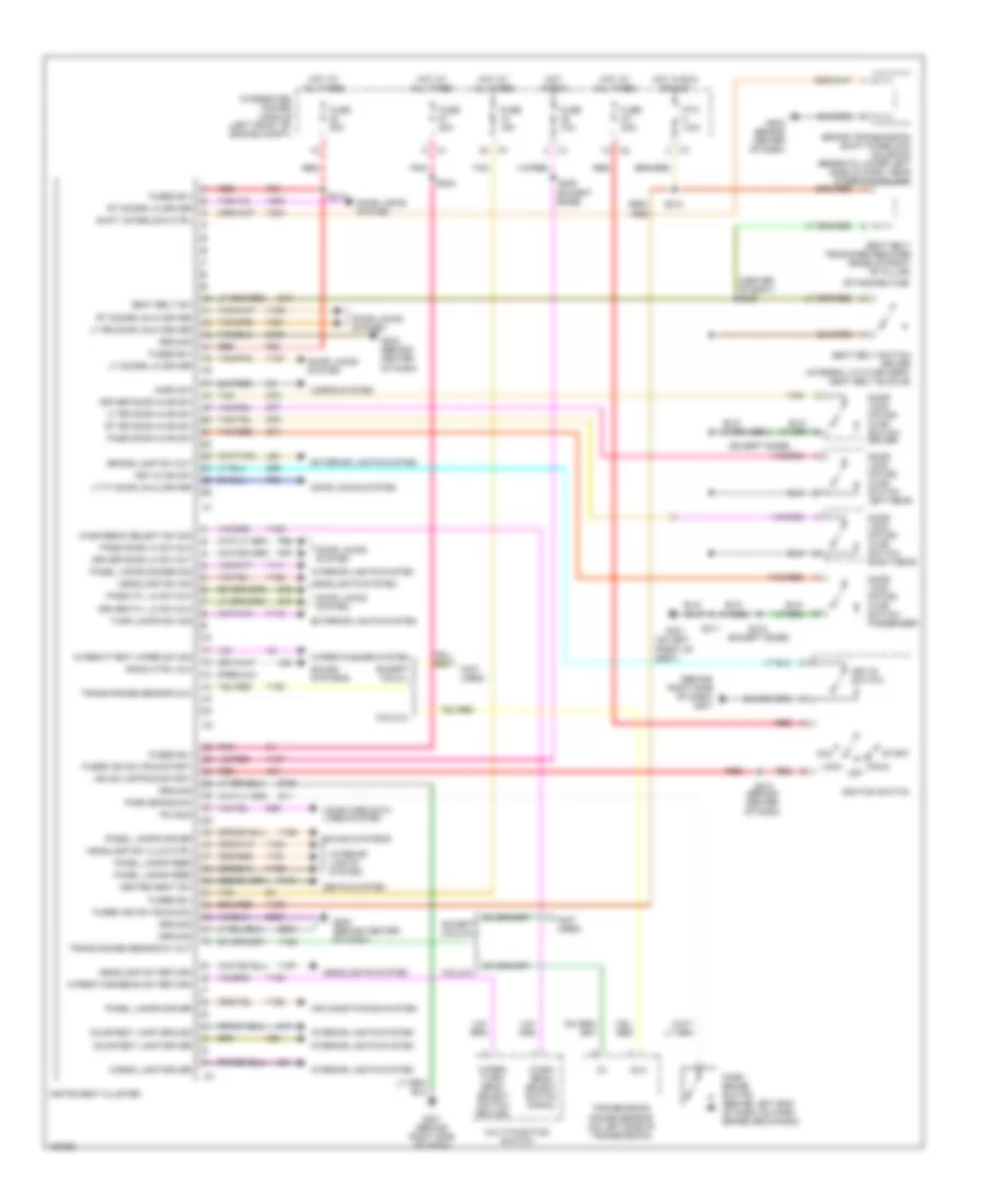
INSTRUMENT CLUSTER
Instrument Cluster Wiring Diagram for Dodge Cab & Chassis R2003 3500
List of elements for Instrument Cluster Wiring Diagram for Dodge Cab & Chassis R2003 3500:
- (behind center of dash)
- (behind right side of dash) g201
- (center of body) s320
- (except base)
- (not used)
- (on left front of body)
- (premium)
- (standard cab)
- 5.9l/8.0l
- A51
- Acc
- Air conditioning system
- Brake lamp sw out
- Brake transmission shift interlock solenoid (beneath lower left side of dash, near steering column)
- Cargo lamp driver
- Computer data lines system
- Courtesy lamp driver
- Courtesy lamp ground
- D25
- Door lock motor/ ajar switch driver
- Door lock motor/ ajar switch left rear
- Door lock motor/ ajar switch passenger
- Door lock motor/ ajar switch right rear
- Door locks system
- Driver cyl lk sw mux
- Driver door ajar sw
- Driver door lk sw out
- Except 5.9l/8.0l
- Except 5.9l/8.l
- Exterior lights system
- F35
- Fuse 10a
- Fuse 15a
- Fuse 20a
- Fuse 25a
- Fused b(+)
- Fused ign sw (run/acc)
- Fused ign sw (run/start)
- G10
- G11
- G201 (behind right side of dash)
- G202 (behind center of dash)
- G26
- G301
- G72
- G73
- G74
- G75
- G76
- G77
- Ground
- Headlamp sw illum ctrl
- Headlamp sw return
- Headlamp sw sig
- Headlights system
- Heated seat sw
- Horn sw
- Horns system
- Hot at all times
- Hot in run
- Hot in run or acc
- Ign sw (off/run/start)
- Ignition switch
- Instrument cluster
- Integrated power module (left front of engine compt)
- Interior lights system
- Intermittent wiper sw sig
- Key-in ign sw
- Key-in switch
- L50
- Lock
- Lt doors lk driver
- Lt ft door unlk driver
- Lt rr door ajar sw
- Lt rr door unlk driver
- M11
- M20
- Multi-function switch
- Mux
- Off
- P131
- P55
- P96
- P97
- Panel lamps dimmer sig
- Panel lamps dirver
- Panel lamps feed
- Park brake sw
- Park brake switch (behind left end of dash, on park brake mechanism)
- Pass cyl lk sw mux
- Pass door ajar sw
- Pass door lk sw mux
- Pci bus
- Pnk
- Ptc 4.5a
- Radio ctrl mux
- Red
- Rt doors lk driver
- Rt doors unlk driver
- Rt rr door ajar sw
- Run
- S204
- S205 (except base)
- S210
- S212
- S213
- S311
- S312
- S313
- Seat belt sw
- Seat belt switch driver (integral with driver's seat belt buckle)
- Seat belt tensioner reducer (base of right "b" pillar)
- Seats system
- Shift iinterlock ctrl
- Sound systems
- Sound systems
- Start
- Tan
- Tan/pnk
- Tan/red
- Trans range sensor 5v out
- Trans range sensor mux
- Transmission range sensor (on left side of transmission)
- Turn lamps sw sig
- Wash/ beam select switch signal
- Wash/beam select sw sig
- Wiper/ turn/ beam select switch return
- Wiper/turn/beam sw return
- Wiper/washer system
- X20
- Y105
- Y107
- Y108
- Y109
- Y110
- Y111
- Y126
- Y128
- Y156
- Y157
- Y161
- Y163
- Y165
- Y166
- Y167
- Y189
- Y193
- Y200
- Y201
- Y204
- Z105
- Z106
- Z202
- Z203
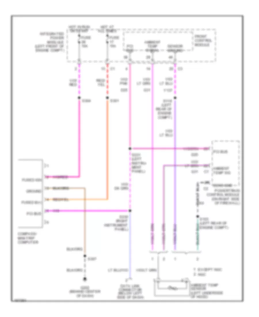
Overhead Console Wiring Diagram for Dodge Cab & Chassis R2003 3500
List of elements for Overhead Console Wiring Diagram for Dodge Cab & Chassis R2003 3500:
- Ambient temp sensor (left underside of hood)
- Ambient temp sig
- Ambient temp signal
- Compass/ mini-trip computer
- D25
- Data link connector (below left side of dash)
- Except ngc
- Front control module
- Fuse 10a
- Fuse 15a
- Fused b(+)
- Fused ign
- G202 (behind center of dash)
- G31
- Ground
- Hot at all times
- Hot in run or start
- Integrated power modlule (left front of engine compt)
- Ngc
- Pci bus
- Powertrain control module (on right side of firewall)
- S103 (left rear of engine compt)
- S119 (left rear of engine compt)
- S230 (right instrument panel)
- S231 (left instru- ment panel)
- S301
- S304
- S307
- Sens gnd
- Sensor ground
- Y137
INTERIOR LIGHTS
Courtesy Lamps Wiring Diagram for Dodge Cab & Chassis R2003 3500
List of elements for Courtesy Lamps Wiring Diagram for Dodge Cab & Chassis R2003 3500:
- (except abs) (abs)
- (or tan)
- Cargo lp drv
- Center high mounted stop lamp/ cargo lamp
- Ctsy lp drv
- Ctsy lp gnd
- Dome lamp
- Door ajar switch- driver (base)
- Door ajar switch- left rear (base)
- Door ajar switch- passenger (base)
- Door ajar switch- right rear (base)
- Door lock motor/ ajar switch- driver (except base)
- Door lock motor/ ajar switch- left rear (except base)
- Door lock motor/ ajar switch- passenger (except base)
- Door lock motor/ ajar switch- right rear (except base)
- Drv dr ajar
- Fuse 15a
- Fuse 20a
- Fused b(+)
- G103 g104 (left front of engine compt)
- G301 (on left front of body)
- Glove box lamp and switch
- Hdlp sw rtn
- Headlamp switch 4) cargo 5) dome 6) funeral 7) dim 5 8) dim 4 9) dim 3 10) dim 2 11) dim 1 12) off
- Hot at all times
- Instrument cluster
- Integrated power module (on left front of engine compt)
- L rr dr ajar
- Overhead map/reading lamp (except base)
- P dr ajar
- Pnk
- Pnl lps dim sig
- R rr dr ajar
- Red
- S145
- S202
- S213
- S302 (above center of headliner)
- S311
- S312 (except base)
- Tan
- Tan/red
- Underhood lamp
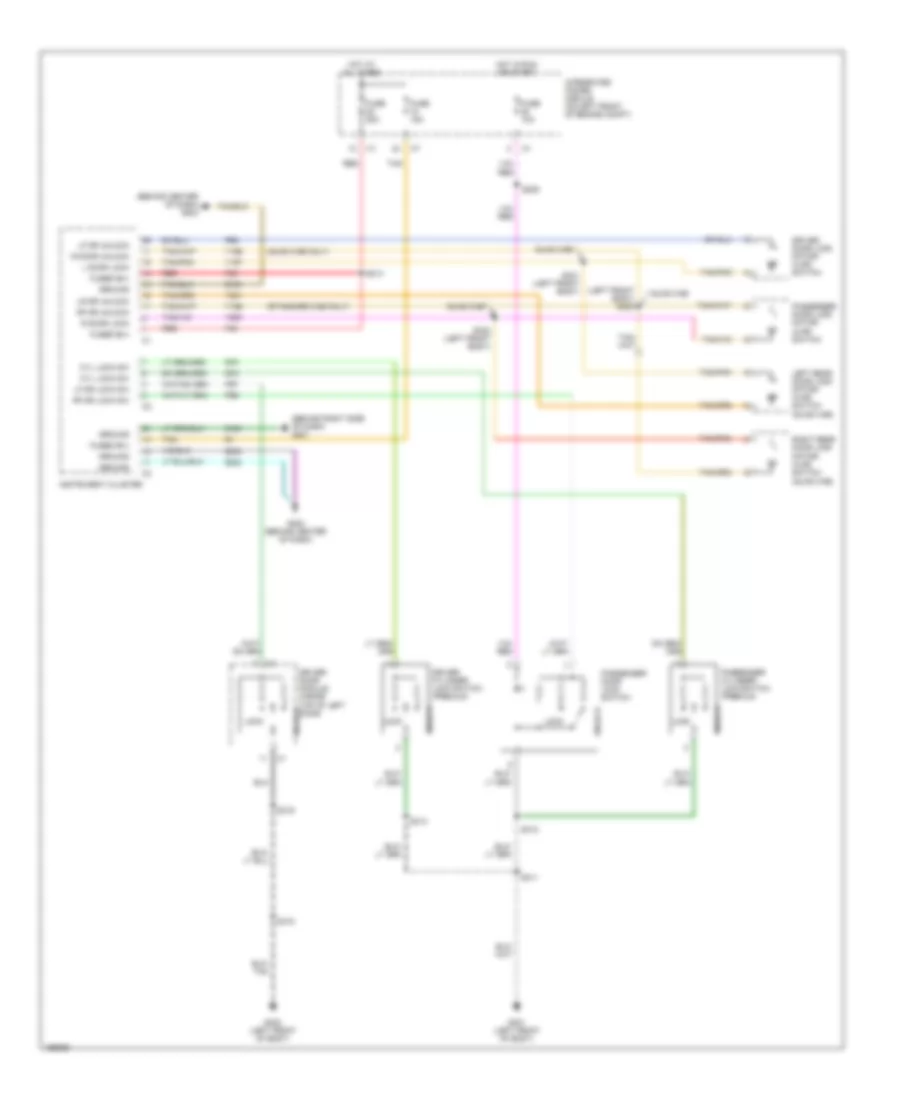
Instrument Illumination Wiring Diagram for Dodge Cab & Chassis R2003 3500
List of elements for Instrument Illumination Wiring Diagram for Dodge Cab & Chassis R2003 3500:
- (behind center of dash) s209
- (behind right side of dash) g201
- A/c- heater control
- Fuse 20a
- Fused b(+)
- Hdlp sw rtn
- Headlamp switch 4) cargo 5) dome 6) funeral 7) dim 5 8) dim 4 9) dim 3 10) dim 2 11) dim 1 12) off
- Heated seat switch- driver
- Heated seat switch- passenger
- Hl sw ill ctrl
- Hot at all times
- Instrument cluster
- Integrated power module (on left front of engine compt)
- Panel lamp
- Panel lps drvr
- Pnl lps dim sig
- Pnl lps feed
- Radio
- Red
- S213
- Transfer case selector switch
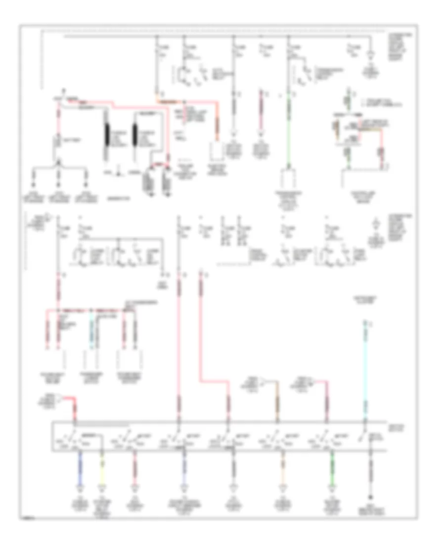
POWER DISTRIBUTION
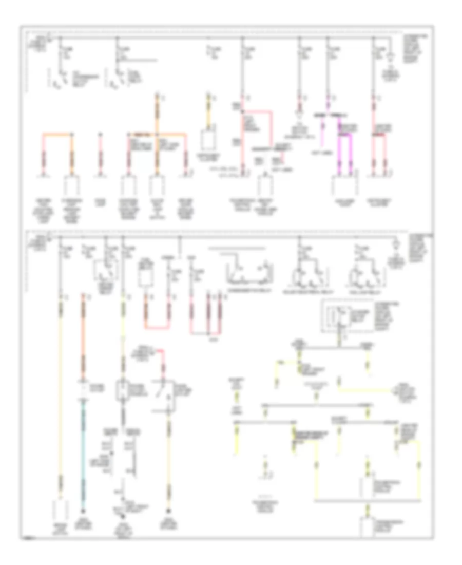
Power Distribution Wiring Diagram (1 of 4) for Dodge Cab & Chassis R2003 3500
List of elements for Power Distribution Wiring Diagram (1 of 4) for Dodge Cab & Chassis R2003 3500:
- (at passenger's seat) s318
- (left rear of engine compt) s114
- (not used)
- (quad cab)
- (standard cab)
- Abs
- Acc
- Auto shutdown relay
- Battery
- Battery auxiliary
- Controller anti-lock brake
- Diesel
- Electric brake provision
- From c fuse 6 (diagram 1 of 4)
- From fuse 20 l (diagram 2 of 4)
- From fuse 3 a (diagram 1 of 4)
- From fuse 4 b (diagram 1 of 4)
- Front control module
- Fuse 30a
- Fuse 40a
- Fuse 50a
- G100 (left front of engine)
- G101 (left front of engine)
- G102 (left front of chassis)
- G201 (behind right side of dash)
- Gas
- Generator
- Ignition switch
- Instrument cluster
- Integrated power module (on left front of engine compt)
- Key-in switch
- Lock
- Off
- Park lamp relay
- Passenger lumbar switch
- Power seat passenger switch
- Power seat switch driver
- Red
- Red/
- Run
- Rwal
- S316 (at driver's seat)
- Start
- Starter motor relay
- To blower motor (diagram 4 of 4)
- To fuse 16 (diagram 2 of 4)
- To fuse 28 (diagram 3 of 4)
- To fuse 52 (diagram 4 of 4)
- To fuse 7 (diagram 1 of 4)
- To ignition switch (diagram 1 of 4)
- To power window circuit breaker (diagram 4 of 4)
- To ptc 2 (diagram 4 of 4)
- To s210 (diagram 4 of 4)
- To starter motor relay (diagram 2 of 4)
- Trailer tow connector- add on
- Trailer tow except diesel/8.0l
- Transmission control module (3.7l & 4.7l w/a/t)
- Transmission control relay
- Wiper high/ low relay
- Wiper on/ off relay
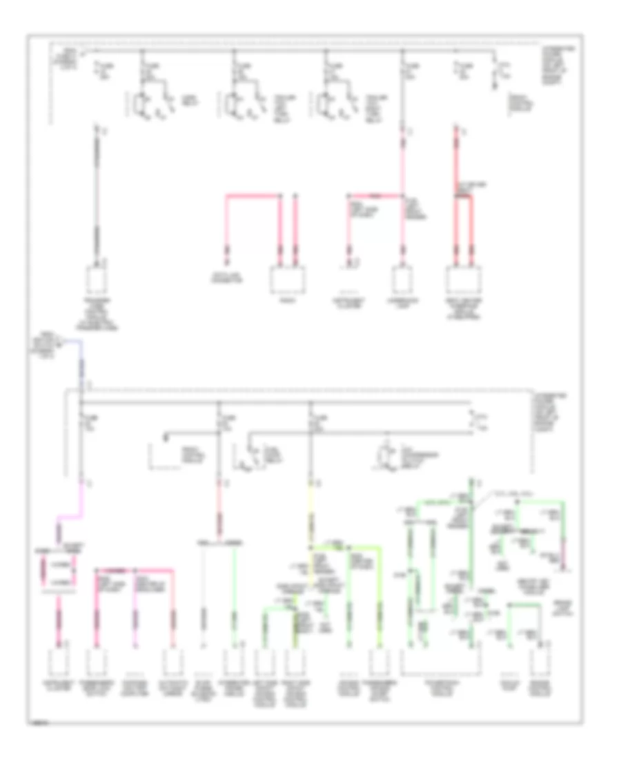
Power Distribution Wiring Diagram (2 of 4) for Dodge Cab & Chassis R2003 3500
List of elements for Power Distribution Wiring Diagram (2 of 4) for Dodge Cab & Chassis R2003 3500:
- (3.7l, 5.9l, 8.0l)
- (4.7l, 5.7l)
- (center rear of engine compt) s126
- (center of dash) s213
- (diagram 1 of 4)
- (left side of frame)
- (not used)
- 3.7l
- 3.7l/4.7l/5.7l w/a/t
- 4.7l/5.7l
- 5.7l a/t
- 87a
- A/c compressor clutch relay
- A/t
- Adjustable pedal relay
- Amplifier audio
- Base
- Brake lamp switch
- Center high mounted stoplamp/ cargo lamp
- Cigar lighter- outlet
- Compass/ mini-trip computer (except basae)
- Condenser fan relay
- Diesel
- Diesel/ 8.0l
- Dome lamp
- Driver door module (except base)
- Except 5.7l a/t
- Except 5.9l w/a/t
- Except security
- Fog lamp relay
- From d fuse 15 (diagram 1 of 4)
- From fuse 29 o (diagram 4 of 4)
- From ignition switch f
- From m fuse 22 (diagram 2 of 4)
- Fuel heater relay
- Fuel pump relay
- Fuse 10a
- Fuse 15a
- Fuse 20a
- Fuse 25a
- Fuse 30a
- Fuse 40a
- G203 (center of dash)
- G302 (on left front of body)
- Gas
- Gas except 8.0l
- Glove box lamp & switch
- Heated mirror relay
- Instrument cluster
- Integrated power module (on left front of engine compt)
- M/t
- Manual seats
- Overhead map/ reading lamp (except base)
- Power outlet
- Power outlet- console
- Power seats
- Powertrain control module
- Premium
- Red
- Red/tan
- S110 (left front fender)
- S191
- S201 (left side of dash)
- S301 (center of headliner)
- S306
- Security
- Sentry key immobilizer module
- Starter motor relay
- Tan
- Tan/red
- To fuse 24 (diagram 2 of 4)
- To fuse 43 (diagram 3 of 4)
- To ignition switch (diagram 1 of 4)
- Transmission control module
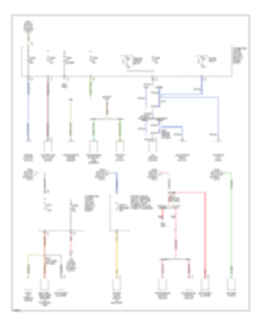
Power Distribution Wiring Diagram (3 of 4) for Dodge Cab & Chassis R2003 3500
List of elements for Power Distribution Wiring Diagram (3 of 4) for Dodge Cab & Chassis R2003 3500:
- (3.7l, 5.9l, 8.0l)
- (4.7l, 5.7l)
- (at driver seat) s328
- (left front fender)
- 4.7l
- 5.7l
- A/c compressor clutch relay
- Air bag control module
- Automatic day/night mirror
- Base
- Brake lamp switch
- Compass/ mini-trip computer
- Data link connector
- Diesel
- Engine control module
- Evap/ purge solenoid (jtec)
- Except base
- Except diesel
- Except security
- Except side impact airbags
- From ignition switch (diagram 1 of 4)
- From n fuse 41 (diagram 2 of 4)
- Front control module
- Fuel pump relay
- Fuse 10a
- Fuse 15a
- Fuse 20a
- Fuse 25a
- Gas
- Horn relay
- Instrument cluster
- Integrated power module
- Integrated power module (on left front of engine compt)
- Left side impact air bag control module
- Not used
- Passenger's air bag on/off switch
- Passenger's door lock switch
- Pnk
- Powertrain control module
- Ptc 7.5a
- Radio
- Red
- Right side impact air bag control module
- S136
- S145 (left front fender)
- S186
- S204 (left side of dash)
- S205 (left side of dash)
- S222 (center of dash)
- S304 (center of headliner)
- S335 (left front body)
- Seat heater interface module (if equipped)
- Security
- Sentry key immobilizer module
- Side impact airbags
- Trailer tow left turn relay
- Trailer tow right turn relay
- Transfer case control module (w/ electric transfer case)
- Underhood lamp
- Vacuum pump
Power Distribution Wiring Diagram (4 of 4) for Dodge Cab & Chassis R2003 3500
List of elements for Power Distribution Wiring Diagram (4 of 4) for Dodge Cab & Chassis R2003 3500:
- (not used)
- 3.7l/4.7l/ 5.7l
- 3.7l/5.7l
- 4.7l
- 5.9l
- 5.9l/8.0l/ diesel
- A/c- heater control
- A/t
- Adjustable pedal
- Adjustable pedal switch
- Air bag control module
- Back-up lamp switch
- Blower motor
- Circuit breaker 25a
- Controller anti-lock brake
- Diesel
- Driver door module (if equipped)
- Except 5.9l
- Except adjustable pedal
- From ignition switch (diagram 1 of 4)
- Fuse (spare)
- Fuse 10a
- Fuse 15a
- Fuse 20a
- Gas
- Heated mirror relay
- Instrument cluster
- Integrated power module (on left front of engine compt)
- M/t
- Not used
- Power window circuit breaker (below left side of dash, near steering column, taped to harness)
- Powertrain control module
- Ptc 4.5a
- Radio (w/ premium sound)
- Red
- S140
- S210 (center of dash)
- S212 (left side of dash)
- S225 (behind center of dash)
- Seat belt tensioner reducer (w/ standard cab)
- Spare relay
- Tan
- To cigar lighter outlet (diagram 2 of 4)
- Transmission control module
- Transmission range sensor
- Transmission solenoid/ trs assembly
- Vistronic fan drive
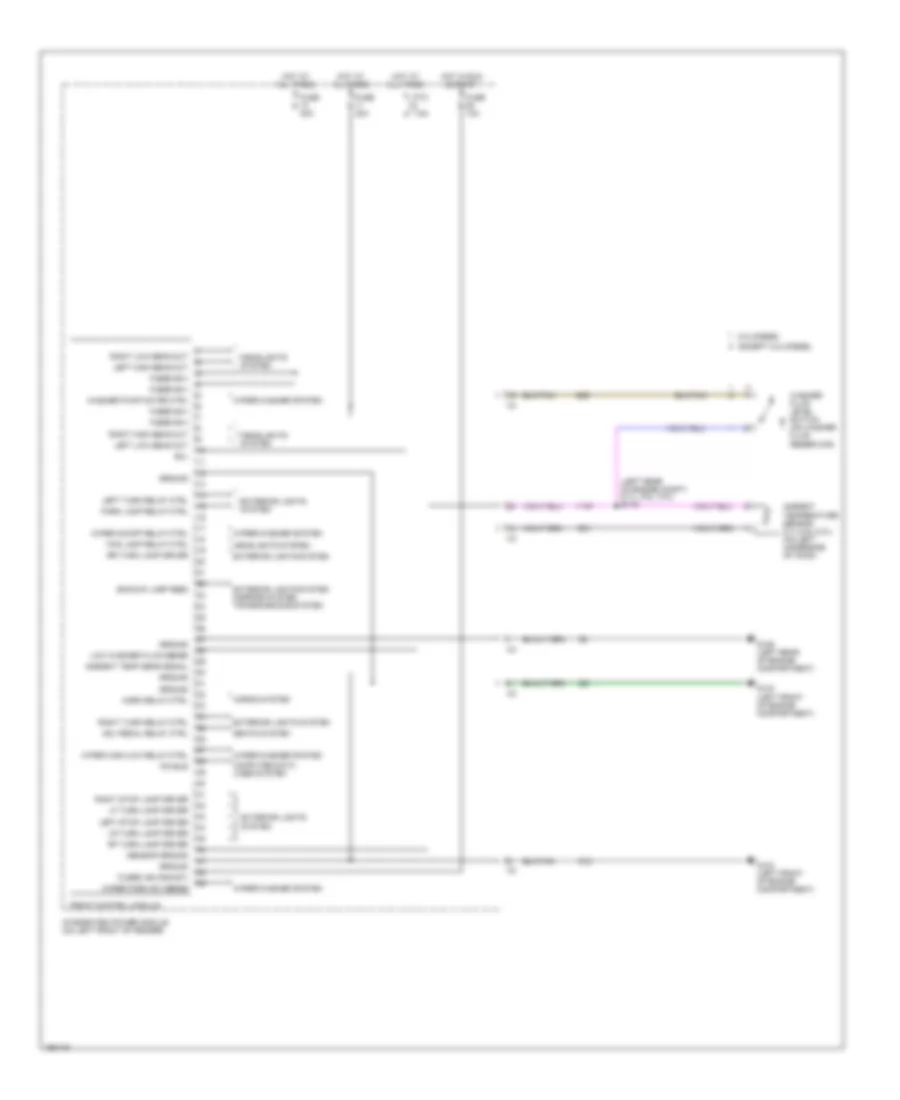
POWER DOOR LOCKS
Power Door Locks Wiring Diagram for Dodge Cab & Chassis R2003 3500
List of elements for Power Door Locks Wiring Diagram for Dodge Cab & Chassis R2003 3500:
- (behind center of dash) g202
- (behind right side of dash) g201
- (left front body) s323
- (quad cab only)
- (quad cab)
- (standard cab only)
- Cyl lock sw
- Driver cylinder lock switch (premium)
- Driver door lock motor/ ajar switch
- Driver door module (inside top of left door)
- F35
- Fuse 10a
- Fuse 15a
- Fuse 20a
- Fused b(+)
- G202 (behind center of dash)
- G301 (left front of body)
- G302 (left front of body)
- G72
- G73
- Ground
- Hot at all times
- Hot in run or start
- Instrument cluster
- Integrated power module (on left front of engine compt)
- L door lock
- Left rear door lock motor/ ajar switch
- Lf dr lock sw
- Lf dr unlock
- Lock
- Lr dr unlock
- P55
- P96
- P97
- Passenger cylinder lock switch (premium)
- Passenger door lock motor/ ajar switch
- Passenger door lock switch
- Quad cab
- R door lock
- R door unlock
- Red
- Rf dr lock sw
- Rf dr unlock
- Right rear door lock motor/ ajar switch
- S205
- S213
- S311
- S312
- S313
- S315
- S319
- S321 (left front body)
- S322 (left front body)
- Tan
- Tan/pnk
- Unlock
- Y156
- Y157
- Y200
- Y201
- Z105
- Z106
- Z202
- Z203
POWER MIRRORS
Automatic Day/Night Mirror Wiring Diagram for Dodge Cab & Chassis R2003 3500
List of elements for Automatic Day/Night Mirror Wiring Diagram for Dodge Cab & Chassis R2003 3500:
- (behind center of dash) g202
- (run-start)
- 3.7l/4.7l/5.7l
- 5.9l/8.0l
- A/t
- Automatic day/night mirror (except base)
- Backup lamp feed
- Backup lamp switch (on left side of transmission)
- Fuse 28 10a
- Fused ignition
- Ground
- Hot in run or start
- Integrated power module (on left front of engine compt)
- M/t
- S120 (left front fender)
- S304
- S307
- Transmission range sensor (on left side of transmission)
- Transmission solenoid/trs assembly (inside transmission)
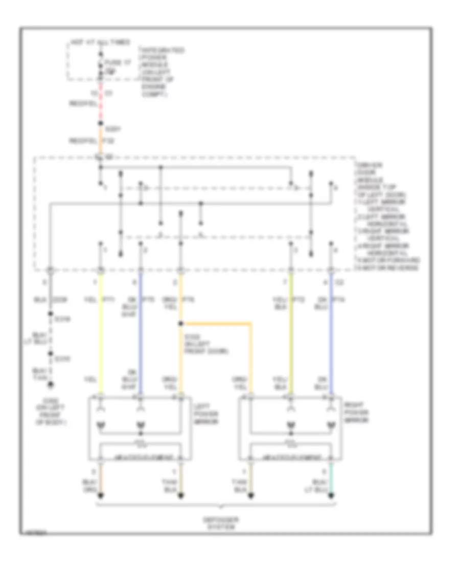
Power Mirrors Wiring Diagram for Dodge Cab & Chassis R2003 3500
List of elements for Power Mirrors Wiring Diagram for Dodge Cab & Chassis R2003 3500:
- 2 left mirror
- 3 right mirror
- 4 right mirror
- 5 motor forward 6 motor reverse
- Defogger system
- Dk p74
- Dk p75
- Driver door module (inside top of left door) 1 left mirror
- Fuse 17 15a
- G302 (on left front of body)
- Heated element
- Horizontal
- Hot at all times
- Integrated power module (on left front of engine compt)
- Left power mirror
- Right power mirror
- S201
- S315
- S319
- S332 (in left front door)
- Vertical
POWER SEATS
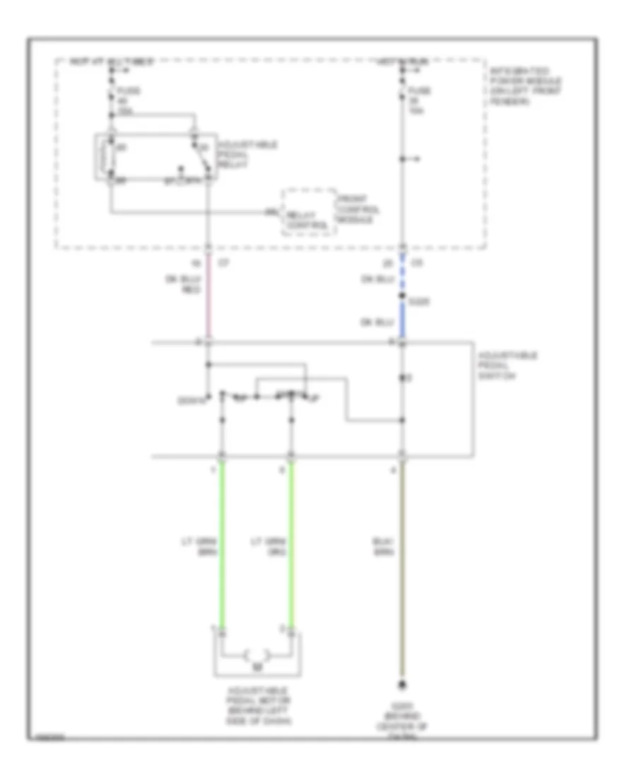
Adjustable Pedal Wiring Diagram for Dodge Cab & Chassis R2003 3500
List of elements for Adjustable Pedal Wiring Diagram for Dodge Cab & Chassis R2003 3500:
- 87a
- Adjustable pedal motor (behind left side of dash)
- Adjustable pedal relay
- Adjustable pedal switch
- Down
- Front control module
- Fuse 10a
- Fuse 15a
- G203 (behind center of dash)
- Hot at all times
- Hot in run
- Integrated power module (on left front fender)
- Relay control
- S225
Heated Seats Wiring Diagram for Dodge Cab & Chassis R2003 3500
List of elements for Heated Seats Wiring Diagram for Dodge Cab & Chassis R2003 3500:
- (behind center of dash) s209
- (driver's seat) s329
- Driver heated seat cushion
- Driver heated seat switch
- Driver st htr mux sw
- Driver st temp 5v sply
- Driver st temp sens in
- Drv st hi heat led drv
- Drv st lo heat led drv
- F235
- Fuse 20a
- Fused b(+)
- G201 (behind right side of dash)
- G302 (on left front of body)
- Ground
- Heater mux sw
- High heat led
- Hot at all times
- Ht st sw sply
- Instrument cluster
- Integrated power module (on left front fender)
- Low heat led
- P131
- P133
- P134
- P137
- P138
- P139
- P140
- P141
- P142
- P143
- P144
- P86
- Panel lamps feed
- Panel lmp feed
- Pass st hi heat led drv
- Pass st htr mux sw
- Pass st lo heat led drv
- Pass st temp 5v sply
- Pass st temp sens in
- Passenger heated seat cushion
- Passenger heated seat switch
- Red
- S216 (behind center of dash)
- S314
- S328
- Seat heater interface module (under driver's seat)
- Seat htr driver
- Temp sens input
- Temp sns input
- Y161
- Z121
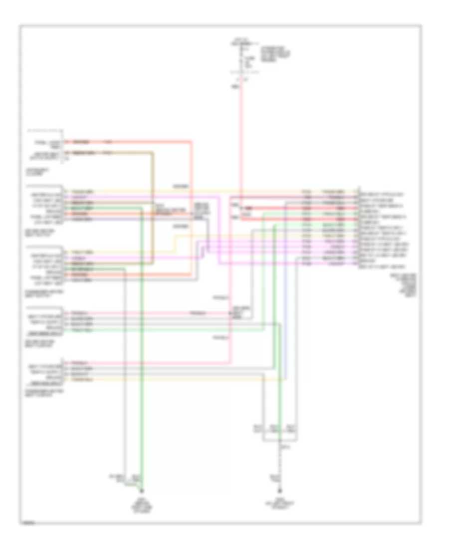
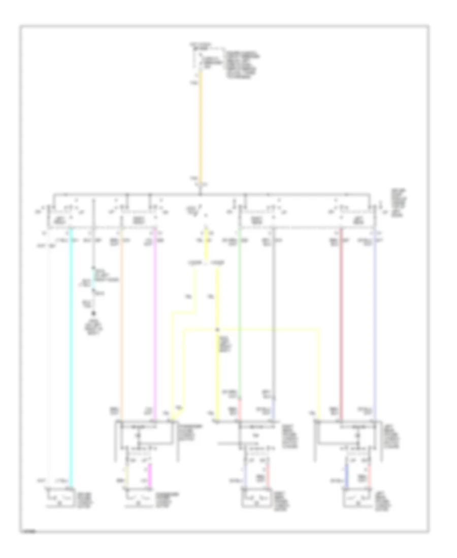
Power Seats Wiring Diagram for Dodge Cab & Chassis R2003 3500
List of elements for Power Seats Wiring Diagram for Dodge Cab & Chassis R2003 3500:
- Driver front vertical power seat motor
- Driver horizontal power seat motor
- Driver lumbar motor
- Driver rear vertical power seat motor
- F dn
- F up
- Forward
- Fuse 50a
- Fwd
- G302 (on left front of body)
- Hot at all times
- Integrated power module (on left front of engine compt)
- Nca
- Passenger front vertical power seat motor
- Passenger horizontal power seat motor
- Passenger lumbar motor
- Passenger lumbar switch
- Passenger power seat switch
- Passenger rear vertical power seat motor
- Power seat switch driver
- Quad cab
- R dn
- R up
- Rearward
- Rwd
- S306
- S316
- S317
- S318
- Standard cab
POWER WINDOWS
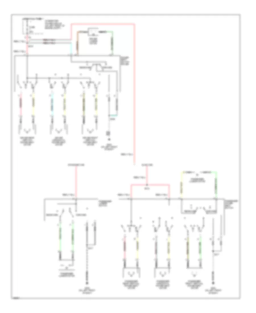
Power Windows Wiring Diagram for Dodge Cab & Chassis R2003 3500
List of elements for Power Windows Wiring Diagram for Dodge Cab & Chassis R2003 3500:
- 2 door
- 4 door
- Circuit breaker 25a
- Driver door module (inside top of left door)
- Driver power window motor
- G302 (on left front of body)
- Hot in run or acc
- Left front
- Left rear
- Left rear power window motor
- Left rear power window switch (4 door)
- Lock out
- Passenger
- Passenger power window motor
- Power window circuit breaker (below left side of dash, near steering column, taped to harness)
- Power window switch
- Q18
- Q26
- Right front
- Right rear
- Right rear power window motor
- Right rear power window switch (4 door)
- S315
- S333 (left front body)
- Tan
- Z67
RADIO
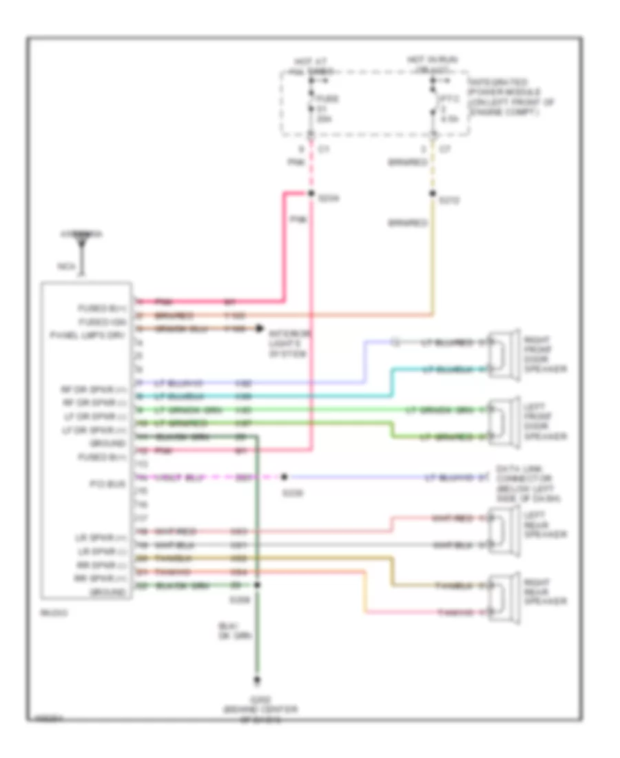
Radio Wiring Diagram, Base Radio for Dodge Cab & Chassis R2003 3500
List of elements for Radio Wiring Diagram, Base Radio for Dodge Cab & Chassis R2003 3500:
- Antenna
- D25
- Data link connector (below left side of dash)
- Fuse 20a
- Fused b(+)
- Fused ign
- G202 (behind center of dash)
- Ground
- Hot at all times
- Hot in run or acc
- Integrated power module (on left front of engine compt)
- Interior lights system
- Left front door speaker
- Left rear speaker
- Lf dr spkr (+)
- Lf dr spkr (-)
- Lr spkr (+)
- Lr spkr (-)
- Nca
- Panel lmps drv
- Pci bus
- Pnk
- Ptc 4.5a
- Radio
- Rf dr spkr (+)
- Rf dr spkr (-)
- Right front door speaker
- Right rear speaker
- Rr spkr (+)
- Rr spkr (-)
- S204
- S208
- S212
- S230
- X80
- X82
- X85
- X87
- X91
- X92
- X93
- X94
- Y105
- Y166
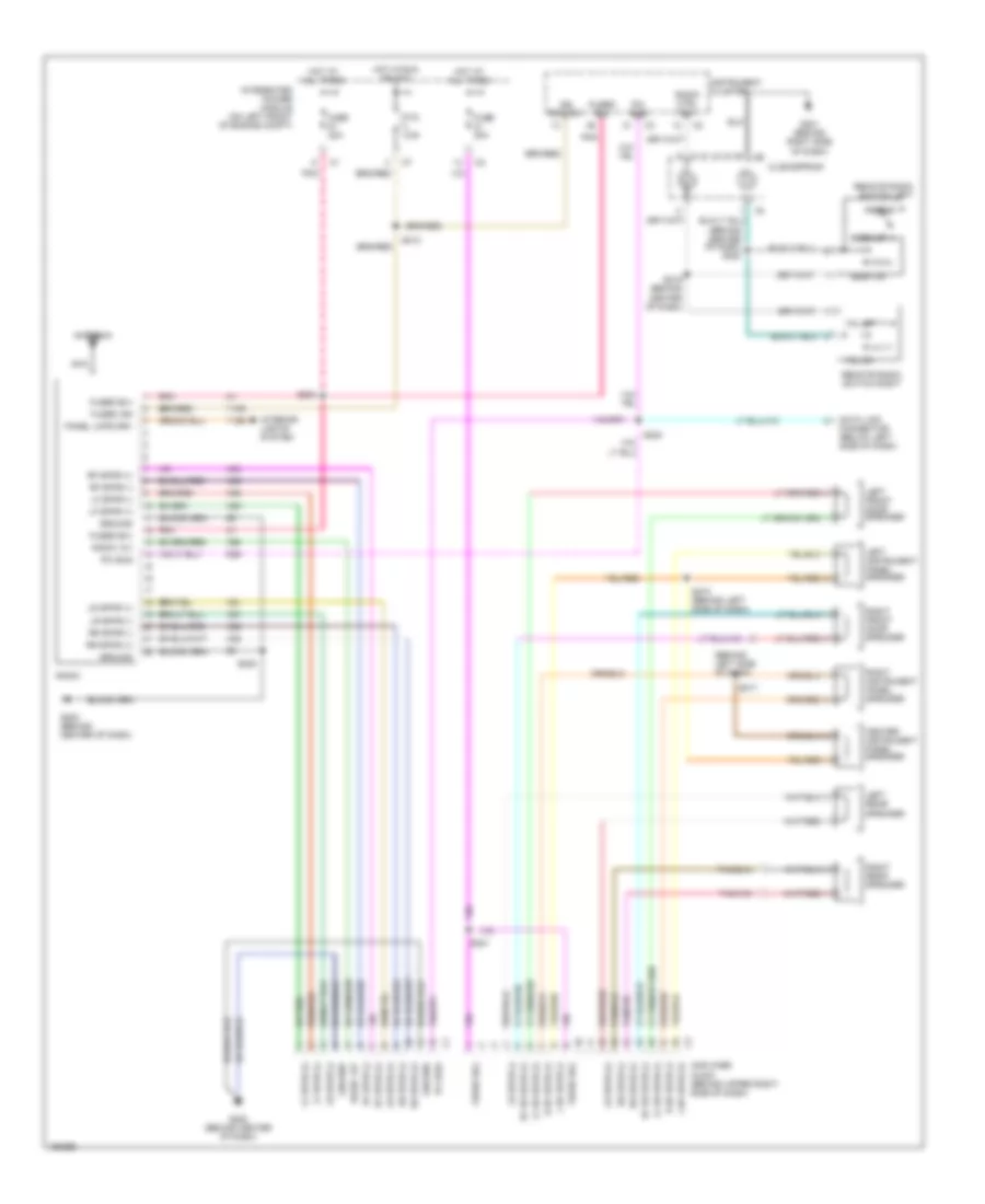
Radio Wiring Diagram, Premium Radio for Dodge Cab & Chassis R2003 3500
List of elements for Radio Wiring Diagram, Premium Radio for Dodge Cab & Chassis R2003 3500:
- (behind center of dash) s220
- (behind left side of dash)
- Amplifier audio (behind upper right side of dash)
- Antenna
- Center instrument panel speaker
- Clockspring
- D25
- Data link connector (below left side of dash)
- Fuse 20a
- Fused b(+)
- Fused ign
- G201 (behind right side of dash)
- G202 (behind center of dash)
- Ground
- Hot at all times
- Hot in run or acc
- Ign switch
- Instrument cluster
- Integrated power module (on left front of engine compt)
- Interior lights system
- L i/p spkr (+)
- L i/p spkr (-)
- Left front door speaker
- Left instrument panel speaker
- Left rear speaker
- Lf dr spkr (+)
- Lf dr spkr (-)
- Lf spkr (+)
- Lf spkr (-)
- Lr spkr (+)
- Lr spkr (-)
- Nca
- Panel lmps drv
- Pci bus
- Pnk
- Preset
- Ptc 4.5a
- R i/p spkr (+)
- R i/p spkr (-)
- Radio
- Radio 12v
- Radio ctrl mux
- Remote radio switch left
- Remote radio switch right
- Rf dr spkr (+)
- Rf dr spkr (-)
- Rf spkr (+)
- Rf spkr (-)
- Right front door speaker
- Right instrument panel speaker
- Right rear speaker
- Rr spkr (+)
- Rr spkr (-)
- S204
- S208
- S212
- S217
- S218 (behind left side of dash)
- S219 (behind center of dash)
- S221
- S230
- Seek dn
- Seek up
- Vol dn
- Vol up
- X51
- X52
- X53
- X54
- X55
- X56
- X57
- X58
- X60
- Y105
- Y166
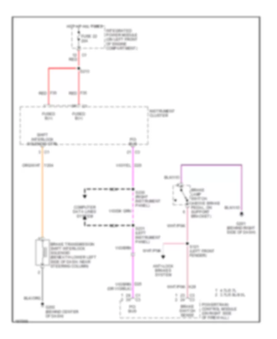
SHIFT INTERLOCK
Shift Interlock Wiring Diagram for Dodge Cab & Chassis R2003 3500
List of elements for Shift Interlock Wiring Diagram for Dodge Cab & Chassis R2003 3500:
- 4.7l/5.7l 3.7l/5.9l/8.0l
- Anti-lock brakes system
- Brake lamp switch (above brake pedal, on support bracket)
- Brake switch sense
- Brake transmission shift interlock solenoid (beneath lower left side of dash, near steering column)
- C1 c3
- C3 c3
- Computer data lines system
- F35 red
- Fuse 22 20a
- Fused b(+)
- G201 (behind right side of dash)
- G202 (behind center of dash)
- Hot at all times
- Instrument cluster
- Integrated power module (on left front of engine compartment)
- Nca
- Pci bus
- Powertrain control module (on right side of firewall)
- Red
- S121 (left front fender)
- S213
- S230 (right instrument panel)
- S231 (left instrument panel)
- Shift interlock solenoid ctrl
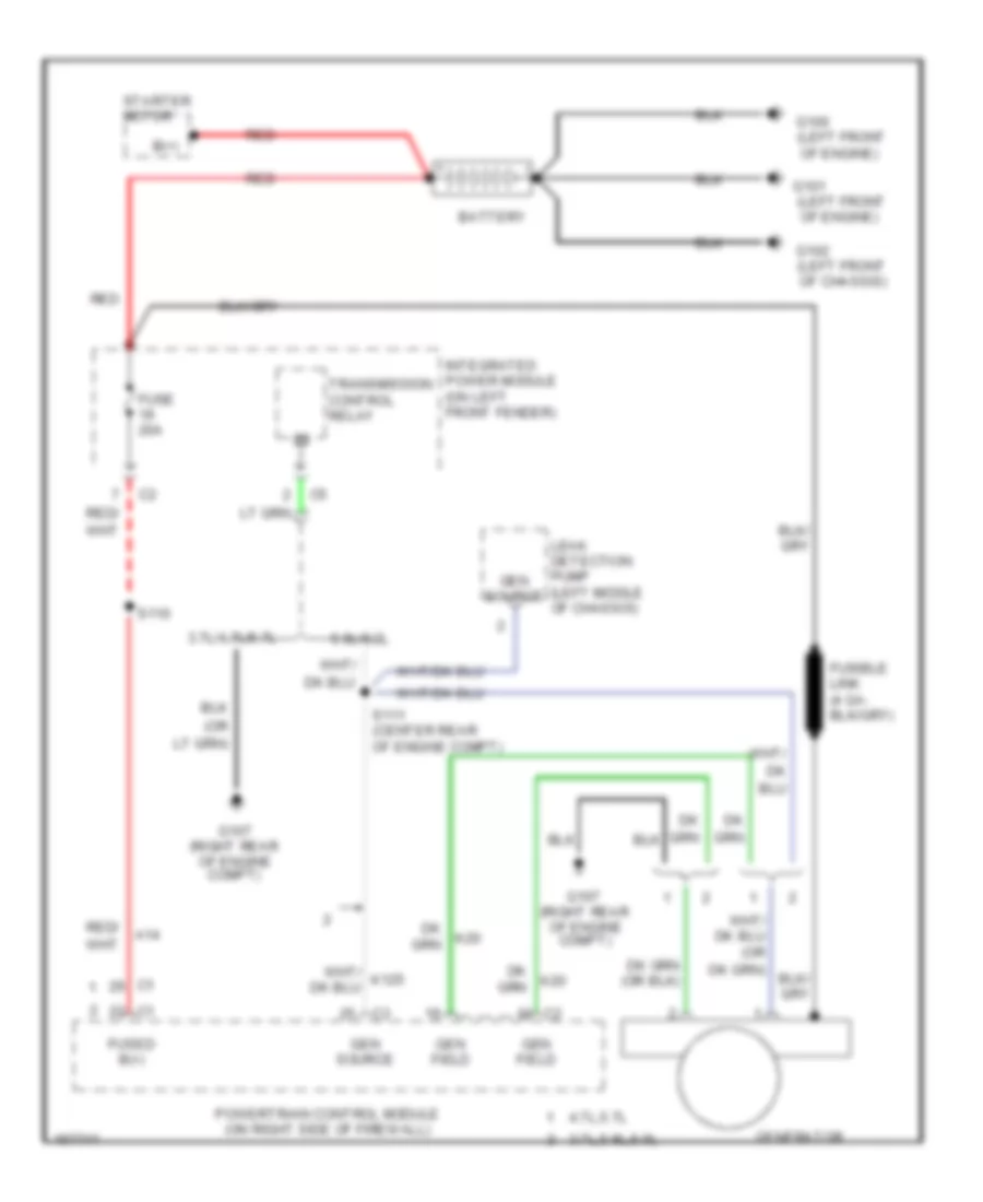
STARTING/CHARGING
5.7L
5.7L, Charging Wiring Diagram for Dodge Cab & Chassis R2003 3500
List of elements for 5.7L, Charging Wiring Diagram for Dodge Cab & Chassis R2003 3500:
- (left front
- (left front of chassis)
- (or
- (right rear of engine compt)
- 3.7l,5.9l,8.0l
- 3.7l/4.7l/5.7l
- 4.7l,5.7l
- 5.9l/8.0l
- A14
- B(+)
- Battery
- Fuse 20a
- Fused b(+)
- G100
- G101
- G102
- G107
- Gen field
- Gen source
- Generator
- Integrated power module (on left front fender)
- Leak detection pump (left middle of chassis)
- Of engine)
- Powertrain control module (on right side of firewall)
- Red
- Red/
- S110
- S111 (center rear of engine compt)
- Starter motor
- Transmission control relay
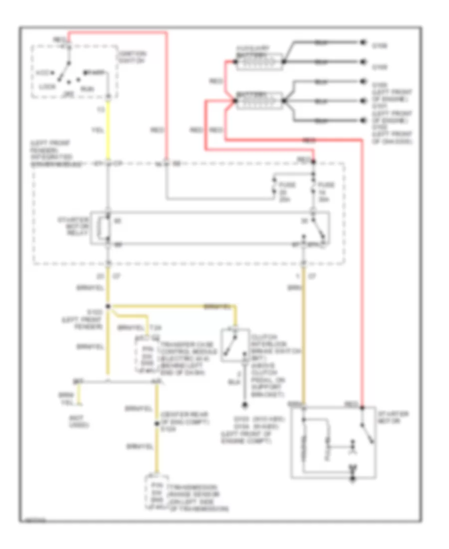
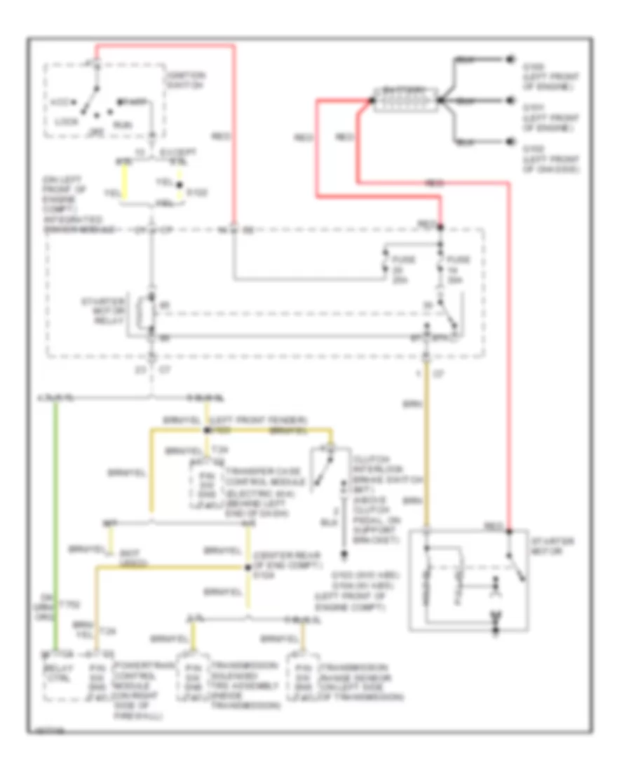
5.7L, Starting Wiring Diagram for Dodge Cab & Chassis R2003 3500
List of elements for 5.7L, Starting Wiring Diagram for Dodge Cab & Chassis R2003 3500:
- (center rear of eng compt) s124
- (electric 4x4) (behind left end of dash)
- (left front of engine compt)
- (not used)
- (on left front of engine compt) integrated power module
- (w/o abs) (w/ abs)
- 3.7l
- 4.7l/5.7l
- 5.9l/8.0l
- 8.0l
- 87a
- A/t
- Acc
- Battery
- Clutch interlock brake switch (m/t) (above clutch pedal, on support bracket)
- Except 8.0l
- Fuse 25a
- Fuse 30a
- G100 (left front of engine)
- G101 (left front of engine)
- G102 (left front of chassis)
- G103 g104
- Hold-in
- Ignition switch
- Lock
- M/t
- Off
- P/n sw sns (t41)
- Powertrain control module (on right side of firewall)
- Pull-in
- Red
- Relay ctrl
- Run
- S122
- Start
- Starter motor
- Starter motor relay
- Transfer case control module
- Transmission range sensor (on left side of transmission)
- Transmission solenoid/ trs assembly (inside transmission)
5.9L DIESEL
5.9L Diesel, Charging Wiring Diagram for Dodge Cab & Chassis R2003 3500
List of elements for 5.9L Diesel, Charging Wiring Diagram for Dodge Cab & Chassis R2003 3500:
- A14
- Auxiliary battery
- B(+)
- Battery
- Engine control module (lower left side of engine block)
- Fuse 20a
- Fused b(+)
- G100 (left front of engine)
- G101 (left front of engine)
- G102 (left front of chassis)
- G108
- G109
- G120
- Gen field ctrl
- Generator
- Integrated power module (on left front of engine compartment)
- Powertrain control module (on right side of firewall)
- Red
- Red/
- S110
- S165
- S166
- S176
- Starter motor
5.9L Diesel, Starting Wiring Diagram for Dodge Cab & Chassis R2003 3500
List of elements for 5.9L Diesel, Starting Wiring Diagram for Dodge Cab & Chassis R2003 3500:
- (center rear of eng compt) s124
- (left front fender) integrated power module
- (left front of engine compt)
- (not used)
- (w/o abs) (w/abs)
- 87a
- A/t
- Acc
- Auxiliary battery
- Battery
- Clutch interlock brake switch (m/t) (above clutch pedal, on support bracket)
- Fuse 25a
- Fuse 30a
- G100 (left front of engine) g101 (left front of engine) g102 (left front of chassis)
- G103
- G104
- G108
- G109
- Hold-in
- Ignition switch
- Lock
- M/t
- Off
- P/n sw sns (t41)
- Pull-in
- Red
- Run
- S123 (left front fender)
- Start
- Starter motor
- Starter motor relay
- Transfer case control module (electric 4x4) (behind left end of dash)
- Transmission range sensor (on left side of transmission)
8.0L
8.0L, Charging Wiring Diagram for Dodge Cab & Chassis R2003 3500
List of elements for 8.0L, Charging Wiring Diagram for Dodge Cab & Chassis R2003 3500:
- (left front
- (left front of chassis)
- (or
- (right rear of engine compt)
- 3.7l,5.9l,8.0l
- 3.7l/4.7l/5.7l
- 4.7l,5.7l
- 5.9l/8.0l
- A14
- B(+)
- Battery
- Fuse 20a
- Fused b(+)
- G100
- G101
- G102
- G107
- Gen field
- Gen source
- Generator
- Integrated power module (on left front fender)
- Leak detection pump (left middle of chassis)
- Of engine)
- Powertrain control module (on right side of firewall)
- Red
- Red/
- S110
- S111 (center rear of engine compt)
- Starter motor
- Transmission control relay
8.0L, Starting Wiring Diagram for Dodge Cab & Chassis R2003 3500
List of elements for 8.0L, Starting Wiring Diagram for Dodge Cab & Chassis R2003 3500:
- (center rear of eng compt) s124
- (electric 4x4) (behind left end of dash)
- (left front of engine compt)
- (not used)
- (on left front of engine compt) integrated power module
- (w/o abs) (w/ abs)
- 3.7l
- 4.7l/5.7l
- 5.9l/8.0l
- 8.0l
- 87a
- A/t
- Acc
- Battery
- Clutch interlock brake switch (m/t) (above clutch pedal, on support bracket)
- Except 8.0l
- Fuse 25a
- Fuse 30a
- G100 (left front of engine)
- G101 (left front of engine)
- G102 (left front of chassis)
- G103 g104
- Hold-in
- Ignition switch
- Lock
- M/t
- Off
- P/n sw sns (t41)
- Powertrain control module (on right side of firewall)
- Pull-in
- Red
- Relay ctrl
- Run
- S122
- Start
- Starter motor
- Starter motor relay
- Transfer case control module
- Transmission range sensor (on left side of transmission)
- Transmission solenoid/ trs assembly (inside transmission)
SUPPLEMENTAL RESTRAINTS
Supplemental Restraints Wiring Diagram for Dodge Cab & Chassis R2003 3500
List of elements for Supplemental Restraints Wiring Diagram for Dodge Cab & Chassis R2003 3500:
- (at left front body) s335
- (behind right side of dash) g204
- Ab rtn
- Ab sns
- Air bag control module (beneath lower center of dash)
- Clockspring
- Computer data lines system
- D25
- Data link connector (dlc) (partial) (below left side of dash)
- Driver air bag
- F14
- F23
- Fuse 20a
- Fused b(+)
- G204 (behind right side of dash)
- Ground
- Hot in run
- Ign run/start
- Ignition
- Ind drv
- Integrated power module (on left front of engine compt)
- Left curtain air bag
- Left seat belt pretensioner (at base of left "b" pillar, behind trim)
- Left side impact air bag control module (at base of left "b" pillar, behind trim)
- Line
- Line 1
- Line 2
- Line1
- Nca
- Passenger air bag
- Passenger air bag on/off switch
- Pci bus
- R42
- R43
- R44
- R45
- R53
- R54
- R55
- R56
- R74
- R75
- R76
- R77
- Right curtain air bag
- Right seat belt pretensioner (at base of right "b" pillar, behind trim)
- Right side impact air bag control module (at base of right "b" pillar, behind trim)
- S146 (left front fender)
- S222 (behind center of dash)
- S230
- S231
- S305 (at center of body)
- S310 (at center of body)
- Y195
- Z11
- Z29
TRANSMISSION
Transfer Case Wiring Diagram for Dodge Cab & Chassis R2003 3500
List of elements for Transfer Case Wiring Diagram for Dodge Cab & Chassis R2003 3500:
- (above clutch pedal) clutch interlock brake switch
- 2wd high
- 2wd/awd ind
- 2wd/awd lamp
- 4wd high
- 4wd high ind
- 4wd high lamp
- 4wd low
- 4wd low ind
- 4wd low lamp
- A34
- D25
- Data link connector (below left side of dash)
- Fuse 10a
- Fuse 25a
- Fused (b+)
- G203 (center of dash)
- Ground
- Hot at all times
- Hot in run or start
- Hot in start
- Integrated power module (on left front of engine compt)
- Interior lights system
- Lock
- Low
- Mode select
- Mode sensor a
- Mode sensor b
- Mode sensor c
- Mode sensor d
- Mode sensor gnd
- N 4wd
- Neutral ind
- Neutral lamp
- Panel lamp
- Pci bus
- Pnp sens (t41)
- Red
- S123 (left front fender)
- S205
- S231 (left side of dash)
- Shift motor ctrl a
- Shift motor ctrl b
- Starter motor relay
- T24
- Transfer case control module (behind left end of dash)
- Transfer case mode sensor (on top left of transfer case)
- Transfer case selector switch
- Transfer case shift motor (on lower left side of transfer case)
- Y113
- Y114
- Y115
- Y116
- Y117
- Y118
- Y120
- Y121
- Y122
- Y123
- Y124
- Y125
- Y187
- Z114
- Z21
- Z366
5.7L
5.7L, A/T Wiring Diagram (1 of 2) for Dodge Cab & Chassis R2003 3500
List of elements for 5.7L, A/T Wiring Diagram (1 of 2) for Dodge Cab & Chassis R2003 3500:
- 2c press sw
- 2c sol ctrl
- 4c press sw
- 4c sol ctrl
- A41
- A51
- A61
- Acc
- Apps 1 out
- B22
- Back-up lamps circuit, mirrors system
- D15
- D25
- Fuse 15a
- Fuse 40a
- Fused (b+)
- G107 (right rear of engine compt)
- Gnd
- Hot at all times
- Hot in run
- Ign sw in
- Ignition switch
- Input spd sens
- Integrated power module (on left front of engine compt)
- K30
- L/r press sw
- Line press sens
- Lock
- Lr/cc sol ctrl
- Ms sol ctrl
- Od off sw
- Od press sw
- Od sol ctrl
- Off
- Output spd sens
- Pci bus
- Pnk
- Press ctrl sol
- Red
- Rpm sig
- Run
- S125 (center rear of engine compt)
- S126
- S210
- Sci receive
- Sci transmit
- Sensor gnd
- Speed sens gnd
- Start
- T10
- T118
- T119
- T120
- T13
- T14
- T140
- T147
- T159
- T16
- T29
- T38
- T39
- T41
- T42
- T48
- T50
- T52
- T54
- T59
- T60
- Torq mgmt req
- Tp1 1 out
- Trans rly ctrl
- Trans rly out
- Trans temp sens
- Transmission control module (on right rear of engine compt)
- Transmission control relay
- Transmission solenoid/trs assembly (inside transmission)
- Trs t1 sense
- Trs t2 sense
- Trs t3 sense
- Trs t41 sens
- Trs t42 sens
- Ud press sw
- Ud sol ctrl
- Vss sig
- Y207
- Y208
- Y209
- Y210
- Z113
- Z13
5.7L, A/T Wiring Diagram (2 of 2) for Dodge Cab & Chassis R2003 3500
List of elements for 5.7L, A/T Wiring Diagram (2 of 2) for Dodge Cab & Chassis R2003 3500:
- Apps 1 out
- B22
- Controller anti-lock brake (left rear of engine compt) c1
- Data link connector (below left side of dash)
- G107 (right rear of engine compt)
- G201 (right side of dash)
- Grd
- Input speed sensor (on left front of transmission)
- Line pressure sensor (on right rear of transmission)
- Output speed sensor (on left rear of transmission)
- Overdrive switch
- P/n sw sens
- Powertrain control module (on right side of firewall)
- Rpm sig
- S117
- S134 (left rear of engine compt)
- S231 (left side of dash)
- T10
- T24
- Torq sense
- Tps 1 out
- Vss sig
- Y207
- Y208
- Y209
- Y210
5.9L
5.9L, A/T Wiring Diagram for Dodge Cab & Chassis R2003 3500
List of elements for 5.9L, A/T Wiring Diagram for Dodge Cab & Chassis R2003 3500:
- (left rear of engine)
- 3-4 sol ctrl
- 5 volt
- 5 volt sply
- A/c pressure transducer (on left side of a/c compressor)
- Cluster mux
- Exterior lights, mirrors systems
- Fuse 40a
- Gen source
- Generator
- Hot at all times
- Instrument cluster
- Integrated power module (left front of engine compt)
- K125
- K30
- K54
- K88
- Leak detection pump (forward of fuel tank)
- Output speed sensor (left rear of transmission)
- Pnk
- Powertrain control module (right side of firewall)
- Press sens sig
- Press sol ctrl
- Red
- Rly ctrl
- S111 (center rear of eng compt)
- S124 (center rear of eng compt)
- S133
- S144 (on top front of transmission)
- Sens grd
- Spd sens grd
- Spd sens sig
- Startng/charging system
- Sw sens
- T13
- T14
- T24
- T25
- T54
- T60
- Tcc sol ctrl
- Trans temp sig
- Transmission range sensor (left side of transmission)
- Transmission relay
- Transmission solenoid assembly (inside transmission)
- Y128
5.9L DIESEL
5.9L Diesel, A/T Wiring Diagram for Dodge Cab & Chassis R2003 3500
List of elements for 5.9L Diesel, A/T Wiring Diagram for Dodge Cab & Chassis R2003 3500:
- 3-4 sol ctrl
- 5 volt
- 5 volt sply
- Cluster mux
- Exterior lights, mirrors systems
- Fuse 10a
- Fuse 40a
- Hot at all times
- Hot in run or start
- Instrument cluster
- Integrated power module (left front of engine compt)
- K30
- K54
- K88
- Output speed sensor (left rear of transmission)
- Pnk
- Powertrain control module (right side of firewall)
- Press sens sig
- Press sol ctrl
- Red
- Rly ctrl
- S124 (center rear of eng compt)
- Sens grd
- Spd sens grd
- Spd sens sig
- Startng/charging system
- Sw sens
- T13
- T14
- T24
- T25
- T54
- T60
- Tcc sol ctrl
- Trans temp sig
- Transmission range sensor (left side of transmission)
- Transmission relay
- Transmission solenoid assembly (inside transmission)
- Y128
8.0L
8.0L, A/T Wiring Diagram for Dodge Cab & Chassis R2003 3500
List of elements for 8.0L, A/T Wiring Diagram for Dodge Cab & Chassis R2003 3500:
- (left rear of engine)
- 3-4 sol ctrl
- 5 volt
- 5 volt sply
- A/c pressure transducer (on left side of a/c compressor)
- Cluster mux
- Exterior lights, mirrors systems
- Fuse 40a
- Gen source
- Generator
- Hot at all times
- Instrument cluster
- Integrated power module (left front of engine compt)
- K125
- K30
- K54
- K88
- Leak detection pump (forward of fuel tank)
- Output speed sensor (left rear of transmission)
- Pnk
- Powertrain control module (right side of firewall)
- Press sens sig
- Press sol ctrl
- Red
- Rly ctrl
- S111 (center rear of eng compt)
- S124 (center rear of eng compt)
- S133
- S144 (on top front of transmission)
- Sens grd
- Spd sens grd
- Spd sens sig
- Startng/charging system
- Sw sens
- T13
- T14
- T24
- T25
- T54
- T60
- Tcc sol ctrl
- Trans temp sig
- Transmission range sensor (left side of transmission)
- Transmission relay
- Transmission solenoid assembly (inside transmission)
- Y128
WARNING SYSTEMS
Warning Systems Wiring Diagram for Dodge Cab & Chassis R2003 3500
List of elements for Warning Systems Wiring Diagram for Dodge Cab & Chassis R2003 3500:
- (0) off (1) park (2) head
- (base)
- (center of body) s320
- (except base)
- Ajar switch- driver
- Door ajar switch- driver
- Door ajar switch- left rear
- Door ajar switch- passenger
- Door ajar switch- right rear
- Door lock motor/
- Door lock motor/ ajar switch- left rear
- Door lock motor/ ajar switch- passenger
- Door lock motor/ ajar switch- right rear
- Driver dr ajar sw sns
- F35
- Fuse 15a
- Fuse 20a
- Fused b(+)
- Fused ign
- G10
- G201 (behind right side of dash)
- G202 (behind center
- G202 (behind center of dash)
- G26
- G301 (on left front of body)
- G74
- G75
- G76
- G77
- Ground
- Hdlp sw ret
- Hdlp sw sig
- Headlamp switch
- Hot at all times
- Hot in run or acc
- Ignition switch
- Instrument cluster
- Integrated power module (on left front of engine compt)
- Key-in sw
- Key-in switch
- Left rear dr ajar sw sns
- Of dash)
- Passenger dr ajar sw sns
- Ptc 4.5a
- Red
- Right rear dr ajar sw sns
- S212
- S213
- S311
- S312
- S313
- Seat belt switch-driver (integral with driver's seat belt buckle)
- Seat blt sw
- Tan
- Tan (or tan/red)
- Tan/red
- Y105
- Y126
- Y167
- Z106
- Z202
- Z203
WIPER/WASHER
Wiper/Washer Wiring Diagram for Dodge Cab & Chassis R2003 3500
List of elements for Wiper/Washer Wiring Diagram for Dodge Cab & Chassis R2003 3500:
- (left front of engine compartment) g104
- (left instrument panel) s231
- (left rear of engine compartment) g106
- (not used)
- (right front of chassis) g105
- (right instrument panel)
- 0. off 1. intermittent 1 2. intermittent 2 3. intermittent 3 4. intermittent 4 5. intermittent 5 6. low 7. high
- 8.0l/ diesel
- 8.0l/diesel
- 87a
- Ambient temperature sensor (on left underside of hood)
- D25
- Data link connector (below left side of dash)
- Except 8.0l/ diesel
- Front control module
- Fuse 8 30a
- G106 (left rear of engine compartment)
- G29
- Hot at all times
- Instrument cluster
- Integrated power module (on left front of engine compartment)
- Intermittent wiper switch sense
- Low washer fluid sense
- Multi-function switch
- Pci bus
- S101
- S119 (left rear of engine compartment)
- S230
- Sensor ground
- V10
- Wash
- Wash/beam select switch feed
- Washer fluid level switch (on washer fluid reservoir)
- Washer pump motor (on washer fluid reservoir)
- Washer pump motor ctrl
- Wiper high/ low relay
- Wiper high/low relay control
- Wiper motor (on left rear of engine compartment)
- Wiper on/off relay
- Wiper on/off relay control
- Wiper park switch sense
- Wiper/turn/beam select sw sense
- Y108
- Y109
- Y137

 Dansk
Dansk Deutsch
 Ελληνικά
 English
 English
 Español
 Suomi
Suomi Français
 Français
 עברית
עברית Hrvatski
 Magyar
 Italiano
 日本語
日本語 한국어
한국어 Nederlands
 Polski
 Português
 Português
 Română
 Русский
 Slovenčina
 Slovenščina
 Svenska
 Türkçe
 中文 (中国)