AIR CONDITIONING
3.8L
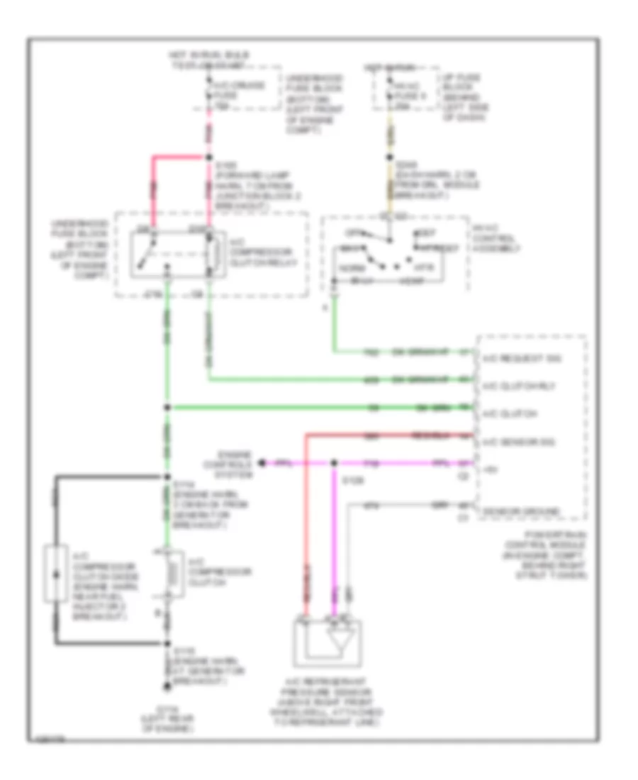
3.8L VIN K, Compressor Wiring Diagram for Pontiac Firebird Trans Am 2001
 https://portal-diagnostov.com/license.html
Automotive Electricians Portal FZCO
Automotive Electricians Portal FZCO
https://portal-diagnostov.com/license.html
https://portal-diagnostov.com/license.html
Automotive Electricians Portal FZCO
Automotive Electricians Portal FZCO
List of elements for 3.8L VIN K, Compressor Wiring Diagram for Pontiac Firebird Trans Am 2001:
- (bottom) (left front of engine compt)
- (engine harn, 8 cm from pcm breakout)
- (forward lamp harn, 14 cm from pcm breakout)
- +5v
- A/c clutch rly
- A/c compressor clutch
- A/c compressor clutch diode (engine harn, near fuel injector 2 breakout)
- A/c compressor clutch relay
- A/c refrigerant pressure sensor (above right front wheelwell, attached to refrigerant line)
- A/c request sig
- A/c sensor sig
- A/c-cruise fuse 15a
- At generator breakout)
- Bi-lv
- C10
- D10
- Def
- Engine controls system
- G114 (left rear of engine)
- Hot in run
- Hot in run, bulb test or start
- Htr
- Htr/def
- Hvac control assembly
- Hvac fuse 6 20a
- I/p fuse block (behind left side of dash)
- Max
- Nca
- Norm
- Off
- Pnk
- Powertrain control module (in engine compt, behind right strut tower)
- S111
- S114 (engine harn, 3 cm back from generator breakout)
- S121
- S165 (forward lamp harn, 7 cm from junction block 2 breakout)
- S248 (dash harn, 2 cm from drl module breakout)
- Sensor ground
- Underhood fuse block
- Vent
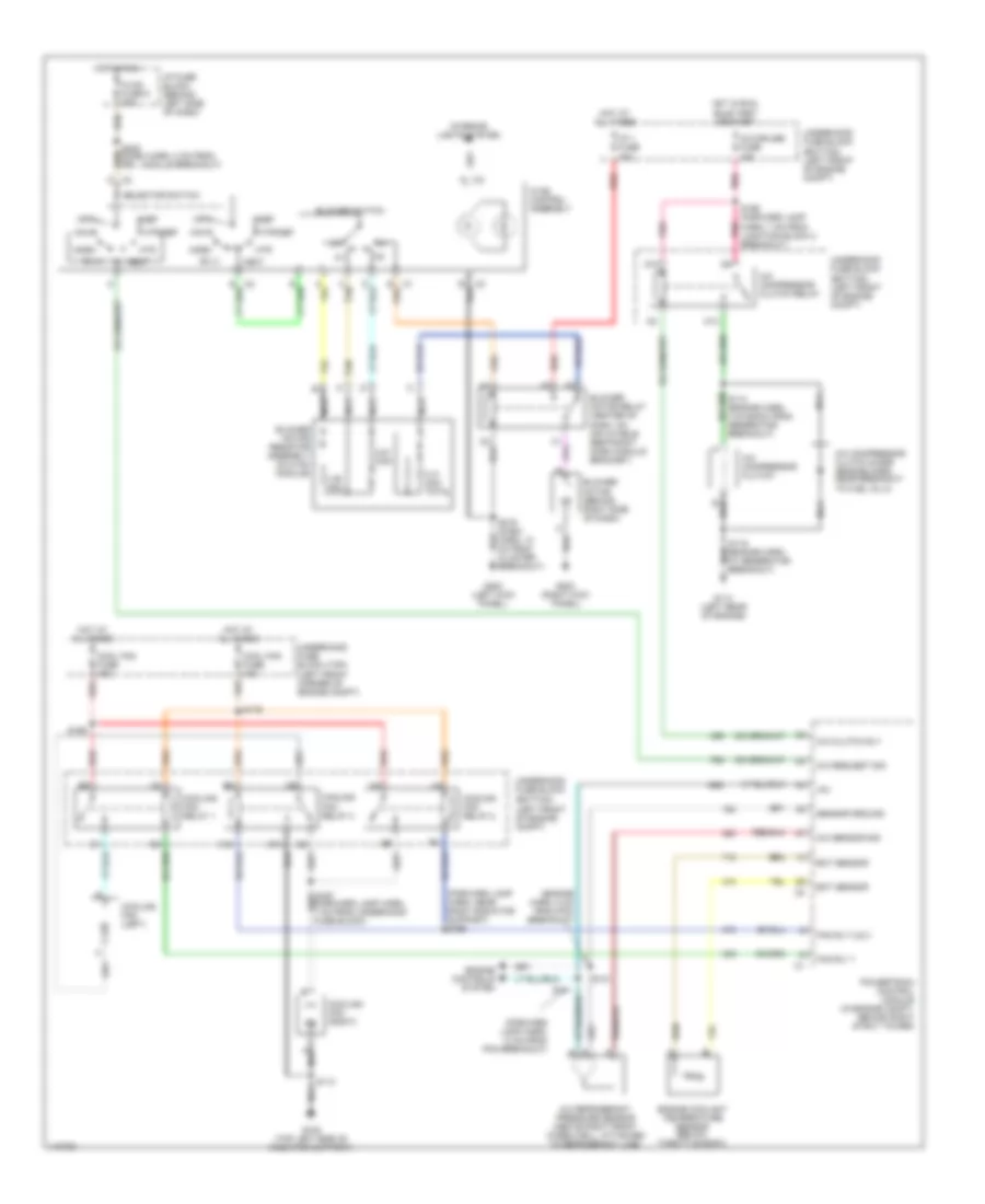
3.8L VIN K, Manual A/C Wiring Diagram for Pontiac Firebird Trans Am 2001
List of elements for 3.8L VIN K, Manual A/C Wiring Diagram for Pontiac Firebird Trans Am 2001:
- (bottom) (left front of engine compt)
- (engine harn, 8 cm from pcm breakout)
- (forward lamp harn, 14 cm from pcm breakout)
- (forward lamp harn, near right radiator support) s166
- +5v
- 0.31 ohm total
- 0.61 ohm
- 1.85 ohm
- A/c clutch rly
- A/c compressor clutch
- A/c compressor clutch diode (engine harn, near breakout to fuel inj 2)
- A/c compressor clutch relay
- A/c refrigerant pressure sensor (above right front wheelwell, attached to refrigerant line)
- A/c request sig
- A/c sensor sig
- A/c-cruise fuse 15a
- B10
- Bi-lv
- Blower motor (behind right side of dash)
- Blower motor relay (center of dash, on inflatable restraint dash module bracket)
- Blower motor resistor assembly (in hvac module)
- Blower switch
- C tan
- C10
- Cool fan fuse 10a
- Cool fan fuse 40a
- Cooling fan (left)
- Cooling fan (right)
- Cooling fan relay 1
- Cooling fan relay 2
- Cooling fan relay 3
- D10
- Def
- Ect sensor
- Engine controls system
- Engine coolant temperature sensor (below throttle body)
- Fan rly 1
- Fan rly 2 & 3
- G108 (top left side of radiator support)
- G114 (left rear of engine)
- G200 (left kick panel)
- G203 (right kick panel)
- Hot at all times
- Hot in run
- Hot in run, bulb test or start
- Htr
- Htr/def
- Hvac control assembly
- Hvac fuse 6 20a
- I/p 1 fuse 40a
- I/p fuse block (behind left side of dash)
- Interior lights system
- Max
- Nca
- Norm
- Off
- Pnk
- Powertrain control module (in engine compt, behind right strut tower)
- Red
- S111
- S113
- S115 (engine harn, at generator breakout)
- S121
- S165 (forward lamp harn, 7 cm from junction block 2 breakout)
- S169
- S179
- S216 (dash harn, 10 cm from cluster breakout)
- S248 (dash harn, 2 cm from drl module breakout)
- Selector switch
- Sensor ground
- Tan
- Underhood fuse block
- Underhood fuse block (top) (left front corner of engine compt)
- Vent
5.7L
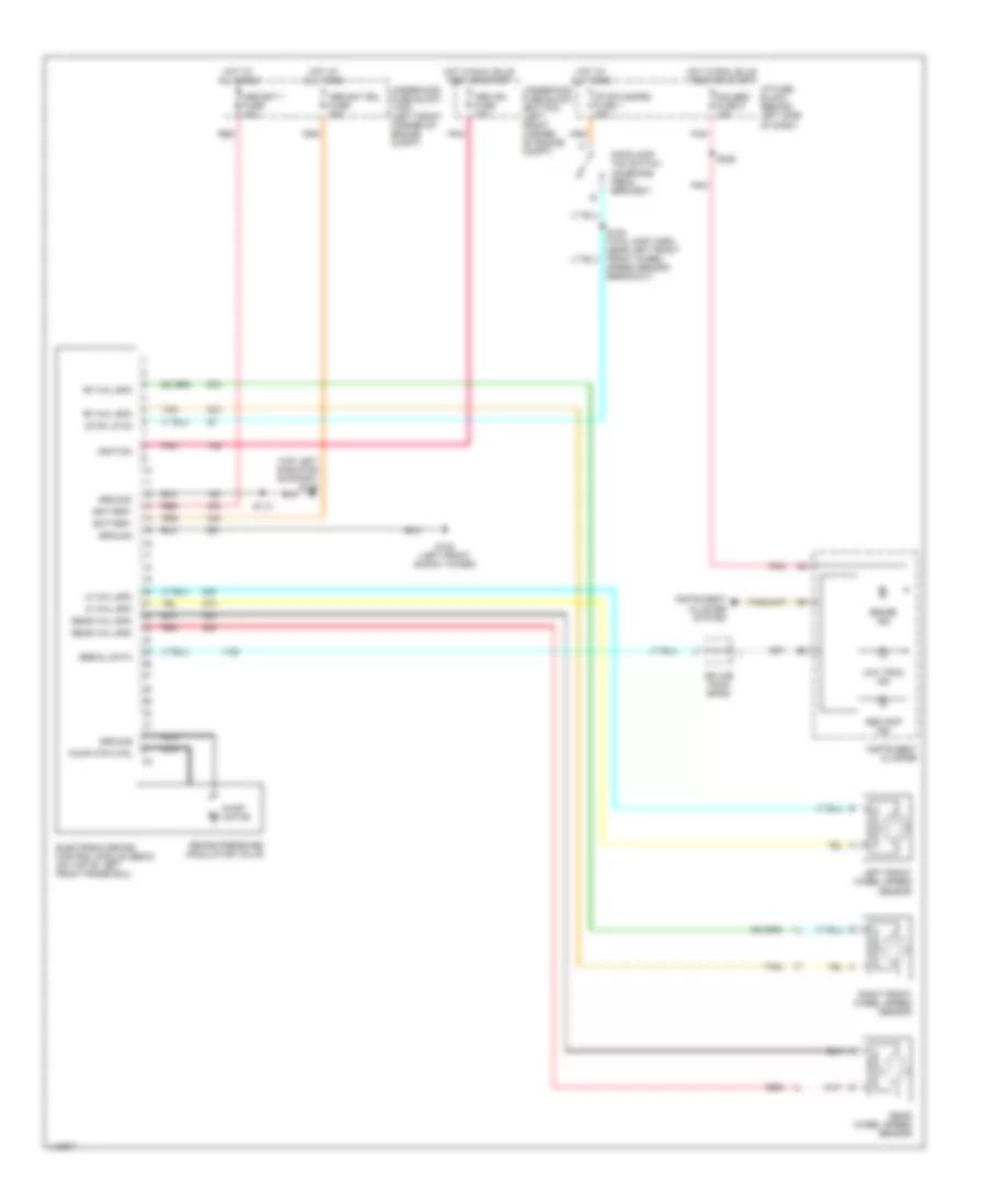
5.7L VIN G, Compressor Wiring Diagram for Pontiac Firebird Trans Am 2001
List of elements for 5.7L VIN G, Compressor Wiring Diagram for Pontiac Firebird Trans Am 2001:
- (bottom) (left front of engine compt)
- +5v
- A/c clutch
- A/c clutch rly
- A/c compressor clutch
- A/c compressor clutch diode (engine harn, near fuel injector 2 breakout)
- A/c compressor clutch relay
- A/c refrigerant pressure sensor (above right front wheelwell, attached to refrigerant line)
- A/c request sig
- A/c sensor sig
- A/c-cruise fuse 15a
- At generator breakout)
- Bi-lv
- C10
- D10
- Def
- Engine controls system
- G114 (left rear of engine)
- Hot in run
- Hot in run, bulb test or start
- Htr
- Htr/def
- Hvac control assembly
- Hvac fuse 6 20a
- I/p fuse block (behind left side of dash)
- Max
- Nca
- Norm
- Off
- Pnk
- Powertrain control module (in engine compt, behind right strut tower)
- S114 (engine harn, 3 cm back from generator breakout)
- S128
- S165 (forward lamp harn, 7 cm from junction block 2 breakout)
- S248 (dash harn, 2 cm from drl module breakout)
- Sensor ground
- Underhood fuse block
- Vent
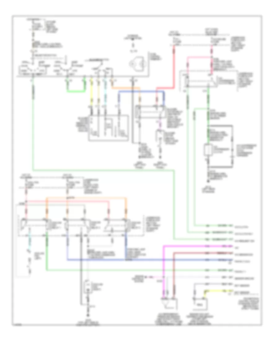
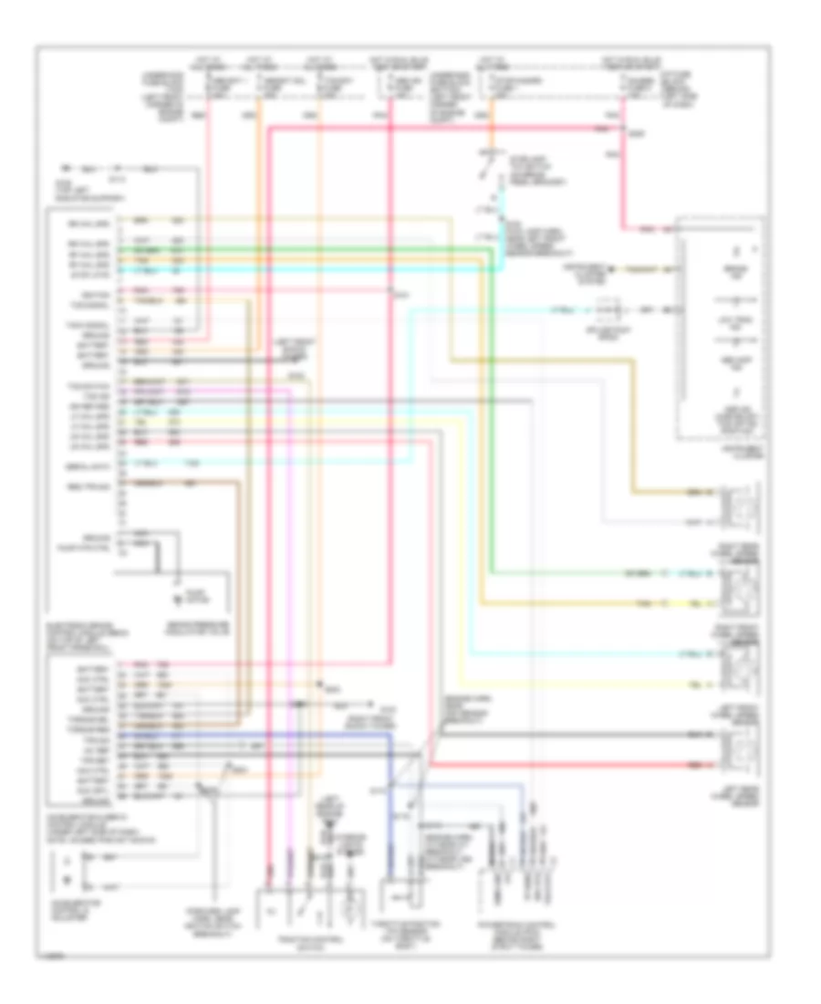
5.7L VIN G, Manual A/C Wiring Diagram for Pontiac Firebird Trans Am 2001
List of elements for 5.7L VIN G, Manual A/C Wiring Diagram for Pontiac Firebird Trans Am 2001:
- (bottom) (left front of engine compt)
- (forward lamp harn, near right radiator support) s166
- +5v
- 0.31 ohm total
- 0.61 ohm
- 1.85 ohm
- A/c clutch
- A/c clutch rly
- A/c compressor clutch
- A/c compressor clutch diode (in a/c compressor harness)
- A/c compressor clutch relay
- A/c refrigerant pressure sensor (above right front wheelwell, attached to refrigerant line)
- A/c request sig
- A/c sensor sig
- A/c-cruise fuse 15a
- B10
- Bi-lv
- Blower motor (behind right side of dash)
- Blower motor relay (center of dash, on inflatable restraint dash module bracket)
- Blower motor resistor assembly (in hvac module)
- Blower switch
- C tan
- C10
- Cool fan fuse 10a
- Cool fan fuse 40a
- Cooling fan (left)
- Cooling fan (right)
- Cooling fan relay 1
- Cooling fan relay 2
- Cooling fan relay 3
- D10
- Def
- Ect sensor
- Engine controls system
- Engine coolant temperature sensor (lower left side of engine, above generator)
- Fan rly 1
- Fan rly 2 & 3
- G108 (top left side of radiator support)
- G114 (left rear of engine)
- G200 (left kick panel)
- G203 (right kick panel)
- Hot at all times
- Hot in run
- Hot in run, bulb test or start
- Htr
- Htr/def
- Hvac control assembly
- Hvac fuse 6 20a
- I/p 1 fuse 40a
- I/p fuse block (behind left side of dash)
- Interior lights system
- Max
- Nca
- Norm
- Off
- Pnk
- Powertrain control module (in engine compt, behind right strut tower)
- Red
- S105 (engine harn, at ac/ press sensor)
- S113
- S115 (engine harn, at generator breakout)
- S128
- S165 (forward lamp harn, 7 cm from junction block 2 breakout)
- S169
- S179
- S216 (dash harn, 10 cm from cluster breakout)
- S248 (dash harn, 2 cm from drl module breakout)
- Selector switch
- Sensor ground
- Tan
- Underhood fuse block
- Underhood fuse block (top) (left front corner of engine compt)
- Vent
ANTI-LOCK BRAKES
3.8L
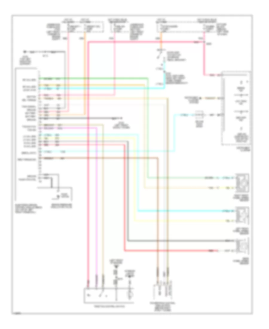
3.8L VIN K, Anti-lock Brake Wiring Diagrams, with Traction Control for Pontiac Firebird Trans Am 2001
List of elements for 3.8L VIN K, Anti-lock Brake Wiring Diagrams, with Traction Control for Pontiac Firebird Trans Am 2001:
- (left front of engine) g110
- Abs bat 1 fuse 40a
- Abs bat sol fuse 25a
- Abs ign fuse 10a
- Abs inop ind
- Asr ind (chevrolet) tcs off ind (pontiac)
- Battery
- Brake ind
- Brake pressure modulator valve
- C1 req tor
- C2 del tor
- Del torque
- Electronic brake control module (ebcm) (on top of left front frame rail)
- G102 (left front shock tower)
- G108 (top left radiator support)
- Gauges fuse 9 10a
- Ground
- Hot at all times
- Hot in run, bulb test or start
- I/p fuse block (behind left side of dash)
- Ignition
- Instrument cluster
- Instrument cluster system
- Interior lights system
- Left front wheel speed sensor
- Lf whl spd
- Low trac ind
- Nca
- Pnk
- Pnk b
- Powertrain control module (pcm) (behind right strut tower)
- Pump motor
- Pump mtr ctrl
- R whl spd
- Rear wheel speed sensor
- Red
- Req torque sig
- Rf whl spd
- Right front wheel speed sensor
- S113
- S206
- S215
- Serial data
- Splice pack sp200
- Stop lp fd
- Stop/hazard fuse 1 20a
- Stoplamp/ tcc switch (on brake pedal bracket)
- Tach out
- Tach signal
- Tan
- Tcs ind
- Tcs switch
- Traction control switch
- Underhood fuse block (bottom) (left front corner of engine compt)
- Underhood fuse block (top) (left front corner of engine compt)
3.8L VIN K, Anti-lock Brake Wiring Diagrams, without Traction Control for Pontiac Firebird Trans Am 2001
List of elements for 3.8L VIN K, Anti-lock Brake Wiring Diagrams, without Traction Control for Pontiac Firebird Trans Am 2001:
- (top left radiator support) g108
- Abs bat 1 fuse 40a
- Abs bat sol fuse 25a
- Abs ign fuse 10a
- Abs inop ind
- Battery
- Brake ind
- Brake pressure modulator valve
- Electronic brake control module (ebcm) (on top of left front frame rail)
- G102 (left front shock tower)
- Gauges fuse 9 10a
- Ground
- Hot at all times
- Hot in run, bulb test or start
- I/p fuse block (behind left side of dash)
- Ignition
- Instrument cluster
- Instrument cluster system
- Left front wheel speed sensor
- Lf whl spd
- Low trac ind
- Nca
- Pnk
- Pump motor
- Pump mtr ctrl
- Rear wheel speed sensor
- Rear whl spd
- Red
- Rf whl spd
- Right front wheel speed sensor
- S113
- S154 (fwd lamp harn, near left front front wheel speed sensor breakout)
- S206
- Serial data
- Splice pack sp200
- Stop lp fd
- Stop/hazard fuse 1 20a
- Stoplamp/ tcc switch (on brake pedal bracket)
- Tan
- Underhood fuse block (bottom) (left front corner of engine compt)
- Underhood fuse block (top) (left front corner of engine compt)
5.7L
5.7L VIN G, Anti-lock Brake Wiring Diagrams, with Traction Control for Pontiac Firebird Trans Am 2001
List of elements for 5.7L VIN G, Anti-lock Brake Wiring Diagrams, with Traction Control for Pontiac Firebird Trans Am 2001:
- (engine harn, a/t-near a/t breakout, m/t-near vss breakout)
- (engine harn, near map sensor breakout)
- (forward lamp harn, near ignition switch breakout)
- (left front shock tower)
- (left rear of engine) g114
- (right front shock tower)
- +5v
- +5v ref
- Abs bat 1 fuse 40a
- Abs bat sol fuse 25a
- Abs ign fuse 10a
- Abs inop ind
- Acc crtl
- Acc ctrl
- Accelerator & servo control module (under left side of dash)
- Accelerator control & adjuster
- Asr ind (chevrolet) tcs off ind (pontiac)
- Battery
- Brake ind
- Brake pressure modulator valve
- Electronic brake control module (ebcm) (on top of left front frame rail)
- G102
- G103
- G108 (top left radiator support)
- Gauges fuse 9 10a
- Ground
- Hot at all times
- Hot in run, bulb test or start
- I/p fuse block (behind left side of dash)
- Ign retard
- Ignition
- Instrument cluster
- Instrument cluster system
- Interior lights system
- Left front wheel speed sensor
- Left rear wheel speed sensor
- Lf whl spd
- Low trac ind
- Lr whl spd
- Nca
- Note: unused pins not shown
- Pnk
- Pnk b
- Powertrain control module (pcm) (behind right strut tower)
- Pump motor
- Pump mtr ctrl
- Red
- Req tps sig
- Rf whl spd
- Right front wheel speed sensor
- Right rear wheel speed sensor
- Rr whl spd
- S113
- S116
- S118
- S119
- S154 (fwd lamp harn, near left front wheel speed sensor breakout)
- S181
- S203
- S204
- S205
- S206
- S209
- S215
- Sens gnd
- Serial data
- Spk rtd
- Splice pack sp200
- Stop lp fd
- Stop/hazard fuse 1 20a
- Stoplamp/ tcc switch (on brake pedal bracket)
- Tach out
- Tach signal
- Tan
- Tcs bat fuse 20a
- Tcs ind
- Tcs signal
- Tcs switch
- Throttle position (tp) sensor (on throttle body)
- Torque del
- Torque req
- Tp sens
- Tps ret
- Tps sig
- Traction control switch
- Underhood fuse block (bottom) (left front corner of engine compt)
- Underhood fuse block (top) (left front corner of engine compt)
5.7L VIN G, Anti-lock Brake Wiring Diagrams, without Traction Control for Pontiac Firebird Trans Am 2001
List of elements for 5.7L VIN G, Anti-lock Brake Wiring Diagrams, without Traction Control for Pontiac Firebird Trans Am 2001:
- (top left radiator support) g108
- Abs bat 1 fuse 40a
- Abs bat sol fuse 25a
- Abs ign fuse 10a
- Abs inop ind
- Battery
- Brake ind
- Brake pressure modulator valve
- Electronic brake control module (ebcm) (on top of left front frame rail)
- G102 (left front shock tower)
- Gauges fuse 9 10a
- Ground
- Hot at all times
- Hot in run, bulb test or start
- I/p fuse block (behind left side of dash)
- Ignition
- Instrument cluster
- Instrument cluster system
- Left front wheel speed sensor
- Lf whl spd
- Low trac ind
- Nca
- Pnk
- Pump motor
- Pump mtr ctrl
- Rear wheel speed sensor
- Rear whl spd
- Red
- Rf whl spd
- Right front wheel speed sensor
- S113
- S154 (fwd lamp harn, near left front front wheel speed sensor breakout)
- S206
- Serial data
- Splice pack sp200
- Stop lp fd
- Stop/hazard fuse 1 20a
- Stoplamp/ tcc switch (on brake pedal bracket)
- Tan
- Underhood fuse block (bottom) (left front corner of engine compt)
- Underhood fuse block (top) (left front corner of engine compt)
ANTI-THEFT
Anti-theft Wiring Diagram for Pontiac Firebird Trans Am 2001
List of elements for Anti-theft Wiring Diagram for Pontiac Firebird Trans Am 2001:
- (3.8l)
- (5.7l)
- (i/p harn, near rear compartment lid release relay) s211
- (left kick panel)
- (ua6)
- A10
- Accy
- Body control module (under right side of dash, near blower motor)
- Bulb test
- C11
- C12
- C16
- C2 e
- Courtesy fuse 8 20a
- D11
- D12
- D13
- D14
- Driver door lock
- Driver dr open
- Front passenger door lock
- Fuel enable
- G200
- G200 (left kick panel)
- G407 (on hatch release bracket)
- Gages fuse 9 10a
- Grd
- Hatch ajar in
- Horn rly ctrl
- Horns system
- Hot at all times
- Hot in run, bulb test or start
- I/p fuse block
- Ign
- Ignition key
- Ignition key lock cylinder
- Ignition switch
- Ind ctrl
- Instrument cluster system
- Instrument panel cluster
- Lock
- Nca
- Off
- Pass dr open
- Pnk
- Powertrain control module (behind right strut tower)
- Pwr accy fuse 7 15a
- Rear compartment lid ajar indication switch
- Red
- Relay ctrl
- Resistor fd
- Resistor pellet
- Resistor ret
- Run
- S206
- S217
- S220
- S254
- S470
- Sec led ctrl
- Security indicator
- Security indicator led (top center of dash)
- Shock
- Shock in
- Start
- Start rly ctrl
- Starting system
- System lights exterior
- Tamper
- Theft deterrent relay (on inflatable restraint dash module bracket)
- Theft deterrent shock sensor (ua6) (in right rear quarter panel)
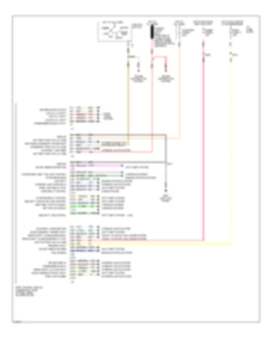
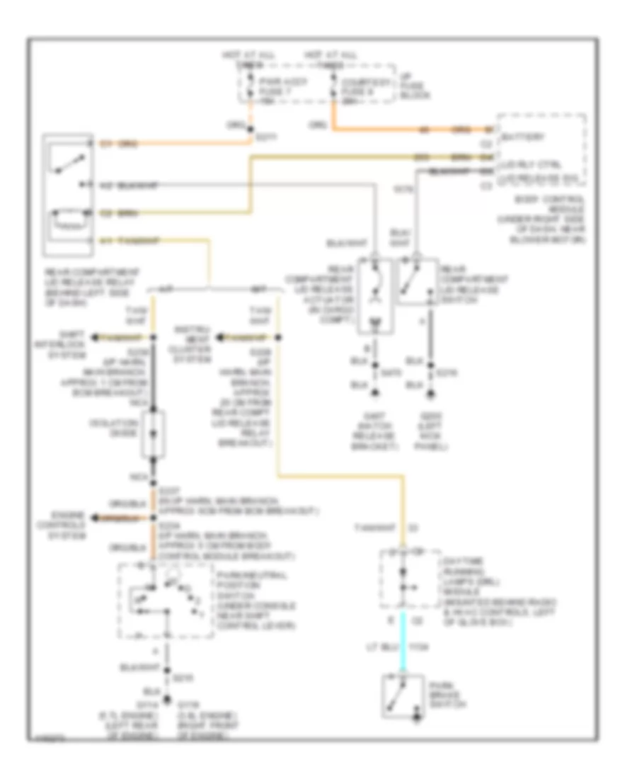
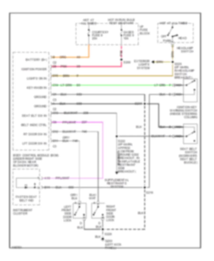
BODY COMPUTER
Body Computer Wiring Diagrams for Pontiac Firebird Trans Am 2001
List of elements for Body Computer Wiring Diagrams for Pontiac Firebird Trans Am 2001:
- (ua6)
- (v6 vin k)
- Accessory positive voltage
- Accy
- Anti-theft system
- Battery positive voltage
- Body control module (under right side of dash, near blower motor)
- Bulb test
- C10
- C11
- C12
- C13
- C14
- C15
- C16
- Courtesy fuse 8 20a
- Courtesy lamp feed
- Courtesy lamps return
- D10
- D11
- D12
- D13
- D14
- D15
- D16
- Door locks system
- Driver open in
- Driver's door unlock
- Engine controls system
- Exterior lights system
- Fasten seat belt ind light control
- Fuel enable
- G200 (left kick panel)
- Gages fuse 9 10a
- Ground
- Horn relay control
- Horns system
- Hot at all times
- Hot in acc, run or w/ rap energized
- Hot in run, bulb test or start
- I/p fuse block
- Ign key resistor feed
- Ign key resistor return
- Ignition positive voltage
- Ignition switch
- Interior lamp command in
- Interior lights system
- Key ignition signal
- Lock
- Lock all input
- Lock all output
- Off
- Park lamp relay ctrl
- Park lights feed
- Passenger door in
- Passenger's door output
- Pnk
- Power distribution system
- Power distribution system (rap relay)
- Program input
- Radio fuse 17 15a
- Rear compt lid ajar input
- Rear compt lid release relay ctrl
- Rear compt lid release signal
- Red
- Retained accessory power (rap)
- Run
- S206
- S217
- S218
- S254
- Seat belt switch signal
- Security indicator lamp control
- Security led control
- Shock sensor "shock" input
- Shock sensor "tamper" input
- Start
- Starter enable
- Starter relay control
- Tan
- Trunk, tailgate, fuel doors system
- Unlock all input
- Vss input
- Warning systems
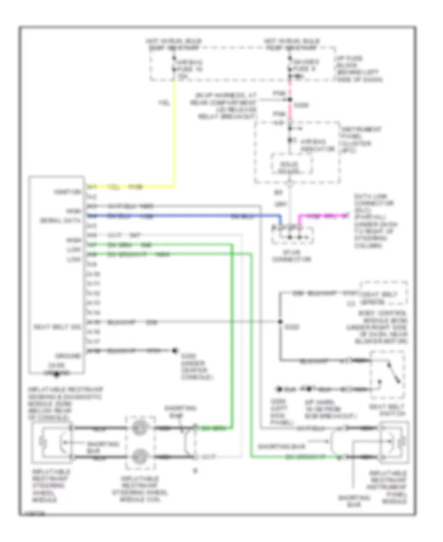
COMPUTER DATA LINES
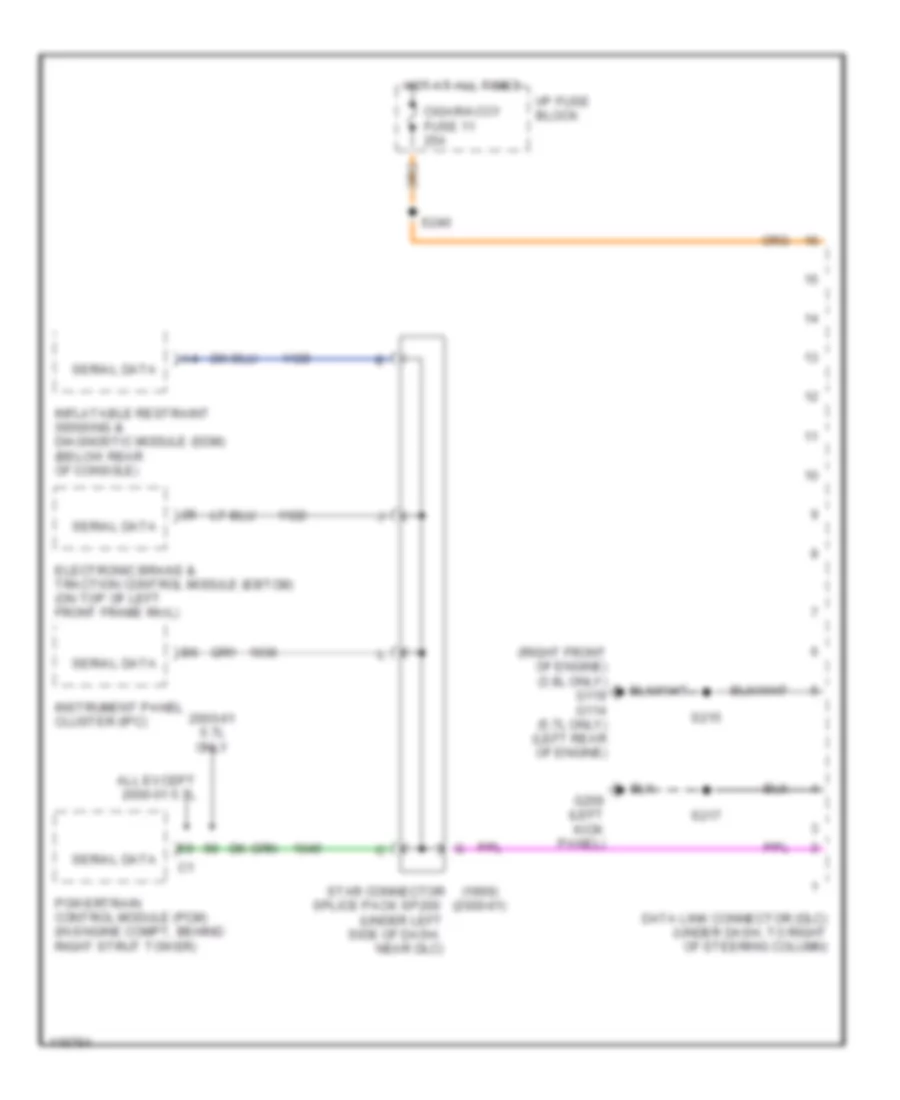
Computer Data Lines for Pontiac Firebird Trans Am 2001
List of elements for Computer Data Lines for Pontiac Firebird Trans Am 2001:
- (1999)
- (2000-01)
- (right front of engine) (3.8l only) g119 g114 (5.7l only) (left rear of engine)
- (under left
- 2000-01 5.7l only
- All except 2000-01 5.7l
- Cigar/accy fuse 11 25a
- Data link connector (dlc) (under dash, to right of steering column)
- Electronic brake & traction control module (ebtcm) (on top of left front frame rail)
- G200 (left kick panel)
- Hot at all times
- I/p fuse block
- Inflatable restraint sensing & diagnostic module (sdm) (below rear of console)
- Instrument panel cluster (ipc)
- Near dlc)
- Powertrain control module (pcm) (in engine compt, behind right strut tower)
- S215
- S217
- S240
- Serial data
- Side of dash,
- Splice pack sp200
- Star connector
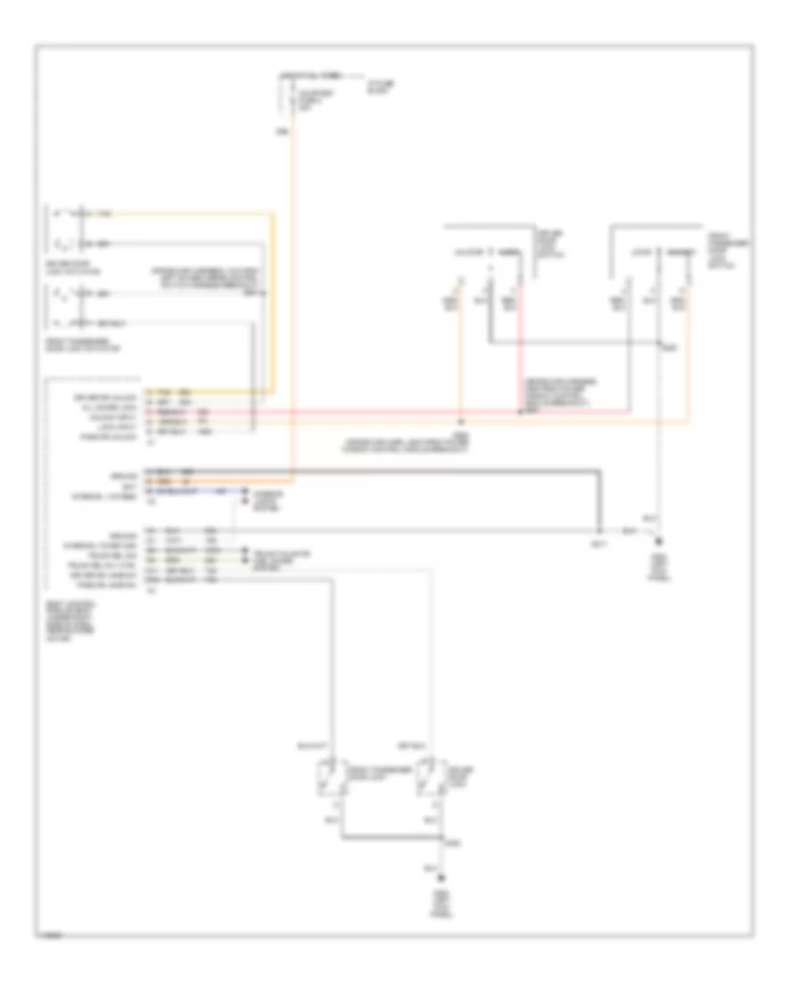
COOLING FAN
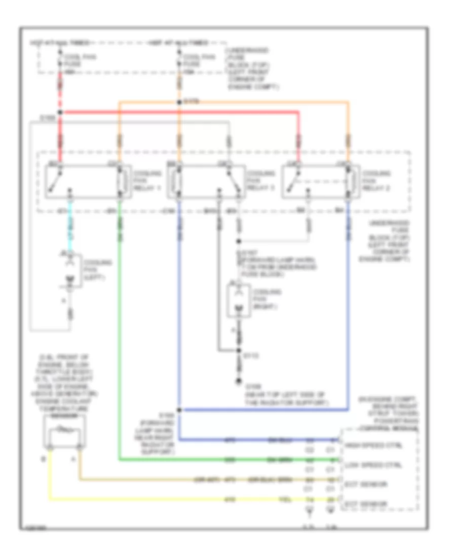
Cooling Fan Wiring Diagram for Pontiac Firebird Trans Am 2001
List of elements for Cooling Fan Wiring Diagram for Pontiac Firebird Trans Am 2001:
- (3.8l: front of engine, below throttle body) (5.7l: lower left side of engine, above generator) engine coolant temperature sensor
- (in engine compt, behind right strut tower) powertrain control module
- (near top left side of
- (or 407)
- 3.8l
- 5.7l
- B10
- C10
- Cool fan fuse 10a
- Cool fan fuse 40a
- Cooling fan (left)
- Cooling fan (right)
- Cooling fan relay 1
- Cooling fan relay 2
- Cooling fan relay 3
- Ect sensor
- G108
- High speed ctrl
- Hot at all times
- Low speed ctrl
- Red
- S113
- S166 (forward lamp harn, near right radiator support)
- S169
- S179
- The radiator support)
- Underhood fuse block (top) (left front corner of engine compt)
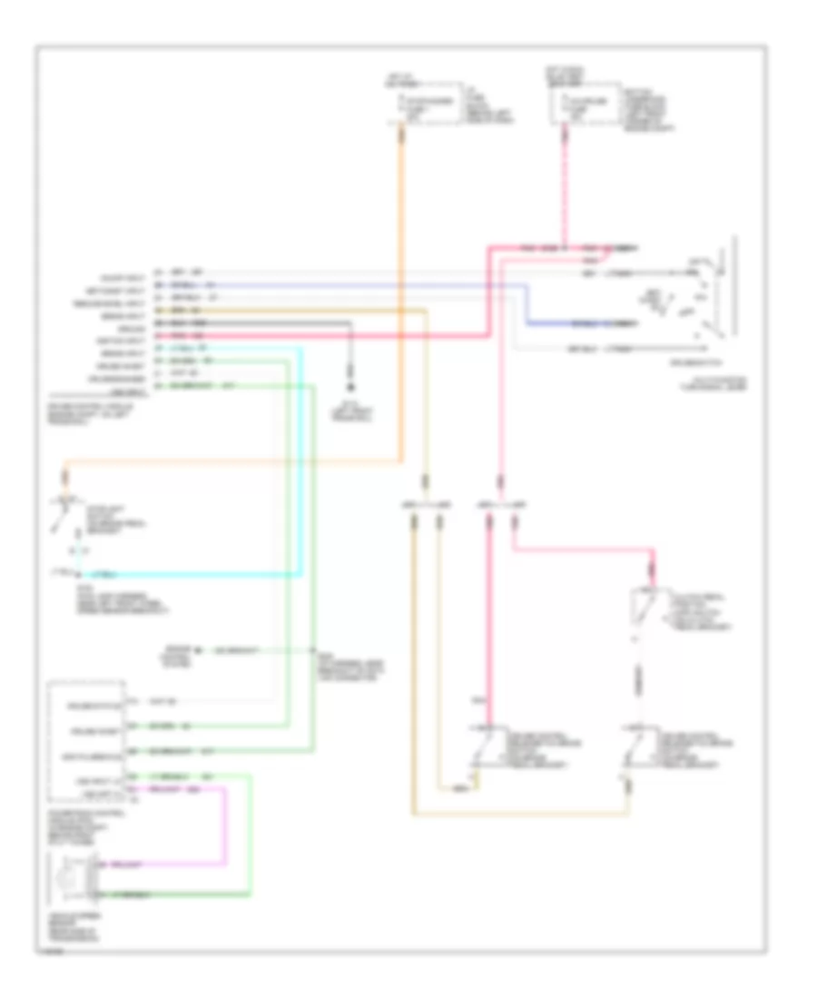
CRUISE CONTROL
3.8L
3.8L VIN K, Cruise Control Wiring Diagram for Pontiac Firebird Trans Am 2001
List of elements for 3.8L VIN K, Cruise Control Wiring Diagram for Pontiac Firebird Trans Am 2001:
- A/c system
- Batt
- Bottom underhood fuse block
- Brk sw sig
- Clutch anticipate
- Clutch pedal position (cpp) switch (on clutch pedal bracket)
- Cruise control release switch (on brake pedal bracket)
- Cruise switch
- Etc fuse 10a
- G110 (left front of engine)
- Hot at all times
- Hot in run, bulb test, or start
- I/p fuse block
- Ign
- Mtr driv hi
- Mtr driv lo
- Multifunction turn signal lever
- Nca
- Off
- Off/on sig
- Pnk
- Powertrain control module (in engine compt, behind right strut tower)
- R/a
- R/a sig
- Release sig
- S101
- S110
- S154 (fwd lamp harn, near left front wheel speed sensor breakout)
- S171
- S215
- Serial data
- Set/coast
- Set/coast sig
- Stop/ hazard fuse 1 20a
- Stoplight switch (on brake pedal bracket)
- Tac ground
- Tan
- Tcs batt fuse 20a
- Throttle actuator control (on throttle body)
- Throttle actuator control (tac) module (on accelerator pedal bracket)
- Top underhood fuse block
- Tp snsr 1
- Tp snsr 1 gnd
- Tp snsr 1 sig
- Tp snsr 2
- Tp snsr 2 gnd
- Tp snsr 2 sig
- Vehicle speed sensor (vss) (on rear side of transmission)
- Vss hiigh
- Vss low
5.7L
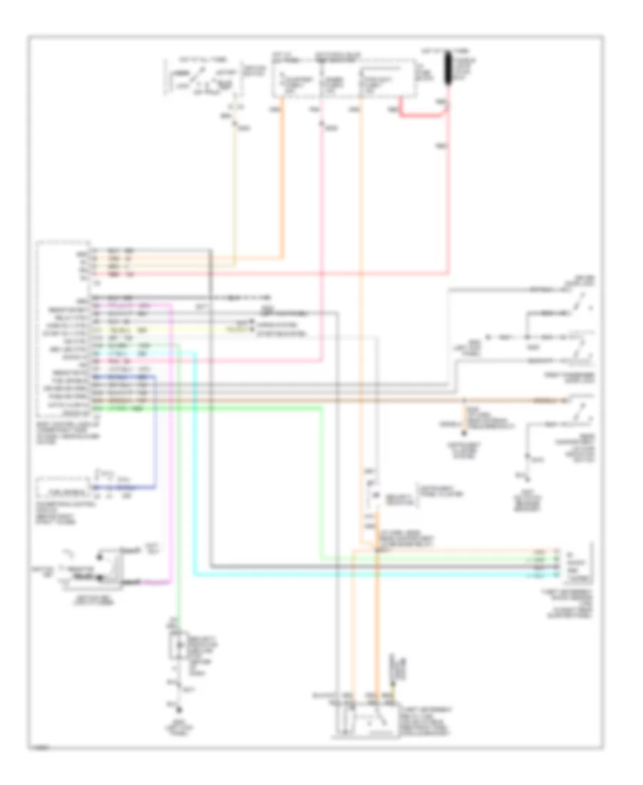
5.7L VIN G, Cruise Control Wiring Diagram for Pontiac Firebird Trans Am 2001
List of elements for 5.7L VIN G, Cruise Control Wiring Diagram for Pontiac Firebird Trans Am 2001:
- 4000 pulses/mile
- A c1
- A/c-cruise fuse 15a
- A/t
- B c1
- Bottom underhood fuse block (left front corner of engine compt)
- Brake input
- Clutch pedal position (cpp) switch (on clutch pedal bracket)
- Cruise control module (engine compt, on left frame rail)
- Cruise control release/tcc brake switch (on brake pedal bracket)
- Cruise engaged
- Cruise inhibit
- Cruise status
- Cruise switch
- Engine control system
- G113 (left front frame rail)
- Ground
- Hot at all times
- Hot in run, bulb test or start
- I/p fuse block (behind left side of dash)
- Ignition input
- M/t
- Multi-function turn signal lever
- Nca
- Off
- On/off input
- Pnk
- Powertrain control module (pcm) (in engine compt, behind right stut tower)
- R/a
- Resume/accel input
- S154 (fwd lamp harness, near left front wheel speed sensor breakout)
- S165
- S242 (i/p harness, near breakout of data link connector)
- Set/ coast sw
- Set/coast input
- Stop/hazard fuse 1 20a
- Stoplight switch (on brake pedal bracket)
- Vehicle speed sensor (rear side of transmission)
- Vss inpt hi
- Vss input
- Vss input lo
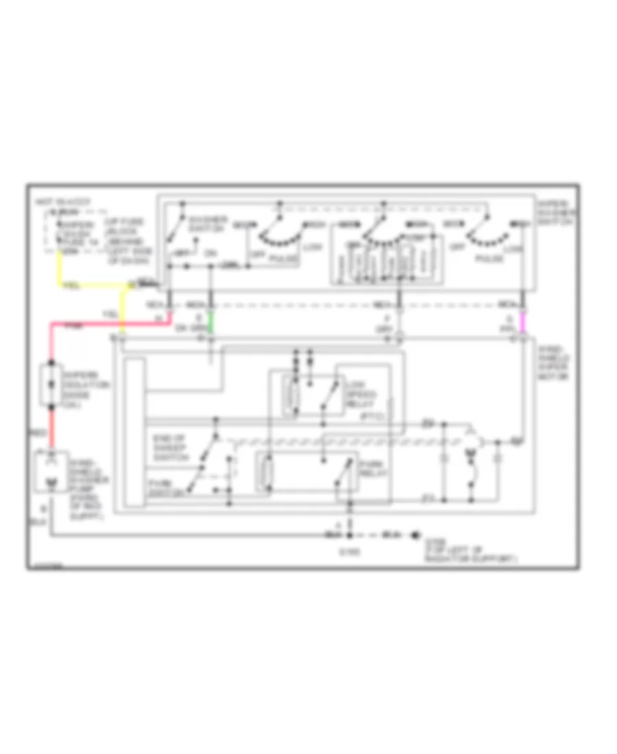
DEFOGGERS
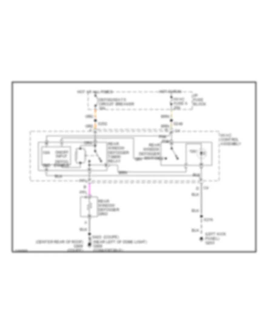
Defogger Wiring Diagram for Pontiac Firebird Trans Am 2001
List of elements for Defogger Wiring Diagram for Pontiac Firebird Trans Am 2001:
- "on"
- (coupe)
- (left kick panel) g200
- (near left of dome light) g909 (convertible)
- Defog enable
- Defog/seats circuit breaker 30a
- Gnd
- Hot at all times
- Hot in run
- Hvac control assembly
- Hvac fuse 6 20a
- I/p fuse block
- Ign
- On/off input
- Pnk
- Rear window defogger grid
- Rear window defogger switch
- Rear window defogger timer/ relay
- S216
- S248
- S252
- S420
ENGINE PERFORMANCE
3.8L
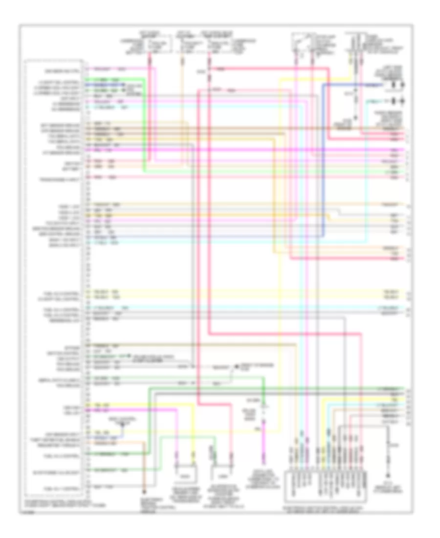
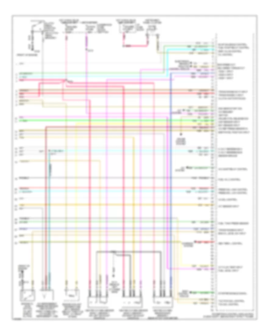
3.8L VIN K, Engine Performance Wiring Diagrams (1 of 4) for Pontiac Firebird Trans Am 2001
List of elements for 3.8L VIN K, Engine Performance Wiring Diagrams (1 of 4) for Pontiac Firebird Trans Am 2001:
- (front of engine) g125
- (left side of cyl block) knock sensor (ks) bank 1
- 1-2 shift sol control
- 18x ref
- 18x reference
- 2-3 shift sol control
- 2nd gear ind ctrl
- 3x ref
- 3x reference
- Bank 1 ks input
- Bank 2 ks input
- Battery
- Body control module
- Bypass
- Ckp 18x sig
- Ckp sync sig
- Cmp input
- Cmp output
- Cmp signal
- Cooling fan system
- Cruise module, radio & inst cluster
- Data link connector (under dash, to the right of steering column)
- Ect sensor ground
- Egr control ground
- Egr pos sensor ground
- Electronic brake & traction control module
- Electronic ignition control module (icm) (at front end of left cylinder head)
- Eng ctrl fuse 15a
- Evap purge valve cont
- Evaporative emissions (evap) canister purge solenoid (right front of eng, next to inj 2)
- Fuel inj 1 control
- Fuel inj 2 control
- Fuel inj 4 control
- Fuel inj 5 control
- Fuel inj 6 control
- G114 (rear of left cylinder head)
- G125 (front of engine)
- Ground
- Hi speed cool fan cont
- Ho2s 1 low
- Ho2s 2 low
- Hot at all times
- Hot in run & start
- Hot in run, bulb test & start
- Iat sensor ground
- Ign
- Ign control
- Ign voltage
- Ignition
- Ignition control
- Knock sensor (ks) bank 2 (right side of cyl block)
- Lo speed cool fan cont
- Maf sensor input
- Map sensor ground
- Mass airflow (maf) sensor (in air duct, front of int manifold)
- Pcm batt fuse 10a
- Pcm ground
- Pcm ign fuse 15a
- Pnk
- Pnk a
- Powertrain control module (pcm) (in eng compt, behind right strut tower)
- Ref low
- Reference low
- Requested torque in
- S101
- S107
- S108
- S110
- S182
- Serial data (class 2)
- Signal
- Splice pack sp200
- Stoplamp switch (on brake pedal support) c2
- Tac serial data
- Tan
- Tcc switch input
- Theft deter fuel enable
- Trans range a input
- Underhood fuse block (bottom)
- Underhood fuse block (top)
- Vehicle speed sensor (vss) (on rear side of transmission)
- Vss high
- Vss low
- Vss output
3.8L VIN K, Engine Performance Wiring Diagrams (2 of 4) for Pontiac Firebird Trans Am 2001
List of elements for 3.8L VIN K, Engine Performance Wiring Diagrams (2 of 4) for Pontiac Firebird Trans Am 2001:
- (eng harn, approx 2 cm from inj 3 breakout)
- (under console near
- 1-2 shift sol
- 2-3 shift sol
- 2nd gear ind
- 3-2 shift sol
- A/t fluid pressure manual valve position switch
- A/t fluid temp sensor
- All times
- Automatic transaxle
- B pnk
- Camshaft position sensor (cmp) (engine front cover)
- Control solenoid
- Crankshaft position sensor (ckp) (lower front of eng)
- Fuel injectors
- G125 (front of eng)
- G125 (front of engine)
- Gauge fuse 9 20a
- Hot at
- Hot in run
- Hot in run, bulb test & start
- I/p fuse block
- Inj 1 fuse 15a
- Pnk
- Pressure a
- Red
- Rev
- S102 pnk
- S144 (eng harn, approx 4 cm from inj 3 breakout)
- S145
- S154
- S206
- S215
- S234 (i/p harn, 5 cm from bcm breakout)
- Second gear start switch
- Shift control lever) park/neutral position (pnp) switch
- Stop/ hazard fuse 1 20a
- Stoplamp switch (on brake pedal bracket)
- Tan
- Tcc pwm sol
- Tcc sol
- Underhood fuse block (bottom)
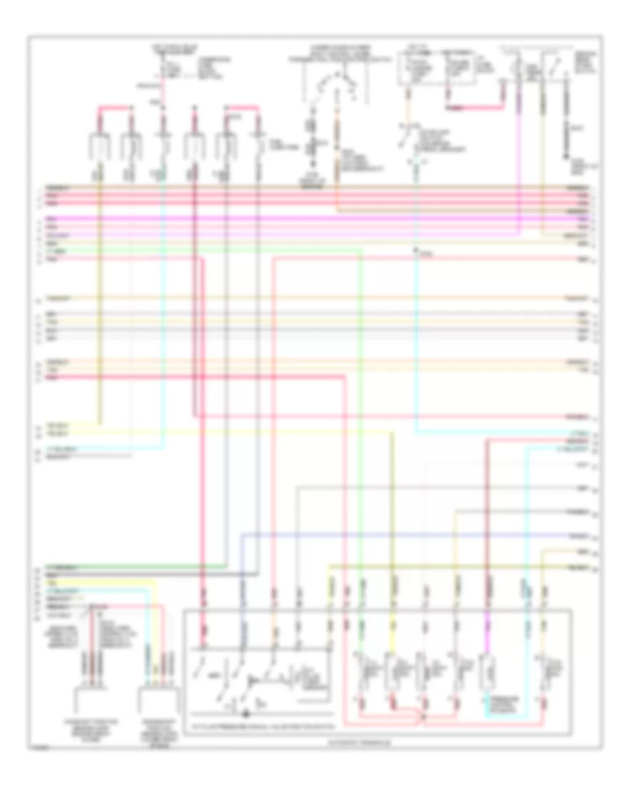
3.8L VIN K, Engine Performance Wiring Diagrams (3 of 4) for Pontiac Firebird Trans Am 2001
List of elements for 3.8L VIN K, Engine Performance Wiring Diagrams (3 of 4) for Pontiac Firebird Trans Am 2001:
- (eng harn, approx 3 cm from inj 5 breakout)
- (eng harn, approx 8 cm from pcm breakout)
- (front of engine)
- (i/p harn, coupe: 40 cm conv: 46 cm from i/p pass through in-line connector that is forward of rear axle)
- (on air intake duct, forward of intake manifold) intake air temperature (iat) sensor
- (top right of engine) evaporative emissions canister vent solenoid
- 5v ref
- A10
- B10
- Brake sw
- Cruise control system
- Etc fuse 10a
- Exhaust gas recirculation (egr) valve (left front of engine)
- Fuel level sensor
- Fuel pump
- Fuel pump fuse 20a
- Fuel pump relay
- Fuel tank pressure sensor
- Fuel tank unit
- Fused input
- G125
- G125 (front of engine)
- G309 (left door sill)
- Ground
- Hot at all times
- Hot in run, bulb test & start
- Manifold absolute pressure (map) sensor (right side of intake manifold)
- Motor driver
- Nca
- On/off
- Pnk
- Red
- Res/acc
- S101
- S117
- S121
- S171
- S244
- Set/coast sig
- Tac ser data
- Tan
- Tcs batt fuse 20a
- Throttle actuator control
- Throttle actuator control module (on accelerator pedal bracket)
- Tp sens 1
- Tps 2 gnd
- Tps 2 sig
- Tps1 gnd
- Under- hood fuse block (bottom)
- Under- hood fuse block (top)
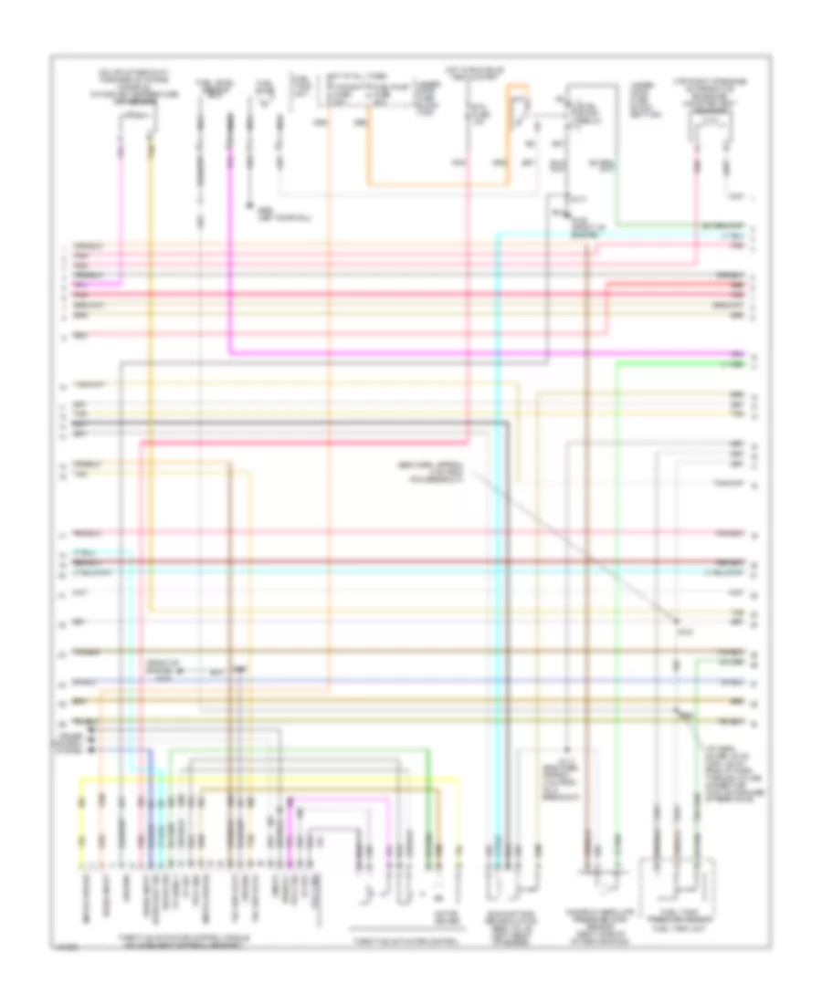
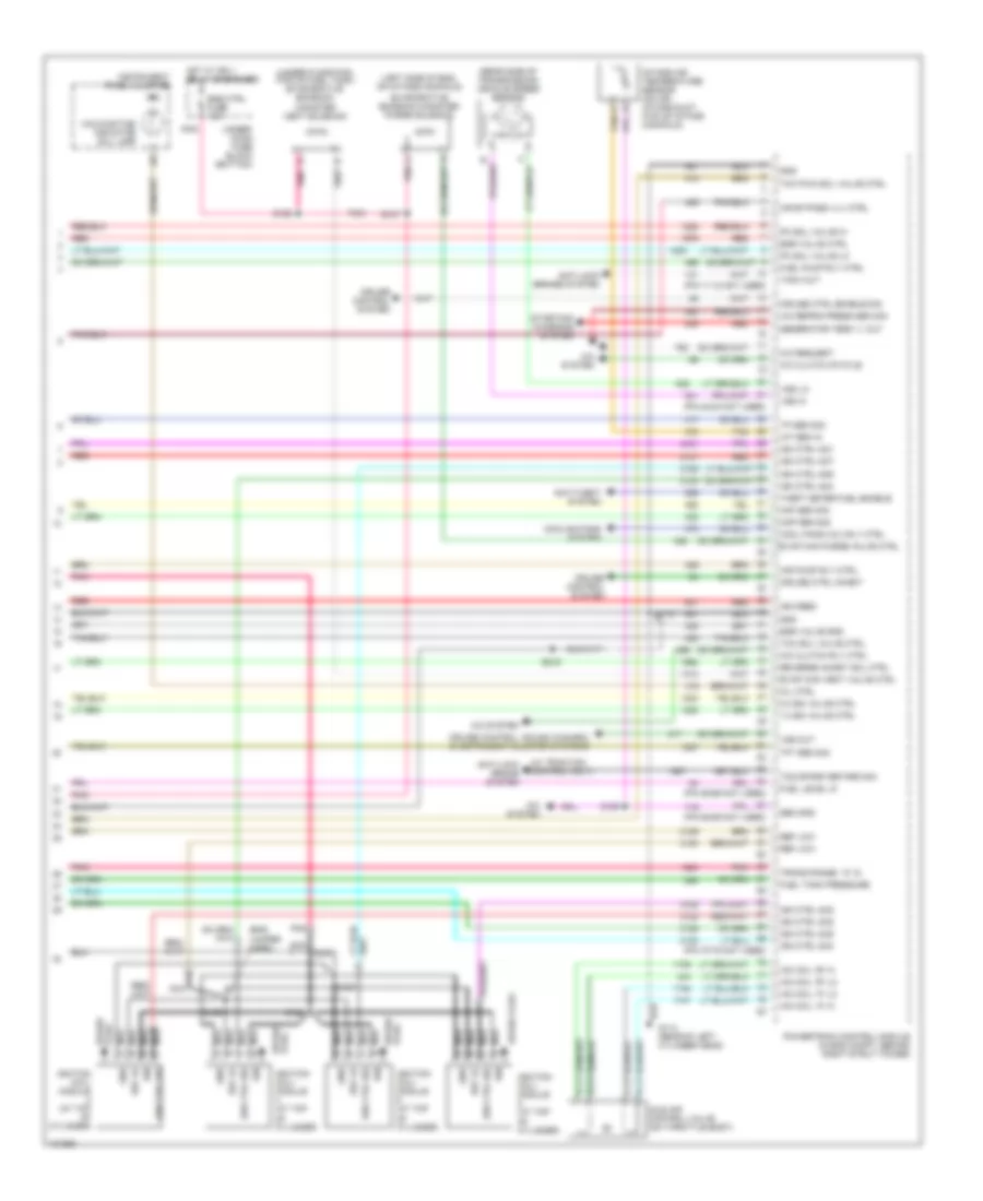
3.8L VIN K, Engine Performance Wiring Diagrams (4 of 4) for Pontiac Firebird Trans Am 2001
List of elements for 3.8L VIN K, Engine Performance Wiring Diagrams (4 of 4) for Pontiac Firebird Trans Am 2001:
- (front of engine)
- (front of engine) g125
- 2nd gear start sig
- 3-2 sol control
- 5 volt reference a
- 5 volt reference b
- A/c comp relay control
- A/c ref press sensor in
- A/c refrigerent pressure sensor (above right front wheelwell, attached to refrigerent line)
- A/c request
- A/c system
- A/t fluid temp input
- Body control module
- Charging system
- Clutch anticipate sig
- Clutch pedal position switch (on clutch pedal bracket)
- Cruise control system
- Cruise ctrl release sig
- Delivered torque out
- Ect sensor input
- Egr pintel position input
- Egr valve control
- Electronic brake & traction control module
- Eng oil level sw input
- Eng sen fuse 20a
- Eng speed out
- Engine coolant temperature (ect) sensor (below throttle body, at front of eng)
- Engine oil level switch (in left side of oil pan)
- Evap solenoid control
- Fuel inj 3 control
- Fuel level input
- Fuel pump relay control
- Fuel tank press sensor
- G114 (rear of left cylinder head)
- G125
- Gauges fuse 9 10a
- Gen term l control
- Heated oxygen sensor bank 1 sensor 1 (on left exhaust manifold)
- Heated oxygen sensor bank 2 sensor 1 (on right exhaust manifold)
- Heated oxygen sensor bank sensor 3 (rear of cat converter)
- Ho2s 1 input
- Ho2s 2 input
- Hot in run, bulb test & start
- Hot in start
- I/p fuse block
- Iat sensor input
- Ignition
- Instrument panel cluster
- Map sensor input
- Mil control
- Mil ind
- Nca
- Pnk
- Powertrain control module (pcm) (in eng compt, behind right strut tower)
- Press sol high control
- Press sol low control
- Red
- S104
- S108
- S110
- S111
- S170
- S206
- Sensor ground
- Starter enable signal
- Strtr fuse 15a
- Tan
- Tcc pwm sol control
- Tcc sol control
- Trans range b input
- Trans range c input
- Trans range sw p input
- Underhood fuse block (bottom)
5.7L
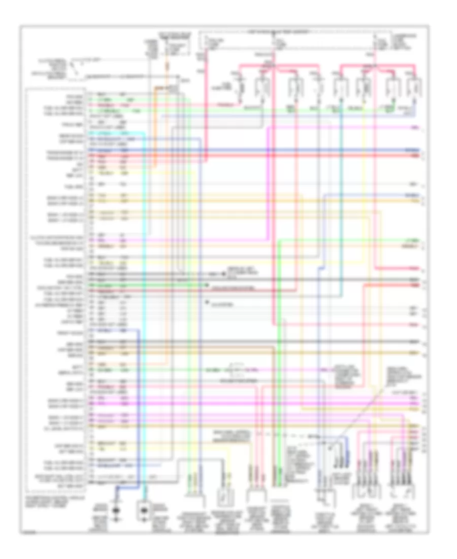
5.7L VIN G, Engine Performance Wiring Diagrams (1 of 4) for Pontiac Firebird Trans Am 2001
List of elements for 5.7L VIN G, Engine Performance Wiring Diagrams (1 of 4) for Pontiac Firebird Trans Am 2001:
- (587)
- (eng harn, a/t: approx 8 cm from a/t breakout, m/t: approx 9 cm from vss breakout)
- (eng harn, approx 15 cm from map sensor breakout)
- (eng harn, approx 9 cm from map sensor breakout) s116
- (pin 13-16 not used)
- (pin 38-39 not used)
- (pin 49-50 not used)
- (pin 5-7 not used)
- (pin 62-64 not used)
- (pin 9-10 not used)
- (rear of left cylinder head) g114
- 5v feed
- A/c refrig press 5v ref
- A/c system
- Anti-lock brakes system
- Bank 1 left front heated oxygen sensor (in left exhaust manifold)
- Bank 1 left rear heated oxygen sensor (rear of left catalytic converter)
- Bank 1 lf ho2s hi
- Bank 1 lf ho2s lo
- Bank 1 lr ho2s hi
- Bank 1 lr ho2s lo
- Bank 2 rf ho2s hi
- Bank 2 rf ho2s lo
- Bank 2 rr ho2s hi
- Bank 2 rr ho2s lo
- Batt
- Camshaft position sensor (top center rear of eng)
- Ckp sen sig
- Clutch anticipate sw sig
- Clutch pedal position switch (on clutch pedal bracket)
- Cmp sen sig in
- Cooling fan 1 rly ctrl
- Cooling fans system
- Crankshaft position sensor (right rear of eng, behind starter)
- Data link connector (under dash, right of steering column)
- Ect sen gnd
- Ect sen sig
- Egr sen gnd
- Egr sig
- Engine coolant temperature sensor (left side of eng, above generator)
- Front ks sig
- Fuel gnd
- Fuel inj driver no1
- Fuel inj driver no2
- Fuel inj driver no3
- Fuel inj driver no4
- Fuel inj driver no5
- Fuel inj driver no6
- Fuel inj driver no7
- Fuel inj driver no8
- Fuel injectors
- Hot in run, bulb test & start
- Hot in run, bulb test or start
- Ign
- Ign feed
- Inj1 fuse 15a
- Inj2 fuse 15a
- Knock sensor (center of eng, below manifold)
- Manifold absolute pressure sensor (rear of intake manifold)
- Map 5v ref
- Map sen gnd
- Nca
- Oil level switch in
- Pcm bat fuse 10a
- Pcm gnd
- Pcm ign fuse 15a
- Pnk
- Pnk a
- Pnk d
- Pnk s102
- Pnp sw sig
- Powertrain control module (in eng compt, behind right strut tower)
- Rear ks sig
- Red
- Red c
- Ref low
- S106
- S109
- S110
- S118
- S119
- S215
- Sen gnd
- Serial data
- Skip shift sol ctrl (m/t) 3-2 ss valve ctrl (a/t)
- Splice pack sp200
- Tan
- Tcc/cruise brake sw in
- Throttle position sensor (on throttle body)
- Tps 5v ref
- Trans range "b" in
- Trans range "c" in
- Under- hood fuse block (top)
- Underhood fuse block (bottom)
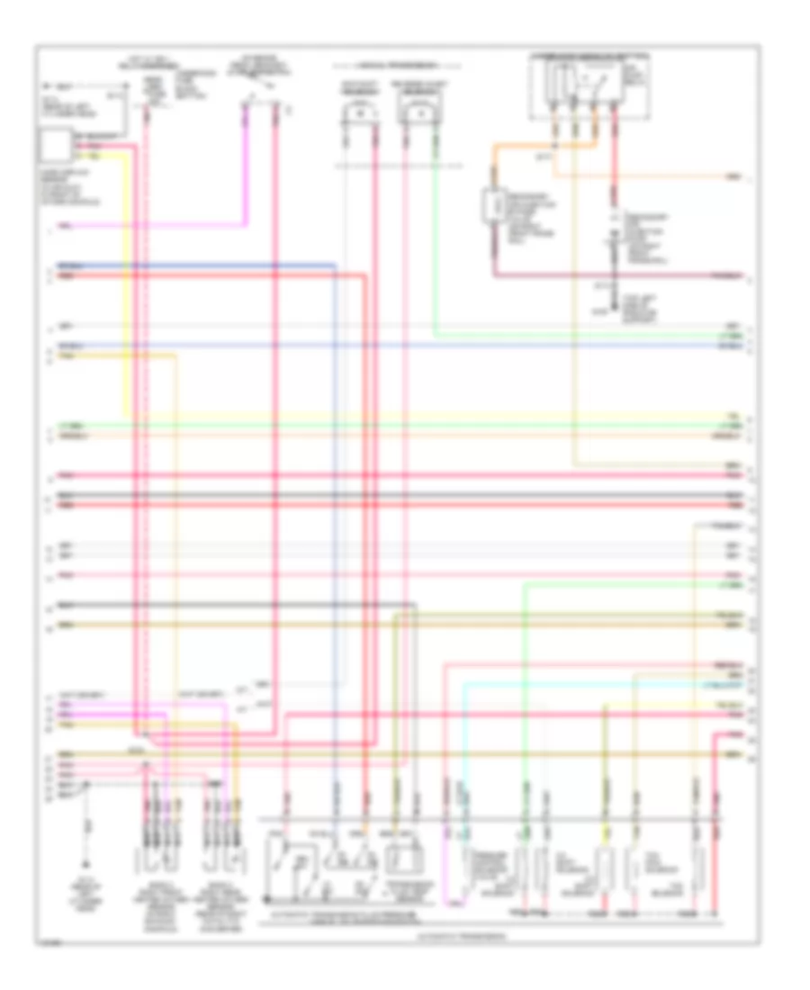
5.7L VIN G, Engine Performance Wiring Diagrams (2 of 4) for Pontiac Firebird Trans Am 2001
List of elements for 5.7L VIN G, Engine Performance Wiring Diagrams (2 of 4) for Pontiac Firebird Trans Am 2001:
- (on brake pedal bracket) stoplamp switch
- (top left side of radiator support)
- 1-2 shift solenoid
- 2-3 shift solenoid
- 3-2 shift solenoid
- A/t
- Air pump relay
- Automatic transmission
- Automatic transmission fluid pressure
- B pnk
- Bank 2 right front heated oxygen sensor (in right exhaust manifold)
- Bank 2 right rear heated oxygen sensor (rear of right catalytic converter)
- D2 sw
- D3 sw
- D4 sw
- Eng sen fuse 20a
- G108
- G114 (rear of left cylinder head)
- Hot w/ ign 1 relay energized
- Lo sw
- M/t
- Manual transmission
- Manual valve position switch
- Mass airflow sensor (in air duct, in front of intake manifold)
- Nca
- Pessure control solenoid valve
- Pnk
- Red
- Red a
- Rev sw
- Reverse inhibit solenoid
- S104
- S108
- S110
- S177
- Secondary air injection bypass valve (on right front frame rail)
- Secondary air injection pump (on right front frame rail)
- Skip shift solenoid
- Tan
- Tcc pwm solenoid
- Tcc solenoid
- Transmission fluid temp sensor
- Underhood fuse block (bottom)
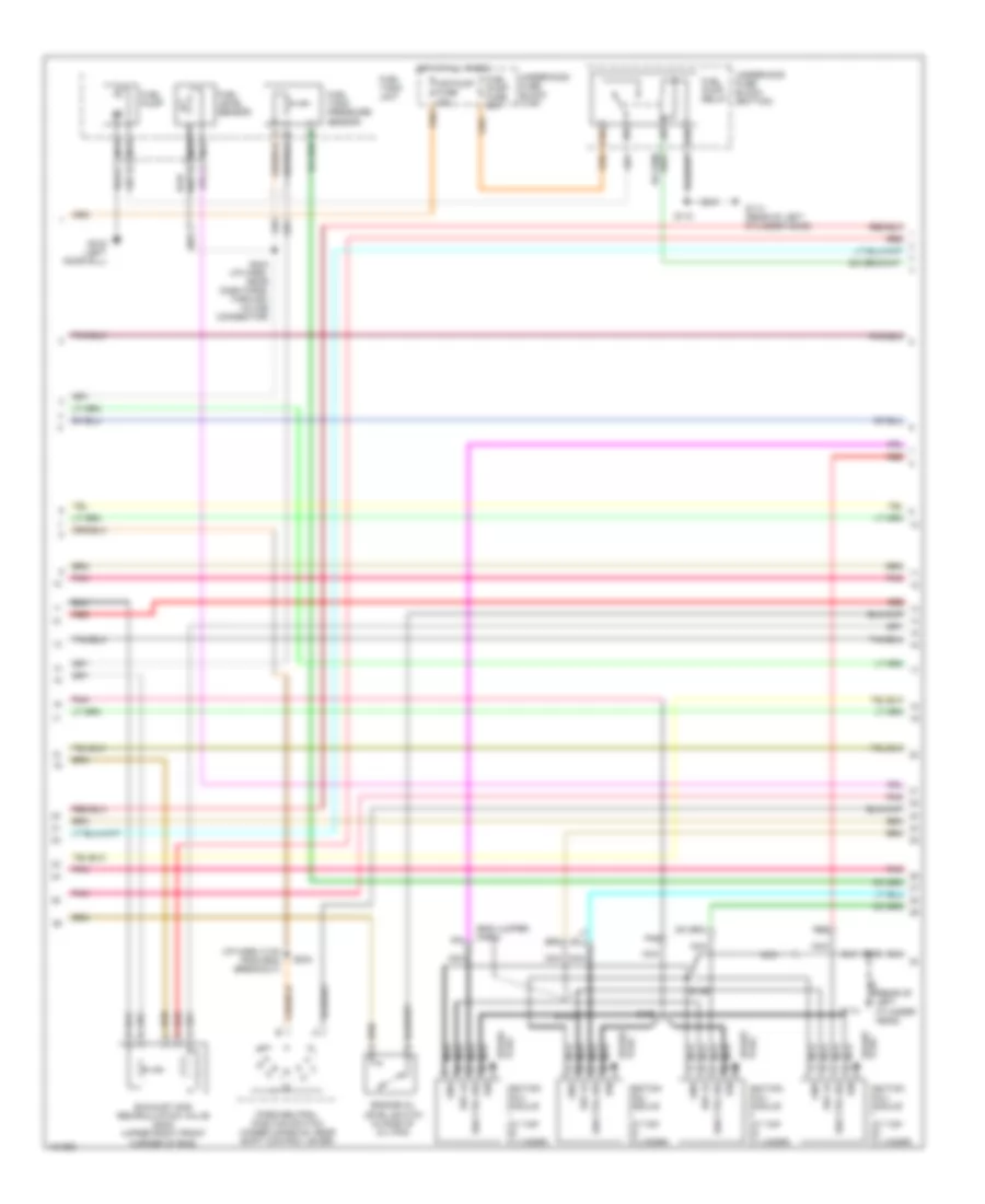
5.7L VIN G, Engine Performance Wiring Diagrams (3 of 4) for Pontiac Firebird Trans Am 2001
List of elements for 5.7L VIN G, Engine Performance Wiring Diagrams (3 of 4) for Pontiac Firebird Trans Am 2001:
- (eng jumper harn)
- (i/p harn, 5 cm from bcm breakout)
- (rear of left cylinder head)
- A10
- Air pump fuse 30a
- B10
- Engine oil level switch (in side of oil pan)
- Exhaust gas recirculation valve (2000) (upper right front corner of eng)
- Fuel level sensor
- Fuel pump
- Fuel pump fuse 20a
- Fuel pump relay
- Fuel tank pressure sensor
- Fuel tank unit
- G114
- G114 (rear of left cylinder head)
- G316 (left door sill)
- Gnd
- Hot at all times
- Ign
- Ign ctrl sig
- Ignition coil/ module (at top of cylinder)
- Nca
- Park/neutral position switch (under console, near shift control lever)
- Plug spark
- Pnk
- Red
- Red e
- Ref lo
- S100
- S110
- S122
- S123
- S126
- S234
- S244 (i/p harn, near dash pass- through in-line connector)
- Spark plug
- Underhood fuse block (bottom)
- Underhood fuse block (top)
5.7L VIN G, Engine Performance Wiring Diagrams (4 of 4) for Pontiac Firebird Trans Am 2001
List of elements for 5.7L VIN G, Engine Performance Wiring Diagrams (4 of 4) for Pontiac Firebird Trans Am 2001:
- (eng jumper harn)
- (left side of eng, on intake manifold)
- (mil)
- (pin 11-12 not used)
- (pin 22-23 not used)
- (pin 55-56 not used)
- (pin 58-59 not used)
- (pin 70-75 not used)
- (rear side of transmission) vehicle speed sensor
- (under floor pan, fwd of fuel tank) evaporative emission canister vent solenoid
- (w/ traction control only)
- 1-3 ss valve ctrl
- 2-3 ss valve ctrl
- A pnk
- A/c clutch rly ctrl
- A/c clutch status
- A/c refrig press sen sig
- A/c request
- A/c system
- Air bypass vlv ctrl
- Air pump rly ctrl
- Anti-lock brake system
- Anti-lock brakes system
- Anti-theft system
- Cool fans 2 & 3 rly ctrl
- Cooling fans system
- Cruise control system
- Cruise control, sound (camaro) & instrument cluster systems
- Cruise ctrl enable sig
- Cruise ctrl inhibit
- Egr valve ctrl
- Egr valve gnd
- Eng ctrl fuse 15a
- Evap can purge valve ctrl
- Evap can vent valve ctrl
- Evaporative emission canister purge solenoid
- Fuel level in
- Fuel pump rly ctrl
- Fuel tank pressure
- G114 (rear of left cylinder head)
- Generator term "l" out
- Gnd
- Hot w/ ign 1 relay energized
- Iac coil "a" hi
- Iac coil "a" lo
- Iac coil "b" hi
- Iac coil "b" lo
- Iat sen in
- Idle air control valve (on throttle body)
- Ign
- Ign ctrl no1
- Ign ctrl no2
- Ign ctrl no3
- Ign ctrl no4
- Ign ctrl no5
- Ign ctrl no6
- Ign ctrl no7
- Ign ctrl no8
- Ign ctrl sig
- Ign feed
- Ignition coil/ module (at top of cylinder)
- Instrument panel cluster
- Intake air temperature sensor (on air intake duct, fwd of intake manifold)
- Maf sen sig
- Malfunction indicator lamp
- Map sen sig
- Mil ctrl
- Nca
- Pc sol valve hi
- Pc sol valve lo
- Plug spark
- Pnk
- Powertrain control module (in eng compt, behind right strut tower)
- Red
- Ref lo
- Ref low
- Reverse inhibit sol ctrl
- S107
- S110
- S124
- S125
- S127
- S128
- S182
- S215
- Sen gnd
- Spark plug
- Starting/ charging system
- Tach out
- Tan
- Tcc pwm sol valve ctrl
- Tcc sol valve ctrl
- Tcs spark retard sig
- Tft sen sig
- Theft deter fuel enable
- Tp sen sig
- Trans range "a" in
- Under- hood fuse block (bottom)
- Vss hi
- Vss lo
- Vss out
EXTERIOR LIGHTS
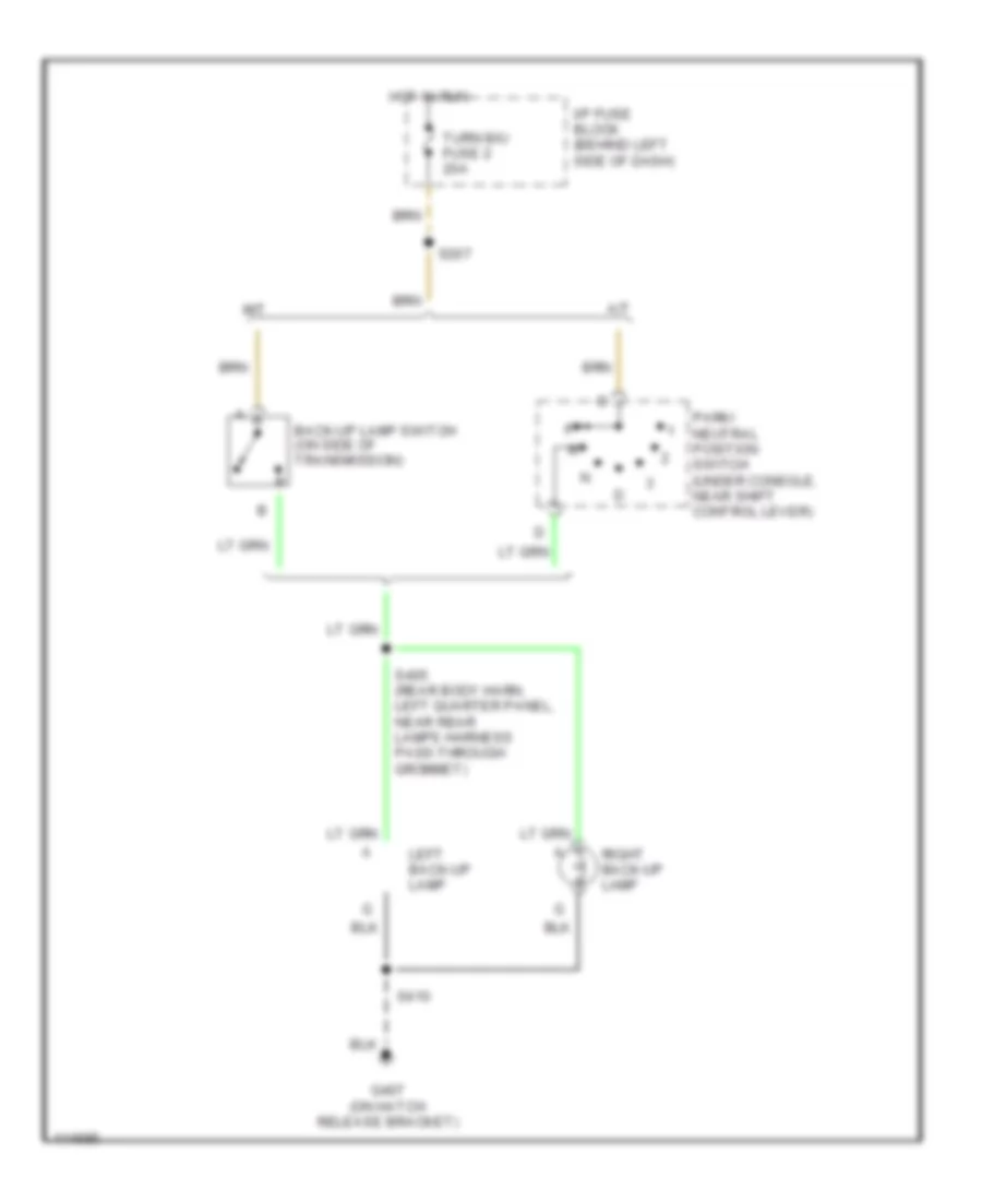
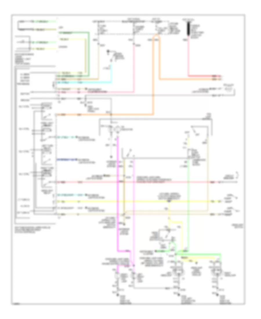
Back-up Lamps Wiring Diagram for Pontiac Firebird Trans Am 2001
List of elements for Back-up Lamps Wiring Diagram for Pontiac Firebird Trans Am 2001:
- A/t
- Back-up lamp switch (on side of transmission)
- G407 (on hatch release bracket)
- Hot in run
- I/p fuse block (behind left side of dash)
- Left back-up lamp
- M/t
- Park/ neutral position switch (under console, near shift control lever)
- Right back-up lamp
- S207
- S405 (rear body harn, left quarter panel, near rear lamps harness pass-through grommet)
- S410
- Turn b/u fuse 2 20a
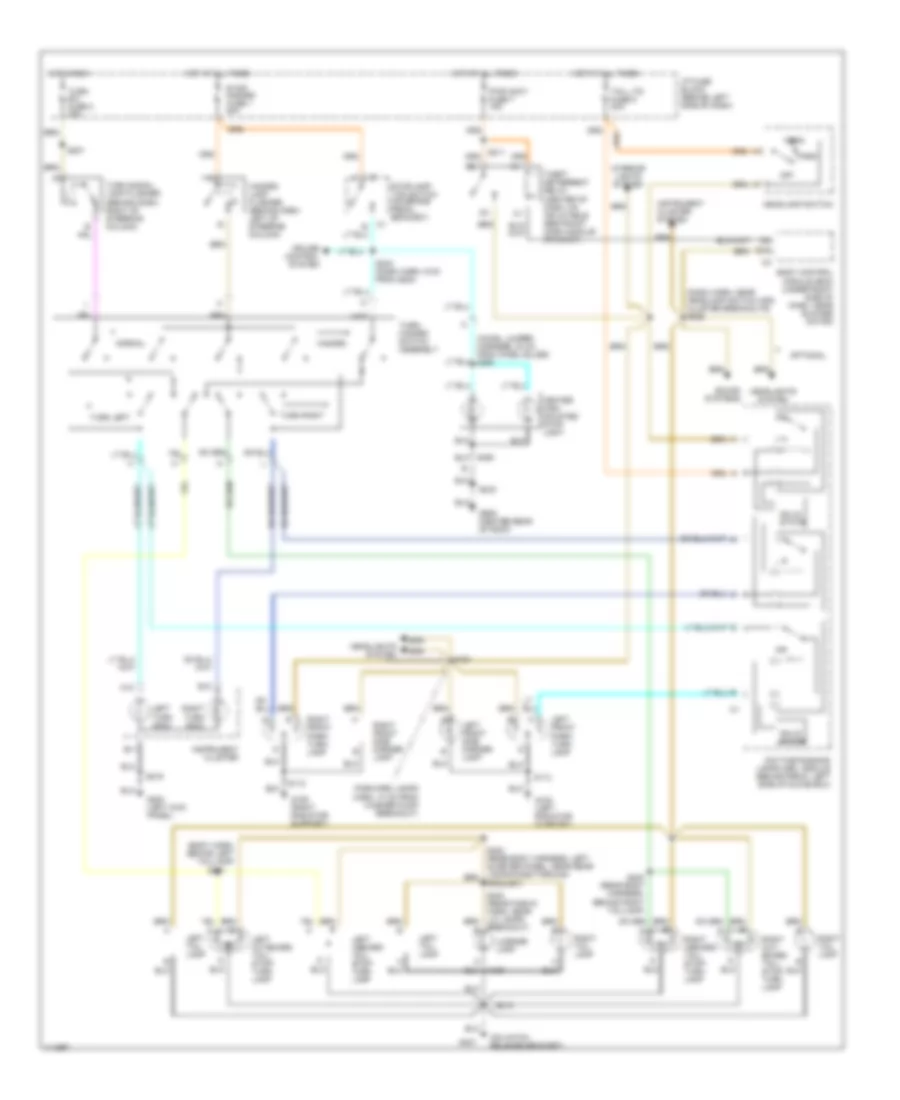
Exterior Lamps Wiring Diagram for Pontiac Firebird Trans Am 2001
List of elements for Exterior Lamps Wiring Diagram for Pontiac Firebird Trans Am 2001:
- (body harn, behind left taillamp)
- (chmsl jumper harness, 30 cm from chmsl bulbs) s460
- (dash harn, near headlamp switch and cluster breakouts) s226
- (forward lamps harn, 10 cm from washer pump breakout)
- (on hatch release bracket)
- A12
- B10
- B11
- Body control module (bcm) (under right side of dash, near blower motor)
- Breakout)
- Center high mounted stop light
- Cruise control system
- D15
- Daytime running lamps (drl) module (behind radio, left side of glove box)
- G108 (left radiator support)
- G109 (right radiator support)
- G200 (left kick panel)
- G407
- G909 (center rear of roof)
- Grommet)
- Hazard
- Hazard lamp flasher (behind dash, left of steering column)
- Head
- Headlamp switch
- Headlights system
- Hot at all times
- Hot in run
- I/p fuse block (behind left side of dash)
- Instrument cluster
- Instrument cluster system
- Interior lights system
- Left front park/ turn lamp
- Left front side marker lamp
- Left inboard tail/ stop/ turn lamp
- Left outboard tail/ stop/ turn lamp
- Left tail lamp
- Left turn indic
- License lamp
- Normal
- Off
- Optional
- Orn
- Park
- Pwr accy fuse 7 15a
- Right front park/ turn lamp
- Right front side marker lamp
- Right inboard tail/ stop/ turn lamp
- Right out- board tail/ stop/ turn lamp
- Right tail lamp
- Right turn indic
- S112
- S113
- S150
- S207
- S211
- S216
- S243 (dash harn, 9 cm from g200)
- S401
- S402 (rear body harness, behind right taillamp)
- S410
- S420
- S450
- Solid state
- Sound systems
- Stop/ hazard fuse 1 20a
- Stoplamp/ tcc switch (on brake pedal bracket)
- Tail lts fuse 5 20a
- Theft deterrent relay (center of dash, on inflatable restraint dash module bracket)
- Turn b/u fuse 2 20a
- Turn left
- Turn right
- Turn signal lamp flasher (behind dash, right of steering column)
- Turn/ hazard switch assembly
GROUND DISTRIBUTION
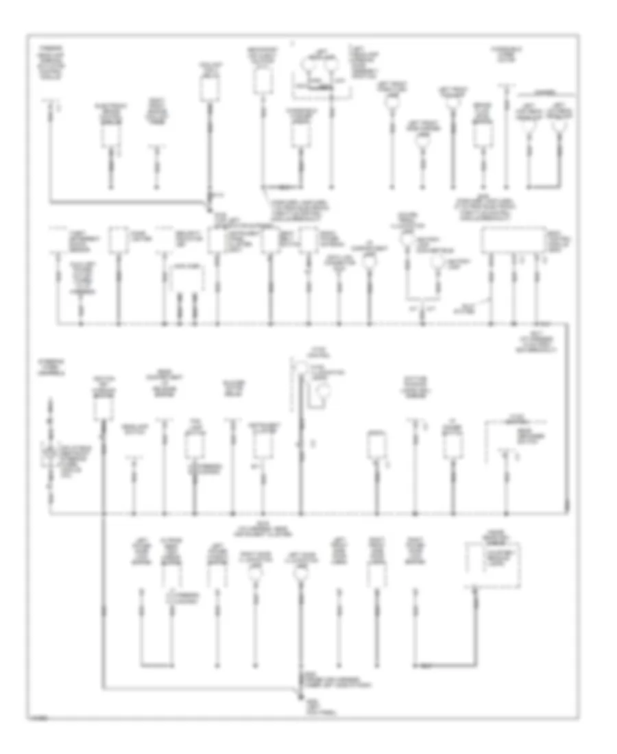
Ground Distribution Wiring Diagram (1 of 3) for Pontiac Firebird Trans Am 2001
List of elements for Ground Distribution Wiring Diagram (1 of 3) for Pontiac Firebird Trans Am 2001:
- (eng harn, 15 cm from pcm breakout)
- (eng harn, approx 15 cm from g114) s108
- (forward lamp harn, near right frt shock tower)
- 3.8l (vin k)
- 5.7l (vin g)
- A/c clutch diode
- A/c compressor clutch
- A18
- Accelerator & servo control module (asm)
- B10
- B15
- Battery
- Braided
- Camaro
- Clutch pedal position switch
- Clutch pedal position switch d
- Connector breakout)
- Cruise control module
- Data link connector (dlc)
- Electronic brake control module (ebcm)
- Electronic ignition control module (icm)
- Engine oil level switch
- Engine oil pressure sensor
- Firebird
- Fuel pump relay
- G102 (left front shock tower)
- G103 (right front shock tower)
- G109 (top right of radiator support)
- G112 (lower left side of engine)
- G113 (left front frame rail)
- G114 (left rear of engine)
- G119 (right front of engine)
- G120 (right side of engine block)
- G302 (below center console)
- Heated oxygen sensor (ho2s) bank 1 sensor 1
- Heated oxygen sensor (ho2s) bank 1 sensor 2
- Heated oxygen sensor (ho2s) bank 2 sensor 1
- Heated oxygen sensor (ho2s) bank 2 sensor 2
- High nca
- Horn
- Ignition control coils/module bank 1
- Ignition control coils/module bank 2
- Ignition relay
- Inflatable restraint sensing & diagnostic module (sdm)
- Instrument cluster
- Low nca
- Mass airflow (maf) sensor
- Park/ neutral position switch
- Powertrain control module (pcm)
- Right front fog lamp
- Right front park/turn lamp
- Right front side marker lamp
- Right headlamp opening door assembly
- Right headlight
- Right high beam headlamp
- Right low beam headlamp
- S100
- S101
- S108 (engine harn, near trans connector breakout)
- S110 (engine harness, 20 cm from pcm breakout)
- S110 (engine harness, 4 cm from pcm breakout)
- S115 (eng harn, side of eng, near a/c comp)
- S115 (engine harness, side of engine, near a/c comp)
- S215 (i/p harness, 11 cm from antenna cable breakout)
- Second gear start switch (chevy w/o nw9)
- Throttle actuator control (tac) module
- Traction control switch
- Traction control switch (chevy w/nw9)
Ground Distribution Wiring Diagram (2 of 3) for Pontiac Firebird Trans Am 2001
List of elements for Ground Distribution Wiring Diagram (2 of 3) for Pontiac Firebird Trans Am 2001:
- (coupe) prndl illumination lamp
- (forward lamp harn, 7 cm from electronic throttle control module breakout)
- A (firebird) (camaro)
- A/t
- Amplifier
- Ashtray lamp
- Ashtray lamp (convertible)
- Auxiliary power outlet (taped to i/p harness)
- B10
- B11
- B15
- Blower motor relay
- Body control module (bcm)
- Brake fluid level switch
- Camaro
- Cigar lighter
- Coolant fan 3 relay
- Courtesy/ reading lamps
- D14
- Data link connector (dlc)
- Daytime running lamps (drl) module
- Electronic brake control module
- Firebird
- Fog lamp switch
- G108 (top left of radiator support)
- G200 (left kick panel)
- Gulf states
- Headlamp opening actuator control module
- Headlamp switch
- High
- Hvac control
- Hvac illumination lamps
- I/p compartment lamp
- I/p dimmer switch
- Ignition key warning switch
- Inflatable restraint steering wheel module coil
- Inside rearview mirror
- Instrument cluster
- Instrument panel cluster (2001)
- Left door illumination lamp
- Left front fog lamp
- Left front park/turn lamp
- Left front side door lock
- Left front side marker lamp
- Left headlamp
- Left headlamp opening door assembly (pontiac)
- Left high beam headlamp
- Left low beam headlamp
- Left power door lock switch
- Left power window switch
- Low
- M/t
- Nca
- Outside rear view mirror switch
- Radio
- Radio power antenna
- Rear compartment lid release switch
- Rear defogger switch
- Right door illumination lamp
- Right front engine coolant fans
- Right front side door lock
- Right power door lock switch
- S113
- S155 (forward lamp harn, 27 cm from electronic throttle control module breakout)
- S216 (i/p harness, near instrument cluster)
- S217 (i/p harness, 18 cm from bcm breakout)
- Seat belt switch
- Secondary air inject- ion pump (5.7l)
- Security indicator led
- Steering wheel controls
- Theft deterrent shock sensor
- Windshield washer pump
- Windshield wiper motor
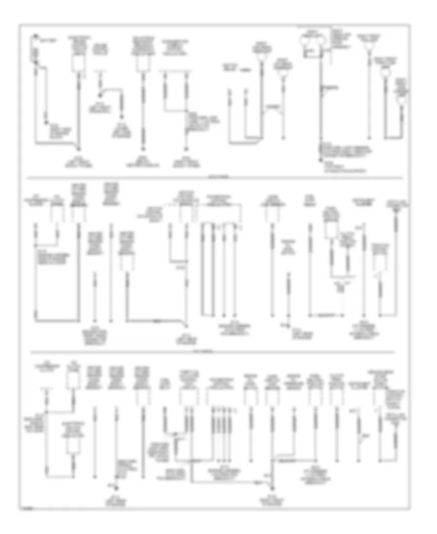
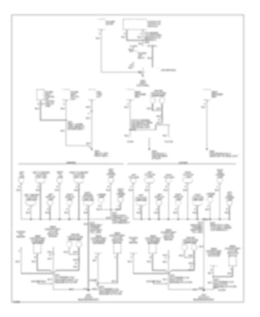
Ground Distribution Wiring Diagram (3 of 3) for Pontiac Firebird Trans Am 2001
List of elements for Ground Distribution Wiring Diagram (3 of 3) for Pontiac Firebird Trans Am 2001:
- (hatch harness, main branch, rear center of roof, near dome lamp) s420
- Blower motor
- Camaro
- Center high mounted stop lamp
- Convertible
- Coupe
- Firebird
- Folding top relay
- Folding top switch
- Folding top top switch (pontiac)
- From hatch release actuator)
- Fuel tank unit
- G203 (right kick panel)
- G300 (below left front seat)
- G407 (hatch release bracket)
- G407 (on hatch release bracket)
- G909 (convertible only) (near left of dome light)
- G909 (coupe only) (center rear of roof)
- Left back-up lamp
- Left inboard tail/stop/ turn lamp
- Left outboard tail/stop/ turn lamp
- Left side marker lamp
- Left tail lamp
- Left tail/stop lamp
- Left tail/stop/ turn lamp
- License lamp
- Nca
- Power seat cushion air control module c2 (aq9)
- Power seat switch (ag1)
- Rear compartment lid ajar indicator switch
- Rear compartment lid release actuator
- Rear defogger grid
- Right back-up lamp
- Right inboard tail/stop/ turn lamp
- Right outboard tail/stop/ turn lamp
- Right side marker lamp
- Right tail lamp
- Right tail/stop lamp
- Right tail/stop/ turn lamp
- S321 (seat jumper harn, beneath driver's seat)
- S410 (rear body harness, near right tail lamp)
- S430 (rear facia harn, 12 cm from license lamp breakout)
- S430 (rear fascia harness, 12 cm from license lamp breakout)
- S470 (i/p harness, 6 cm from hatch release actuator)
- S470 (i/p harness, 6 cm from rear compt lid release actuator)
- W/ eta
- W/c49
- W/o c49
- W/o eta
HEADLIGHTS
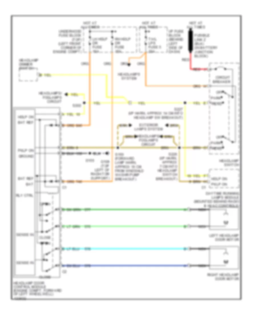
Headlamp Doors Wiring Diagram for Pontiac Firebird Trans Am 2001
List of elements for Headlamp Doors Wiring Diagram for Pontiac Firebird Trans Am 2001:
- Bat
- Bat ref
- Circuit breaker
- Close
- Daytime running lamps module (mounted behind radio & hvac controls)
- Exterior lamps system
- G108 (top left of radiator support)
- Ground
- Hdlp on
- Head
- Headlamp dimmer switch
- Headlamp door control module (engine compt, forward of left wheelwell)
- Headlamp switch
- Headlamps system
- Headlamps/ foglamps circuit
- Hot at all times
- I/p fuse block (behind left side of dash)
- Left headlamp door motor
- Lh hdlp dr fuse 15a
- Nca
- Off
- Open
- Park
- Pklp on
- Red
- Rh hdlp dr fuse 15a
- Right headlamp door motor
- Rly ctrl
- S150 (forward lamp harn, approx 16 cm from wndshld washr pump breakout)
- S155
- S202
- S226 (i/p harn, approx 7 cm into headlamp switch breakout)
- S227 (i/p harn, approx 14 cm into headlamp sw breakout)
- Sense in
- Tail lps fuse 5 20a
- Underhood fuse block (top) (left front corner of engine compt)
Headlight Wiring Diagram for Pontiac Firebird Trans Am 2001
List of elements for Headlight Wiring Diagram for Pontiac Firebird Trans Am 2001:
- (forward lamp harn, approx 16 cm from windshield washer pump breakout)
- (forward lamp harn, approx 4 cm from cruise control module) s160
- (forward lamp harn, approx 7cm from left front whl spd sens breakout)
- (i/p harn, approx 14 cm into headlamp switch breakout) s227
- (i/p harn, approx 7 cm into headlamp switch breakout)
- (not used)
- Al sens
- C nca
- Canada
- Circuit breaker
- Daytime running lamps ambient light sensor (top of dash)
- Daytime running lamps module (mounted behind radio & hvac controls)
- E11
- Exterior lights system
- F11
- Fog lamp relay (in top underhood fuse block)
- Fog lamp switch
- G108 (top left of radiator support)
- G109 (top right of radiator)
- G200 (left kick panel)
- Gauges fuse 9 10a
- Ground
- Head
- Head- lamp dimmer lo
- Headlamp door control module
- Headlamp switch
- Headlight relay
- Hl on in
- Hot at all times
- Hot in run
- Hot in run, bulb test or start
- I/p fuse block (behind left side of dash)
- Ignition
- Instrument cluster
- Instrument cluster system
- Interior lights system
- Left front fog lamp
- Left headlamp
- Left turn relay
- Lt turn in
- Nca
- Off
- On indicator
- Park
- Park brake switch
- Park light relay
- Pnk
- Prk brake
- Red
- Right front fog lamp
- Right headlamp
- Right turn relay
- Rly ctrl
- Rt turn in
- S112
- S150
- S152
- S155
- S202
- S206
- S207
- S216
- S226
- Sw illum
- Switch
- Tail lps fuse 5 20a
- Turn b/u fuse 2 20a
- Usa
HORN
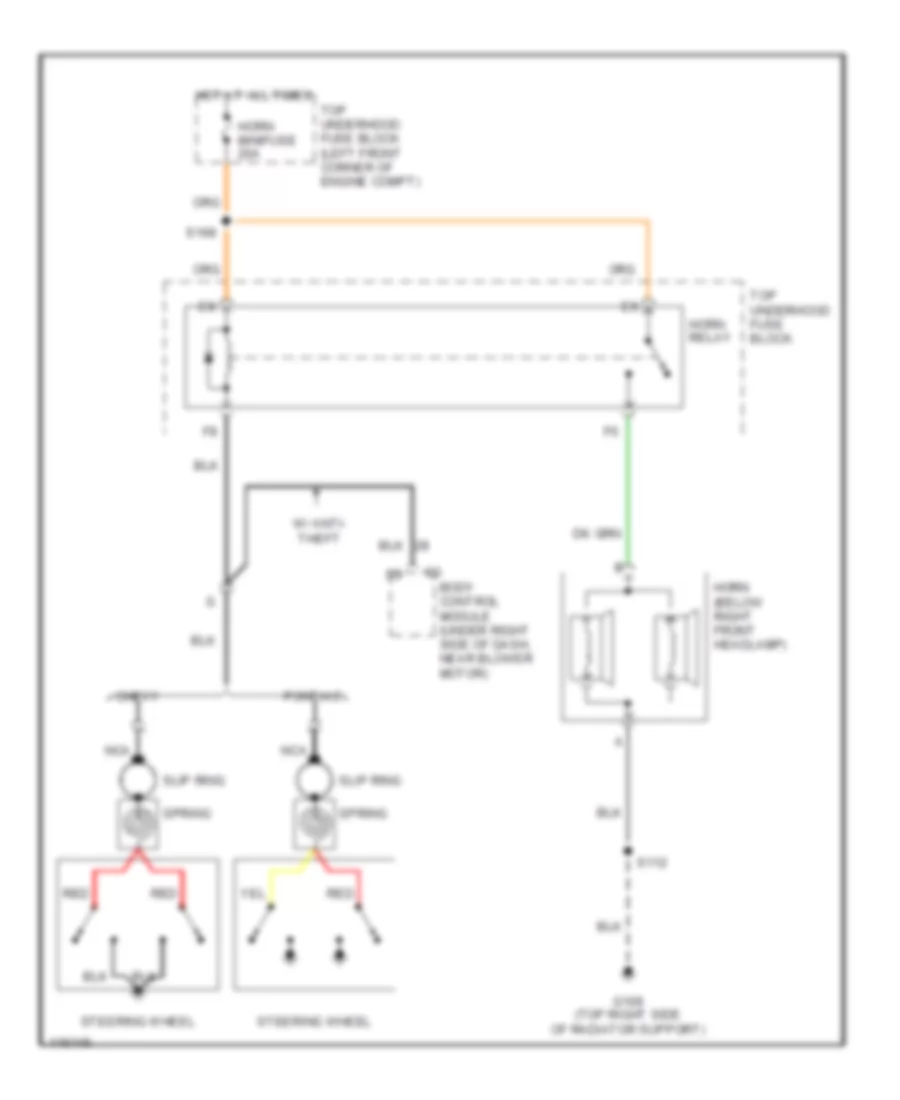
Horn Wiring Diagram for Pontiac Firebird Trans Am 2001
List of elements for Horn Wiring Diagram for Pontiac Firebird Trans Am 2001:
- Body control module (under right side of dash, near blower motor)
- Chevy
- G109 (top right side of radiator support)
- Horn (below right front headlamp)
- Horn minifuse 20a
- Horn relay
- Hot at all times
- Nca
- Pontiac
- Red
- S112
- S168
- Slip ring
- Spring
- Steering wheel
- Top underhood fuse block
- Top underhood fuse block (left front corner of engine compt)
- W/ anti- theft
INSTRUMENT CLUSTER
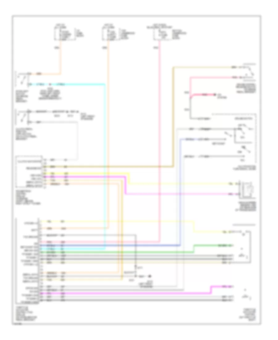
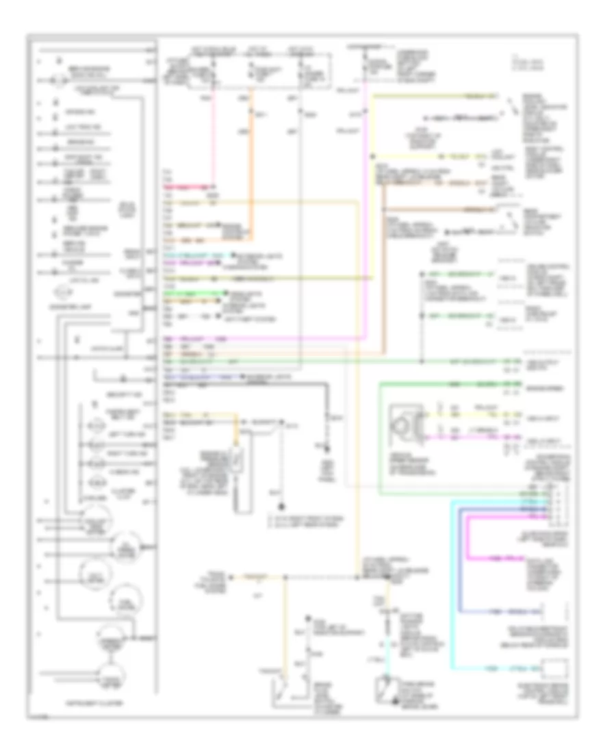
Instrument Cluster Wiring Diagram for Pontiac Firebird Trans Am 2001
List of elements for Instrument Cluster Wiring Diagram for Pontiac Firebird Trans Am 2001:
- (1999 vin g only)
- (5 bulbs)
- (i/p harn, approx 20 cm from rear compt lid release relay breakout)
- (on hatch release bracket)
- (on rear side of transmission)
- (pont) (chev)
- (right front of eng) (left rear of eng)
- (top right of radiator support)
- (vin k)
- 3.8l vin k
- 5.7l vin g
- A10
- A11
- A12
- A13
- A14
- A15
- A16
- A17
- Abs inop ind
- Air bag ind
- Anti-theft system
- B10
- B11
- B12
- B13
- B14
- B15
- B16
- B17
- Body control module (under right side of dash, near blower motor)
- Brake fluid level switch (in master cylinder)
- Brake ind
- C15
- Change oil
- Check gauges ind
- Class 2 data
- Cluster illum
- Coolant temp gauge
- Crank input
- Cruise control module (in eng compt, on left frame rail forward of wheelwell)
- D13
- Data link connector (under dash, to right of steering column)
- Daytime running lights module (behind radio & hvac contrls, left of glove box)
- Electronic brake control module (top of left front frame rail)
- Engine controls system
- Engine coolant level indicator module (5.7l only) (mounted on upper right side of radiator)
- Engine oil pressure sensor (3.8l: lower right front of engine) (5.7l: on top rear b
- Engine speed
- Exterior lights system
- Fasten seat belt ind
- Fuel gauge
- G108 (top left of radiator support)
- G109
- G114
- G119
- G200 (left kick panel)
- G407
- Gauges fuse 9 10a
- Gnd
- Hatch ajar
- Headlights system
- Hi beam ind
- Hot at all times
- Hot in run, bulb test or start
- Hot in start
- Hot with lamps on
- I/p dimmer fuse 16 5a
- I/p fuse block (behind left side of dash)
- Ind ctrl
- Inflatable restraint sensing & diagnostic module (sdm) (below rear of console)
- Instrument cluster
- Interior lights system
- Left turn ind
- Low coolant
- Low coolant ind (1999 w/vin g)
- Low oil ind
- Low trac ind
- M/t
- Odometer
- Odometer lamp
- Of eng, near left cylinder head)
- Oil press gauge
- Park brake switch (at base of parking brake lever)
- Pnk
- Power
- Powertrain control module (in engine compt, behind right strut tower)
- Pwr accy fuse 7 15a
- Radio (chevrolet w/ vin g)
- Rear compartment lid ajar indicator switch
- Rear compt lid ajar input
- Reduced engine
- Right turn ind
- S110
- S112
- S155
- S170
- S206
- S211
- S215
- S216
- S219 (i/p harn, approx 13 cm from rear compt lid release relay breakout)
- S224
- S228
- S242 (i/p harn, approx 4 cm from data link connector breakout)
- S246 (i/p harn, approx 3 cm from antenna cable breakout)
- Security ind
- Service engine soon ind (mil)
- Service vehicle
- Skip shift ind (vin g)
- Slice pack sp200 (left side of dash, near dlc)
- Solid state logic
- Speedo- meter
- Strtr minifuse 15a
- Tacho- meter
- Tan
- Tcs off asr off ind
- Trunk, tailgate, fuel doors system
- Underhood fuse block (bottom) (in left front corner of eng compt)
- Vehicle speed sensor
- Volt- meter
- Vss hi input
- Vss in
- Vss lo input
- Vss output 4000 p/m
- Warning system
INTERIOR LIGHTS
Courtesy Lamps Wiring Diagram, Convertible for Pontiac Firebird Trans Am 2001
List of elements for Courtesy Lamps Wiring Diagram, Convertible for Pontiac Firebird Trans Am 2001:
- (hatch release bracket)
- (left kick panel)
- Body control module (bcm) (under right side of dash)
- Courtesy fuse 8 20a
- Courtesy lamps power feed
- Courtesy lamps return
- Courtesy reading lamps
- D11
- D12
- D13
- Driver door ajar
- G200
- G407
- Ground
- Hot at all times
- I/p compartment lamp
- I/p dimmer switch
- I/p fuse block (behind left side of dash)
- Inside rearview mirror
- Instrument cluster system
- Interior lamps command
- Left front side door lock
- Left rear courtesy lamp
- Passenger door ajar
- Power (battery)
- Rear compartment lamp
- Rear compartment lid ajar indication switch
- Rear compt lid ajar
- Right front side door lock
- Right rear courtesy lamp
- S216
- S217
- S220
- S241 (i/p harn, approx 4 cm from antenna cable breakout)
- S246
- S247 (i/p harn approx 16 cm from left kick panel ground)
- S317 (i/p harn, approx 40 cm from left rear courtesy lamp breakout)
- S470
Courtesy Lamps Wiring Diagram, Coupe for Pontiac Firebird Trans Am 2001
List of elements for Courtesy Lamps Wiring Diagram, Coupe for Pontiac Firebird Trans Am 2001:
- (hatch release bracket)
- (left kick panel)
- Body control module (bcm) (under right side of dash)
- Courtesy fuse 8 20a
- Courtesy lamps power feed
- Courtesy lamps return
- Courtesy reading lamps
- D11
- D12
- D13
- Dome lamp
- Driver door ajar
- G200
- G407
- Ground
- Hot at all times
- I/p compartment lamp
- I/p dimmer switch
- I/p fuse block (behind left side of dash)
- Inside rearview mirror
- Instrument cluster system
- Interior lamps command
- Left front side door lock
- Passenger door ajar
- Power (battery)
- Rear compartment lid ajar indication switch
- Rear compt lid ajar
- Right front side door lock
- S216
- S217
- S220
- S241 (i/p harn, 4 cm from antenna cable breakout)
- S246
- S247 (i/p harn, approx 16 cm from left kick panel ground)
- S470
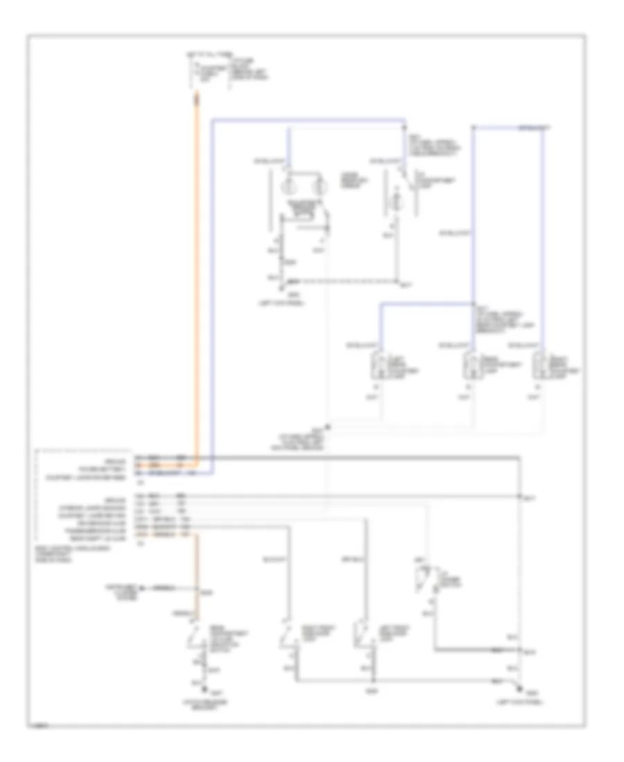
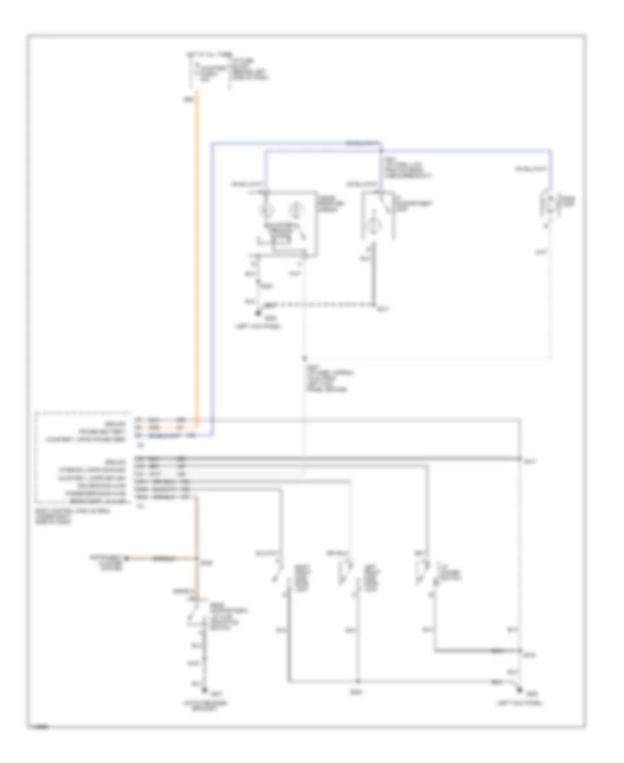
Instrument Illumination Wiring Diagram for Pontiac Firebird Trans Am 2001
List of elements for Instrument Illumination Wiring Diagram for Pontiac Firebird Trans Am 2001:
- (1999)
- (2000-01)
- (5 bulbs)
- (chevy) b g
- (cross car harn, approx 11 cm from inside rearview mirror breakout)
- (i/p harn, approx 17 cm from instrument cluster breakout) s224
- (pont)
- (pont) f c (chevy)
- A/t
- Ashtray lamp
- B11
- Courtesy lamps circuit
- Daytime running lamps (drl) module (mounted behind radio & hvac controls, left of glove box) (w/drl)
- Electronic traction control switch or second gear start switch
- Exterior lights system
- Fog lamp switch
- Folding top switch
- G130 (attached to rear of cylinder head) (v8 vin g)
- G134 (front of engine, bolted to pulley above a/c clutch connector) (v6 vin k)
- G200 (left kick panel)
- G407 (hatch release bracket)
- Gauges fuse 9 10a
- Head
- Headlight switch
- Hot at all times
- Hot in run, bulb test or start
- Hot with lamps on
- Hvac control
- I/p dimmer fuse 16 5a
- I/p dimmer switch
- I/p fuse block (behind left side of dash)
- Inflatable restraint steering wheel module coil
- Instrument cluster
- Left door illumination lamp
- M/t
- Max
- Min
- Nca
- Off
- Park
- Park lights relay
- Pnk
- Prndl illumination lamp
- Radio
- Radio (1999) steering wheel controls
- Right door illumination lamp
- S206
- S215
- S216
- S217
- S220
- S226 (i/p harn, approx 7 cm into headlamp switch breakout)
- S260 s260 (cross car harn, behind left side of dash)
- S470
- Solid state
- Stg whl cntrl fuse 13 1a
- Tail lts fuse 5 20a
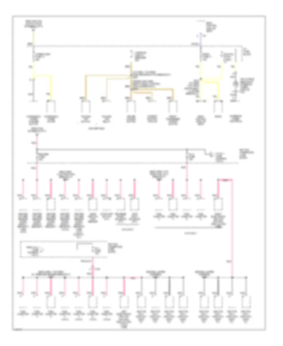
POWER DISTRIBUTION
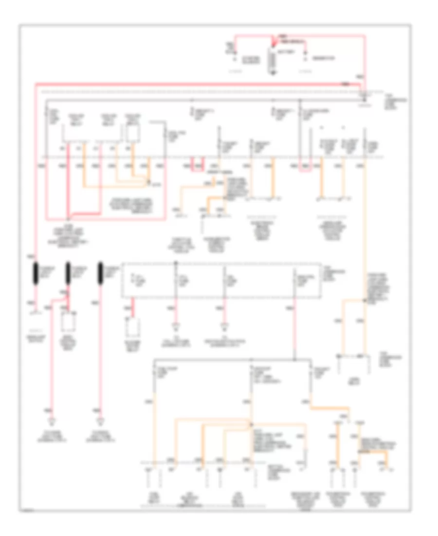
Power Distribution Wiring Diagram (1 of 4) for Pontiac Firebird Trans Am 2001
List of elements for Power Distribution Wiring Diagram (1 of 4) for Pontiac Firebird Trans Am 2001:
- (1999)
- (2000/2001)
- (eng harn, near powertrain control module) s106
- (forward lamp harn, 25 cm from underhood electrical center 1 breakout)
- (forward lamp harn, 4 cm from ign switch) breakout) s203
- (forward lamp harn, 8 cm from underhood electrical center 1 breakout) s168
- 30a
- A10
- Abs bat 1 fuse 40a
- Abs bat 2 fuse 50a
- Abs bat fuse 25a
- Accelerator & servo control module
- Air pump fuse 25a
- Air pump relay (vin g)
- Air solenoid relay (1999 w/vin g)
- Battery
- Blower motor relay
- Body control module (bcm)
- Bottom underhood fuse block
- Cool fan fuse 10a
- Cool fan fuse 40a
- Cooling fan 1 relay
- Cooling fan 2 relay
- Cooling fan 3 relay
- Electronic brake control module (ebcm)
- Eng ctrl fuse 50a
- Fuel pump fuse 20a
- Fuel pump relay
- Generator
- Headlamp opening door actuator control module
- Headlamp switch
- Hl door-horn fuse 50a
- Horn fuse 20a
- Horn relay
- I/p 1 fuse 40a
- I/p 2 fuse 40a
- Ign fuse 50a
- L hdlp door fuse 15a
- Nca
- Pcm bat fuse 10a
- Powertrain control module (pcm)
- R hdlp door fuse 15a
- Red
- S169 (forward lamp harn, 6 cm from underhood electrical center 1 breakout)
- S177 (forward lamp harn, 5 cm from underhood electrical center breakout)
- S179
- Secondary air injection (air) solenoid (2000/2001 vin g)
- Starter solenoid
- Tcs bat fuse 20a
- Throttle actuator control (tac) module
- To cigar accy fuse (diagram 3 of 4)
- To ignition switch pin b (diagram 2 of 4)
- To radio accy fuse (diagram 3 of 4)
- To tail lts fuse (diagram 3 of 4)
- Top underhood fuse block
- Vin g
- Vin k
Power Distribution Wiring Diagram (2 of 4) for Pontiac Firebird Trans Am 2001
List of elements for Power Distribution Wiring Diagram (2 of 4) for Pontiac Firebird Trans Am 2001:
- (1999) (2000-01)
- (chevy) b
- (eng harn, 7 cm from pcm breakout) s107
- (forward lamp harn, 11 cm from engine wiring harness junction block 1 breakout) s164
- (forward lamp harn, 15 cm from underhood electrical center 1 breakout) s182
- (forward lamp harn, 20 cm from underhood electrical center 1 breakout) s181
- (forward lamp harn, near left radiator support)
- (i/p harn, 2 cm from drl module breakout) s248
- (pont) a
- (vin g w/nw9)
- A/c compressor relay
- A/c cruise fuse 15a
- A/t
- Abs ign fuse 10a
- Acc
- Accelerator & servo control module (asm)
- Automatic transmission
- Back-up lamp switch (m/t)
- Body control module (bcm)
- Bottom underhood fuse block
- Bulb test
- C c
- C1 c4
- C101
- Clutch pedal position switch
- Clutch pedal positon (cpp) switch
- Cruise control module (vin g)
- Cruise control release switch
- Cruise control switches
- D10
- Daytime running lamps (drl) control module
- Electronic brake control module (ebcm)
- Electronic traction control switch (1999 w/vin g)
- Eng ctrl fuse 15a
- Etc fuse 10a
- Evaporative emission (evap) canister purge solenoid
- Evaporative emission (evap) canister vent solenoid
- From ign fuse (diagram 1 of 4)
- G109 (top right of radiator)
- Hvac control assembly
- Hvac control selector switch
- Hvac fuse 6 20a
- I/p fuse block
- Ignition control module (icm) (vin k)
- Ignition relay
- Ignition switch
- Instrument panel cluster
- Lock
- M/t
- Multifunction turn signal lever
- Nca
- Off
- Park/ neutral position switch
- Park/ neutral position switch (a/t)
- Pcm ign fuse 15a
- Pnk
- Powertrain control module (pcm)
- Powertrain control module (pcm) (vin k)
- Rear defogger switch
- Rear defogger timer/ relay
- Red
- Run
- S112
- S165 (forward lamp harn, 7 cm from underhood electrical center 2 breakout)
- S183 (forward lamp harn, 10 cm from engine wiring harness junction block 1 breakout)
- S185 (forward lamp harn, at engine wiring harness junction block 1 breakout)
- S254 (i/p harn, behind left side of dash)
- Second gear start switch (1999 chevy w/vin k)
- Start
- Strtr fuse 15a
- Throttle actuator control (tac) module (vin k)
- To air bag fuse (diagram 3 of 4)
- To eng sen fuse (diagram 4 of 4)
- To wiper/ wash fuse (diagram 4 of 4)
- Turn b/u fuse 2 20a
- Turn signal lamp flasher module
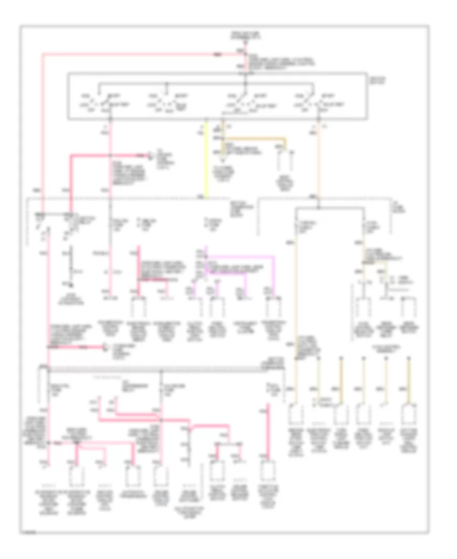
Power Distribution Wiring Diagram (3 of 4) for Pontiac Firebird Trans Am 2001
List of elements for Power Distribution Wiring Diagram (3 of 4) for Pontiac Firebird Trans Am 2001:
- (chev)
- (dash harn, at rear compt lid release relay breakout) s206
- (i/p harn, 7 cm from rear compt release breakout)
- (ip harn, 7 cm into ip fuse block breakout) s255
- (not used)
- (pont)
- (seat jumper harn, under driver's seat) s320
- A10
- Air bag fuse 10 15a
- Audio amplifier
- Auxiliary power outlet
- Body control module (bcm)
- Cigar accy fuse 11 25a
- Cigar lighter
- Convertible: (i/p harn, near g200 breakout)
- Courtesy fuse 8 20a
- Data link connector (dlc)
- Daytime running lamps control module
- Defog/seats circuit breaker 30a
- Driver's seat assembly
- E11
- E12
- From fusible link e (diagram 1 of 4)
- From fusible link f (diagram 1 of 4)
- From i/p 2 fuse (diagram 1 of 4)
- From s185 (diagram 2 of 4)
- G200 (left kick panel)
- Gauges fuse 9 10a
- Hazard flasher module
- Headlamp switch
- Hvac control assembly
- I/p fuse block
- Inflatable restraint sensing & diagnostic module (sdm)
- Instrument panel cluster
- Lumbar adjust switch
- Nca
- Outside rear view mirror switch
- Passenger's seat assembly
- Pnk
- Pontiac, w/ dual power seat
- Power seat cushion air control module
- Power seat inflator switch
- Power seat switch
- Pwr accy fuse 7 15a
- Radio
- Radio accy fuse 4 25a
- Radio power antenna
- Rear compt lid release relay
- Rear defogger timer/ relay
- Red
- Remote playback device cd player
- S211
- S217
- S333
- Shock sensor
- Stop/hazard fuse 1 20a
- Stoplamp switch
- Tail lts fuse 5 20a
- Theft deterrent relay
- Traction control switch (or second gear start switch) (2000-01)
- W/ single power seat
- W/ uz7, u59, w53, w54, w55
- W/ w53, u62 w/o uz7, w54, w55
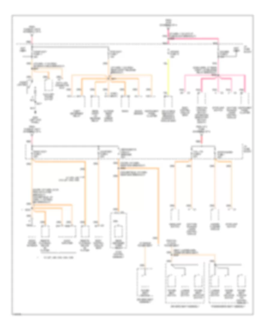
Power Distribution Wiring Diagram (4 of 4) for Pontiac Firebird Trans Am 2001
List of elements for Power Distribution Wiring Diagram (4 of 4) for Pontiac Firebird Trans Am 2001:
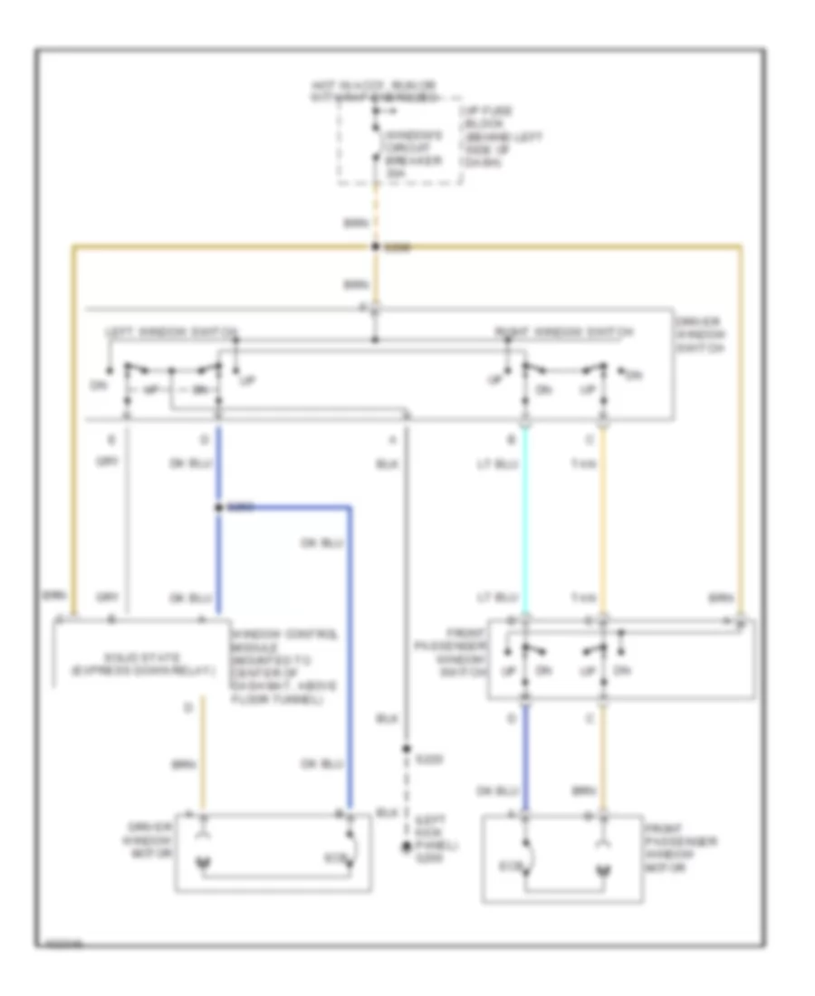
- (cross car harn, near window control module breakout) s208
- (eng harn, 14 cm from pcm breakout) s104
- (eng harn, 7 cm from oil presure sender breakout) s102
- (eng harn, 8 cm from fuel inj 4 breakout) s109
- (engine jumper harness) s122
- (engine jumper harness) s124
- (i/p harn, 7 cm from park brake switch breakout) s253
- Body control module (bcm)
- Bottom underhood fuse block
- C100
- Convertible
- Driver window switch
- Eng sen fuse 20a
- Folding top relay
- Folding top switch
- From ignition switch pin e (diagram 2 of 4)
- From inj 2 fuse h (diagram 4 of 4)
- From s164 (diagram 2 of 4)
- Front passenger window switch
- Fuel injector
- Fuel injector (vin g)
- Fuel injector (vin k)
- Heated oxygen sensor (ho2s) bank 1 sensor 1
- Heated oxygen sensor (ho2s) bank 1 sensor 2 (1999 vin g & 2000-01 all)
- Heated oxygen sensor (ho2s) bank 1 sensor 3 (1999 vin k)
- Heated oxygen sensor (ho2s) bank 2 sensor 1
- Heated oxygen sensor (ho2s) bank 2 sensor 2 (vin g)
- I/p fuse block
- Ignition coil/ module 1 (2000- 01)
- Ignition coil/ module 2 (2000- 01)
- Ignition coil/ module 3 (2000- 01)
- Ignition coil/ module 4 (2000- 01)
- Ignition coil/ module 5 (2000- 01)
- Ignition coil/ module 6 (2000- 01)
- Ignition coil/ module 7 (2000- 01)
- Ignition coil/ module 8 (2000- 01)
- Inflatable restraint steering wheel module coil
- Inj 1 fuse 15a
- Inj 2 fuse 15a
- Left electronic ignition control module (icm) (vin g) (1999)
- Mass airflow (maf) sensor
- Nca
- Pnk
- Radio
- Radio fuse 17 15a
- Reverse inhibit solenoid (m/t)
- Right electronic ignition control module (icm) (1999)
- S218 (i/p harn 4 cm from instrument cluster breakout)
- Skip shift solenoid (m/t)
- Steering wheel controls
- Stg whl cntrl fuse 3 1a
- Stoplamp switch (a/t)
- To inj 1 fuse (diagram 4 of 4)
- Vin g only
- Window control module
- Windows circuit breaker 30a
- Windshield wiper motor
- Windshield wiper/ washer switch
- Wiper/wash fuse 14 25a
POWER DOOR LOCKS
Power Door Lock Wiring Diagram for Pontiac Firebird Trans Am 2001
List of elements for Power Door Lock Wiring Diagram for Pontiac Firebird Trans Am 2001:
- (cross-car harness, 39cm from power window control module breakout) s267
- (cross-car harness,11cm from left power mirror control switch harness breakout) s504
- All doors lock
- Bat
- Body control module (bcm) (under right side of dash, near blower motor)
- Courtesy fuse 8 20a
- D11
- D12
- Driver door lock
- Driver door lock actuator
- Driver door lock switch
- Driver dr jamb sw
- Driver dr unlock
- Front passenger door lock
- Front passenger door lock actuator
- Front passenger door lock switch
- G200 (left kick panel)
- Ground
- Hot at all times
- I/p fuse block
- Interior lts feed
- Interior lights system
- Interior lts return
- Lock
- Lock input
- Pass dr jamb sw
- Pass dr unlock
- S217
- S220
- S268 (cross-car harn, 45cm from power window control module breakout)
- Tan
- Trunk rel rly ctrl
- Trunk rel sig
- Trunk/tailgate/ fuel doors system
- Unlock
- Unlock input
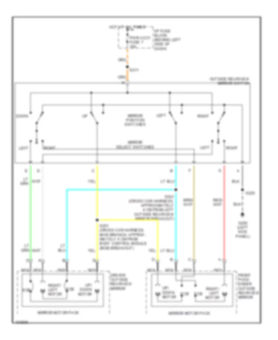
POWER MIRRORS
Power Mirror Wiring Diagram for Pontiac Firebird Trans Am 2001
List of elements for Power Mirror Wiring Diagram for Pontiac Firebird Trans Am 2001:
- Down
- Driver outside rearview mirror
- Ecb
- Front pass- enger outside rearview mirror
- G200 (left kick panel)
- Hot at all times
- I/p fuse block (behind left side of dash)
- Left
- Mirror motor pack
- Mirror position switches
- Mirror select switches
- Motor
- Nca
- Outside rearview mirror switch
- Pwr accy fuse 7 15a
- Right
- Right/ left motor
- S211
- S220
- S501 (cross car harness, approximately 4 cm from left outside rearview mirror breakout)
- Up/ down m
- Up/ down motor
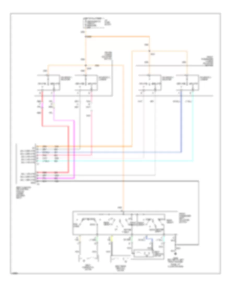
POWER SEATS
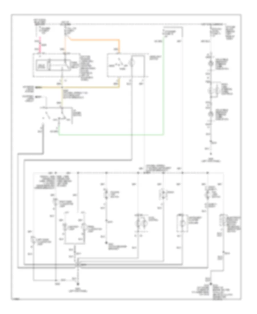
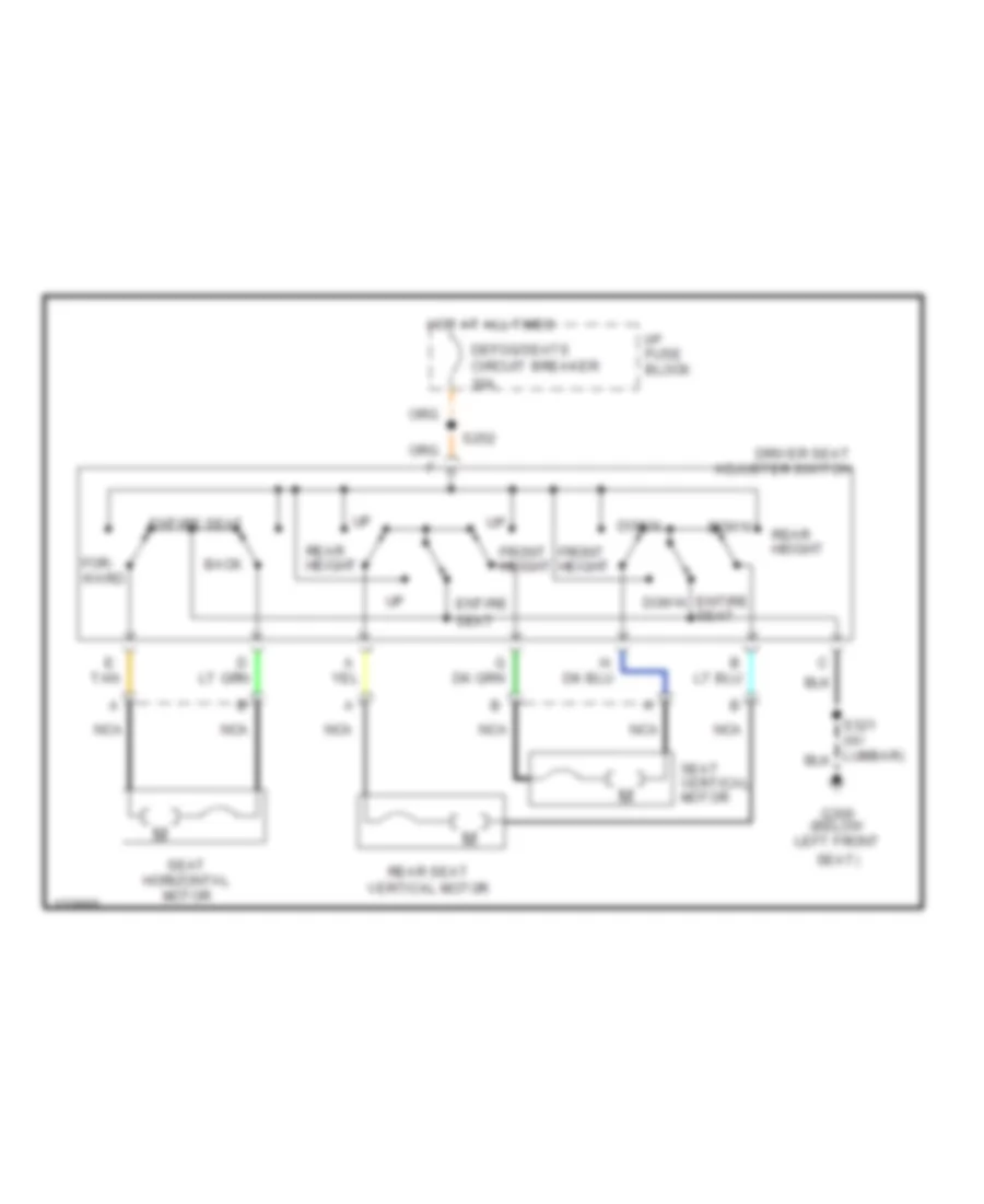
6-Way & Lumbar Power Seat Wiring Diagram for Pontiac Firebird Trans Am 2001
List of elements for 6-Way & Lumbar Power Seat Wiring Diagram for Pontiac Firebird Trans Am 2001:
- Back
- Deflate
- Defog/seats circuit breaker 30a
- Down
- Driver lumbar adjuster switch
- Entire seat
- For- ward
- Front height
- Front passenger lumbar adjuster switch
- Front passenger seat adjuster switch
- G tan
- G305 (bolted to left front rocker
- Gnd
- Hot at all times
- I/p fuse block
- Inflate
- Nca
- Panel at floor pan bar)
- Pnk
- Rear height
- Red
- S320
- S321
- S330
- S331
- Seat cushiion air control module (under driver's seat)
- Seat horizontal motor
- Seat rear vertical motor
- Seat vertical motor
- Sol 1 deflate
- Sol 1 inflate
- Sol 2 deflate
- Sol 2 inflate
- Sol 3 deflate
- Sol 3 inflate
- Sol 4 deflate
- Sol 4 inflate
- Solenoid 1 bolster
- Solenoid 2 lumbar
- Solenoid 3 bolster
- Solenoid 4 lumbar
6-Way Power Seat Wiring Diagram for Pontiac Firebird Trans Am 2001
List of elements for 6-Way Power Seat Wiring Diagram for Pontiac Firebird Trans Am 2001:
- Back
- Defog/seats circuit breaker 30a
- Down
- Driver seat adjuster switch
- E tan
- Entire seat
- For- ward
- Front height
- G300 (below left front
- Hot at all times
- I/p fuse block
- Nca
- Rear height
- Rear seat vertical motor
- S252
- Seat horizontal motor
- Seat vertical motor
- Seat)
POWER TOP/SUNROOF
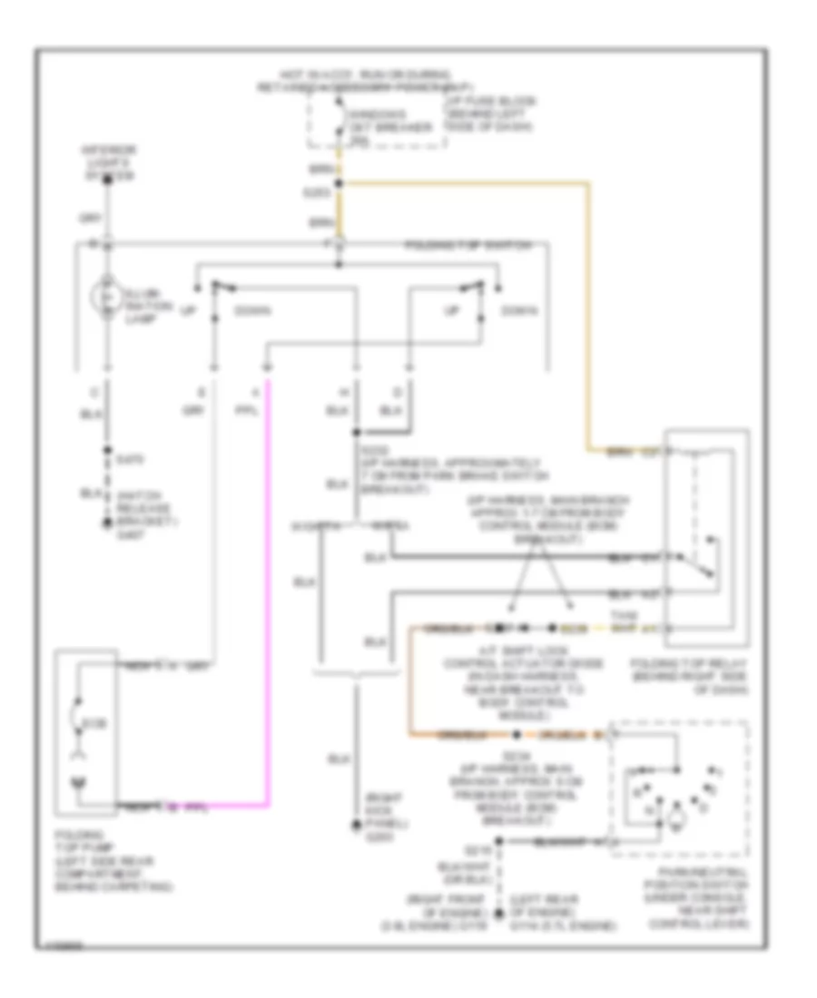
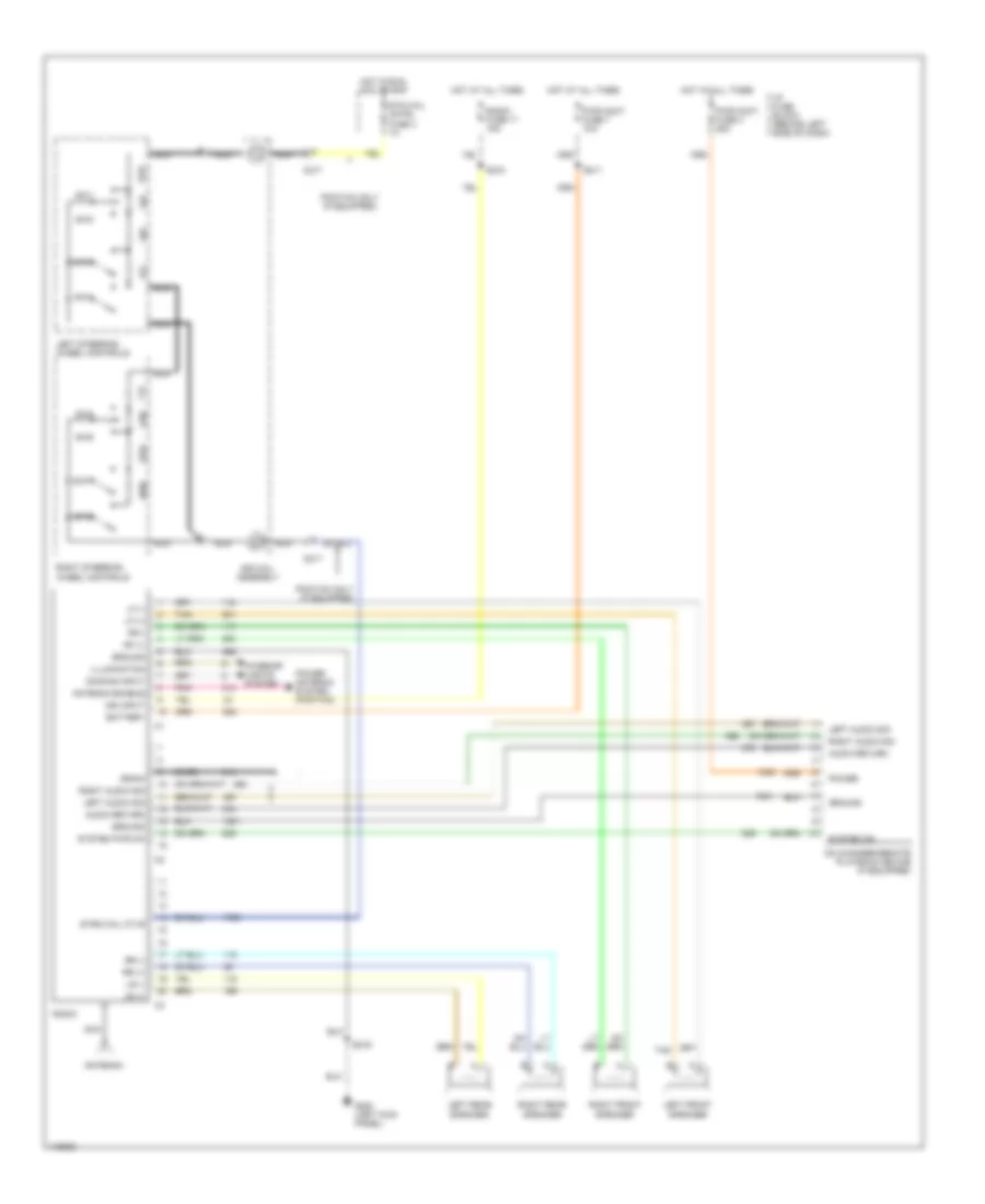
Power Top/Sunroof Wiring Diagrams for Pontiac Firebird Trans Am 2001
List of elements for Power Top/Sunroof Wiring Diagrams for Pontiac Firebird Trans Am 2001:
- (hatch release bracket) g407
- (i/p harness, main branch approx 1-7 cm from body control module (bcm) breakout)
- (left rear of engine) g114 (5.7l engine)
- (right front of engine) (3.8l engine) g119
- (right kick panel) g203
- A/t shift lock control actuator diode (in dash harness, near breakout to body control module)
- Down
- Ecb
- Folding top pump (left side rear compartment, behind carpeting)
- Folding top relay (behind right side of dash)
- Folding top switch
- Hot in accy, run or during retained accessory power (rap)
- I/p fuse block (behind left side of dash)
- Illum- ination lamp
- Interior lights system
- Nca
- Park/neutral position switch (under console, near shift control lever)
- S215
- S232 (i/p harness, approximately 7 cm from park brake switch breakout)
- S234 (i/p harness, main branch, approx 6 cm from body control module (bcm) breakout)
- S237
- S239
- S253
- S470
- W/eta
- W/o eta
- Windows ckt breaker 30a
POWER WINDOWS
Power Window Wiring Diagram for Pontiac Firebird Trans Am 2001
List of elements for Power Window Wiring Diagram for Pontiac Firebird Trans Am 2001:
- (left kick panel) g200
- Driver window motor
- Driver window switch
- Ecb
- Front passenger window motor
- Front passenger window switch
- Hot in accy, run or with rap energized
- I/p fuse block (behind left side of dash)
- Left window switch
- Right window switch
- S208
- S220
- S263
- Solid state (express down relay)
- Tan
- Window control module (mounted to center of dash mat, above floor tunnel)
- Windows circuit breaker 30a
RADIO
Radio Wiring Diagrams, with Amplifier for Pontiac Firebird Trans Am 2001
List of elements for Radio Wiring Diagrams, with Amplifier for Pontiac Firebird Trans Am 2001:
- (dash harn, near bcm breakout)
- (dash harn, near lr speaker breakout)
- (dash harn, near right kick panel ground) s307
- (dash harn, near rr speaker breakout)
- (dash harn, right dash)
- (or red)
- (or tan)
- 1998-01
- Antenna
- Antenna enable
- Audio amplifier (behind right rear quarter inner trim panel)
- Audio return
- Bare
- Batt
- Battery
- C217
- Cd changer-remote playback device (if equipped)
- Dimming input
- Drain
- E10
- E11
- E12
- E13
- E14
- E15
- E16
- F10
- F11
- F12
- F13
- F14
- F15
- F16
- G200 (left kick panel)
- Ground
- Hot at all times
- Hot in run, acc or rap
- I/p fuse block (behind left side of dash)
- Ign input
- Illumination
- Interior lights system
- Left audio sig
- Left front midrange speaker
- Left front tweeter speaker
- Left rear midrange speaker
- Left rear speaker subwoofer assembly
- Left rear tweeter speaker
- Left steering wheel controls
- Lf (+)
- Lf (-)
- Lr (+)
- Lr (-)
- Nca
- Pnk
- Power
- Power antenna system
- Pwr accy fuse 4 25a
- Pwr accy fuse 7 15a
- Radio
- Radio fuse 17 15a
- Red
- Rf (+)
- Rf (-)
- Rf(-)
- Right audio sig
- Right front midrange speaker
- Right front tweeter speaker
- Right rear midrange speaker
- Right rear speaker subwoofer assembly
- Right rear tweeter speaker
- Right steering wheel controls
- Rr (+)
- Rr (-)
- S211
- S216
- S217
- S218
- S300
- S301
- S302
- S303
- S304
- S305
- S306
- S333
- Sir coil assembly
- Stg whl cntrl fuse 3 1a
- Strg whl ctlr
- Sw1
- Sw2
- Sw3
- Sw4
- Sw5
- Sw6
- Sw7
- Sw8
- System on
- System pwr on
- Tan
Radio Wiring Diagrams, without Amplifier for Pontiac Firebird Trans Am 2001
List of elements for Radio Wiring Diagrams, without Amplifier for Pontiac Firebird Trans Am 2001:
- Antenna
- Antenna enable
- Audio return
- Bare
- Battery
- C217
- Cd changer-remote playback device (if equipped)
- Dimming input
- Drain
- G200 (left kick panel)
- Ground
- Hot at all times
- Hot in run, acc or rap
- I/p fuse block (behind left side of dash)
- Ign input
- Illumination
- Interior lights system
- Left audio sig
- Left front speaker
- Left rear speaker
- Left steering wheel controls
- Lf (+)
- Lf (-)
- Lr (+)
- Lr (-)
- Nca
- Pnk
- Pontiac only (if equipped)
- Power
- Power antenna system (pontiac)
- Pwr accy fuse 4 25a
- Pwr accy fuse 7 15a
- Radio
- Radio fuse 17 15a
- Rf (+)
- Rf(-)
- Right audio sig
- Right front speaker
- Right rear speaker
- Right steering wheel controls
- Rr (+)
- Rr (-)
- S211
- S216
- S218
- Sir coil assembly
- Stg whl cntrl fuse 3 1a
- Strg whl ctlr
- Sw1
- Sw2
- Sw3
- Sw4
- Sw5
- Sw6
- Sw7
- Sw8
- System on
- System pwr on
- Tan
SHIFT INTERLOCKS
Shift Interlock Wiring Diagram for Pontiac Firebird Trans Am 2001
List of elements for Shift Interlock Wiring Diagram for Pontiac Firebird Trans Am 2001:
- (1998)
- (1999-01)
- (3.8l)
- (i/p harn, approx 1 cm from bcm breakout)
- (i/p harn, approx 5 cm from bcm breakout) s234
- (i/p harn, approx 6 cm from bcm breakout)
- (opens w/ brake pedal depressed)
- (right front of engine) g119
- (sealed in harn, approx 6 cm from bcm breakout)
- A/t shift lock control actuator solenoid (in console, forward of shift control lever)
- Brake transmission shift interlock switch
- G114 (5.7l)
- Gauges fuse 9 10a
- Hatch release relay
- Hot in run, bulb test or start
- I/p fuse block
- Isolation diode (btsi) (1 amp)
- Park/neutral position switch (under console, near shift ctrl lever)
- Pnk
- Power tops
- Powertrain control module (pcm)
- S206
- S215
- S236
- S239
- Stoplamp/tcc switch assembly (mounted on brake pedal bracket)
STARTING/CHARGING
Charging Wiring Diagram for Pontiac Firebird Trans Am 2001
List of elements for Charging Wiring Diagram for Pontiac Firebird Trans Am 2001:
- (not used)
- 3.8l
- 5.7l
- Battery
- Battery junction block
- Engine wiring harness junction block 1 (in left front corner of engine compartment)
- G102 (left front shock tower)
- G120 (right side of engine block)
- Generator l
- Generator terminal l output
- Ground distribution system
- Powertrain control module (pcm) (in engine compartment, behind right strut tower)
- Red
- Starting/ charging system (starting circuit)
Starting Wiring Diagram for Pontiac Firebird Trans Am 2001
List of elements for Starting Wiring Diagram for Pontiac Firebird Trans Am 2001:
- (left front shock tower)
- (right side of engine block)
- 3.8l
- A/t
- Acc
- B5 crank signal
- Battery
- Battery junction block
- Body control module (bcm) (under right side of dash, near blower motor)
- Bulb test
- C11
- Clutch pedal position switch (on clutch pedal bracket)
- Crank signal
- Engine wiring harness junction block 2 (in left front corner of engine compartment)
- G102
- G120
- Generator
- Ign maxi fuse 50a
- Ignition switch
- Instrument cluster
- Lock
- M/t
- Off
- Park/neutral position switch (under console, near shift control lever)
- Powertrain control module (pcm) (in engine compartment, behind right strut tower)
- Red
- Run
- S170
- S183
- Start
- Starter motor
- Starter relay
- Starter relay control
- Starter solenoid
- Strtr minifuse 15a
- Underhood fuse block (in left front corner of engine compartment)
SUPPLEMENTAL RESTRAINTS
Supplemental Restraint Wiring Diagram for Pontiac Firebird Trans Am 2001
List of elements for Supplemental Restraint Wiring Diagram for Pontiac Firebird Trans Am 2001:
- (i/p harn, 18 cm from bcm breakout)
- (in i/p harness, at rear compartment lid release relay breakout)
- A10
- A11
- A12
- A13
- A14
- A15
- A16
- A17
- A18
- Air bag fuse 10 15a
- Air bag indicator
- Bar
- Body control module (bcm) (under right side of dash, near blower motor)
- C13
- Case ground
- Data link connector (dlc) (partial) (under dash to right of steering column)
- G200 (left kick panel)
- G302 (under center console)
- Gauges fuse 9 10a
- Ground
- High
- Hot in run, bulb test or start
- I/p fuse block (behind left side of dash)
- Ignition
- Inflatable restraint instrument panel module
- Inflatable restraint sensing & diagnostic module (sdm) (below rear of console)
- Inflatable restraint steering wheel module
- Inflatable restraint steering wheel module coil
- Instrument panel cluster (ipc)
- Low
- Nca
- Pnk
- S206
- S217
- S222
- Seat belt sig
- Seat belt swich
- Seat belt switch
- Serial data
- Shorting
- Shorting bar
- Solid state
- Star connector
TRANSMISSION
3.8L
3.8L VIN K, A/T Wiring Diagram for Pontiac Firebird Trans Am 2001
List of elements for 3.8L VIN K, A/T Wiring Diagram for Pontiac Firebird Trans Am 2001:
- 1-2 shift solenoid valve
- 1-2 ss valve ctrl
- 2-3 shift solenoid valve
- 2-3 ss valve ctrl
- 2nd gear ind ctrl
- 2nd gear start in
- 3-2 shift solenoid valve assembly
- 3-2 ss valve ctrl
- Automatic transmission (4l60-e)
- Automatic transmission fluid pressure manual valve position switch
- Batt (+)
- Brake sw sig in
- Class ii serial data
- Data link connector (partial) (under dash to right of steering column)
- Drl module, stoplamp switch, body control module
- Ect sens gnd
- Ect sens sig in
- Eng ctrl fuse 15a
- Eng sen fuse 20a
- Engine coolant temperature sensor (front of engine, below throttle body)
- Evap canister purge solenoid valve & electronic ignition control module
- Evap canister vent solenoid valve
- Fuel tank unit, a/c refrigerant pressure sensor
- G110 (front of engine, bolted to pulley above a/c clutch connector)
- Gages fuse 9 10a
- Hot at all times
- Hot in run or start
- Hot in run, bulb test or start
- I/p fuse block (behind left side of dash)
- Ign (run/start)
- Illumination lamp
- Instrument cluster
- Interior lights system
- Mass airflow sensor & heated oxygen sensors
- Mil ctrl
- Park/neutral position switch (near shift control lever)
- Pc sol valve hi
- Pc sol valve low
- Pcm bat fuse 10a
- Pcm gnd
- Pcm ign fuse 15a
- Pnk
- Pnp sw sig in
- Powertrain control module (pcm) (in engine compt, behind right strut tower)
- Pressure control solenoid valve
- Red
- Rev
- S101
- S104
- S107
- S110
- S121 (engine harn, 8 cm from pcm breakout)
- S182
- S206
- S215
- S234 (dash harn, 5 cm from bcm breakout)
- Second gear indicator
- Second gear start switch
- Sens gnd
- Service engine soon (mil) indicator
- Shift interlock system & hatch release circuit
- Splice pack sp200
- Stoplamp switch
- Tac serial data
- Tan
- Tcc pwm sol ctrl
- Tcc sol ctrl
- Tcc/shift interrupt switch
- Tft sens sig in
- Throttle actuator control module (on accel pedal bracket)
- Torque converter clutch pulse width modulation solenoid valve
- Torque converter clutch solenoid valve
- Trans range a in
- Trans range b in
- Trans range c in
- Transmission fluid temperature sensor
- Underhood fuse block (bottom) (left front corner of engine compt)
- Underhood fuse block (top) (left front corner of engine compt)
- Vehicle speed sensor (rear of transmission)
- Vss hi (signal)
- Vss lo (ground)
5.7L
5.7L VIN G, A/T Wiring Diagram for Pontiac Firebird Trans Am 2001
List of elements for 5.7L VIN G, A/T Wiring Diagram for Pontiac Firebird Trans Am 2001:
- 1-2 shift solenoid valve
- 1-2 ss valve
- 2-3 shift solenoid valve
- 2-3 ss valve
- 3-2 shift solenoid valve assembly
- 3-2 ss valve
- Anti-lock brakes system
- Automatic transmission (4l60-e)
- Automatic transmission fluid pressure manual valve position switch
- Batt (+)
- Body control module, brake malfunction indicator lamp, driver module, daytime running lights module & instrument cluster
- Brake sw in
- Data link connector (partial) (under dash to right of steering column)
- Ect sens gnd
- Ect sens in
- Eng ctrl fuse 15a
- Eng sens fuse 20a
- Engine coolant temperature sensor (left side of engine above generator)
- Evap canister purge solenoid valve
- Evap canister vent solenoid valve
- G110 (front of engine, bolted to pulley above a/c clutch connector)
- Gages fuse 9 10a
- Gnd
- Hot at all times
- Hot in run or start
- Hot in run, bulb test or start
- I/p fuse block (behind left side of dash)
- Ignition
- Instrument cluster
- Mass air- flow sensor, ho2 sensors
- Mil ctrl
- Park/neutral position switch (near shift control lever)
- Pc sol hi
- Pc sol low
- Pcm bat fuse 10a
- Pcm ign fuse 15a
- Pnk
- Pnp sw in
- Powertrain control module (pcm) (in engine compt, behind right strut tower)
- Pressure control solenoid valve
- Red
- Rev
- S104
- S106
- S107
- S110
- S116
- S116: eng harn, approx 9 cm from map sensor breakout
- S118
- S118: eng harn, approx 15 cm from map sensor breakout
- S119
- S119: eng harn, approx 9 cm from automatic transmission breakout
- S182
- S206
- S215
- S234 (dash harn, approx 5cm from bcm breakout)
- Sens gnd
- Serial data
- Service engine soon (mil) indicator
- Shift interlock system & hatch release circuit
- Splice pack sp200
- Stoplamp switch
- Tan
- Tcc pwm sol
- Tcc sol ctrl
- Tcc/shift interrupt switch
- Tft sens sig
- Throttle position sensor (on throttle body)
- Torque converter clutch pulse width modulation solenoid valve
- Torque converter clutch solenoid valve
- Tps 5v ref
- Tps gnd
- Tps sig in
- Transmission fluid temperature sensor
- Trs a
- Trs b
- Trs c
- Underhood fuse block (bottom) (left front corner of engine compt)
- Underhood fuse block (top) (left front corner of engine compt)
- Vehicle speed sensor (left rear of transmission)
- Vss hi (signal)
- Vss lo (ground)
5.7L VIN G, M/T Wiring Diagram for Pontiac Firebird Trans Am 2001
List of elements for 5.7L VIN G, M/T Wiring Diagram for Pontiac Firebird Trans Am 2001:
- Body control module, brake malfunction indicator lamp, driver module, daytime running lights module
- Clutch pedal position switch
- Cpp switch sens
- Data link connector (partial) (under dash to right of steering column)
- Eng sens fuse 20a
- G110 (front of engine, bolted to pulley above a/c clutch connector)
- Gages fuse 9 10a
- Hot in run or start
- Hot in run, bulb test or start
- I/p fuse block (behind left side of dash)
- Instrument cluster
- Manual transmission
- Mass airflow sensor, heated oxygen sensors
- Pnk
- Powertrain control module (pcm) (in engine compt, behind right strut tower)
- Reverse lockout
- Reverse lockout solenoid
- S104
- S206
- S215
- Serial data
- Ship shift indicator
- Skip shift
- Skip shift solenoid
- Splice pack sp200
- Underhood fuse block (bottom) (left front corner of engine compt)
- Vehicle speed sensor (left rear of transmission)
- Vss hi (signal)
- Vss lo (ground)
TRUNK, TAILGATE, FUEL DOOR
Trunk, Tailgate, Fuel Door Wiring Diagrams for Pontiac Firebird Trans Am 2001
List of elements for Trunk, Tailgate, Fuel Door Wiring Diagrams for Pontiac Firebird Trans Am 2001:
- A/t
- Battery
- Body control module (under right side of dash, near blower motor)
- Courtesy fuse 8 20a
- Daytime running lamps (drl) module (mounted behind radio & hvac controls, left of glove box)
- Engine controls system
- G114 (5.7l engine) (left rear of engine)
- G119 (3.8l engine) (right front of engine)
- G200 (left kick panel)
- G407 (hatch release bracket)
- Hot at all times
- I/p fuse block
- Instru- ment cluster system
- Isolation diode
- Lid release sig
- Lid rly ctrl
- M/t
- Nca
- Park brake switch
- Park/neutral position switch (under console near shift control lever)
- Pwr accy fuse 7 15a
- Rear compartment lid release actuator (in cargo compt)
- Rear compartment lid release relay (behind left side of dash)
- Rear compartment lid release switch
- S211
- S215
- S216
- S228 (i/p harn, main branch, approx 20 cm from rear compt lid release relay breakout)
- S234 (i/p harn, main branch, approx 5 cm from body control module breakout)
- S237 (in i/p harn, main branch, approx 6cm from bcm breakout)
- S239 (i/p harn, main branch, approx 1 cm from bcm breakout)
- S470
- Shift interlock system
WARNING SYSTEMS
Warning System Wiring Diagrams for Pontiac Firebird Trans Am 2001
List of elements for Warning System Wiring Diagrams for Pontiac Firebird Trans Am 2001:
- A13
- B11
- Battery (b+)
- Belt indic ctrl
- Body control module (bcm) (under right side of dash, near blower motor)
- Breakout)
- C13
- C14
- Courtesy fuse 8 20a
- D11
- D12
- D15
- Exterior lights system
- Fasten seat belt ind
- G200 (left kick panel)
- Gages fuse 9 10a
- Ground
- Head
- Headlamp switch
- Hot at all times
- Hot in run, bulb test or start
- I/p fuse block
- Ignition key warning switch (inside steering column)
- Ignition power
- Instrument cluster
- Key-in-ign in
- Left front side door lock
- Lft door sw in
- Lights on in
- Nca
- Off
- Park
- Pnk
- Right front side door lock
- Rt door sw in
- S206
- S216
- S217
- S220
- S226 (i/p harn, in headlamp switch breakout)
- Seat belt switch (in driver's seat belt buckle)
- Seat blt sw in
WIPER/WASHER
Wiper/Washer Wiring Diagram for Pontiac Firebird Trans Am 2001
List of elements for Wiper/Washer Wiring Diagram for Pontiac Firebird Trans Am 2001:
- (ptc)
- 24k
- End of sweep switch
- G108 (top left of radiator support)
- High
- Hot in accy & run
- I/p fuse block (behind left side of dash)
- Low
- Low speed relay
- Mist
- Nca
- Off
- Park relay
- Park switch
- Pnk
- Pulse
- Red
- S155
- Washer switch
- Wind- shield washer pump (fwrd of rad suppt)
- Wind- shield wiper motor
- Wiper/ wash fuse 14 25a
- Wiper/ washer switch
- Wipers isolation diode (3a)

 Dansk
Dansk Deutsch
 Ελληνικά
 English
 English
 Español
 Suomi
Suomi Français
 Français
 עברית
עברית Hrvatski
 Magyar
 Italiano
 日本語
日本語 한국어
한국어 Nederlands
 Polski
 Português
 Português
 Română
 Русский
 Slovenčina
 Slovenščina
 Svenska
 Türkçe
 中文 (中国)