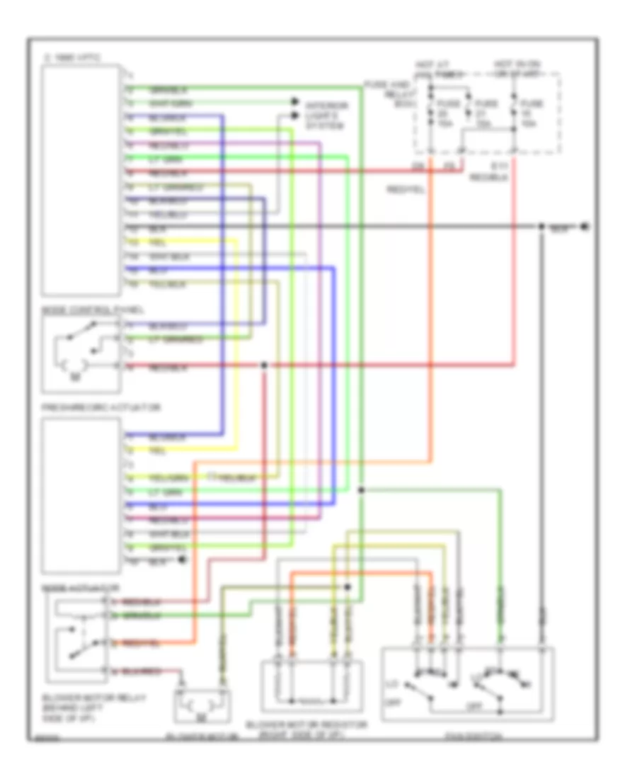
AIR CONDITIONING
A/C Wiring Diagram for Subaru Legacy Brighton 1997
 https://portal-diagnostov.com/license.html
Automotive Electricians Portal FZCO
Automotive Electricians Portal FZCO
https://portal-diagnostov.com/license.html
https://portal-diagnostov.com/license.html
Automotive Electricians Portal FZCO
Automotive Electricians Portal FZCO
List of elements for A/C Wiring Diagram for Subaru Legacy Brighton 1997:
- (behind left side of i/p)
- (center of i/p)
- (right side of engine)
- A/c switch
- Acc
- Air conditioner relay (in air conditioner relay holder)
- Air conditioner relay holder
- Blower motor
- Blower motor relay (behind left side of i/p)
- Blower motor resistor (behind right side of i/p)
- C 1995 vftc
- Compressor
- Control module
- Diode (a/c) (rear of left front fender)
- E11
- Engine
- Evaporation thermoswitch
- F27
- Fan switch
- Fresh/recirc actuator
- Fuse 10a
- Fuse 15a
- Fuse 20a
- Fuse and relay box
- Hot at all times
- Hot in on or start
- Ignition switch
- Interior lights system
- Lock
- Main fan motor
- Main fan relay 1 (in air conditioner relay holder)
- Main fan relay 2 (in air conditioner relay holder)
- Mode actuator
- Mode control panel
- Off
- Pressure switch
- Run
- Start
- Sub fan motor
- Sub fan relay
- Sub fan relay 2 (in air conditioner relay holder)
Heater Wiring Diagram for Subaru Legacy Brighton 1997
List of elements for Heater Wiring Diagram for Subaru Legacy Brighton 1997:
- (right side of i/p)
- Blower motor
- Blower motor relay (behind left side of i/p)
- Blower motor resistor
- Box
- C 1995 vftc
- E11
- Fan switch
- Fresh/recirc actuator
- Fuse 10a
- Fuse 15a
- Fuse and
- Hot at all times
- Hot in on or start
- Interior lights system
- Mode actuator
- Mode control panel
- Off
- Relay
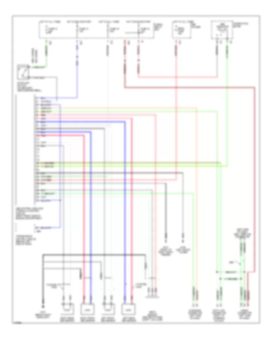
ANTI-LOCK BRAKES
Anti-lock Brake Wiring Diagrams for Subaru Legacy Brighton 1997
List of elements for Anti-lock Brake Wiring Diagrams for Subaru Legacy Brighton 1997:
- (left side of dash) obd ii service connector
- (w/o cruise)
- Abs control module & hydraulic control module (right front side of engine compartment)
- Abs g sensor (center of pass compt, on floor)
- Abs indicator
- B51
- B52
- B56
- Check connector (left side of dash)
- Combination meter
- Data link connector (right of steering column)
- Diagnosis connector (left side of dash)
- F34
- F42
- Fuse & relay box
- Fuse 12 20a
- Fuse 15 10a
- Fuse 18 10a
- Fuse 19 20a
- G101 (front of right front fender)
- G102 (left shock tower)
- G107 (behind right headlight)
- Hot at all times
- Hot in run or start
- I14
- Left front abs sensor
- Left rear abs sensor
- Nca
- Pnk
- Red
- Right front abs sensor
- Right rear abs sensor
- Sbf holder
- Sbf-6 fuse 45a
- Stoplight switch (on bracket, above brake pedal)
- Transmission control module (behind left side of dash)
- Twisted pair
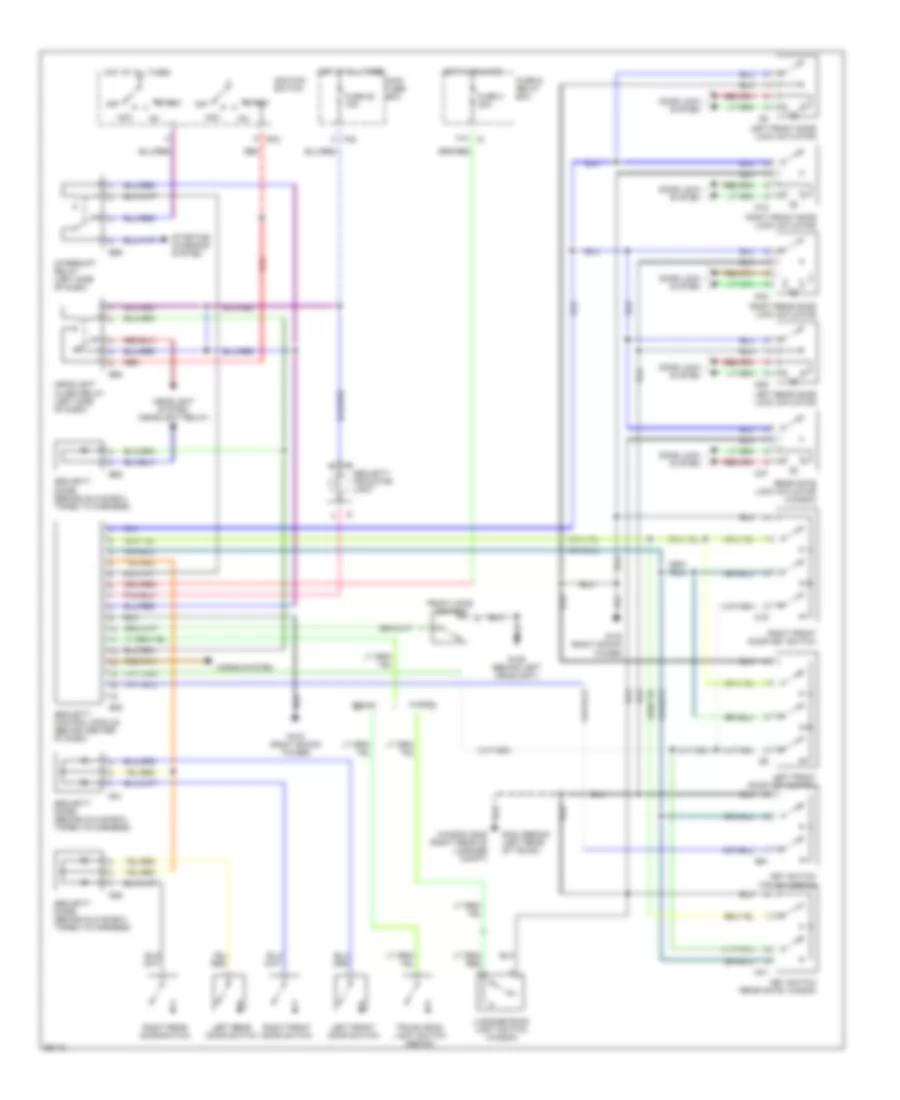
ANTI-THEFT
Anti-theft Wiring Diagram for Subaru Legacy Brighton 1997
List of elements for Anti-theft Wiring Diagram for Subaru Legacy Brighton 1997:
- (wagon) g405 (right rear of luggage compt)
- Acc
- B39
- B58
- B59
- B72
- B89
- D18
- D19
- D26
- D32
- D41
- D47
- Door lock system
- F13
- F35
- Front hood switch
- Fuse & relay box
- Fuse 25 15a
- Fuse 3 20a
- G103 (right shock tower)
- G106 (behind left headlight)
- G404 (sedan) (left rear of trunk)
- Headlight alarm relay (left side of dash)
- Headlight system (headlight relay)
- Horns system
- Hot at all times
- Hot in on & acc
- Ignition switch
- Interrupt relay (left side of dash)
- Key switch (rear gate, wagon)
- Key switch (trunk, sedan)
- Left front door key switch
- Left front door lock actuator
- Left front door switch
- Left rear door lock actuator
- Left rear door switch
- Luggage room light switch (wagon)
- Main fuse box
- Off
- R29
- R31
- R61
- Rear gate lock actuator (wagon)
- Red
- Right front door key switch
- Right front door lock actuator
- Right front door switch
- Right rear door lock actuator
- Right rear door switch
- Security control module (behind center of dash)
- Security diode (behind glove box, taped to harness)
- Security indicator light
- Sedan
- Start
- Starting/ charging system
- Trunk room light switch (sedan)
- Wagon
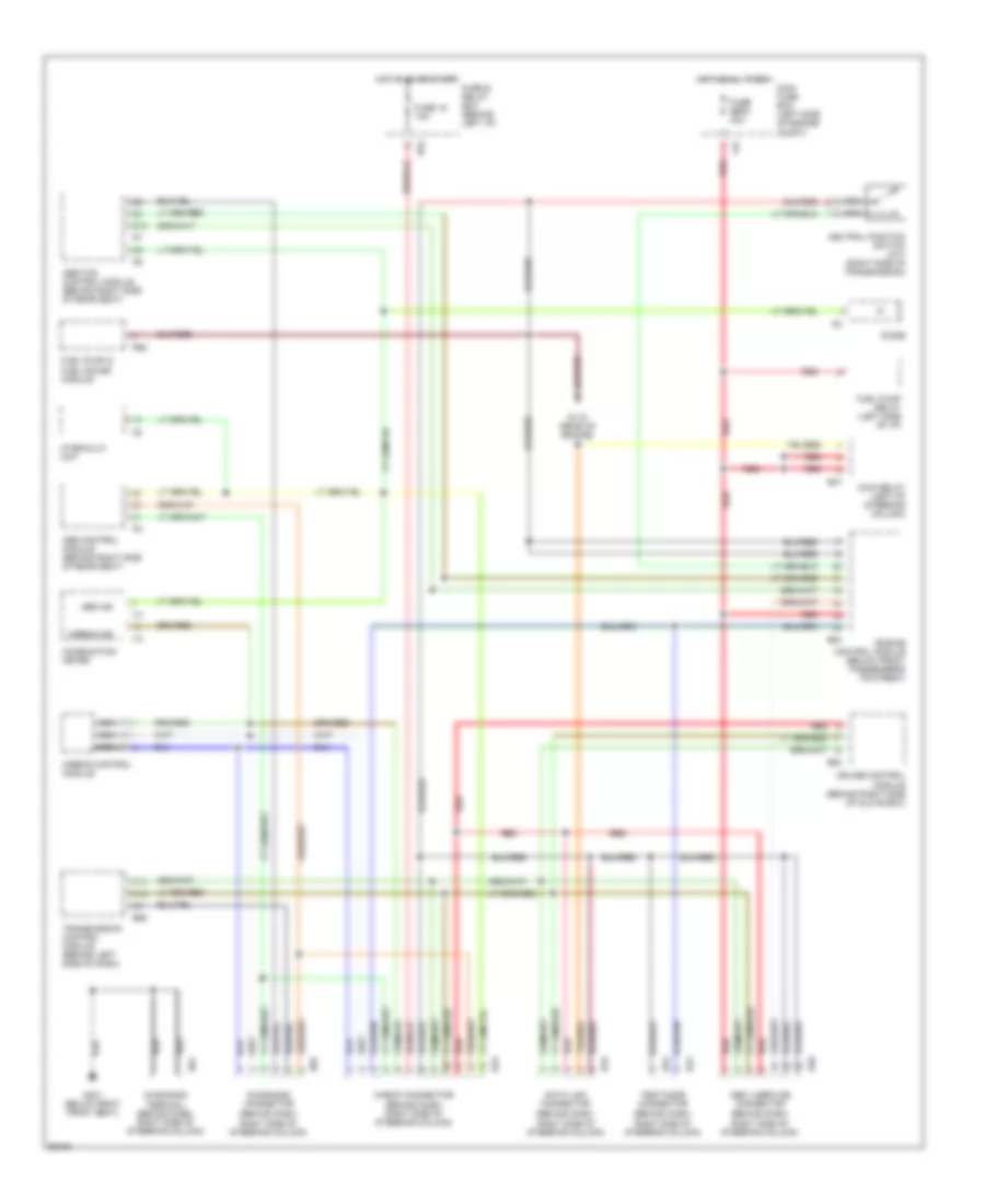
COMPUTER DATA LINES
Computer Data Lines for Subaru Legacy Brighton 1997
List of elements for Computer Data Lines for Subaru Legacy Brighton 1997:
- (behind dash, right side of steering column)
- Abs control module (behind right side of rear seat)
- Abs ind
- Abs/tcs control module (behind right side of rear seat)
- Airbag control module
- Airbag ind
- B40
- B47
- B52
- B56
- B75
- B76
- B78
- B79
- B81
- B82
- B84
- B94
- C12
- C13
- Check connector (behind dash, right side of steering column)
- Combination meter
- Cruise control module (behind right side of glove box)
- D19
- Data link connector
- Diagnosis connector
- Diagnosis terminal (behind dash, right side of steering column)
- Diode
- Engine control module (below front passenger's footrest)
- F37
- Fuel pump & fuel gauge module
- Fuel pump relay (left side of i/p)
- Fuse & relay box (behind left i/p)
- Fuse 15 10a
- Fuse sbf2 30a
- G115 (rear of engine)
- G301 (below right front seat)
- Hot at all times
- Hot in on or start
- Hydraulic unit
- I12
- I14
- Main fuse box (left side of engine compt)
- Main relay (left of steering column)
- Nca
- Neutral position switch (m/t) (right side of transmission)
- Obd ii service connector
- R58
- Red
- Test mode connector
- Transmission control module (behind left side of dash)
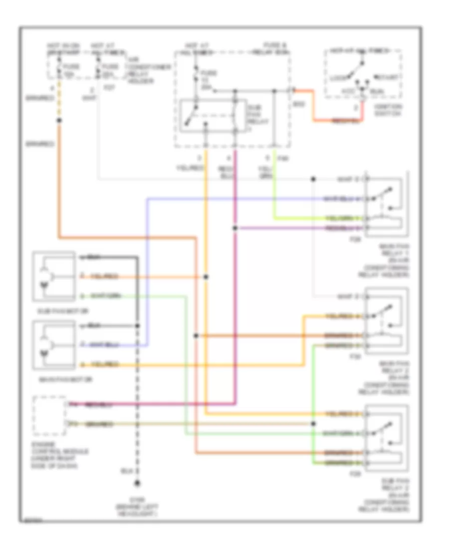
COOLING FAN
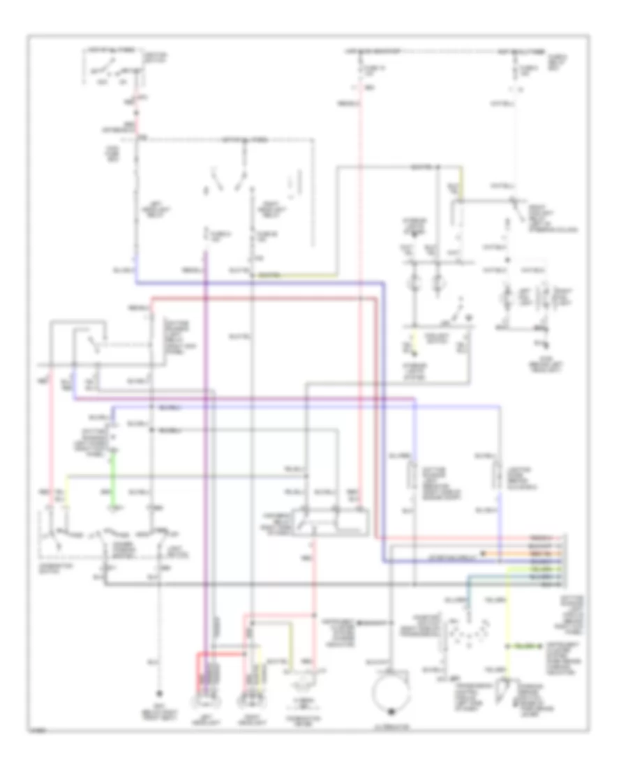
Cooling Fan Wiring Diagram, with A/C for Subaru Legacy Brighton 1997
List of elements for Cooling Fan Wiring Diagram, with A/C for Subaru Legacy Brighton 1997:
- Acc
- Air conditioner relay holder
- All times
- B52
- Engine control module (under right side of dash)
- F27
- F28
- F29
- F30
- F40
- Fuse &
- Fuse 10a
- Fuse 20a
- G106 (behind left headlight)
- Hot at
- Hot at all times
- Hot in on or start
- Ignition switch
- Lock
- Main fan motor
- Main fan relay 1 (in air conditioning relay holder)
- Main fan relay 2 (in air conditioning relay holder)
- Relay box
- Run
- Start
- Sub fan motor
- Sub fan relay
- Sub fan relay 2 (in air conditioning relay holder)
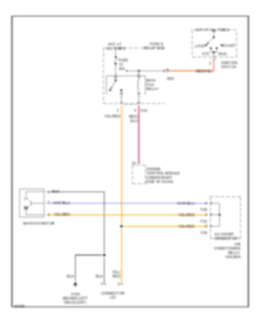
Cooling Fan Wiring Diagram, without A/C for Subaru Legacy Brighton 1997
List of elements for Cooling Fan Wiring Diagram, without A/C for Subaru Legacy Brighton 1997:
- A/c short connector
- Acc
- Air conditioning relay holder
- All times
- B52
- Connector lid
- Engine control module (under right side of dash)
- F28
- F29
- F30
- F40
- Fuse &
- Fuse 20a
- G106 (behind left headlight)
- Hot at
- Hot at all times
- Ignition switch
- Lock
- Main fan motor
- Main fan relay
- Relay box
- Run
- Start
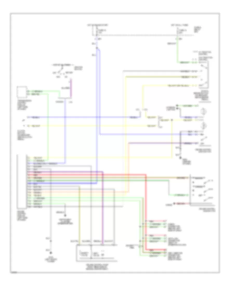
CRUISE CONTROL
Cruise Control Wiring Diagram for Subaru Legacy Brighton 1997
List of elements for Cruise Control Wiring Diagram for Subaru Legacy Brighton 1997:
- (except 1995)
- A/t
- Acc
- B51
- Canada
- Cancel
- Check connector (behind left side of dash)
- Clutch switch (on bracket, above clutch pedal)
- Cruise control
- Cruise control module (left side of dash)
- Cruise control pump (right rear side of engine compartment)
- Data link connector (right of steering column)
- Fuse & relay box
- Fuse 12 20a
- Fuse 18 10a
- G102 (left shock tower)
- G202 (center of dash)
- Horns
- Hot at all times
- Hot in on and start
- Ignition switch
- Instrument cluster (speedometer)
- Interior lighting
- M/t
- Main switch
- Obd ii service connector (behind left side of dash)
- Off
- Red
- Resume
- Safety valve
- Set
- Start
- Stop & brake switch (on bracket, above brake pedal)
- Sub switch
- Transmission control module (left side of dash)
- U.s.
- Vent valve
- W/ traction control
- W/o traction control
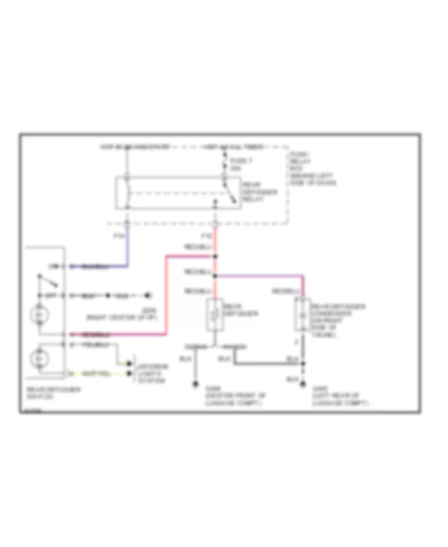
DEFOGGERS
Defogger Wiring Diagram for Subaru Legacy Brighton 1997
List of elements for Defogger Wiring Diagram for Subaru Legacy Brighton 1997:
- F12
- F14
- Fuse 7 20a
- Fuse/ relay box (behind left side of dash)
- G206 (right center of i/p)
- G405 (left rear of luggage compt)
- G408 (center front of luggage compt)
- Hot at all times
- Hot in on and start
- Interior lights system
- Off
- Rear defogger
- Rear defogger condenser (on right side of trunk)
- Rear defogger relay
- Rear defogger switch
- Sedan
- Wagon
ENGINE PERFORMANCE
2.2L
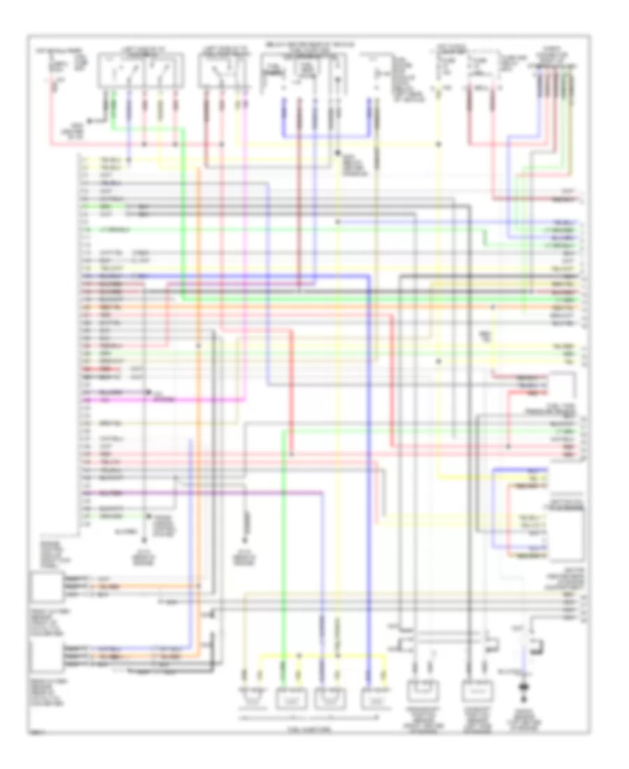
2.2L, Engine Performance Wiring Diagrams (1 of 2) for Subaru Legacy Brighton 1997
List of elements for 2.2L, Engine Performance Wiring Diagrams (1 of 2) for Subaru Legacy Brighton 1997:
- (below center rear of vehicle) fuel pump and fuel gauge module)
- (left side of i/p) fuel pump relay
- (left side of i/p) main relay
- A/c system
- B52
- Camshaft position sensor (left side of engine)
- Check connector (right of steering column)
- Crankshaft position sensor (front center of engine)
- Engine control module (right kick panel)
- F37
- F40
- Front oxygen sensor (front of catalytic converter)
- Fuel gauge
- Fuel gauge sub module (awd) (below left rear of vehicle)
- Fuel injectors
- Fuel temp gauge
- Fuse 10a
- Fuse 15a
- Fuse and relay box
- G115 (rear of engine)
- G202 (center of i/p)
- G302 (below center console)
- Hot at all times
- Hot in run
- Ignition coil (top of engine)
- Ignitor (center rear of engine compartment)
- Knock sensor (top center of engine)
- Main fuse box
- Nca
- Or start
- Rear oxygen sensor (rear of catalytic converter)
- Red
- Sbf-2 30a
- Trans- mission control system
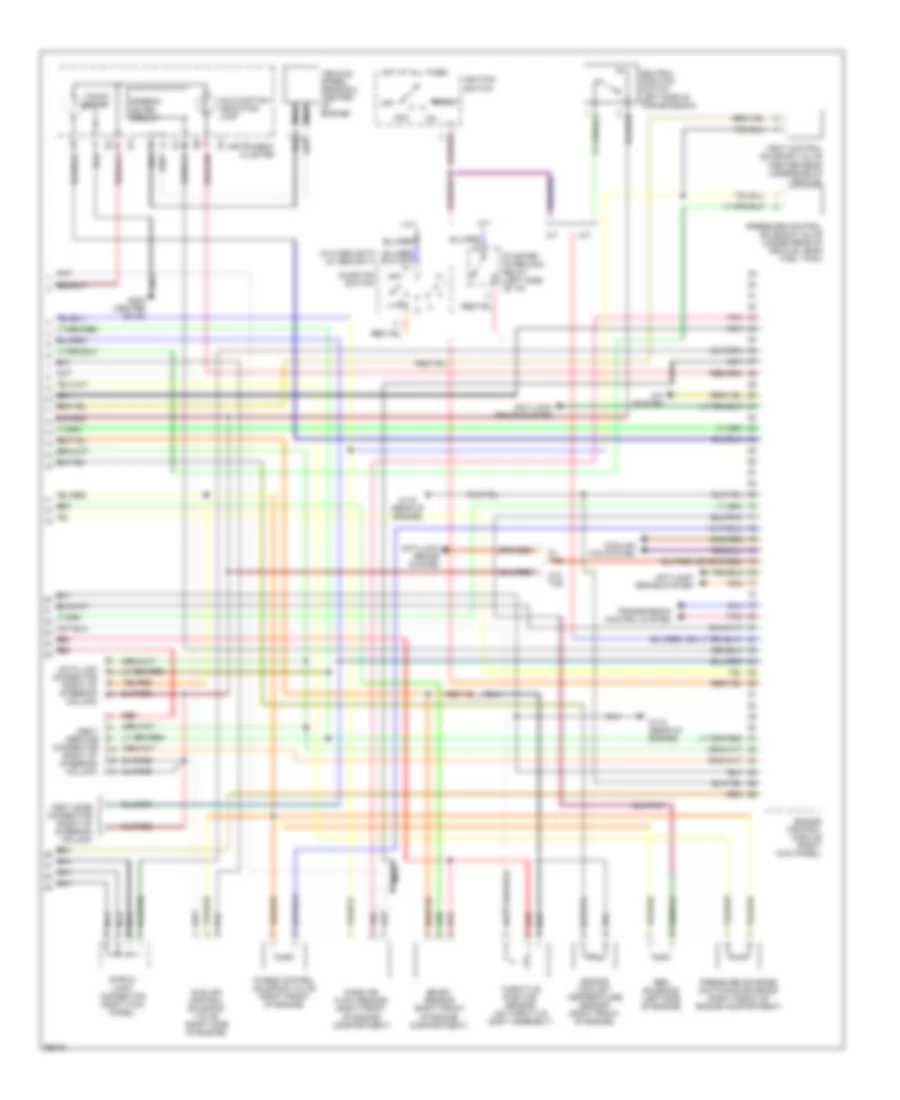
2.2L, Engine Performance Wiring Diagrams (2 of 2) for Subaru Legacy Brighton 1997
List of elements for 2.2L, Engine Performance Wiring Diagrams (2 of 2) for Subaru Legacy Brighton 1997:
- (right front of engine compartment)
- (w/o security) (w/ security)
- A/c system
- A/t
- Acc
- Anti-lock brake system
- Boost sensor
- Cooling fan system
- Data link connector (right of steering column)
- Egr solenoid (left side of engine)
- Engine control module (right kick panel)
- Engine coolant temperature sensor (right front of engine)
- G115 (rear of engine)
- G202 (center of i/p)
- Hot at all times
- I10
- I11
- I12
- I14
- Idle air control solenoid valve (right side of engine)
- Ignition switch
- Inhibitor switch
- Instrument cluster
- M/t
- Malfunction indicator lamp
- Mass air flow sensor
- Nca
- Neutral position switch (left side of transmission)
- Obd-ii service connector (right of steering column)
- Off
- Pnk
- Pressure control solenoid valve (under rear of vehicle, near fuel tank)
- Pressure sources switching solenoid (right front of engine compartment)
- Purge control solenoid valve (right front of engine)
- Red
- Shield joint connector (right kick panel)
- Speedo- meter circuit
- Start
- Starter interlock relay (left side of i/p)
- Tacho- meter
- Test mode connector (right of steering column)
- Throttle position sensor (on throttle body assembly)
- Transmission control system
- Vehicle speed sensor 2 (center of engine)
- Vent control solenoid valve (center rear underside of vehicle)
- W/ tcs
- W/o tcs
2.5L
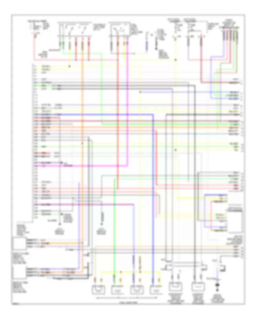
2.5L, Engine Performance Wiring Diagrams (1 of 2) for Subaru Legacy Brighton 1997
List of elements for 2.5L, Engine Performance Wiring Diagrams (1 of 2) for Subaru Legacy Brighton 1997:
- A/c system
- B52
- Camshaft position sensor (left side of engine)
- Check connector (right of steering column)
- Crankshaft position sensor (front center of engine)
- Engine control module (right kick panel)
- F37
- F40
- Front oxygen sensor (front of catalytic converter)
- Fuel injectors
- Fuel pump (top of fuel tank)
- Fuel pump relay (left side of i/p)
- Fuse 10a
- Fuse 15a
- Fuse and relay box
- G115 (rear of engine)
- G202 (center of i/p)
- G302 (below center console)
- Hot at all times
- Hot in run
- Ignition coil (top of engine)
- Ignitor (center rear of engine compartment)
- Knock sensor (top center of engine)
- Main fuse box
- Main relay (left side of i/p)
- Nca
- Or start
- Rear oxygen sensor (rear of catalytic converter)
- Red
- Sbf-2 30a
- Trans- mission control system
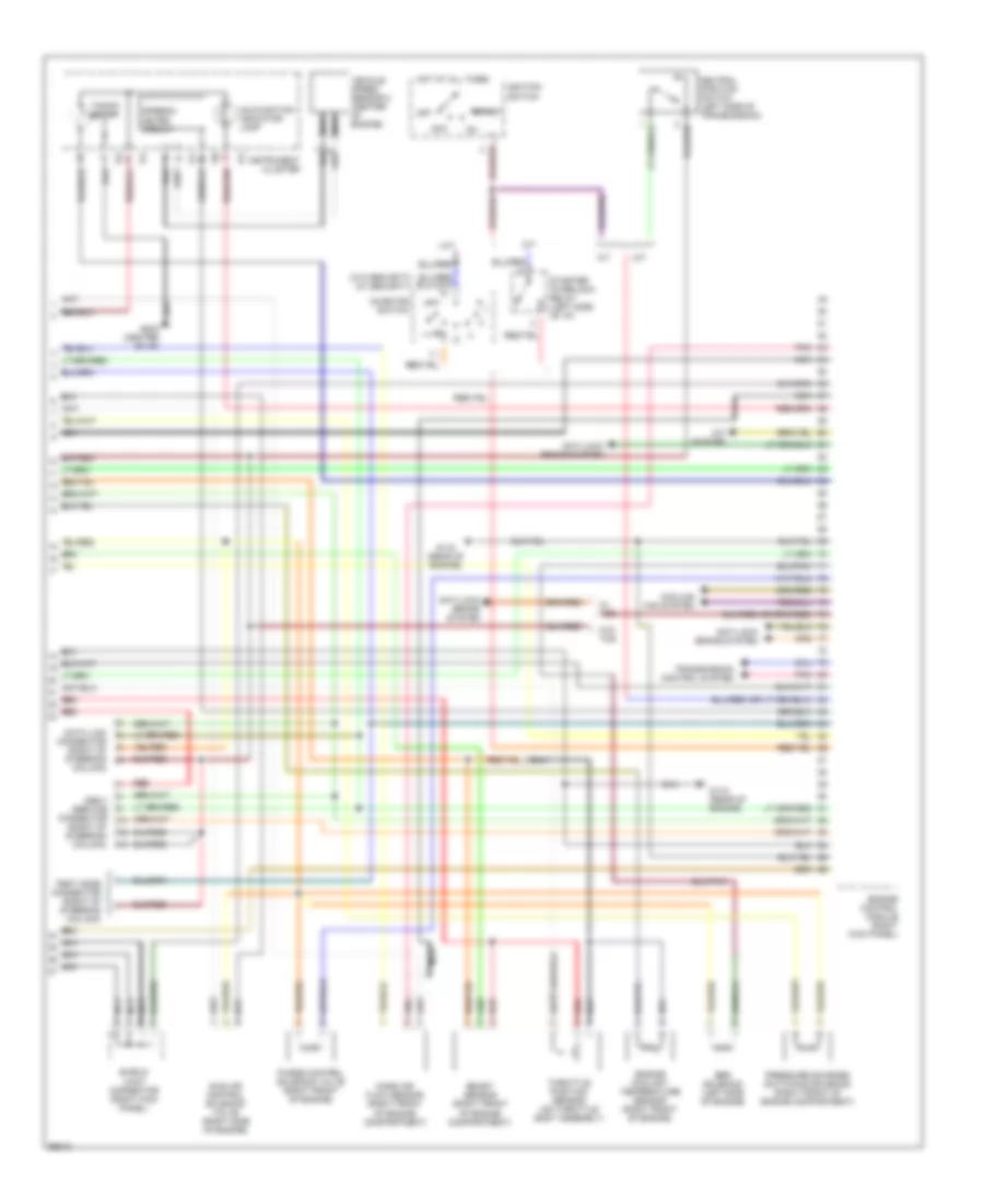
2.5L, Engine Performance Wiring Diagrams (2 of 2) for Subaru Legacy Brighton 1997
List of elements for 2.5L, Engine Performance Wiring Diagrams (2 of 2) for Subaru Legacy Brighton 1997:
- (right front of engine compartment)
- (w/o security) (w/ security)
- A/c system
- A/t
- Acc
- Anti-lock brake system
- Boost sensor
- Cooling fan system
- Data link connector (right of steering column)
- Egr solenoid (left side of engine)
- Engine control module (right kick panel)
- Engine coolant temperature sensor (right front of engine)
- G115 (rear of engine)
- G202 (center of i/p)
- Hot at all times
- I10
- I11
- I12
- I14
- Idle air control solenoid valve (right side of engine)
- Ignition switch
- Inhibitor switch
- Instrument cluster
- M/t
- Malfunction indicator lamp
- Mass air flow sensor
- Nca
- Neutral position switch (left side of transmission)
- Obd-ii service connector (right of steering column)
- Off
- Pnk
- Pressure sources switching solenoid (right front of engine compartment)
- Purge control solenoid valve (right front of engine)
- Red
- Shield joint connector (right kick panel)
- Speedo- meter circuit
- Start
- Starter interlock relay (left side of i/p)
- Tacho- meter
- Test mode connector (right of steering column)
- Throttle position sensor (on throttle body assembly)
- Transmission control system
- Vehicle speed sensor 2 (center of engine)
- W/ tcs
- W/o tcs
EXTERIOR LIGHTS
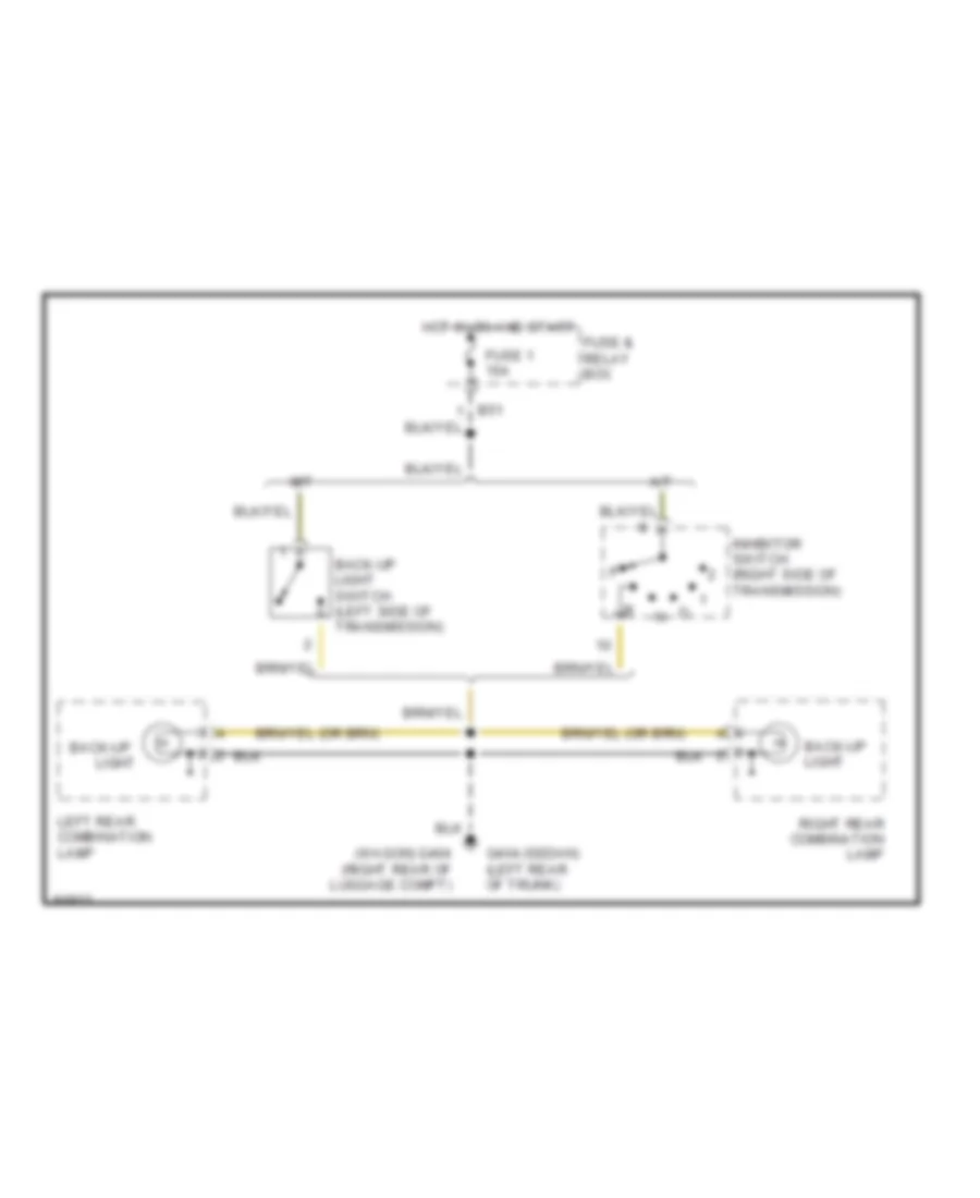
Back-up Lamps Wiring Diagram for Subaru Legacy Brighton 1997
List of elements for Back-up Lamps Wiring Diagram for Subaru Legacy Brighton 1997:
- (wagon) g404 (right rear of luggage compt)
- A/t
- Back-up
- Back-up light
- Back-up light switch (left side of transmission)
- Fuse & relay box
- Fuse 1 15a
- G404 (sedan) (left rear of trunk)
- Hot in on and start
- Inhibitor switch (right side of transmission)
- Left rear combination lamp
- Light
- M/t
- Right rear combination lamp
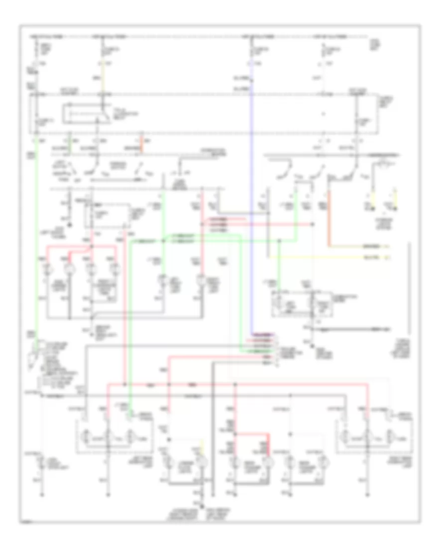
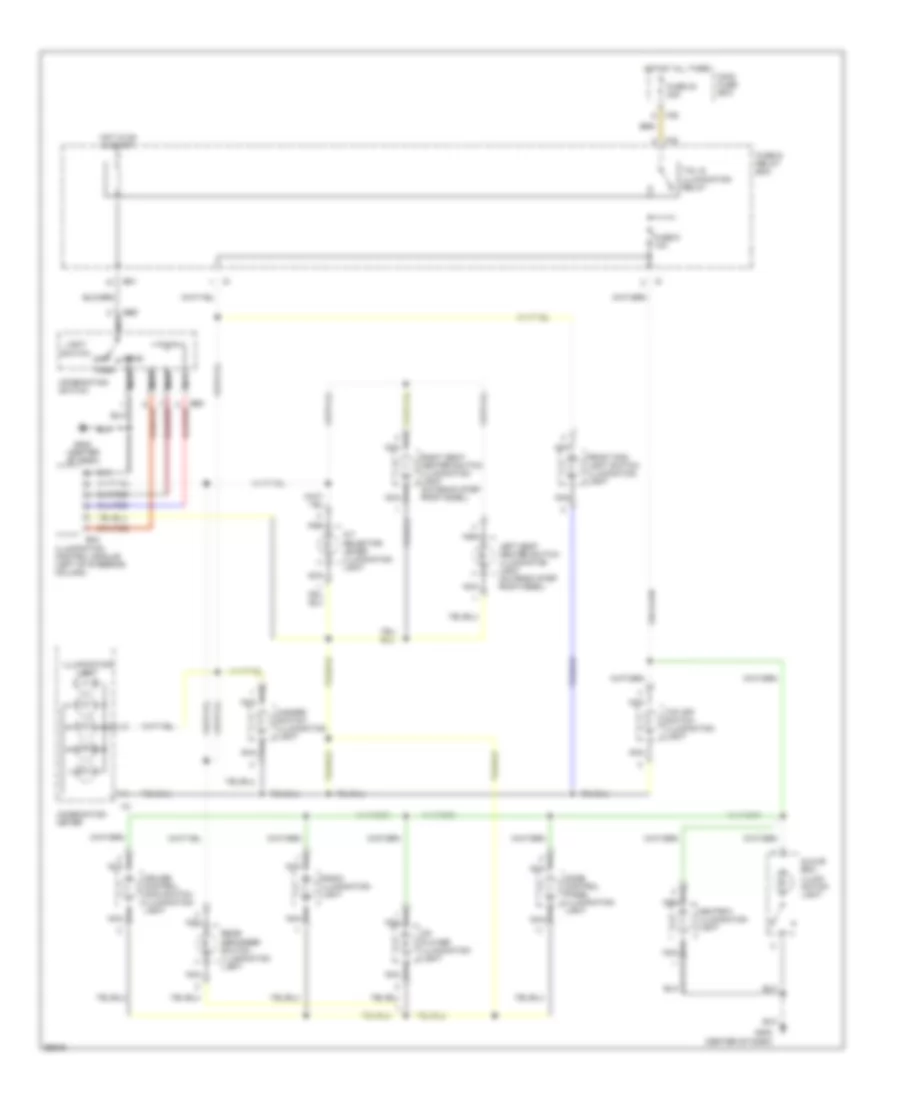
Exterior Lamps Wiring Diagram for Subaru Legacy Brighton 1997
List of elements for Exterior Lamps Wiring Diagram for Subaru Legacy Brighton 1997:
- (1996-99)
- (behind right headlight) g107
- (left shock
- (wagon) g405 (right rear of luggage compt)
- B51
- B52
- Combination
- Combination meter
- F35
- F36
- F37
- F40
- F42
- Front clearance lights (1995)
- Fuse & relay box
- Fuse 1 15a
- Fuse 12 20a
- Fuse 22 15a
- Fuse 23 20a
- Fuse 25 15a
- Fuse 5 10a
- G102
- G206 (center of dash)
- G404 (sedan) (left rear of trunk)
- Hazard switch
- Head
- High mount stoplight
- Hot at all times
- Hot in on & start
- I10
- I12
- Interior lights system
- Left front turn light
- Left rear combination lamp
- Left turn ind
- License plate lights
- Light switch
- Main fuse box
- Off
- Park
- Parking switch
- Rear finisher lights
- Red
- Right front turn light
- Right rear combination lamp
- Right turn ind
- Sbf-3 fuse 45a
- Sedan wagon
- Side marker lights
- Stop
- Stop/ brake switch (on brake pedal support)
- Switch
- Tail
- Tail & illumination relay
- Tower)
- Trailer connector
- Turn
- Turn & hazard module (left side of dash)
- Turn signal switch
- W/o cruise w/ cruise w/ tcs
GROUND DISTRIBUTION
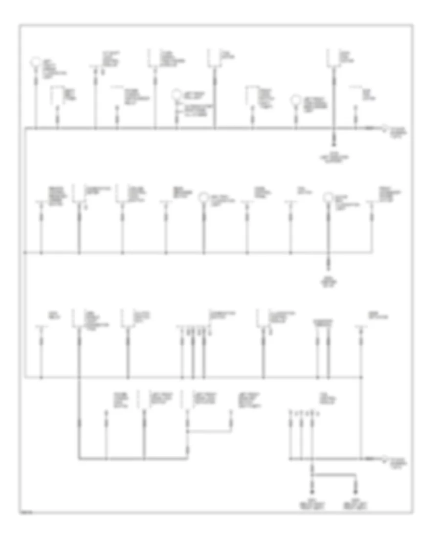
Ground Distribution Wiring Diagram (1 of 3) for Subaru Legacy Brighton 1997
List of elements for Ground Distribution Wiring Diagram (1 of 3) for Subaru Legacy Brighton 1997:
- (m/t)
- (w/o tcs)
- Abs control module
- Abs relay box
- All others
- B31
- B84
- B92
- B93
- B96
- Brake fluid level switch
- Check connector
- Combination meter
- Control module (diagram 2 of 3)
- Cruise control module
- Datalink connector
- Daytime running lights control module
- Door lock module
- Drl resistor
- Engine control module
- From sub fan motor (diagram 2 of 3)
- From tcs
- From trailer connector a (diagram 3 of 3)
- Front wiper motor
- Fuel pump and fuel gauge module (2.2l awd)
- Fwd switch
- G102 (left shock tower)
- G103 (right shock tower)
- G109 (right radiator support)
- G115 (rear of engine)
- G206 (center of i/p)
- G999 (bottom of left "d" pillar)
- I14
- Ignitor
- Neutral position switch (m/t)
- Obd-ii service connector
- Outback step roof model
- Radio
- Rear defogger (sedan)
- Right front door key switch (anti-theft)
- Right front door lock actuator
- Right front door lock switch
- Right front fog light
- Right front turn signal/ side marker light
- Right vanity mirror illumination light
- Security control module
- Shield joint connector (abs)
- Srs harness
- Tcs main relay
- Test mode connector
Ground Distribution Wiring Diagram (2 of 3) for Subaru Legacy Brighton 1997
List of elements for Ground Distribution Wiring Diagram (2 of 3) for Subaru Legacy Brighton 1997:
- A/t shift lock control module
- Abs shield joint connector (tcs)
- All others
- Ash tray illumination light
- B43
- B57
- B69
- B70
- B71
- Clutch switch (m/t)
- Combination meter
- Combination switch
- Cruise control main switch
- Diagnosis terminal
- Fan switch
- Front accessory power outlet
- Front hood switch (anti- theft)
- G108 (left radiator support)
- G202 (center of i/p)
- G300 (below left front seat)
- G301 (below right front seat)
- Glove box illumination light
- I12
- Illumination control module
- Left front door key switch (anti-theft)
- Left front door lock actuator
- Left front door lock switch
- Left front fog light
- Left front turn signal/ side marker light
- Left vanity mirror illumination light
- Main fan motor
- Main relay
- Mode actuator
- Mode control panel
- Outback step roof model
- Power window and sunroof relay
- Power window main switch
- Rear defogger switch
- Remote control rearview mirror switch
- Seat belt timer
- Sub fan motor
- Tcs control module
- Tcs motor
- To g103 (diagram 1 of 3)
- To g109 (diagram 1 of 3)
- Turn signal and hazard module
Ground Distribution Wiring Diagram (3 of 3) for Subaru Legacy Brighton 1997
List of elements for Ground Distribution Wiring Diagram (3 of 3) for Subaru Legacy Brighton 1997:
- (sedan) (wagon)
- Except 2.2l awd
- Fuel gauge module and fuel fump
- G302 (below center console)
- G404 (left rear of luggage compt)
- G404 (wagon) (left rear of luggage compt)
- High mount stop light (sedan)
- High mount stop light (sedan) (spoiler)
- High mount stop light (wagon)
- Key switch (anti- theft)
- Left license plate light (wagon)
- Left rear combination light
- Left rear door lock actuator
- Left rear finisher light (sedan)
- Left rear finisher light (wagon)
- Left seat heater switch (outback step roof model)
- License plate light (sedan)
- Park position switch (a/t)
- Power antenna
- Rear defogger (wagon)
- Rear defogger condenser
- Rear gate latch switch
- Rear gate lock actuator
- Rear wiper motor
- Right license plate light (wagon)
- Right rear combination light
- Right rear door lock actuator
- Right rear finisher light (sedan)
- Right rear finisher light (wagon)
- Right seat heater switch (outback step roof model)
- Shift lock solenoid (a/t)
- To g103 (diagram 1 of 3)
- Trailer connector (outback step roof model)
HEADLIGHTS
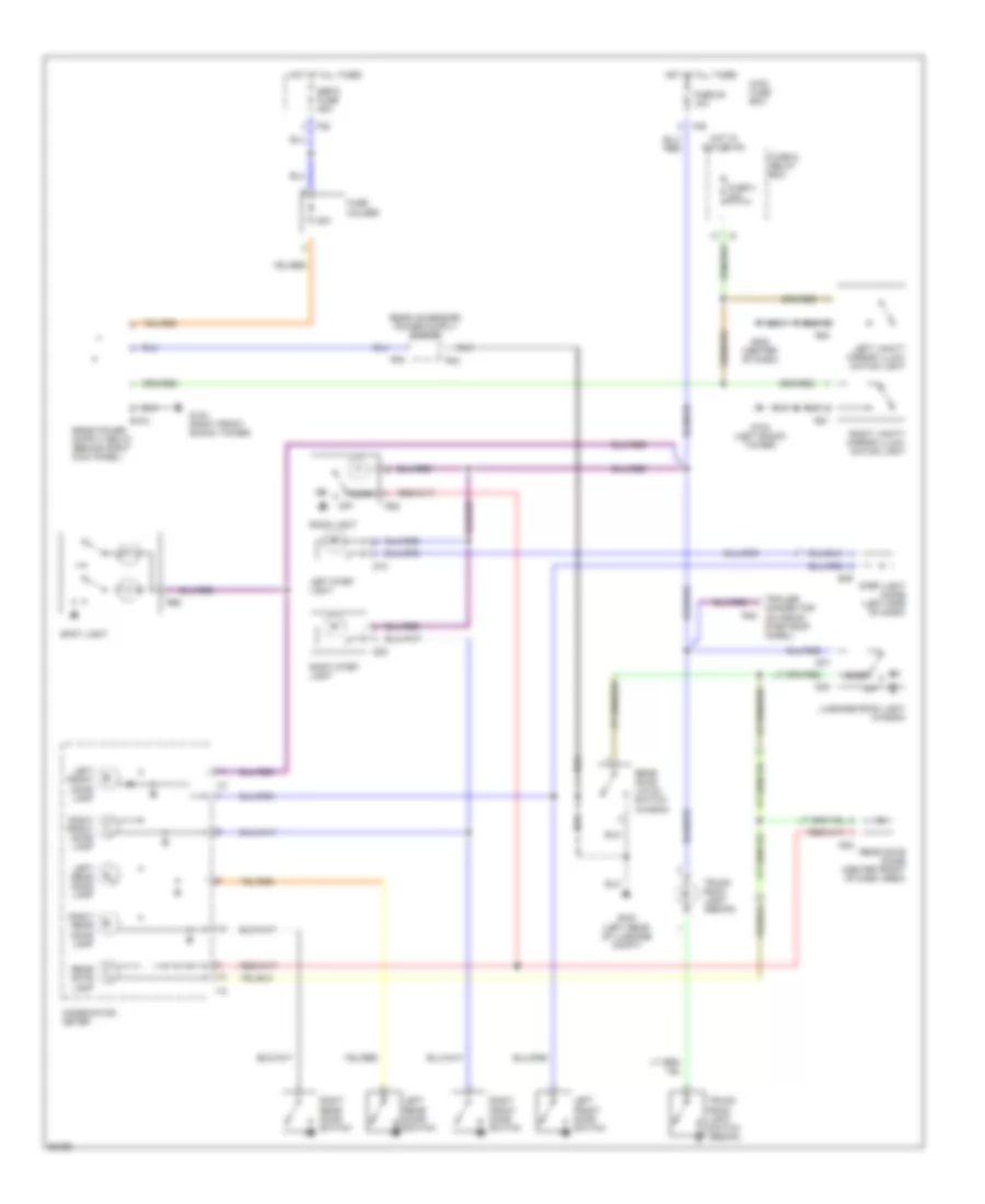
Headlight Wiring Diagram, with DRL for Subaru Legacy Brighton 1997
List of elements for Headlight Wiring Diagram, with DRL for Subaru Legacy Brighton 1997:
- Acc
- Alternator
- B52
- B55
- B69
- B71
- B72 red
- Combination meter
- Combination switch
- Daytime running light diode (right kick panel)
- Daytime running light module (behind right kick panel)
- Daytime running light relay (right kick panel)
- Daytime running light resistor (right side of engine compt)
- Dimmer/ passing switch
- F35
- F39
- Foglight switch
- Front foglight relay (left of steering column)
- Fuse & relay box
- Fuse 15 10a
- Fuse 24 15a
- Fuse 26 15a
- Fuse 6 15a
- G106 (behind left headlight)
- G301 (below right front seat)
- Head
- Hi beam ind
- High-beam relay (right side of dash)
- Hot at all times
- Hot in on and start
- I12
- Ignition switch
- Inhibitor switch (right side of transmission)
- Instrument cluster system (charge indicator)
- Instrument cluster system (park brake warning indicator)
- Interior lights system
- Left fog light
- Left headlight
- Left headlight relay
- Light switch
- Lighting diode (behind glove box)
- Main fuse box
- Off
- Park
- Parking brake switch (base of park brake lever)
- Pass
- Red
- Red/
- Right fog light
- Right headlight
- Right headlight relay
- Start
- Starting circuit
- Transmission control module (left side of dash)
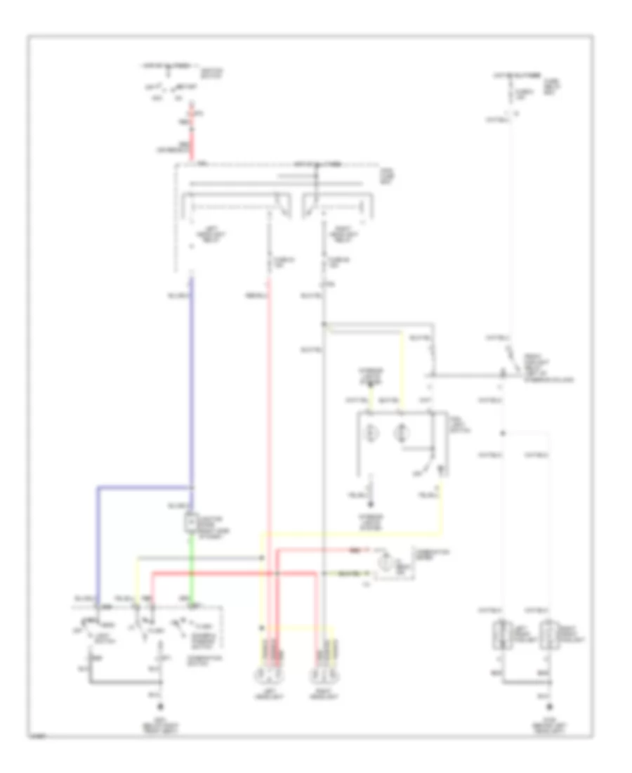
Headlight Wiring Diagram, without DRL for Subaru Legacy Brighton 1997
List of elements for Headlight Wiring Diagram, without DRL for Subaru Legacy Brighton 1997:
- Acc
- B69
- B71
- B72
- Combination meter
- Combination switch
- Dimmer & passing switch
- F35
- F39
- Flash
- Fog- light switch
- Front foglight relay (left of steering column)
- Fuse 24 15a
- Fuse 26 15a
- Fuse 6 15a
- Fuse/ relay box
- G106 (behind left headlight)
- G301 (below right front seat)
- Hi beam ind
- Hot at all times
- I12
- Ignition switch
- Interior lights system
- Left front foglight
- Left headlight
- Left headlight relay
- Light switch
- Lighting diode (right side of dash)
- Main fuse box
- Off
- Park head
- Red
- Right front foglight
- Right headlight
- Right headlight relay
- Start
HORN
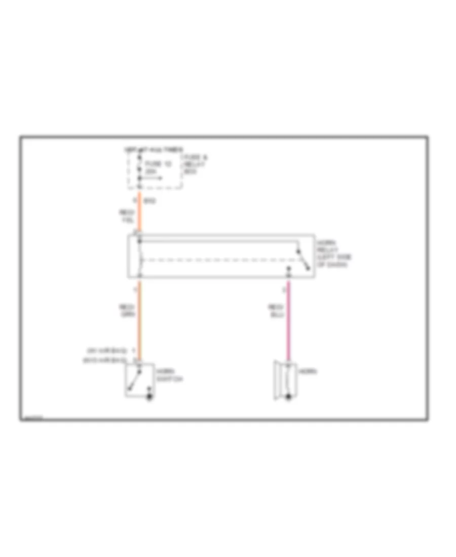
Horn Wiring Diagram for Subaru Legacy Brighton 1997
List of elements for Horn Wiring Diagram for Subaru Legacy Brighton 1997:
- (w/ air bag)
- (w/o air bag)
- B52
- Fuse & relay box
- Fuse 12 20a
- Horn
- Horn relay (left side of dash)
- Horn switch
- Hot at all times
INSTRUMENT CLUSTER
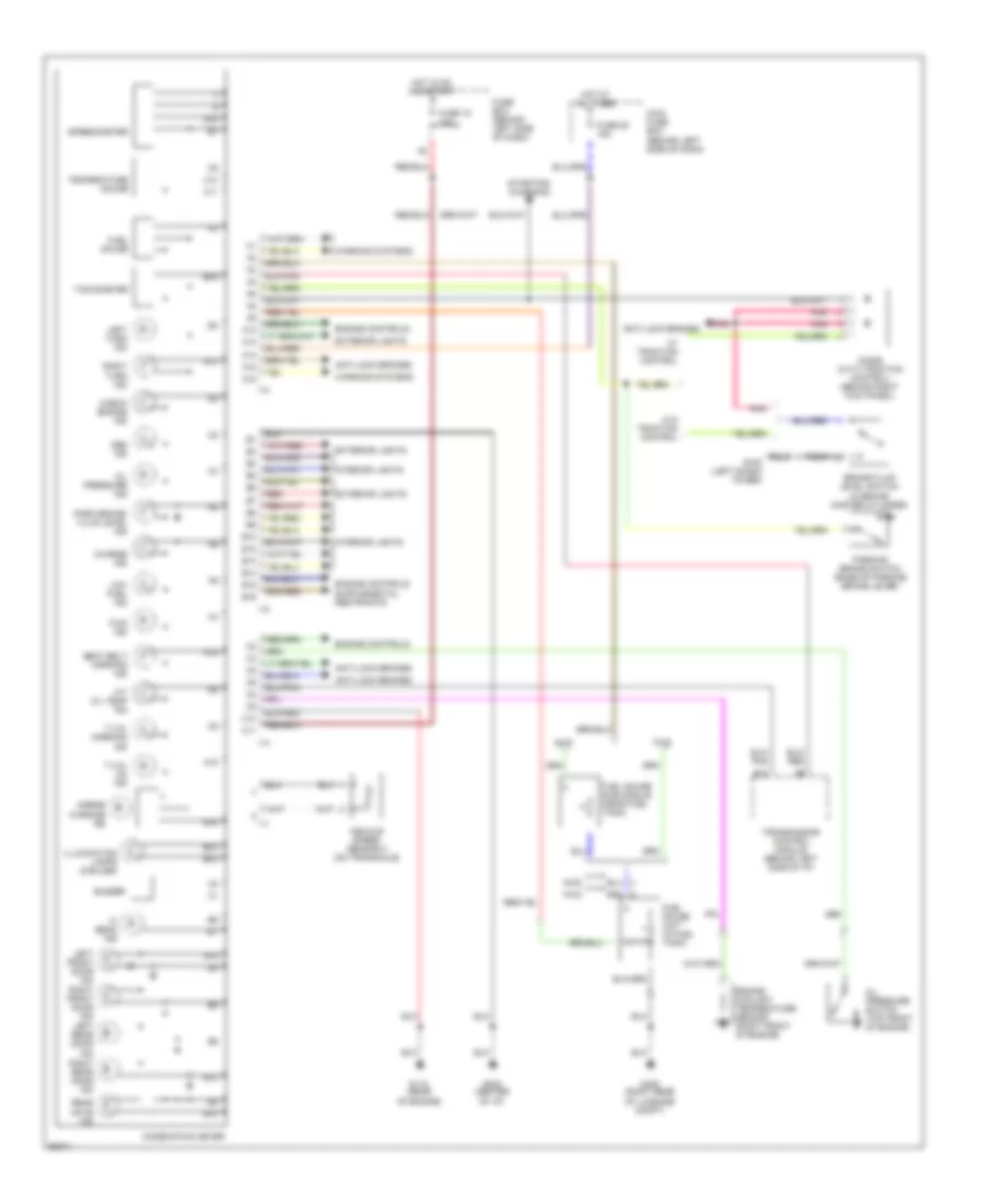
Instrument Cluster Wiring Diagram for Subaru Legacy Brighton 1997
List of elements for Instrument Cluster Wiring Diagram for Subaru Legacy Brighton 1997:
- A/t oil temp ind
- A10
- A13
- A14
- A15
- A16
- Abs ind
- Airbag warning ind
- Anti-lock brakes
- Awd
- B10
- B12
- B13
- B14
- B15
- B16
- Brake fluid level switch (in brake master cylinder)
- Buzzer
- C10
- C11
- Charge ind
- Check engine ind
- Combination meter
- Diode (with traction control) (behind right kick panel)
- Engine controls
- Engine coolant temperature sensor (right front of engine)
- Exterior lights
- Fuel gauge
- Fuel gauge sub module (near fuel tank)
- Fuel gauge unit (in fuel tank)
- Fuse 15 10a
- Fuse 25 15a
- Fuse box (behind left side of dash)
- Fwd
- Fwd ind
- G102 (left shock tower)
- G115 (rear of engine)
- G202 (center of i/p)
- G405 (right rear of luggage compt)
- Hi beam ind
- Hot at all times
- Hot in on and start
- I10
- I11
- I12
- I14
- Illumination lamps (6 bulbs)
- Interior lights
- Left front door ind
- Left rear door ind
- Left turn ind
- Low fuel ind
- Main fuse box (behind left side of dash)
- Oil pressure ind
- Oil pressure switch (top front of engine)
- Park brake/ fluid level ind
- Parking brake switch (base of parking brake lever)
- Pnk
- Rear gate ind
- Red
- Right front door ind
- Right rear door ind
- Right turn ind
- Seat belt warning ind
- Speedometer
- Starting/ charging
- T.c.s. on ind
- T.c.s. warning ind
- Tachometer
- Temperature gauge
- Transmission control module (behind left side of i/p)
- Vehicle speed sensor 2 (on transaxle)
- W/ traction control
- W/o traction control
- Warning systems
INTERIOR LIGHTS
Courtesy Lamps Wiring Diagram for Subaru Legacy Brighton 1997
List of elements for Courtesy Lamps Wiring Diagram for Subaru Legacy Brighton 1997:
- 20a
- B104
- B35
- Combination meter
- Connector (outback step roof model)
- D10
- D20
- D37
- D38
- Door
- F35
- F36
- Fuse & relay box
- Fuse 25 10a
- Fuse 3 20a
- Fuse holder
- G102 (left shock tower)
- G103 (right front shock tower)
- G202 (center of dash)
- G404 (left rear of luggage compt)
- Hot at all times
- Hot in acc or on
- I10
- I12
- Left front door lamp
- Left front door switch
- Left rear door lamp
- Left rear door switch
- Left step light
- Left vanity mirror illumi- nation light
- Luggage room light (wagon)
- Main fuse box
- Off
- R30
- R32
- R33
- R45
- R51
- R52
- R54
- R56
- Rear gate diode (center front of dash area)
- Rear gate lamp
- Rear gate latch switch (wagon)
- Right front door lamp
- Right front door switch
- Right rear door lamp
- Right rear door switch
- Right step light
- Right vanity mirror illumi- nation light
- Room light
- Sbf-5 fuse 45a
- Spot light
- Step light diode (left side of dash)
- Trailer
- Trunk room light (sedan)
- Trunk room light switch (sedan)
Instrument Illumination Wiring Diagram for Subaru Legacy Brighton 1997
List of elements for Instrument Illumination Wiring Diagram for Subaru Legacy Brighton 1997:
- A/t selector lever illumination light
- Ashtray illumination light
- B43
- B51
- B69
- Cd player illumination light
- Combination meter
- Combination switch
- Cruise control main switch illumination light
- F35
- F40
- Front fog- light switch illumination light
- Fuse & relay box
- Fuse 23 20a
- Fuse 9 10a
- G202 (center of dash)
- Glove box illumi- nation light
- Hazard switch illumination light
- Head
- Hot at all times
- Hot in on & start
- I12
- Illumination control module (left of steering column)
- Illumination light
- Left seat heater switch illumination light (outback step roof model)
- Light switch
- Main fuse box
- Mode control panel illumination light
- Nca
- Off
- Park
- Radio illumination light
- Rear defogger switch illumination light
- Right seat heater switch illumination light (outback step roof model)
- Tail & illumination relay
- Tcf off switch illumination light
POWER ANTENNA
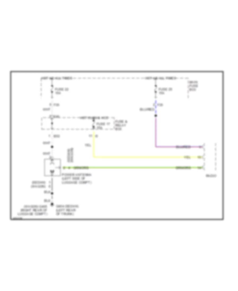
Power Antenna Wiring Diagram for Subaru Legacy Brighton 1997
List of elements for Power Antenna Wiring Diagram for Subaru Legacy Brighton 1997:
- (sedan)
- (sedan) (wagon)
- (wagon)
- (wagon) g405 (right rear of luggage compt)
- B52
- F35
- F40
- Fuse & relay box
- Fuse 17 15a
- Fuse 22 15a
- Fuse 25 15a
- G404 (sedan) (left rear of trunk)
- Hot at all times
- Hot in on & acc
- Main fuse box
- Power antenna (left side of luggage compt)
- Radio
POWER DISTRIBUTION
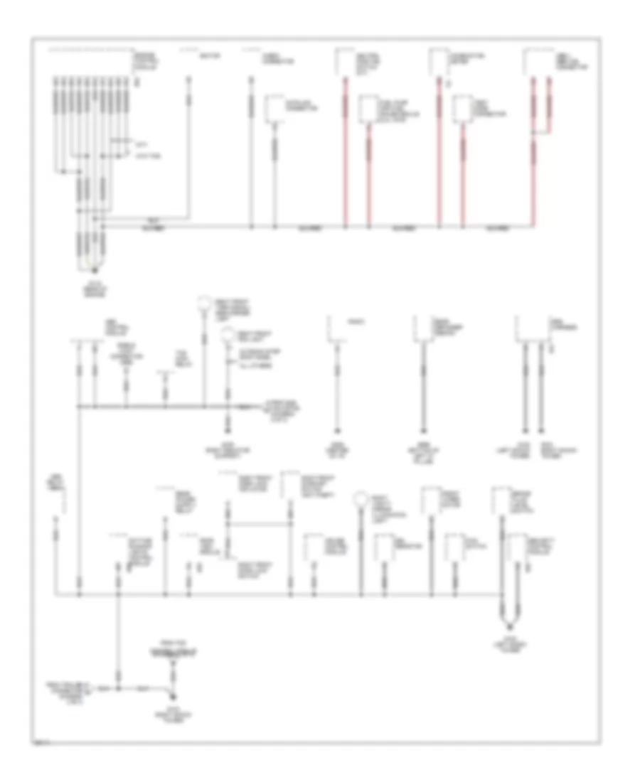
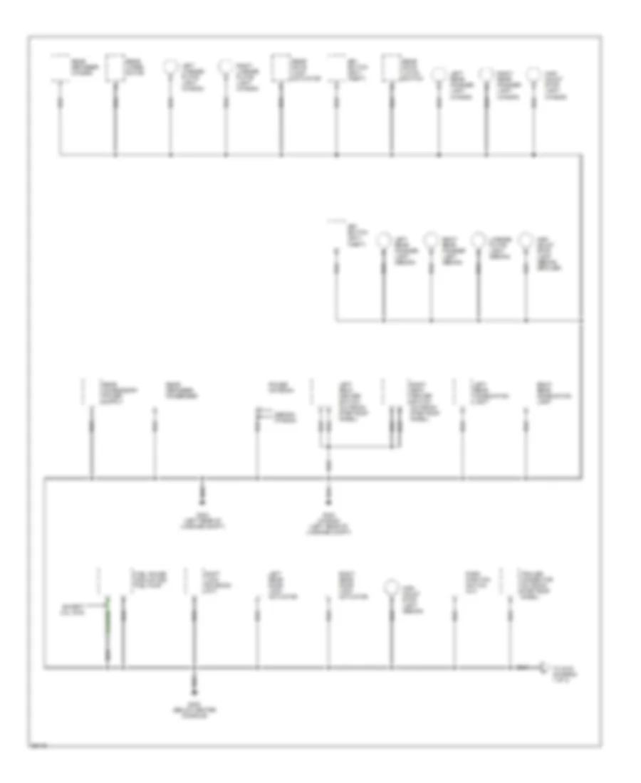
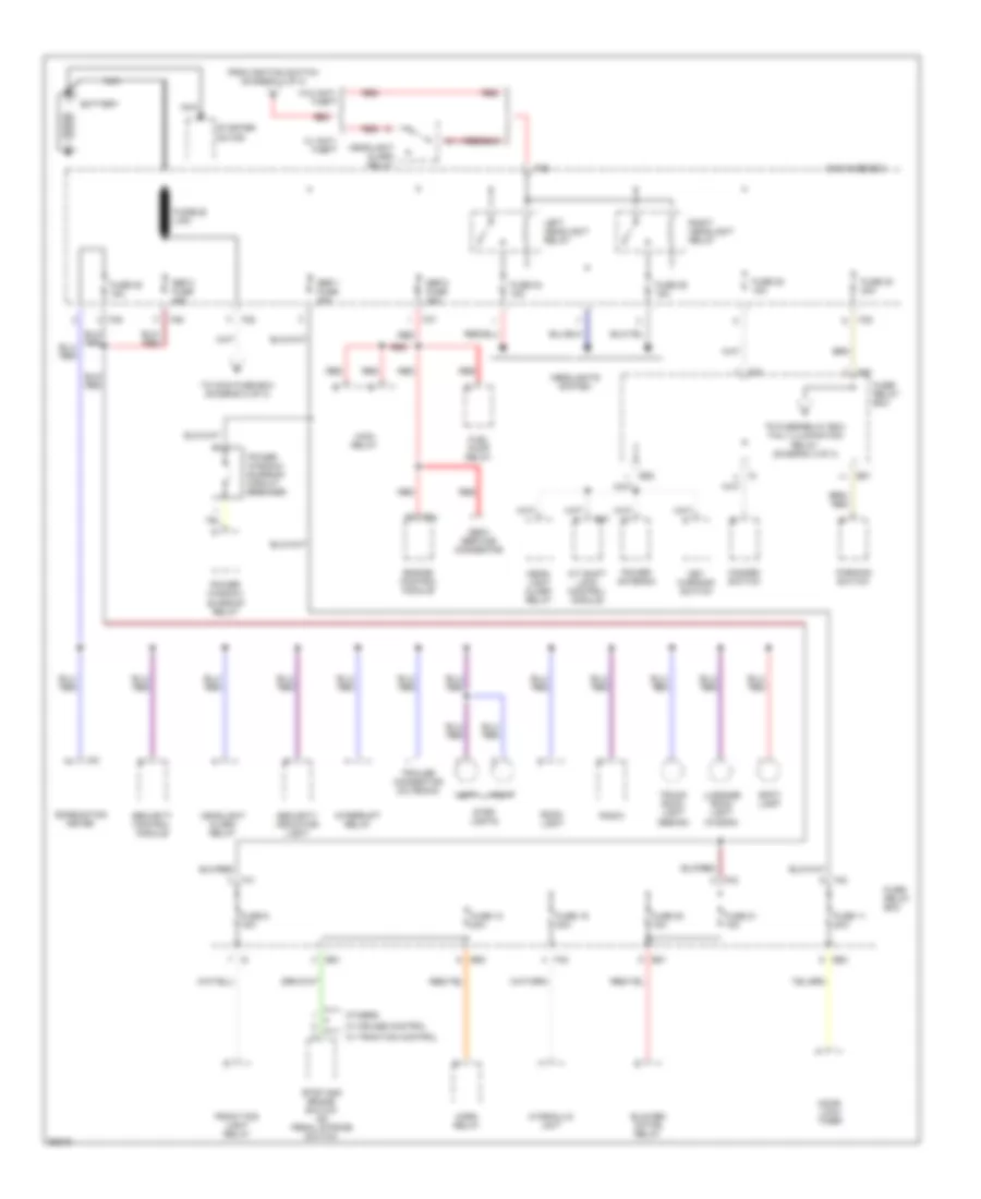
Power Distribution Wiring Diagram (1 of 3) for Subaru Legacy Brighton 1997
List of elements for Power Distribution Wiring Diagram (1 of 3) for Subaru Legacy Brighton 1997:
- A/t shift lock control module
- B51
- B52
- B57
- B84
- Battery
- Blower motor relay
- Combination meter
- Door lock timer
- Engine control module
- F35
- F36
- F37
- F38
- F39
- F40
- F41
- F42
- From ignition switch (diagram 2 of 3)
- Front fog light relay
- Fuel pump relay
- Fuse 11 20a
- Fuse 12 20a
- Fuse 19 20a
- Fuse 20 15a
- Fuse 21 15a
- Fuse 22 15a
- Fuse 23 20a
- Fuse 24 15a
- Fuse 25 15a
- Fuse 26 15a
- Fuse 6 15a
- Fuse/ relay box
- Fusible link
- Hazard switch
- Head- light alarm relay
- Headlight alarm relay
- Headlights system
- Horn relay
- Hydraulic unit
- I10
- Interrupt relay
- Key warning switch
- Left
- Left headlight relay
- Luggage room light (wagon)
- Main fuse box
- Main relay
- Nca
- Obd-ii service connector
- Others
- Parking switch
- Power antenna
- Power window/ sunroof circuit breaker
- Power window/ sunroof relay
- Radio
- Red
- Right
- Right headlight relay
- Room light
- Sbf-1 fuse 30a
- Sbf-2 fuse 30a
- Sbf-3 fuse 45a
- Security control module
- Security indicator light
- Spot light
- Starter motor
- Step lights
- Stop and brake switch or pedal stroke switch
- To fuse/relay box tail/ illumination relay (diagram 3 of 3)
- To main fuse box (diagram 2 of 3)
- Trailer connector (outback)
- Trunk room light (sedan)
- W/ anti- theft
- W/ cruise control
- W/ traction control
- W/o anti- theft
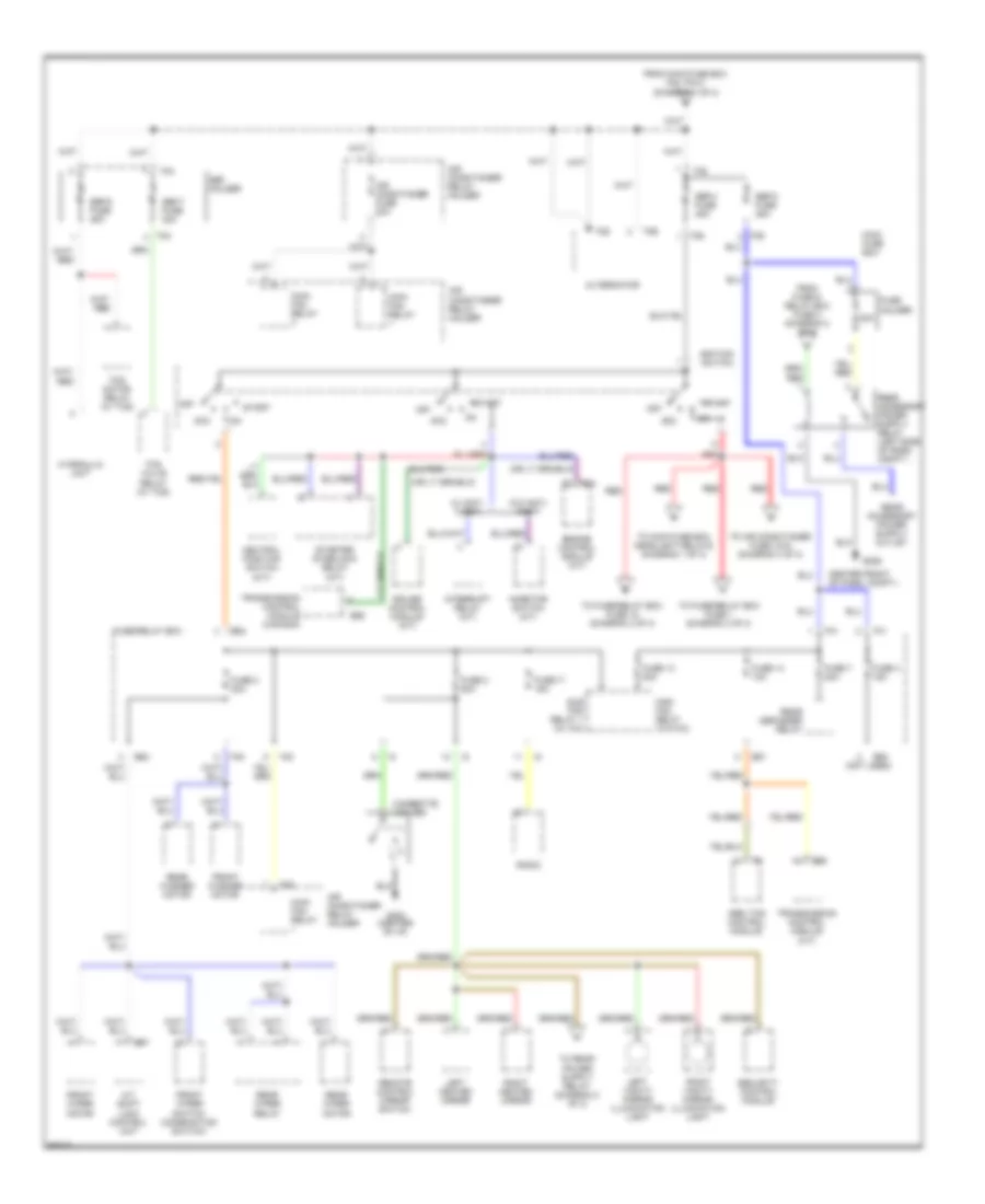
Power Distribution Wiring Diagram (2 of 3) for Subaru Legacy Brighton 1997
List of elements for Power Distribution Wiring Diagram (2 of 3) for Subaru Legacy Brighton 1997:
- (not used)
- 20a
- A/t shift lock control unit
- Abs/ tcs control module
- Acc
- Air conditioner fuse 20a
- Air conditioner relay holder
- Alternator
- B51
- B52
- B56
- B57
- B84
- Center front of pass. compt.)
- Cigarette lighter
- Cruise control module (a/t)
- Engine control module (a/t)
- F25
- F26
- F28
- F34
- F36
- F38
- F40
- F41
- From fuse & relay box fuse 3 (diagram 2 of 3)
- From main fuse box f38, pin 2 (diagram 1 of 3)
- Front washer motor
- Front wiper motor
- Front wiper switch (combination switch)
- Fuse 13 20a
- Fuse 14 10a
- Fuse 17 15a
- Fuse 2 20a
- Fuse 3 20a
- Fuse 4 15a
- Fuse 7 20a
- Fuse holder
- Fuse/relay box
- G202 (center of i/p)
- G206
- Hydraulic unit
- Ignition switch
- Inhibitor switch (a/t)
- Interrupt relay (a/t)
- Left heated mirror
- Left vanity mirror illumination light
- Main fan relay
- Main fan relay (w/o a/c)
- Main fuse box
- Neutral position switch (m/t)
- Off
- Radio
- Rear defogger relay
- Rear washer motor
- Rear wiper motor
- Rear wiper relay
- Red
- Remote control mirror switch
- Right heated mirror
- Right vanity mirror illumination light
- Sbf holder
- Sbf-4 fuse 45a
- Sbf-5 fuse 45a
- Sbf-6 fuse 45a
- Sbf-7 fuse 30a
- Security control module
- Start
- Starter interlock relay (m/t)
- Sub fan relay 1 (w/ a/c)
- Tcs motor relay (w/ tcs)
- Tcs valve relay (w/ tcs)
- To air conditioner fuse (10a) (diagram 3 of 3)
- To fuse/relay box fuse 1 (diagram 3 of 3)
- To fuse/relay box fuse 18 (diagram 3 of 3)
- To main fuse box headlight relays (diagram 1 of 3)
- Transmission control module (a/t)
- Transmission control module (canada)
- W/ anti- theft
- W/o anti- theft
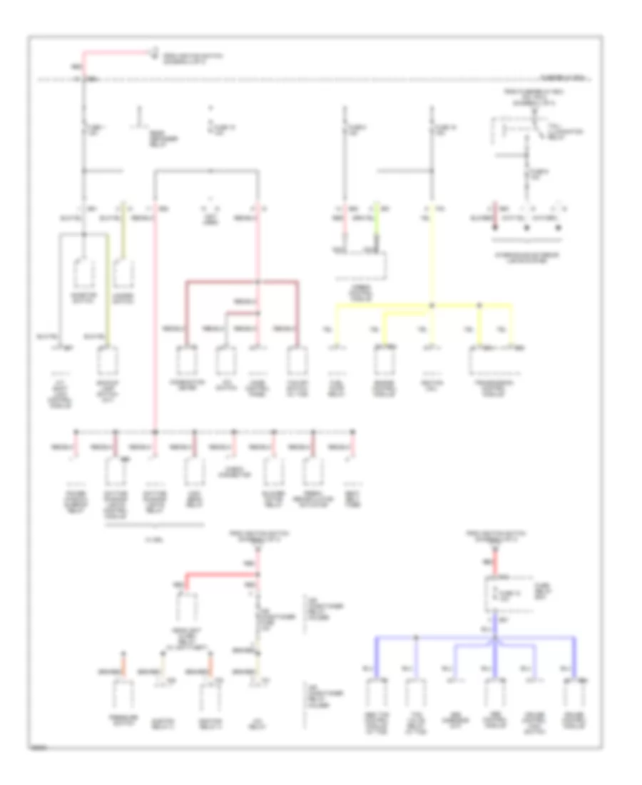
Power Distribution Wiring Diagram (3 of 3) for Subaru Legacy Brighton 1997
List of elements for Power Distribution Wiring Diagram (3 of 3) for Subaru Legacy Brighton 1997:
- (not used)
- A/c relay
- A/c switch
- A/t shift lock control module
- Abs control module
- Abs g-sensor (m/t)
- Abs/ tcs control module (w/ tcs)
- Air conditioner fuse 10a
- Air conditioner relay holder
- Airbag control module
- B51
- B52
- B54
- B55
- B57
- B84
- B94
- B96
- Backup lamp switch (m/t)
- Blower motor relay
- Check connector
- Combination meter
- Cruise control main switch
- Cruise control module
- Daytime running lights control module
- Daytime running lights relay
- Engine control module
- F29
- F30
- F31
- F40
- F42
- Fresh/ recirculator actuator
- From fuse/relay box f40, pin 2 (diagram 1 of 3)
- From ignition switch (diagram 2 of 3)
- Fuel pump relay
- Fuse 1 15a
- Fuse 15 10a
- Fuse 16 15a
- Fuse 18 10a
- Fuse 8 15a
- Fuse 9 10a
- Fuse/ relay box
- Fuse/relay box
- Hazard switch
- Headlight alarm relay (w/ anti-theft)
- High beam relay
- I14
- Ignition coil
- Inhibitor switch
- Interior and exterior lights system
- Main fan relay 2
- Mode control panel
- Nca
- Power window/ sunroof relay
- Pressure switch
- Rear defogger relay
- Red
- Seat belt timer
- Sub fan relay 2
- Tail/ illumination relay
- Tcs off switch (w/ tcs)
- Tcs valve relay (w/ tcs)
- Transmission control module
- W/ drl
POWER DOOR LOCKS
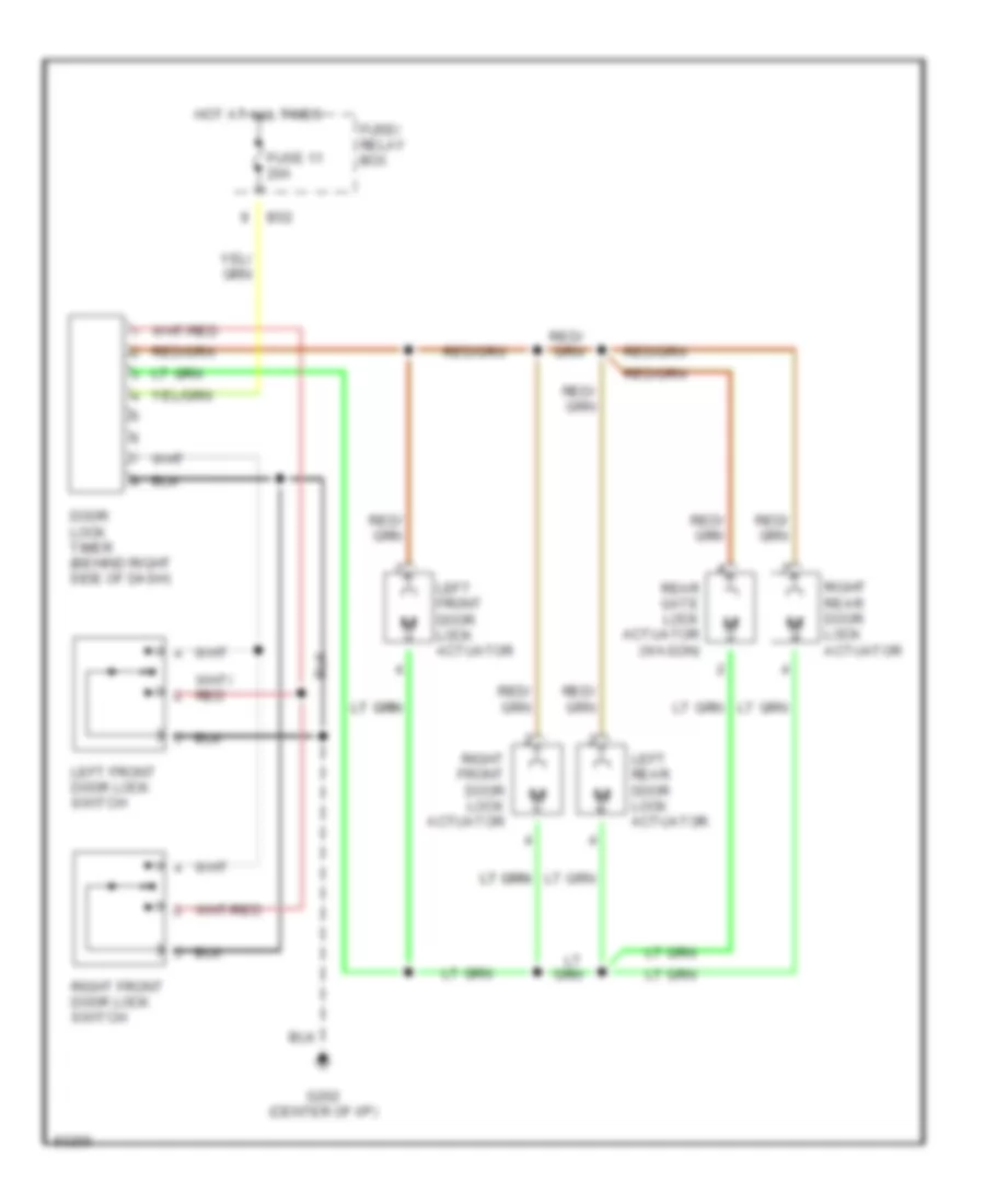
Power Door Lock Wiring Diagram for Subaru Legacy Brighton 1997
List of elements for Power Door Lock Wiring Diagram for Subaru Legacy Brighton 1997:
- B52
- Door lock timer (behind right side of dash)
- Fuse 11 20a
- Fuse/ relay box
- G202 (center of i/p)
- Hot at all times
- Left front door lock actuator
- Left front door lock switch
- Left rear door lock actuator
- Rear gate lock actuator (wagon)
- Right front door lock actuator
- Right front door lock switch
- Right rear door lock actuator
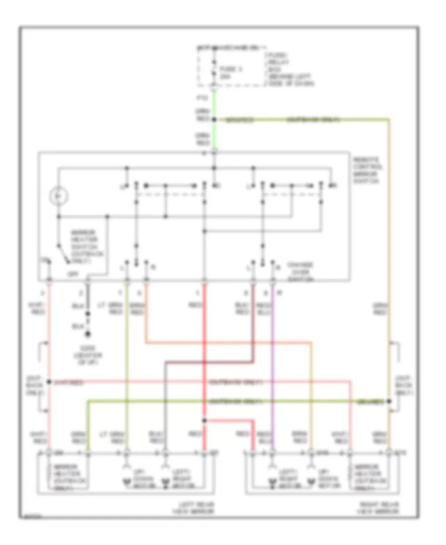
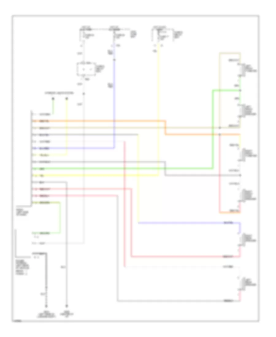
POWER MIRRORS
Power Mirror Wiring Diagram for Subaru Legacy Brighton 1997
List of elements for Power Mirror Wiring Diagram for Subaru Legacy Brighton 1997:
- (out- back only)
- (outback only)
- Change over switch
- D15
- D16
- F13
- Fuse 3 20a
- Fuse/ relay box (behind left side of dash)
- G202 (center of i/p)
- Hot in acc and on
- Left rear view mirror
- Left/ right m
- Mirror heater (outback only)
- Mirror heater switch (outback only)
- Motor
- Off
- Red
- Remote control mirror switch
- Right rear view mirror
- Up/ down m
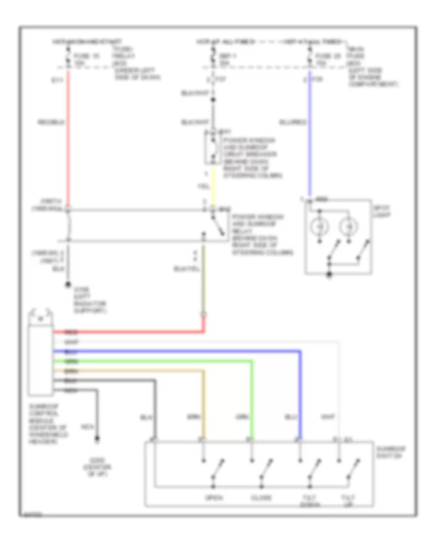
POWER TOP/SUNROOF
Sunroof Wiring Diagram for Subaru Legacy Brighton 1997
List of elements for Sunroof Wiring Diagram for Subaru Legacy Brighton 1997:
- (1995-96)
- (1995-96) (1997)
- (1997)
- B41
- B42
- Close
- E11
- F35
- F37
- Fuse 15 10a
- Fuse 25 15a
- Fuse/ relay box (under left side of dash)
- G108 (left radiator support)
- G202 (center of i/p)
- Hot at all times
- Hot in on and start
- Main fuse box (left side of engine compartment)
- Nca
- Open
- Power window and sunroof ciruit breaker (behind dash, right side of steering colimn)
- Power window and sunroof relay (behind dash, right side of steering column)
- R56
- Red
- Sbf-1 30a
- Spot light
- Sunroof control module (center of windshield header)
- Sunroof switch
- Tilt down
- Tilt up
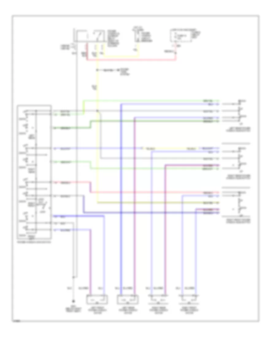
POWER WINDOWS
Power Window Wiring Diagram for Subaru Legacy Brighton 1997
List of elements for Power Window Wiring Diagram for Subaru Legacy Brighton 1997:
- (1995-96)
- (1997-98)
- B52
- Down
- Front left
- Fuse & relay box
- Fuse 15 10a
- G301 (below right front seat)
- Hot at all times
- Hot in on and start
- Left front power window motor
- Left rear
- Left rear power window motor
- Left rear power window sub switch
- Lock
- Lock- out switch
- Power tops system
- Power window & sunroof relay (right of steering column)
- Power window circuit breaker
- Power window main switch
- Right front
- Right front power window motor
- Right front power window sub switch
- Right rear
- Right rear power window motor
- Right rear power window sub switch
RADIO
Radio Wiring Diagrams for Subaru Legacy Brighton 1997
List of elements for Radio Wiring Diagrams for Subaru Legacy Brighton 1997:
- B52
- F35
- F40
- Fuse & relay box
- Fuse 17 15a
- Fuse 22 15a
- Fuse 25 15a
- G206 (center of i/p)
- G404 (left rear of luggage compt)
- Hot at all times
- Hot in acc & on
- Interior lights system
- Left front door speaker
- Left front tweeter
- Left rear speaker
- Main fuse box
- Power antenna (left rear of vehicle)
- Radio (left side of dash)
- Right front door speaker
- Right front tweeter
- Right rear speaker
- Sedan
- Wagon
SHIFT INTERLOCKS
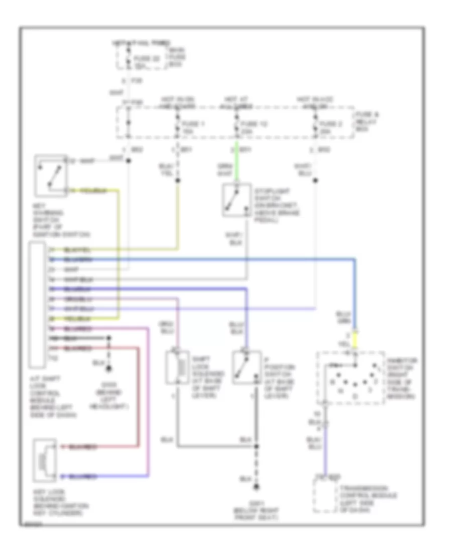
Shift Interlock Wiring Diagram for Subaru Legacy Brighton 1997
List of elements for Shift Interlock Wiring Diagram for Subaru Legacy Brighton 1997:
- A/t shift lock control module (behind left side of dash)
- B51
- B52
- B55
- F35
- F40
- Fuse & relay box
- Fuse 1 15a
- Fuse 12 20a
- Fuse 2 20a
- Fuse 22 15a
- G106 (behind left headlight)
- G301 (below right front seat)
- Hot at all times
- Hot in acc and on
- Hot in on and start
- Inhbitor switch (right side of trans- mission)
- Key lock solenoid (behind ignition key cylinder)
- Key warning switch (part of ignition switch)
- Main fuse box
- P position switch (at base of shift lever)
- Shift lock solenoid (at base of shift lever)
- Stoplight switch (on bracket, above brake pedal)
- Transmission control module (left side of dash)
STARTING/CHARGING
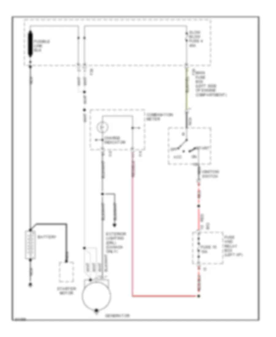
Charging Wiring Diagram for Subaru Legacy Brighton 1997
List of elements for Charging Wiring Diagram for Subaru Legacy Brighton 1997:
- Acc
- B52
- Battery
- Charge indicator
- Combination meter
- Exterior lighting (drl) (canada only)
- F36
- F38
- Fuse 15 10a
- Fuse and relay box (left i/p)
- Generator
- I10
- I14
- Ignition switch
- Main fuse box (left side of engine compartment)
- Nca
- Nca b
- Off
- Red
- Slow blow fuse 4 45a
- Start
- Starter motor
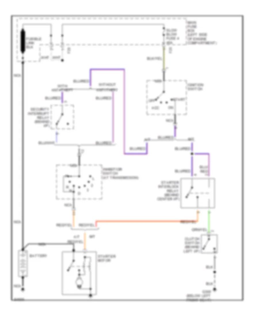
Starting Wiring Diagram for Subaru Legacy Brighton 1997
List of elements for Starting Wiring Diagram for Subaru Legacy Brighton 1997:
- A/t
- Acc
- Anti-theft
- Battery
- Clutch switch (behind left i/p)
- F25
- F29
- G300 (below left front seat)
- Ignition switch
- Inhibitior switch (at transmission)
- M/t
- Main fuse box (left side of engine compartment)
- Nca
- Off
- Security interrupt relay (behind i/p)
- Slow blow fuse 4 45a
- Start
- Starter interlock relay (behind center i/p)
- Starter motor
- With anti-theft
- Without
SUPPLEMENTAL RESTRAINTS
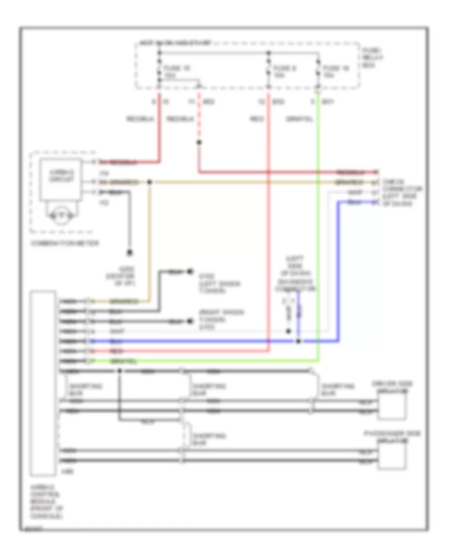
Supplemental Restraint Wiring Diagram for Subaru Legacy Brighton 1997
List of elements for Supplemental Restraint Wiring Diagram for Subaru Legacy Brighton 1997:
- (left side of dash)
- (right shock tower) g103
- Ab6
- Airbag circuit
- Airbag control module (front of console)
- B51
- B52
- Check connector (left side of dash)
- Combination meter
- Diagnosis connector
- Driver side inflator
- Fuse 15 10a
- Fuse 16 15a
- Fuse 8 15a
- Fuse/ relay box
- G102 (left shock tower)
- G202 (center of i/p)
- Hot in on and start
- I12
- I14
- Nca
- Passenger side inflator
- Red
- Shorting bar
- Shorting bar nca
TRANSMISSION
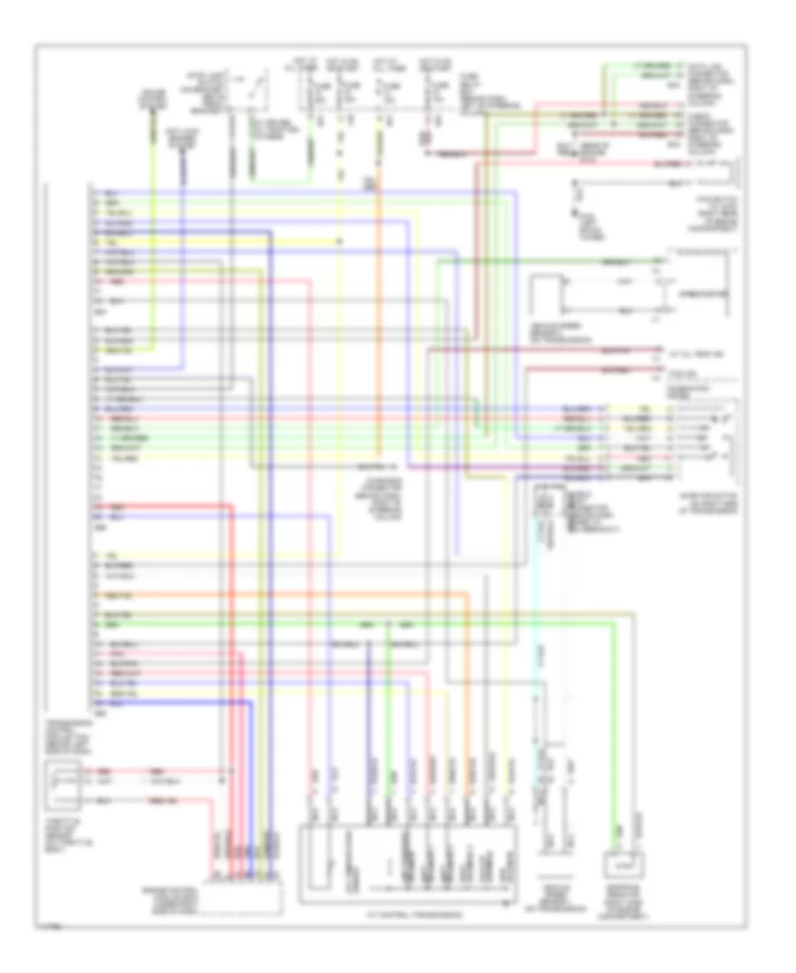
A/T Wiring Diagram for Subaru Legacy Brighton 1997
List of elements for A/T Wiring Diagram for Subaru Legacy Brighton 1997:
- (on right side of transmission)
- (rear of engine) g115
- (right side of engine compartment)
- (w/ cruise) (w/ traction) (others)
- A/t control (transmission)
- A/t oil temp ind
- Anti-lock brakes system
- Atf temperature sensor
- Awd solenoid
- B51
- B52
- B54
- B55
- B56
- B78
- B79
- Check connector (behind dash, right of steering column)
- Combination meter
- Cruise control system
- Data link connector (behind dash, right of steering column)
- Diagnosis connector (behind dash, right of steering column)
- Dropping resistor
- Engine control module (ecm) (under right side of dash)
- F40
- Fuse 10a
- Fuse 15a
- Fuse 20a
- Fuse/ relay box (behind dash, left of steering column)
- Fwd ind
- Fwd switch (w/ awd) (right rear of engine compartment)
- G102 (left shock tower)
- Hot at all times
- Hot in on or start
- I10
- I11
- I14
- Inhibitor switch
- Lock-up solenoid
- Nca
- Pnk
- Red
- Shield joint connector (behind dash, nca
- Shift solenoid 1
- Shift solenoid 3
- Solenoid 2 shift
- Solenoid line pressure
- Speedometer
- Stop lamp switch (on bracket above pedal bracket)
- Taped to tcm breakout)
- Throttle position sensor (on throttle body)
- Transmission control module (tcm) (behind left side of dash)
- Vehicle speed sensor 1 (on transmission)
- Vehicle speed sensor 2 (on transmission)
WARNING SYSTEMS
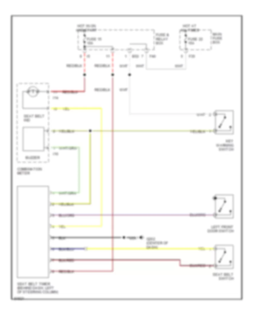
Warning System Wiring Diagrams for Subaru Legacy Brighton 1997
List of elements for Warning System Wiring Diagrams for Subaru Legacy Brighton 1997:
- B52
- Buzzer
- Combination meter
- F35
- F40
- Fuse & relay box
- Fuse 15 10a
- Fuse 22 15a
- G202 (center of dash)
- Hot at all times
- Hot in on and start
- I10
- I14
- Key warning switch
- Left front door switch
- Main fuse box
- Seat belt ind
- Seat belt switch
- Seat belt timer (behind dash, left of steering column)
WIPER/WASHER
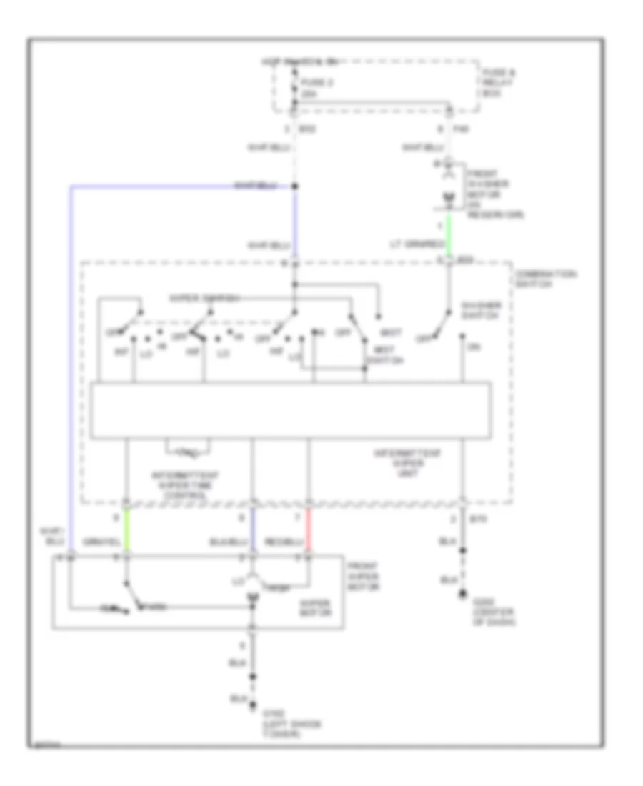
Front Wiper/Washer Wiring Diagram for Subaru Legacy Brighton 1997
List of elements for Front Wiper/Washer Wiring Diagram for Subaru Legacy Brighton 1997:
- B52
- B70
- Combination switch
- F40
- Front washer motor (in reservoir)
- Front wiper motor
- Fuse & relay box
- Fuse 2 20a
- G102 (left shock tower)
- G202 (center of dash)
- High
- Hot in acc & on
- Int
- Intermittent wiper time control
- Intermittent wiper unit
- Mist
- Mist switch
- Off
- Park
- Run
- Washer switch
- Wiper motor
- Wiper switch
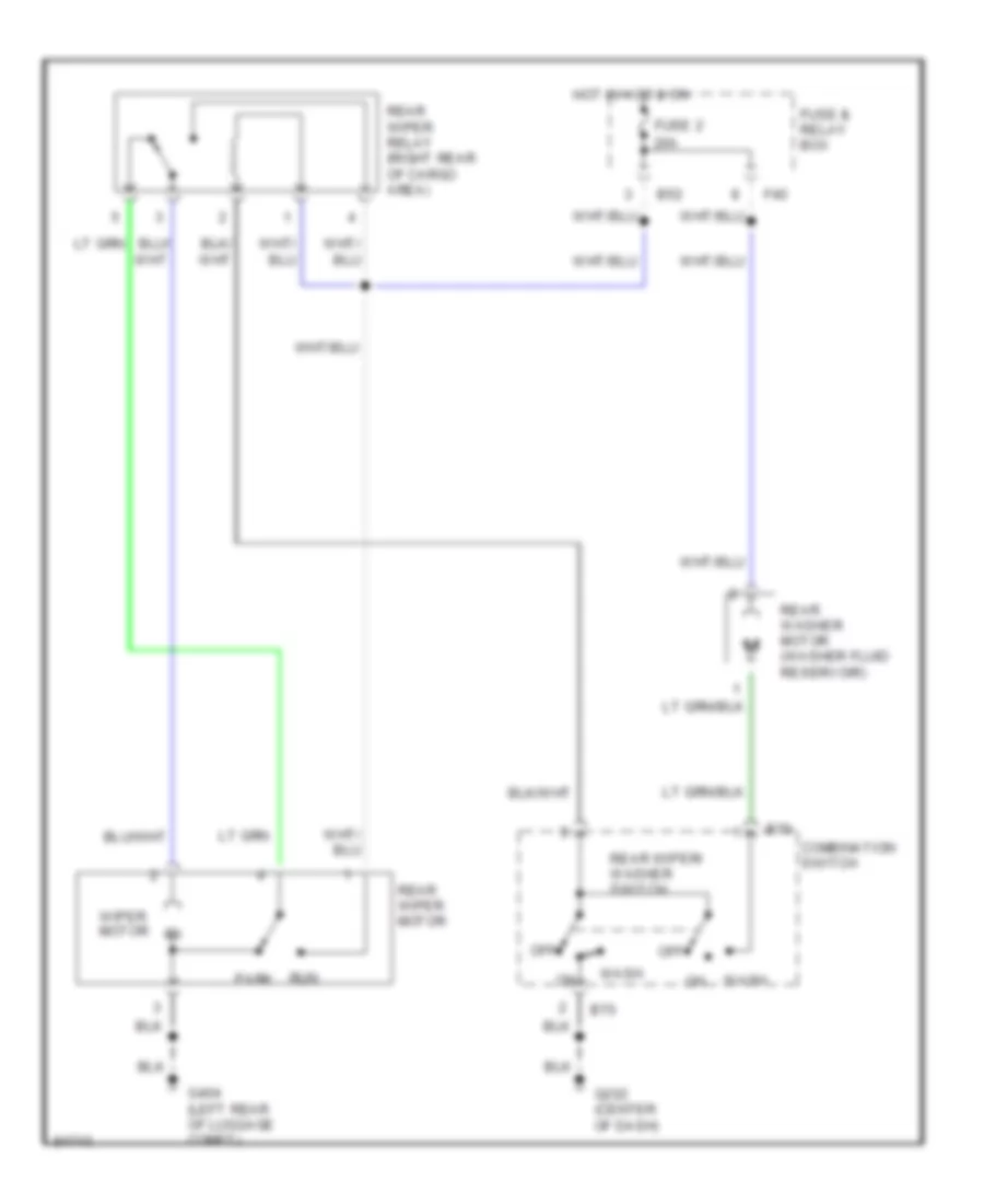
Rear Wiper/Washer Wiring Diagram for Subaru Legacy Brighton 1997
List of elements for Rear Wiper/Washer Wiring Diagram for Subaru Legacy Brighton 1997:
- B52
- B70
- Combination switch
- F40
- Fuse & relay box
- Fuse 2 20a
- G202 (center of dash)
- G404 (left rear of luggage compt)
- Hot in acc & on
- Off
- Park
- Rear washer motor (washer fluid reservoir)
- Rear wiper motor
- Rear wiper relay (right rear of cargo area)
- Rear wiper/ washer switch
- Run
- Wash
- Wiper motor

 Dansk
Dansk Deutsch
 Ελληνικά
 English
 English
 Español
 Suomi
Suomi Français
 Français
 עברית
עברית Hrvatski
 Magyar
 Italiano
 日本語
日本語 한국어
한국어 Nederlands
 Polski
 Português
 Português
 Română
 Русский
 Slovenčina
 Slovenščina
 Svenska
 Türkçe
 中文 (中国)