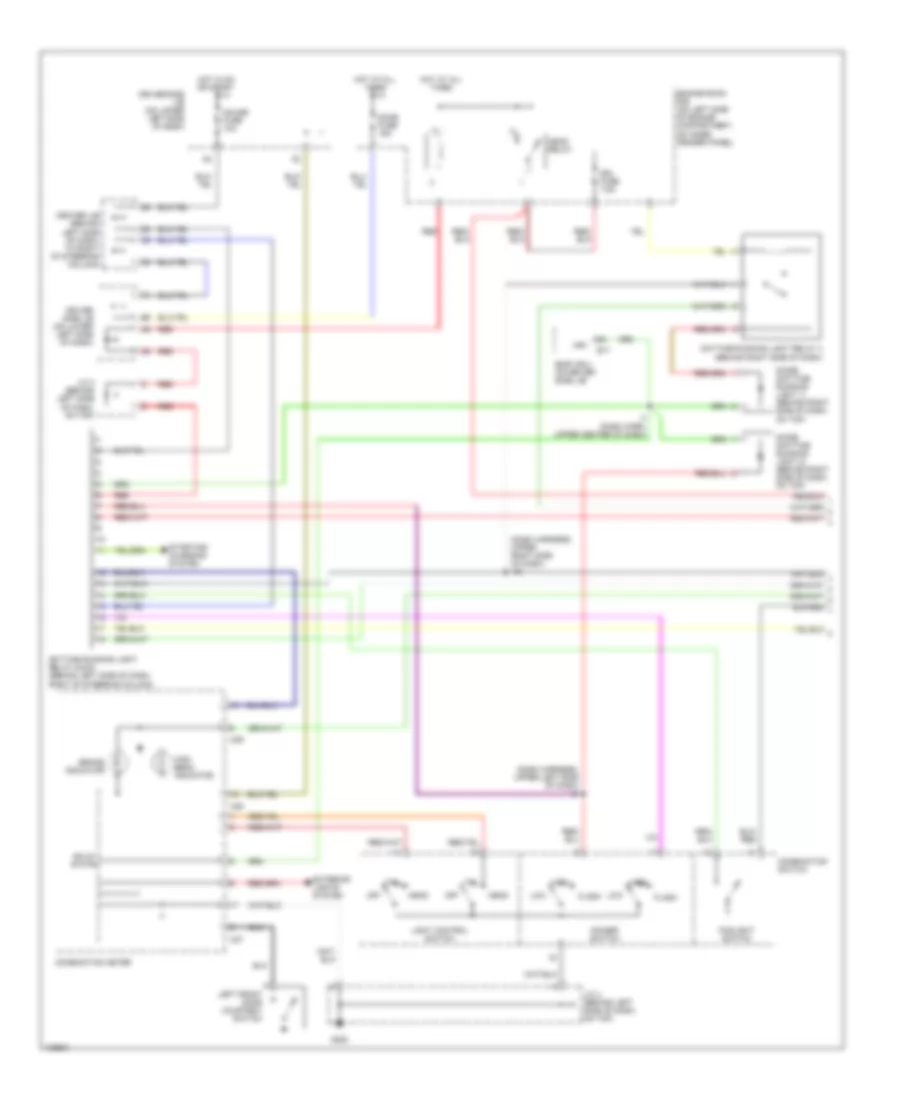
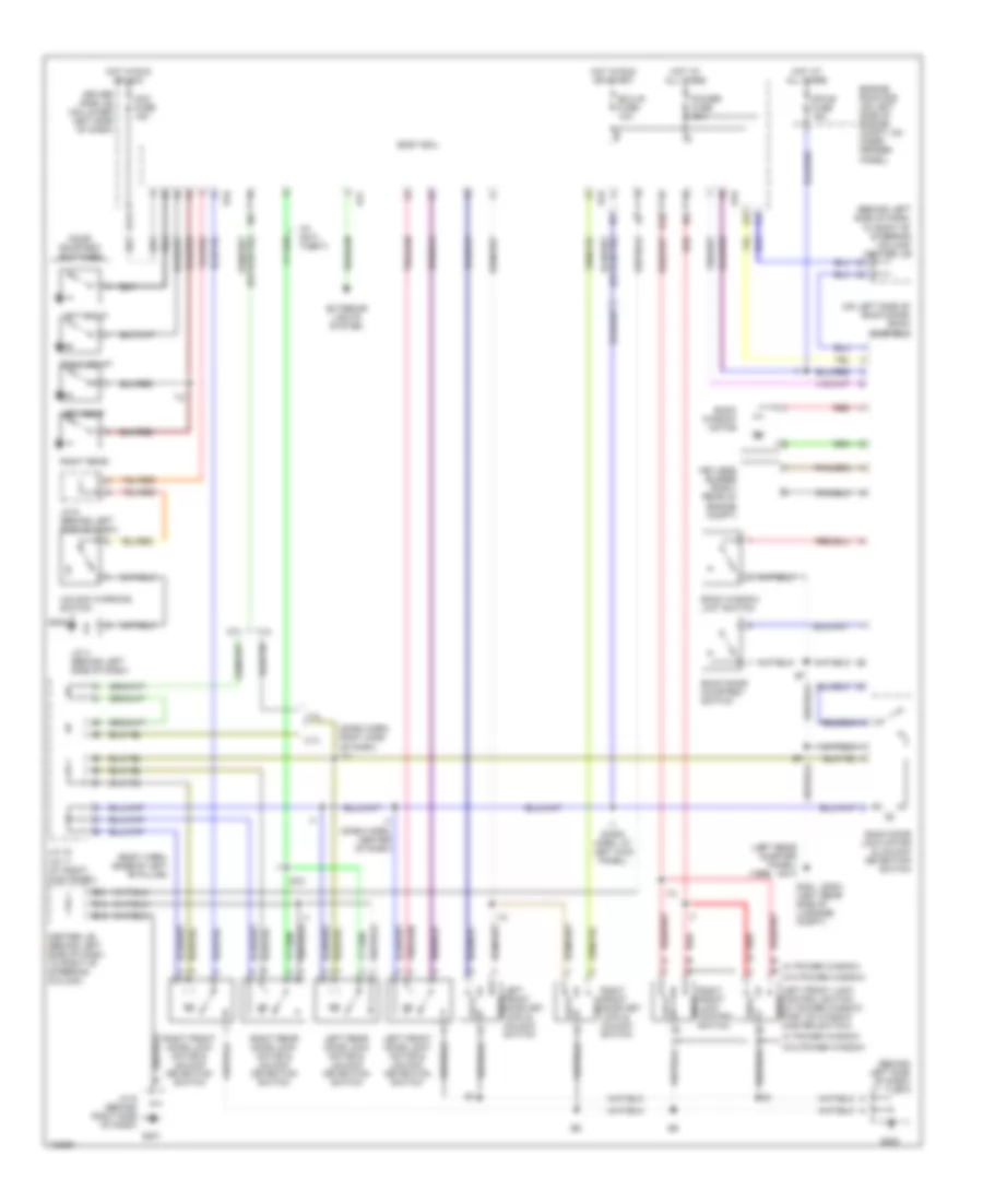
AIR CONDITIONING
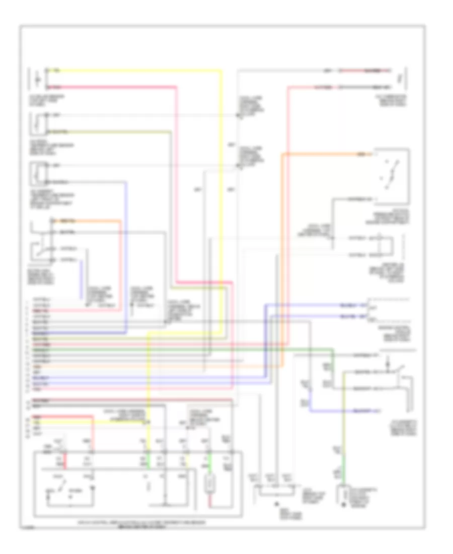
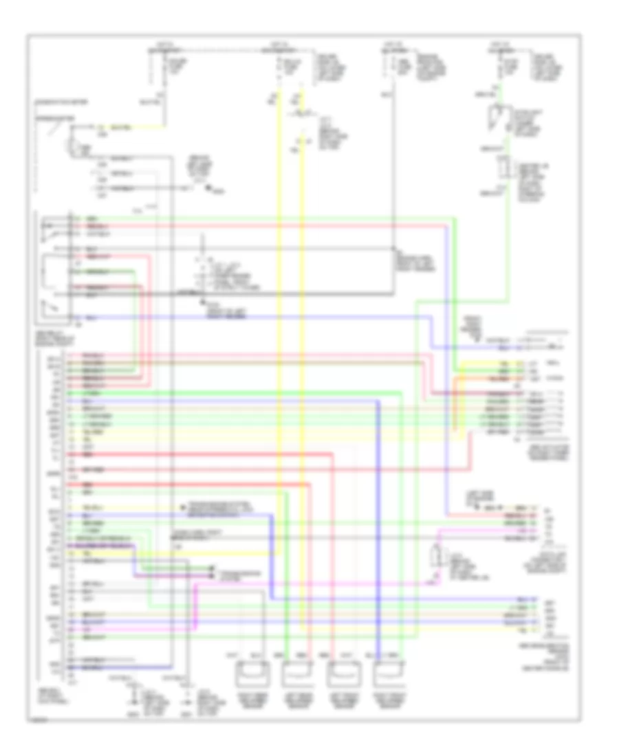
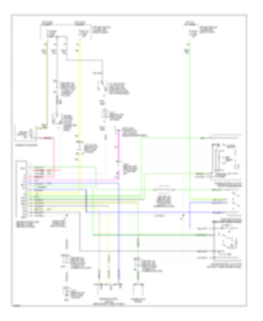
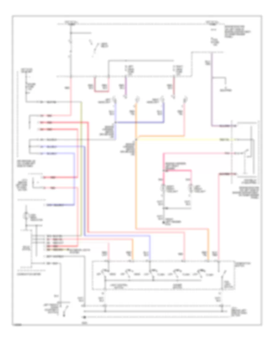
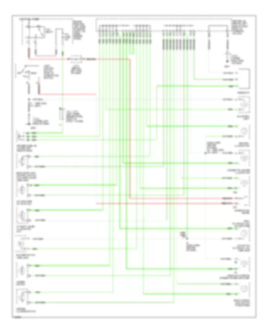
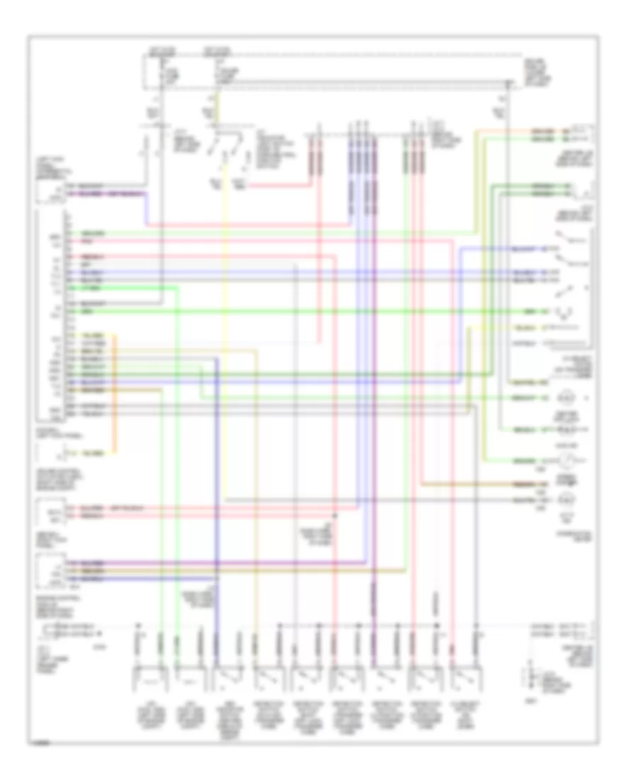
Automatic A/C Wiring Diagram (1 of 2) for Toyota 4Runner 1999
 https://portal-diagnostov.com/license.html
Automotive Electricians Portal FZCO
Automotive Electricians Portal FZCO
https://portal-diagnostov.com/license.html
https://portal-diagnostov.com/license.html
Automotive Electricians Portal FZCO
Automotive Electricians Portal FZCO
List of elements for Automatic A/C Wiring Diagram (1 of 2) for Toyota 4Runner 1999:
- (cowl wire harness, top right side of dash) i19
- (left front fender) g102
- A/c amplifier (behind center of dash)
- A10
- A11
- A12
- A13
- A14
- A15
- A16
- A17
- A18
- A19
- A20
- A21
- A22
- A23
- A24
- A25
- A26
- A30
- A31
- Ac1
- Act
- Aif
- Air
- Air inlet control servo motor (behind right side of dash)
- Air vent mode control servo motor (behind center of dash)
- Amc
- Amh
- B/l
- B10
- B11
- B12
- B13
- B14
- B15
- B16
- Blower motor (behind right side of dash)
- Blower motor linear controller (behind right side of dash)
- Blower resistor (behind right side of dash)
- Blw
- C20
- C22
- Center j/b (behind left side of dash, right of steering column)
- Clk
- Control circuit
- Def
- Dpd
- Driver side j/b (on lower left side of dash)
- Ecu-b fuse 7.5a
- Engine room r/b (on left side of engine compartment, on inner fender panel)
- F/d
- Face
- Foot
- Fresh
- Gauge fuse 10a
- Gnd
- Heater control panel switch
- Heater fuse 50a
- Heater relay
- Hot at all times
- Hot in on or start
- I12 (cowl wire harness, top right side of dash)
- I5 (cowl wire harness, above left side of combination meter)
- I9 (cowl wire harness, right side of steering column)
- Ig+
- Ill+
- Ill-
- Illum
- Instrument cluster system
- Interior lights system
- J/c 1 & 2 (on left inner fender panel, front of strut tower)
- J/c 1 (on left inner fender panel, front of strut tower)
- Mgc
- Motor position switches
- Mfrs
- Mrec
- Pnk
- Psw
- Recirc
- Red
- Spd
- Stx
- Swd
- Tam
- Tpi
- Ver1
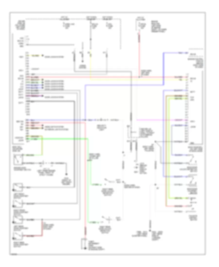
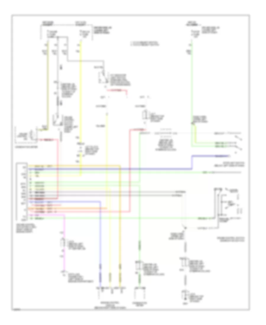
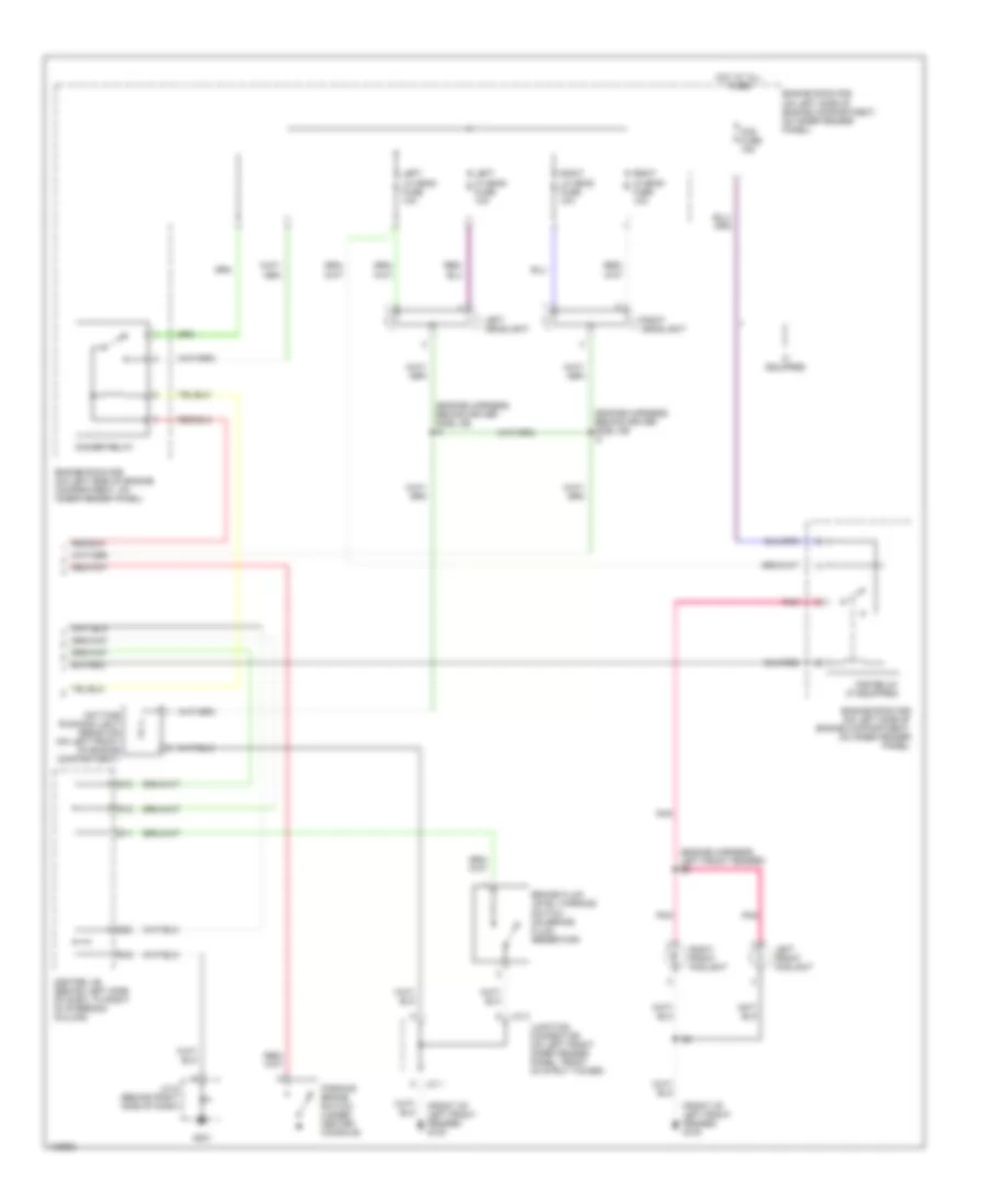
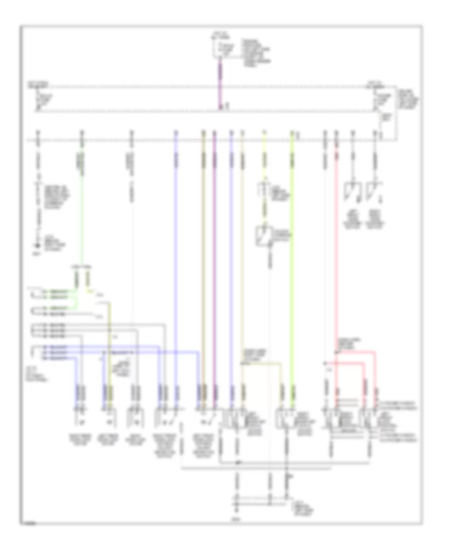
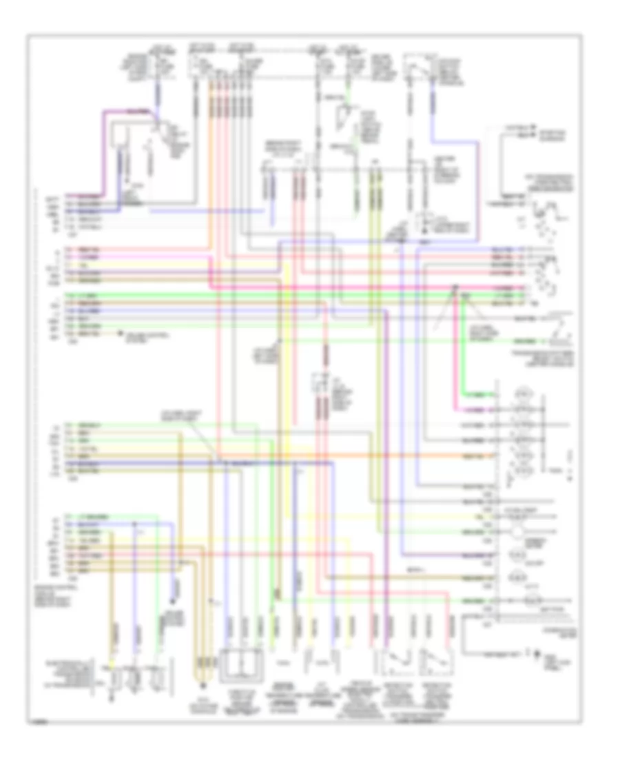
Automatic A/C Wiring Diagram (2 of 2) for Toyota 4Runner 1999
List of elements for Automatic A/C Wiring Diagram (2 of 2) for Toyota 4Runner 1999:
- (cowl wire harness, above left side of combination meter) i5
- (cowl wire harness, behind center of dash) i16
- (cowl wire harness, right side of steering column) i9
- (cowl wire harness, top center of dash) i7
- A/c ambient temperature sensor (left front of engine compartment at grille)
- A/c dual pressure switch (on right rear of engine compartment)
- A/c magnetic clutch (on right front of engine)
- A/c magnetic clutch relay (behind right side of dash)
- A/c room temperature sensor (behind left side of dash)
- A/c solar sensor (top left side of dash)
- A/c thermistor (behind right side of dash)
- Ac1
- Act
- Air mix control servo motor & a/c water temperature sensor (behind center of dash)
- Center j/b (behind left side of dash, to right of steering column)
- Cool
- E16
- E17
- Engine control module (behind right side of dash)
- Extra high speed relay (behind right side of dash)
- G203 (right side kick panel)
- Gnd
- J/c 9 (behind top right side of dash)
- Mcool
- Mhot
- Pnk
- Red
- Warm
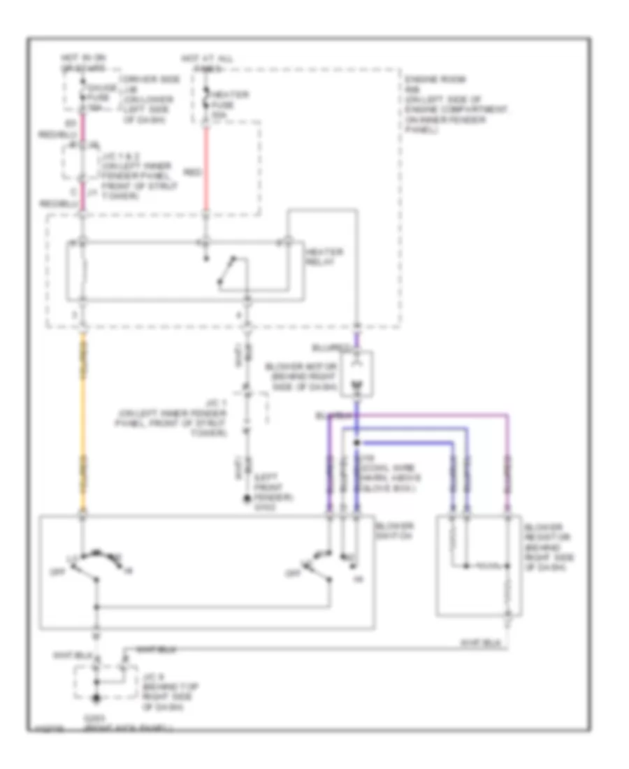
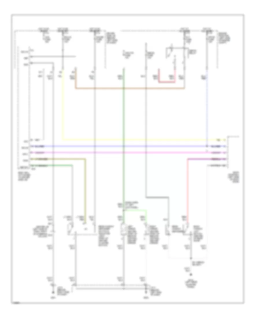
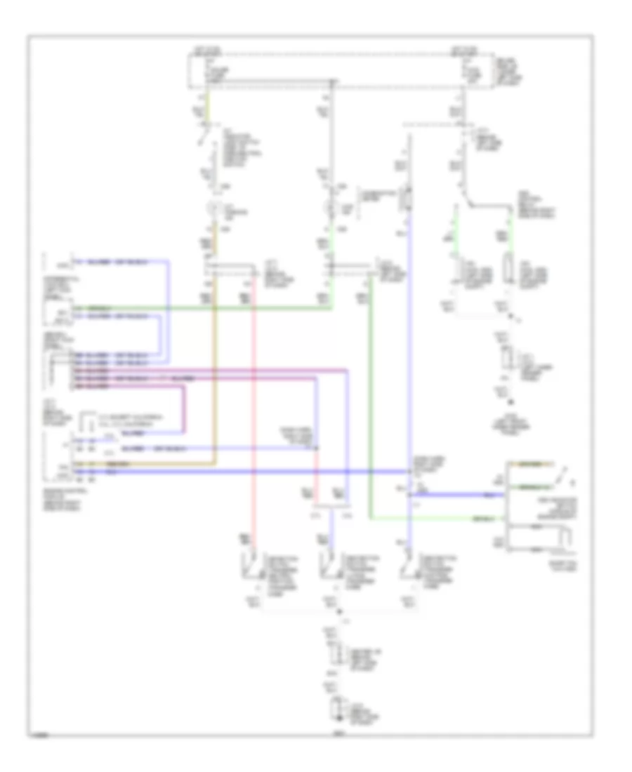
Heater Wiring Diagram for Toyota 4Runner 1999
List of elements for Heater Wiring Diagram for Toyota 4Runner 1999:
- (cowl wire harn, above glove box)
- (left front fender) g102
- Blower motor (behind right side of dash)
- Blower resistor (behind right side of dash)
- Blower switch
- C j1
- Driver side j/b (on lower left side of dash)
- Engine room r/b (on left side of engine compartment, on inner fender panel)
- G203 (right kick panel)
- Gauge fuse 10a
- Heater fuse 50a
- Heater relay
- Hot at all times
- Hot in on or start
- J/c 1 & 2 (on left inner fender panel, front of strut tower)
- J/c 1 (on left inner fender panel, front of strut tower)
- J/c 9 (behind top right side of dash)
- Off
- Red
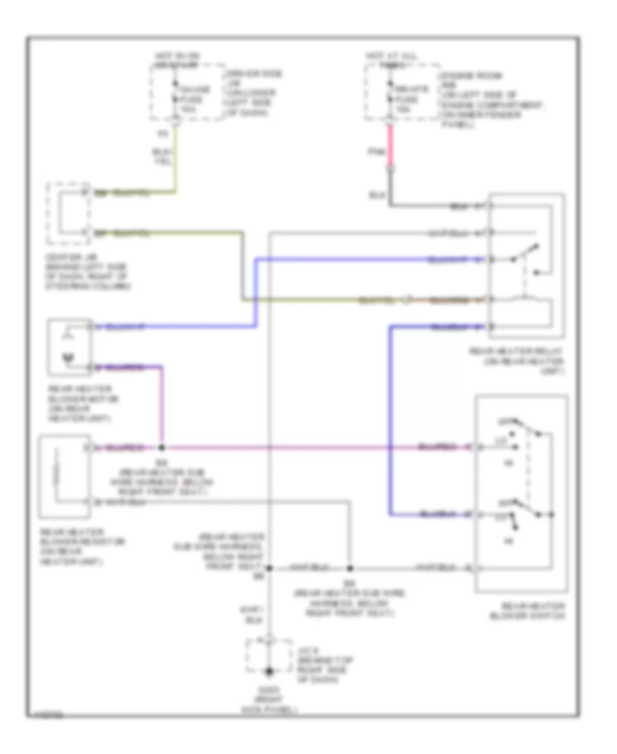
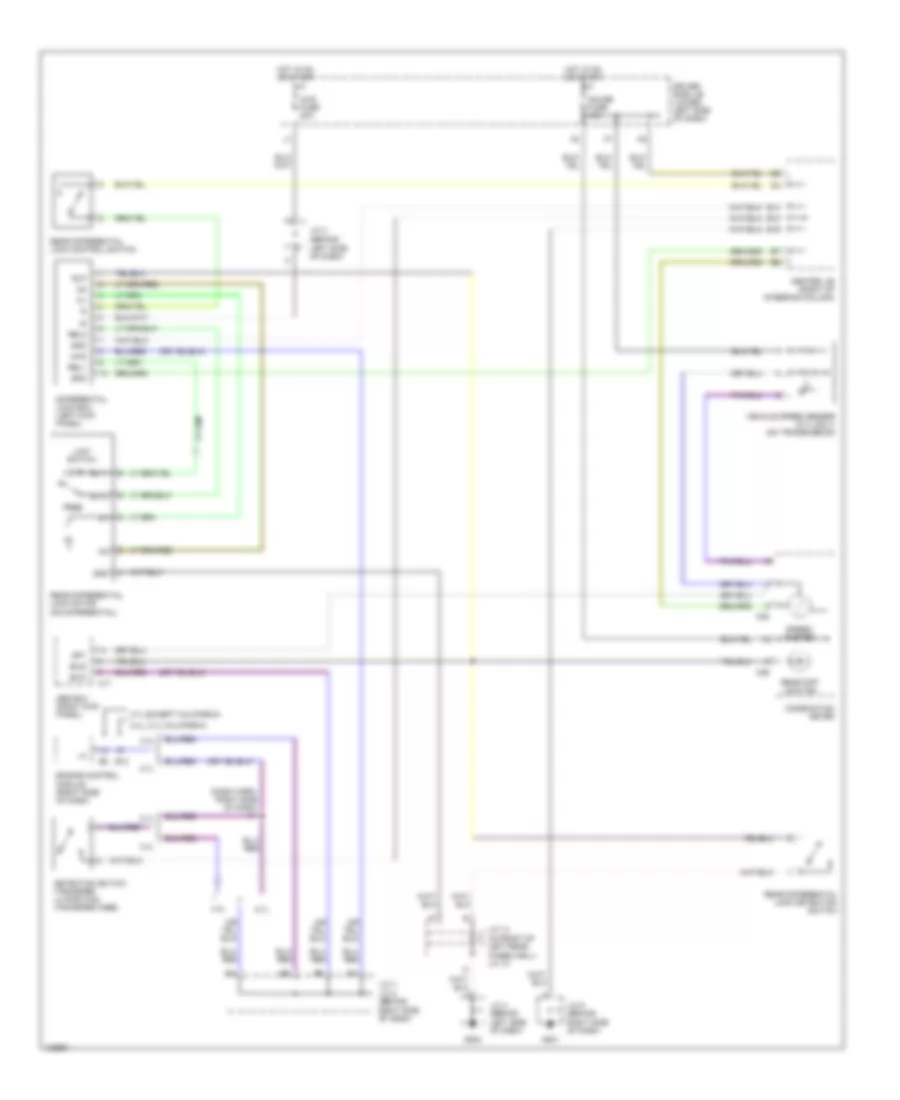
Heater Wiring Diagram, Rear for Toyota 4Runner 1999
List of elements for Heater Wiring Diagram, Rear for Toyota 4Runner 1999:
- (rear heater sub wire harness, below right front seat)
- (rear heater sub wire harness, below right front seat) b8
- 0ff
- Center j/b (behind left side of dash, right of steering column)
- Driver side j/b (on lower left side of dash)
- Engine room r/b (on left side of engine compartment, on inner fender panel)
- G203 (right kick panel)
- Gauge fuse 10a
- Hot at all times
- Hot in on or start
- J/c 9 (behind top right side of dash)
- Pnk
- Rear heater blower motor (on rear heater unit)
- Rear heater blower resistor (on rear heater unit)
- Rear heater blower switch
- Rear heater relay (on rear heater unit)
- Rr htr fuse 10a
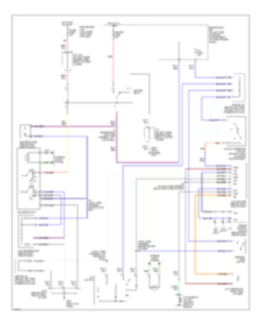
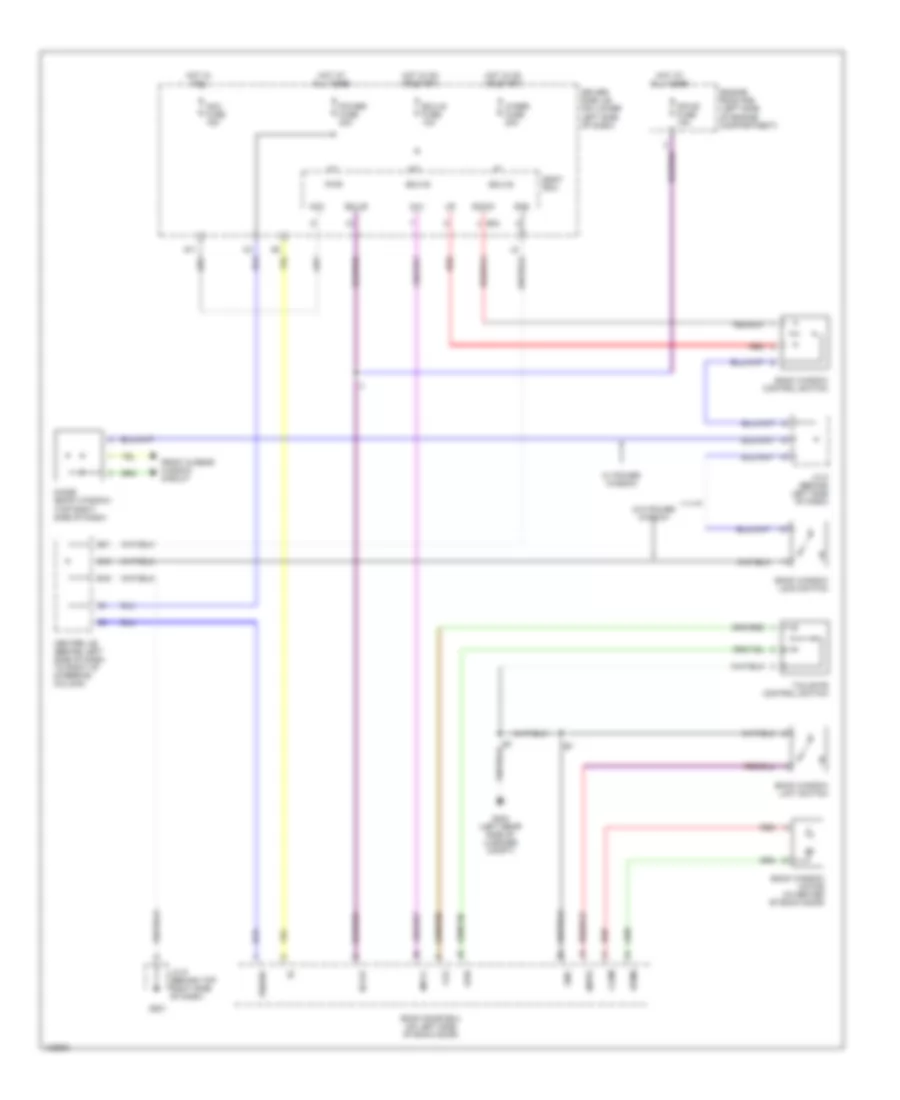
Manual A/C Wiring Diagram for Toyota 4Runner 1999
List of elements for Manual A/C Wiring Diagram for Toyota 4Runner 1999:
- (cowl wire harness, behind center of dash) i9
- (cowl wire harness, top center of dash) i7
- (left front fender) g102
- 2.7l (calif)
- 2.7l (ex calif)
- 3.4l
- A/c
- A/c amplifier (behind right side of dash)
- A/c dual pressure switch (on right rear of engine compartment)
- A/c fuse 10a
- A/c magnetic clutch (on right front of engine)
- A/c switch
- A/c thermistor (right side of dash)
- Ac1
- Act
- B/v
- Blower motor (behind right side of dash)
- Blower resistor (behind right side of dash)
- Blower switch
- Center j/b (behind left side of dash, right of steering column)
- Defrost mode switch
- Driver side j/b (on lower left side of dash)
- E12
- E16
- E17
- Engine control module (behind right side of dash)
- Engine room r/b (on left side of engine compartment, on inner fender panel)
- G203 (right kick panel)
- Gauge fuse 10a
- Gnd
- Heater fuse 50a
- Heater relay
- Hot at all times
- Hot in on or start
- I15 (a/c sub wire harness, below right side of dash)
- I19 (cowl wire harness, above glove box)
- I3 (engine room main wire harness, left kick panel)
- Interior lights system
- J/c 1 & 2 (on left inner fender panel, front of strut tower)
- J/c 1 (on left inner fender panel, front of strut tower)
- J/c 9 (behind right side of dash, on top)
- Mgc
- Off
- Prs
- Red
ANTI-LOCK BRAKES
Anti-lock Brake Wiring Diagrams for Toyota 4Runner 1999
List of elements for Anti-lock Brake Wiring Diagrams for Toyota 4Runner 1999:
- (behind left side of dash, on top) j/c 4
- (dash harn, right end of dash)
- (front right fender) g105
- (left side of engine) g112
- +ig
- +ig1
- 3.4l
- A16
- A17
- Abs actuator (on right inner fender panel)
- Abs deceleration sensor (4wd) (front of center console)
- Abs ecu (at right kick panel)
- Abs fuse 60a
- Abs ind
- Abs relay (right rear of engine compt)
- Ast
- C14
- C15
- C25
- C27
- C28
- C29
- Center j/b (behind left side of dash, right of steering column)
- Combination meter
- D j8
- Data link connector 1 (on left side of engine compt)
- Driver side j/b (on lower left side of dash)
- E j7
- E3 (engine harn, front of left front fender)
- Ecu-ig fuse 10a
- Engine room r/b (left side of engine compt)
- Exi
- Exi 3
- Exi2
- Fl+
- Fl-
- Fr+
- Fr-
- G10o (front of left front fender)
- G201
- G202
- Gauge fuse 10a
- Ggnd
- Gnd
- Gs1
- Gs2
- Gst
- Hot at all times
- Hot in on or start
- I20
- J/c 1, j/c 2 (on left inner fender panel, front of strut tower)
- J/c 4 (behind left side of dash, on top)
- J/c 6 (behind left side of dash, at center j/b)
- J/c 7, j/c 8 (behind right side of dash, on top)
- J/c 9 (behind right side of dash, on top)
- Left front abs speed sensor
- Left rear abs speed sensor
- Red
- Right front abs speed sensor
- Right rear abs speed sensor
- Rl+
- Rl-
- Rr+
- Rr-
- Sflh
- Sflr
- Sfrh
- Sfrr
- Sp1
- Speedometer
- Srh
- Srr
- Stop fuse 10a
- Stoplight switch (under left side of dash)
- Stp
- Transmissions system
- Transmissions system (rear differential lock detection switch)
ANTI-THEFT
Forced Entry Wiring Diagram for Toyota 4Runner 1999
List of elements for Forced Entry Wiring Diagram for Toyota 4Runner 1999:
- (1999)
- (2000)
- (body harn, lower left "b" pillar) b10
- (dash harn, left end of dash) i1
- A10
- A11
- A12
- A13
- A14
- A15
- A16
- A17
- A18
- A19
- A20
- A21
- A22
- A23
- Acc
- Acc fuse 15a
- B16
- B17
- B7 (body harn, left rear tailgate)
- Back door courtesy switch
- Back door ecu (on left side of back door)
- Back door unlock detection switch
- Bcty
- Body ecu (on driver side j/b)
- Center j/b (left side of dash, to right of steering column)
- Cls
- Dcty
- Door locks system
- Down
- Driver side j/b (on lower left side of dash)
- E13
- E16
- E21
- Ecu-b
- Ecu-ig
- Ecu-ig fuse 10a
- Engine control module (behind right side of dash)
- Engine hood courtesy switch
- Engine room r/b (left side of engine compt, on inner fender panel)
- Exterior lights system
- G100 (front of left front fender)
- G11
- G201
- G404 (left rear side of luggage compt)
- G414 (left rear quarter panel)
- Grd
- Haz
- Headlights system
- Hood sw
- Horn
- Horn, haz. fuse 15a
- Horns system
- Hot at all times
- Hot in run or start
- Hry
- I12 (dash harn, right end of dash)
- I7 (dash harn, center of dash)
- J/c 1, 2 (left inner fender panel, front of strut tower)
- J/c 9 (behind right side of dash, on top)
- Ksw
- Left front door courtesy switch
- Left rear door courtesy switch
- Lswb
- Lswd
- Lswp
- Lswr
- Mpx-b fuse 15a
- Mpx1
- Opn
- Pcty
- Rcty
- Red
- Right front door courtesy switch
- Right rear door courtesy switch
- Right rear door unlock detection switch
- Sec ind
- Security indicator light
- Tailgate control switch
- Theft deterrent horn (on right side of engine compt)
- Try
- Ul2
- Ul3
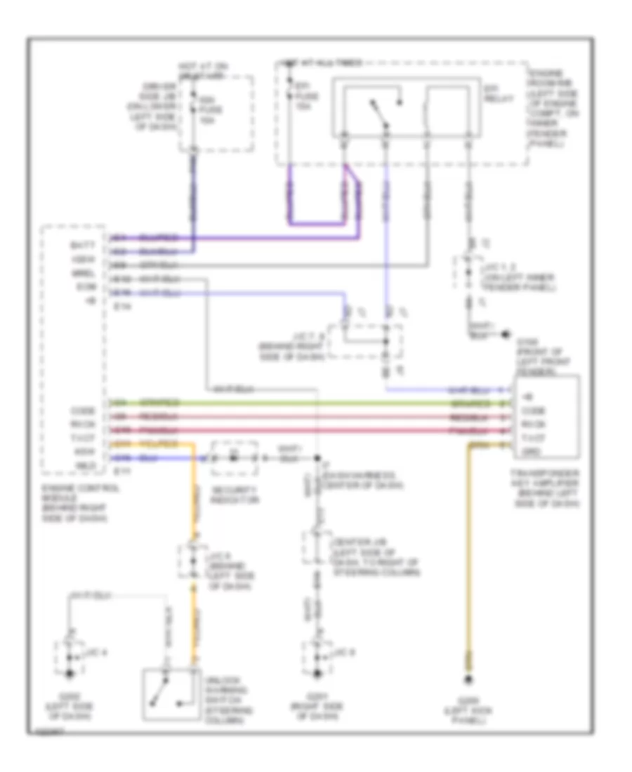
Immobilizer Wiring Diagram for Toyota 4Runner 1999
List of elements for Immobilizer Wiring Diagram for Toyota 4Runner 1999:
- Batt
- C10
- C11
- C16
- Center j/b (left side of dash, to right of steering column)
- Code
- E11
- E12
- E13
- E14
- E16
- Efi fuse 15a
- Efi relay
- Engine control module (behind right side of dash)
- Engine room r/b (left side of engine compt, on inner fender panel)
- Eom
- F10
- G100 (front of left front fender)
- G200 (left kick panel)
- G201 (right side of dash)
- G202 (left side of dash)
- Grd
- Hot at all times
- Hot at on or start driver side j/b (on lower left side of dash)
- Ign fuse 10a
- Igsw
- Imld
- J/c 1, 2 (on left inner fender panel)
- J/c 4
- J/c 6 (behind left side of dash)
- J/c 7, 8 (behind right side of dash)
- J/c 9
- Ksw
- Mrel
- Rxck
- Security indicator
- Transponder key amplifier (behind left side of dash)
- Txct
- Unlock warning switch (steering column)
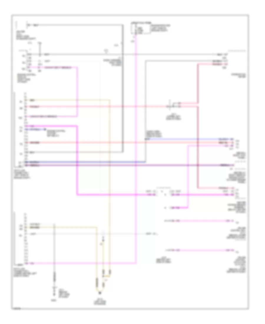
COMPUTER DATA LINES
Computer Data Lines for Toyota 4Runner 1999
List of elements for Computer Data Lines for Toyota 4Runner 1999:
- (dash harn, behind right side of dash) i20
- 2.7l
- 3.4l
- A17
- Abs ecu (right kick panel)
- Abs relay (right rear of engine compt, on inner fender panel)
- Bat
- C25
- C28
- Center air bag sensor assembly (below center of dash)
- Combination meter
- Cruise control actuator with ecu (3.4l) (behind lower center of dash)
- Cruise control ecu (2.7l) (behind lower center of dash)
- Data link connector 1 (left side of engine compt)
- Data link connector 3 (under center left side of dash)
- E14
- Engine control module (right side of dash)
- Engine control system (efi relay)
- Engine room r/b (left side of engine compt)
- G112 (left side of engine)
- G202
- Hot at all times
- I11
- I11 (dash harness, right side of dash)
- Ig-
- Igniter (3.4l) (right side of engine compt)
- J/c 3 (upper left side of dash)
- J/c 4 (behind left side of dash)
- J/c 6 (behind left side of dash)
- Obd fuse 7.5a
- Sil
- Te1
CRUISE CONTROL
2.7L
2.7L, Cruise Control Wiring Diagram for Toyota 4Runner 1999
List of elements for 2.7L, Cruise Control Wiring Diagram for Toyota 4Runner 1999:
- (a/t)
- (m/t)
- A/t indicator light switch (park/neutral position switch) (on transmission)
- A21
- Ae j7
- Bd j8
- C13
- C15
- C28
- Cancel
- Ccs
- Center j/b (behind left side of dash, to right of steering column)
- Cms
- Combination meter
- Cruise
- Cruise control actuator (on right inner fender panel)
- Cruise control clutch switch (under left side of dash)
- Cruise control ecu (behind lower center of dash)
- Cruise control ind
- Cruise control switch (combination switch)
- D18
- Data link connector 1 (left side of engine compartment)
- Driver side j/b (lower left side of dash)
- E12
- E16
- Ect
- Ecu-ig fuse 10a
- Engine control module (behind right side of dash)
- G201
- Gauge fuse 10a
- Gnd
- Hot at all times
- Hot in on & start
- I6 (dash harn, upper left side of dash)
- Idl
- Idlo
- J/c 6 (behind left side of dash, at center j/b)
- J/c 7 & j/c 8 (behind top right side of dash)
- J/c 7 (behind top right side of dash)
- J/c 9 (behind top right side of dash)
- Od1
- Resume/ accel
- Set/ coast
- Spd
- Stop fuse 10a
- Stoplight switch (below left side of dash)
- Stp-
3.4L
3.4L, Cruise Control Wiring Diagram for Toyota 4Runner 1999
List of elements for 3.4L, Cruise Control Wiring Diagram for Toyota 4Runner 1999:
- (a/t)
- (dash harn, upper left end of dash) i2
- (m/t)
- A/t indicator light switch (park/neutral position switch) (on transmission)
- Ae j7
- Bd j8
- C13
- C15
- C28
- Cancel
- Ccs
- Center j/b (behind left side of dash, to right of steering column)
- Cms
- Combination meter
- Cruise
- Cruise control actuator w/ ecu (right side of engine compt)
- Cruise control clutch switch (under left side of dash)
- Cruise control ind
- Cruise control switch (combination switch)
- D24
- Data link connector 1 (left side of engine compartment)
- Driver side j/b (lower left side of dash)
- Driver side j/b driver side j/b (lower left (lower left side of dash) side of dash)
- E12
- E16
- Ect
- Ecu-ig fuse 10a
- Engine control module (behind right side of dash)
- G201
- Gauge fuse 10a
- Gnd
- Hot at hot at all times all times
- Hot in on & start
- Hot in on hot in on & start & start
- I6 (dash harn, upper left side of dash)
- Idl
- Idlo
- J/c 6 (behind left side of dash, at center j/b)
- J/c 7 & j/c 8 (behind top right side of dash)
- J/c 7 (behind top right side of dash)
- J/c 9 (behind top right side of dash)
- Od1
- Resume/ accel
- Set/ coast
- Spd
- Stop fuse 10a
- Stoplight switch (below left side of dash)
- Stp-
- W/ 2-4 select switch w/o 2-4 select switch
DEFOGGERS
Defogger Wiring Diagram for Toyota 4Runner 1999
List of elements for Defogger Wiring Diagram for Toyota 4Runner 1999:
- (1999-00) (2001)
- (dash harn, at left kick panel) i1
- (left side of dash, right of steering column)
- Acc
- Acc fuse 15a
- Alt fuse 120a
- B16
- B7 b9
- Back door ecu (left side of back door)
- Back window limit switch (center of rear door)
- Body ecu (attached to driver side j/b)
- Center j/b
- Def
- Def sw
- Defog fuse 15a
- Defog relay
- Dind
- Driver side j/b (behind left side of dash)
- E16
- E21
- Ecu-b
- Ecu-ig
- Ecu-ig fuse 10a
- Engine room r/b (left side of engine compt)
- G11
- G201
- G202
- G414 (left rear quarter panel)
- Gauge fuse 10a
- Gnd
- Hot at all times
- Hot in on or acc
- Hot in on or start
- J/c 4 (behind left side of dash)
- J/c 9 (behind right side of dash)
- Left mirror heater (part of remote control center mirror)
- Mir htr fuse 10a
- Mpx-b fuse 15a
- Mpx1
- Rear window defogger
- Rear window defogger switch & indicator light (part of center cluster switch)
- Right mirror heater (part of remote control center mirror)
ENGINE PERFORMANCE
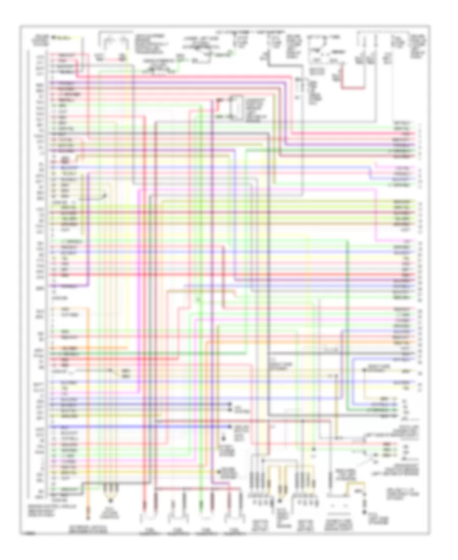
2.7L
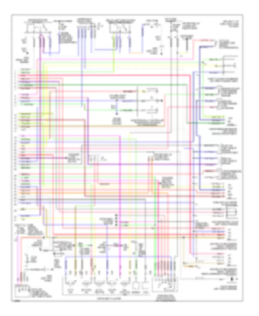
2.7L, Engine Performance Wiring Diagrams (1 of 2) for Toyota 4Runner 1999
List of elements for 2.7L, Engine Performance Wiring Diagrams (1 of 2) for Toyota 4Runner 1999:
- (eng harn, top left of engine)
- (near steering column) center j/b
- (right side of dash)
- (splice i11: i/p harn right side of dash)
- (under left side of dash) stoplight switch
- 4wd
- A/c system
- Ac1
- Acc
- Act
- Add ind switch (4wd only)
- Atf
- Batt
- C11
- C15
- Camshaft position sensor (left center of engine)
- Cen- ter j/b (near steer col)
- Conn e5
- Conn e6
- Conn e7
- Conn e8
- Crankshaft position sensor (left center of engine)
- Cruise control system
- Data link connector 1 (left side of engine compt)
- Driver side j/b (lower left side of dash)
- E01
- E02
- E03
- Egr
- Els
- Engine control module (behind right side of dash)
- Evp
- Exterior lights & defogger systems
- Fuel injector 1
- Fuel injector 2
- Fuel injector 3
- Fuel injector 4
- G112 (left side of engine)
- G119 (right front of engine)
- G131 (intake manifold)
- Gnd
- Hot at all times
- Hot in start
- Ht1
- Ht2
- I11
- I11 (right side of dash)
- Ig-
- Igf
- Ign fuse 7.5a
- Ignition coil 1 & ignitor 1
- Ignition coil 2 & ignitor 2
- Ignition switch
- Igt
- Igt1
- Igt2
- Inj1
- Inj2
- Inj3
- Inj4
- Knk
- Lock
- Ne-
- Noise filter (right side of engine compt)
- Nsw
- Od1
- Od2
- Oil
- Oil-w
- Ox1
- Ox2
- Pnk
- Ptnk
- Pwr
- Red
- Rsc
- Rso
- Run
- Sdl
- Sp1
- Sp2+
- Sp2-
- Sta
- Sta fuse 7.5a
- Start
- Start/ charge system
- Stop fuse 10a
- Tach
- Te1
- Tfn
- Thg
- Thw
- Tpc
- Vcc
- Vehicle speed sensor (electronically controlled transmission)
- Vta
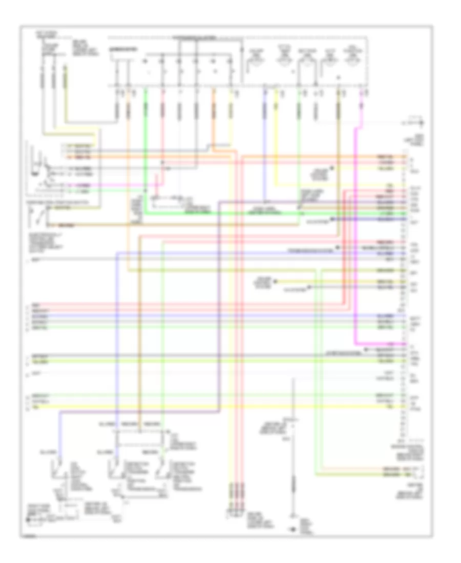
2.7L, Engine Performance Wiring Diagrams (2 of 2) for Toyota 4Runner 1999
List of elements for 2.7L, Engine Performance Wiring Diagrams (2 of 2) for Toyota 4Runner 1999:
- (below left side of dash) circuit opening relay
- (engine room r/b) efi relay
- (i/p harn, center of dash)
- (i/p harn, left side of dash)
- (i/p harn, right side of dash) i11
- (left side of engine compartment)
- (splice i11: i/p harn, right side
- (upper right side of dash)
- A/t fluid temperature sensor (in transmission)
- A/t oil temp ind
- A/t p ind
- Bat
- C25
- C26
- C27
- C28
- C29
- Cen- ter j/b (near steer col)
- Cruise control system
- Data link connector 3 (under center left side of dash)
- Driver side j/b (lower left side of dash)
- E10
- E2g
- Ect pwr ind
- Efi fuse 20a
- Egr gas temp sensor (top of engine)
- Egr vsv (left side of engine)
- Electronically controlled trans pattern select sw
- Electronically controlled transmission solenoid (on transmission)
- Engine coolant temp sensor (top rear of engine)
- Engine room r/b (left side of engine compt)
- Evap vsv (left side of engine compartment)
- Fuel pump
- G100 (front left fender)
- G131 (intake manifold)
- G200 (left kick panel)
- G202 (left kick panel)
- Gauge fuse 10a
- Heated oxygen sensor (bank 1 sensor 1) (rear underside of eng compt)
- Heated oxygen sensor (bank 1 sensor 2) (underside of vehicle)
- Hot at all times
- Hot in run or start
- I11
- I19
- I19 (dash harn, upper right of dash)
- Idle air control valve (left side of engine)
- Instrument cluster
- Instrument cluster system
- J/c j6 (left dash)
- J/c j7, j8
- Knock sensor (left side of engine)
- Mal- function ind
- Mass air flow meter (in air intake)
- Nca
- O/d main sw
- O/d off ind
- Obd fuse 7.5a
- Of dash)
- Park/neutral position switch (on transmission)
- Pnk
- Ptnk
- Red
- Sdl
- Speedo
- Tach
- Tha
- Throttle position sensor (on throttle body assy)
- Transfer l4 pos detection switch
- Transfer neutral position detection switch
- Vapor pressure sensor (left side of engine compartment)
- Vapor pressure sensor vsv (left side of engine compt)
- Vcc
3.4L
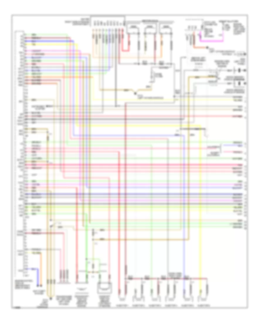
3.4L, Engine Performance Wiring Diagrams (1 of 4) for Toyota 4Runner 1999
List of elements for 3.4L, Engine Performance Wiring Diagrams (1 of 4) for Toyota 4Runner 1999:
- (behind left side of dash)
- (dash harn, right side of dash)
- (engine harn, center of engine)
- Af1-
- Anti-theft system
- California
- Camshaft position sensor (top front of engine)
- Code
- Crankshaft position sensor (front of engine)
- Data link connector (below center left of dash)
- E01
- E02
- E03
- E05
- E10
- E11
- E2g
- Engine control module (behind right side of dash)
- Engine room r/b (left side of engine compt)
- Evp1
- Except california
- Ext
- G112 (left intake manifold)
- G131 (left intake manifold)
- G200 (left kick panel)
- Gnd
- Hot at all times
- I11
- Igc1
- Igc2
- Igc3
- Igf
- Igniter (right side of engine compartment)
- Ignition coils
- Igt1
- Igt2
- Igt3
- Imld
- Injector 1
- Injector 2
- Injector 3
- Injector 4
- Injector 5
- Injector 6
- Instrument cluster
- J/c 6
- Knk1
- Knk2
- Knock sensor 1 (middle of engine)
- Knock sensor 2 (middle of engine)
- Ksw
- Nca
- Ne+
- Ne-
- Noise filter
- Obd fuse 7.5a
- Oil
- Ox1
- Pnk
- Psw
- Red
- Rsc
- Rso
- Rxck
- Sdl
- Shield
- Sil
- Sp2+
- Sp2-
- Te1
- Tha
- Thw
- Transponder key amplifier (left side of dash)
- Txct
- Vta
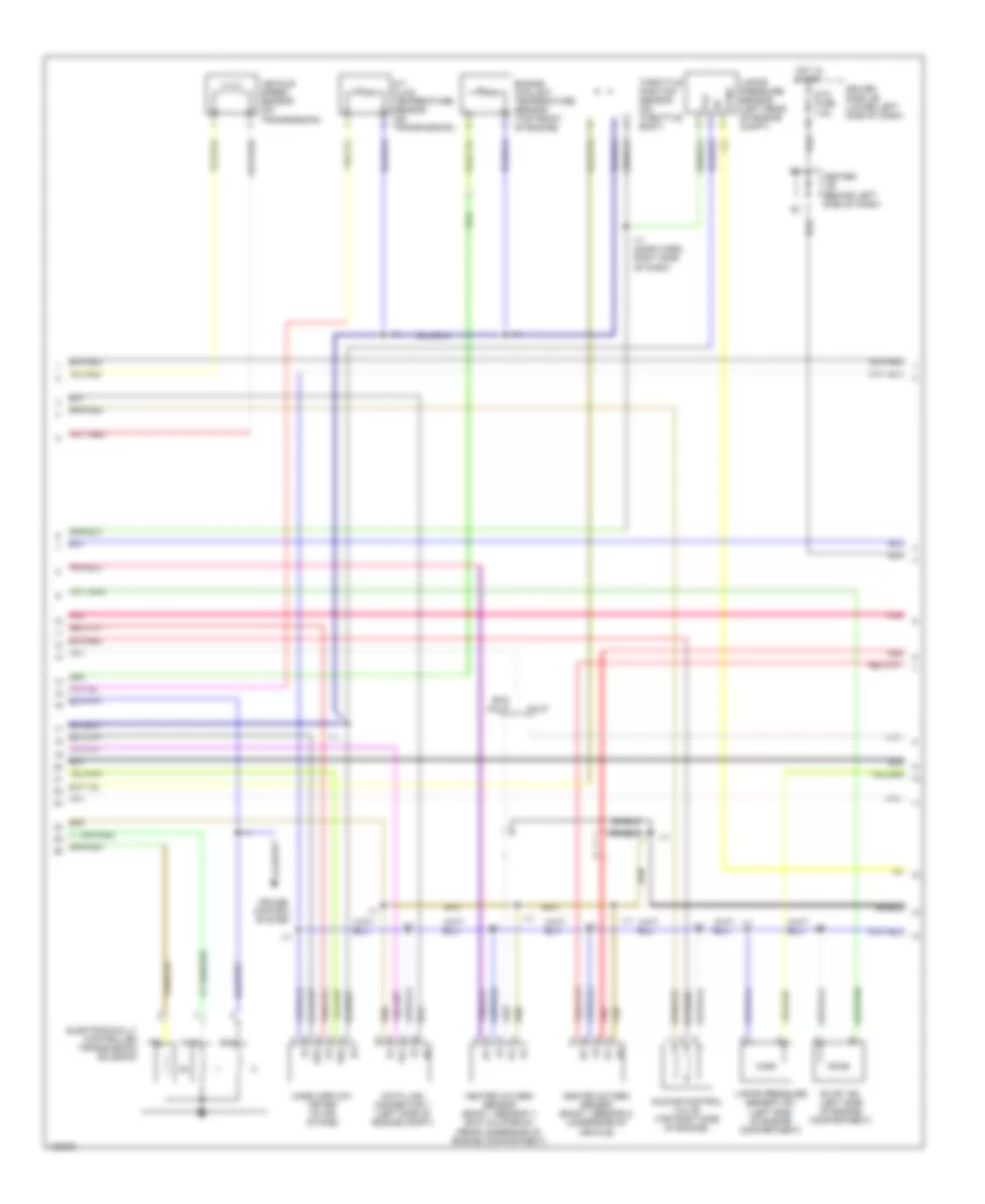
3.4L, Engine Performance Wiring Diagrams (2 of 4) for Toyota 4Runner 1999
List of elements for 3.4L, Engine Performance Wiring Diagrams (2 of 4) for Toyota 4Runner 1999:
- A/t fluid temperature sensor (on transmission)
- Calif
- Center j/b (behind left side of dash)
- Cruise control system
- Data link connector 1 (left side of engine compt)
- Driver side j/b (lower left side of dash)
- E2g
- Electronically controlled transmission solenoid
- Engine coolant temperature sensor (top front of engine)
- Evap vsv (left side of engine compartment)
- Exc calif
- Heated oxygen sensor (bank 1 sensor 1) (exc california) (rear underside of engine compartment)
- Heated oxygen sensor (bank 1 sensor 2) (underside of vehicle)
- Hot in start
- I11
- I11 (dash harn, right side of dash)
- Idle air control valve (top right side of engine)
- Ig-
- Mass airflow meter (in air intake)
- Pnk
- Ptnk
- Red
- Shield
- Sta fuse 7.5a
- Te1
- Tha
- Throttle position sensor (on throttle body)
- Vapor pressure sensor (left rear of engine compt)
- Vapor pressure sensor vsv (left side of engine compartment)
- Vcc
- Vehicle speed sensor (on transmission)
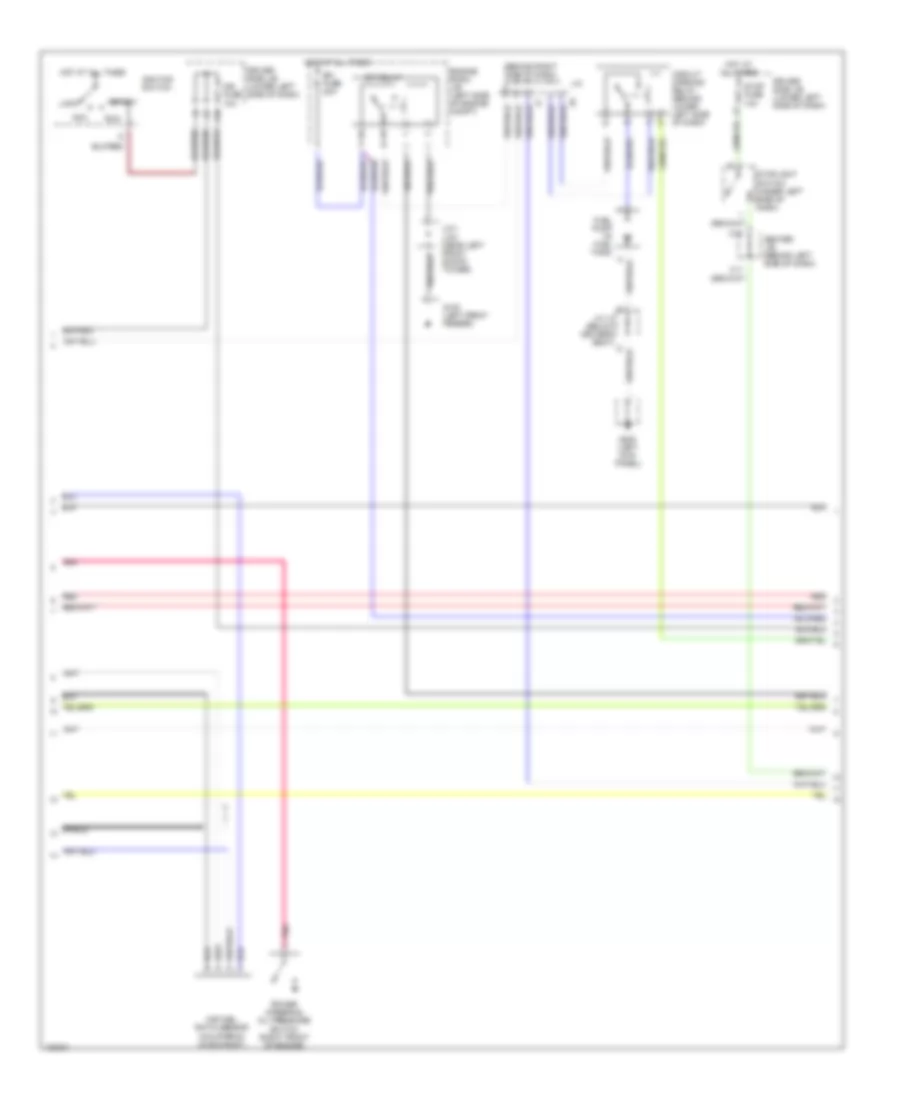
3.4L, Engine Performance Wiring Diagrams (3 of 4) for Toyota 4Runner 1999
List of elements for 3.4L, Engine Performance Wiring Diagrams (3 of 4) for Toyota 4Runner 1999:
- (behind right side of dash)
- Acc
- Air fuel ratio sensor (california) (in exhaust)
- C11
- C15
- Center j/b (behind left side of dash)
- Circuit opening relay (behind lower left side of dash)
- Driver side j/b (lower left side of dash)
- Efi fuse 20a
- Efi relay
- Engine room j/b (left side of engine compt)
- F10
- Fuel pump (in fuel tank)
- G100 (left front fender)
- G200 (left kick panel)
- Hot at all times
- Ign fuse 10a
- Ignition switch
- J/c
- J/c 12 (below driver's seat)
- J/c1, j/c2 (near left front shock tower)
- Lock
- Pnk
- Power steering oil pressure switch (right front of engine)
- Red
- Run
- Shield
- Start
- Stop fuse 10a
- Stoplight switch (under left side of dash)
3.4L, Engine Performance Wiring Diagrams (4 of 4) for Toyota 4Runner 1999
List of elements for 3.4L, Engine Performance Wiring Diagrams (4 of 4) for Toyota 4Runner 1999:
- (dash harn, center of dash)
- (dash harn, left side of dash)
- (right side kick panel) g203
- 4wd
- A/c system
- A/t oil temp ind
- A/t p ind
- Ac1
- Act
- Batt
- C25
- C26
- C27
- C28
- C29
- Center j/b (behind left side of dash)
- Cruise control system
- Detection switch (transfer l4 position) (on transmission)
- Detection switch (transfer neutral position) (on transmission)
- Driver side j/b (lower left side of dash)
- E10
- E12
- E13
- E14
- E16
- E18
- Ect pwr ind
- Electronically controlled transmision pattern select switch
- Engine control module (behind right side of dash)
- Eom
- G200 (left kick panel)
- G203 (right kick panel)
- Gauge fuse 10a
- Hot in run or start
- Hts
- I11
- I19
- I19 (dash harn, right side of dash)
- Idlo
- Igsw
- Instrument cluster
- J/c7, j/c8 (upper right side of dash)
- Mal- function ind
- Mrel
- Nsw
- O/d main switch (shift lock control computer)
- O/d off ind
- Od1
- Od2
- Oil-w
- Oxs
- Park/neutral position switch
- Ptnk
- Pwr
- Red
- Sil
- Sp1
- Speedometer
- Sta
- Starting system
- Stp
- Tfn
- Tpc
- Transmissions system
EXTERIOR LIGHTS
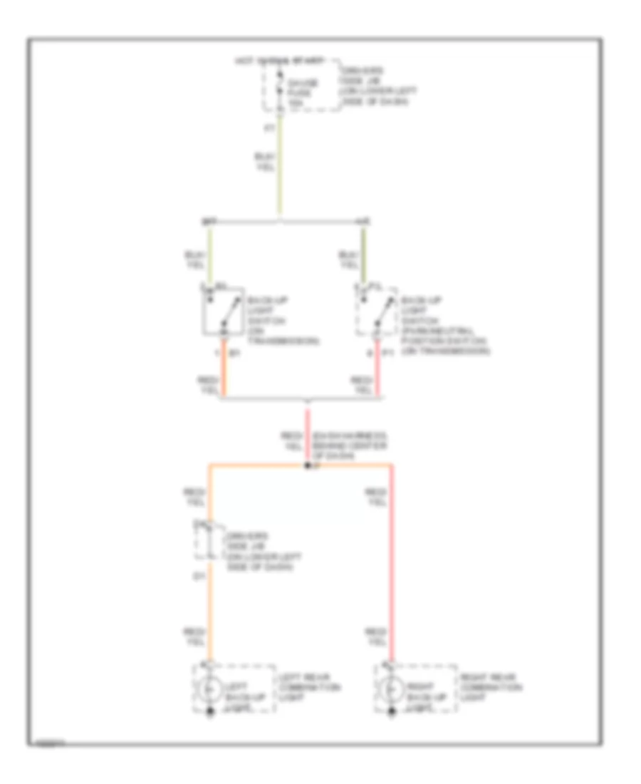
Back-up Lamps Wiring Diagram for Toyota 4Runner 1999
List of elements for Back-up Lamps Wiring Diagram for Toyota 4Runner 1999:
- A/t
- Back-up light switch (on transmission)
- Back-up light switch (park/neutral position switch) (on transmission)
- Behind center of dash) i7
- Driver's side j/b (on lower left side of dash)
- Gauge fuse 10a
- Hot in on & start
- Left back-up light
- Left rear combination light
- M/t
- Right back-up light
- Right rear combination light
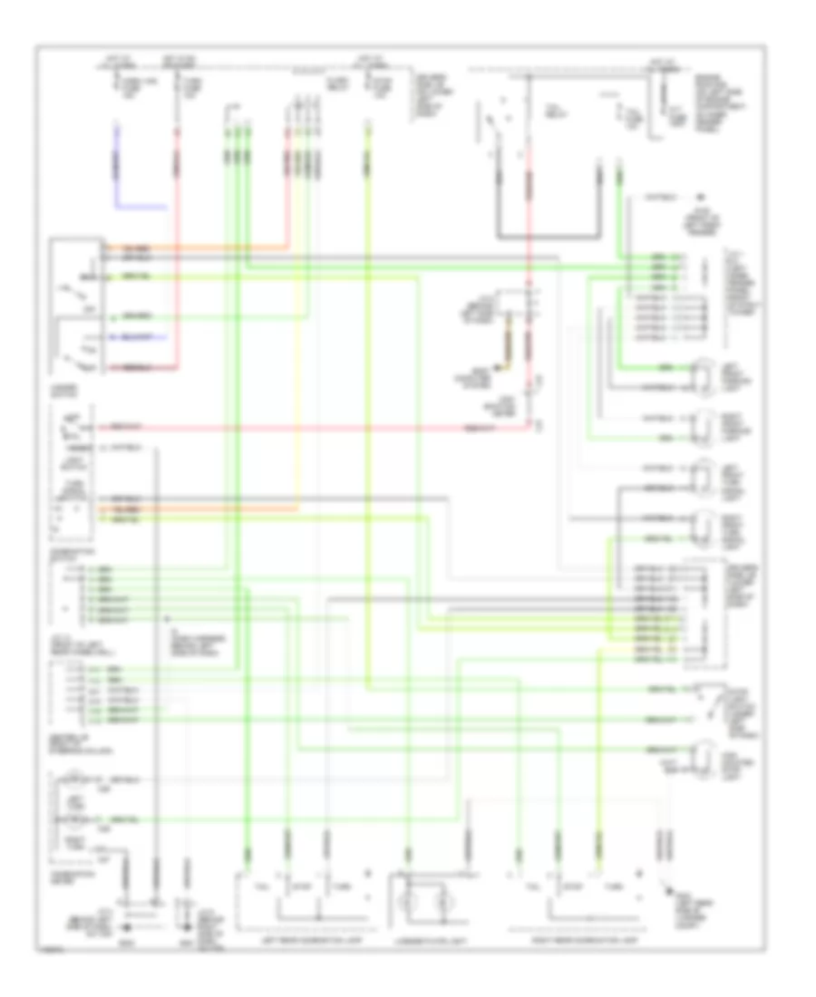
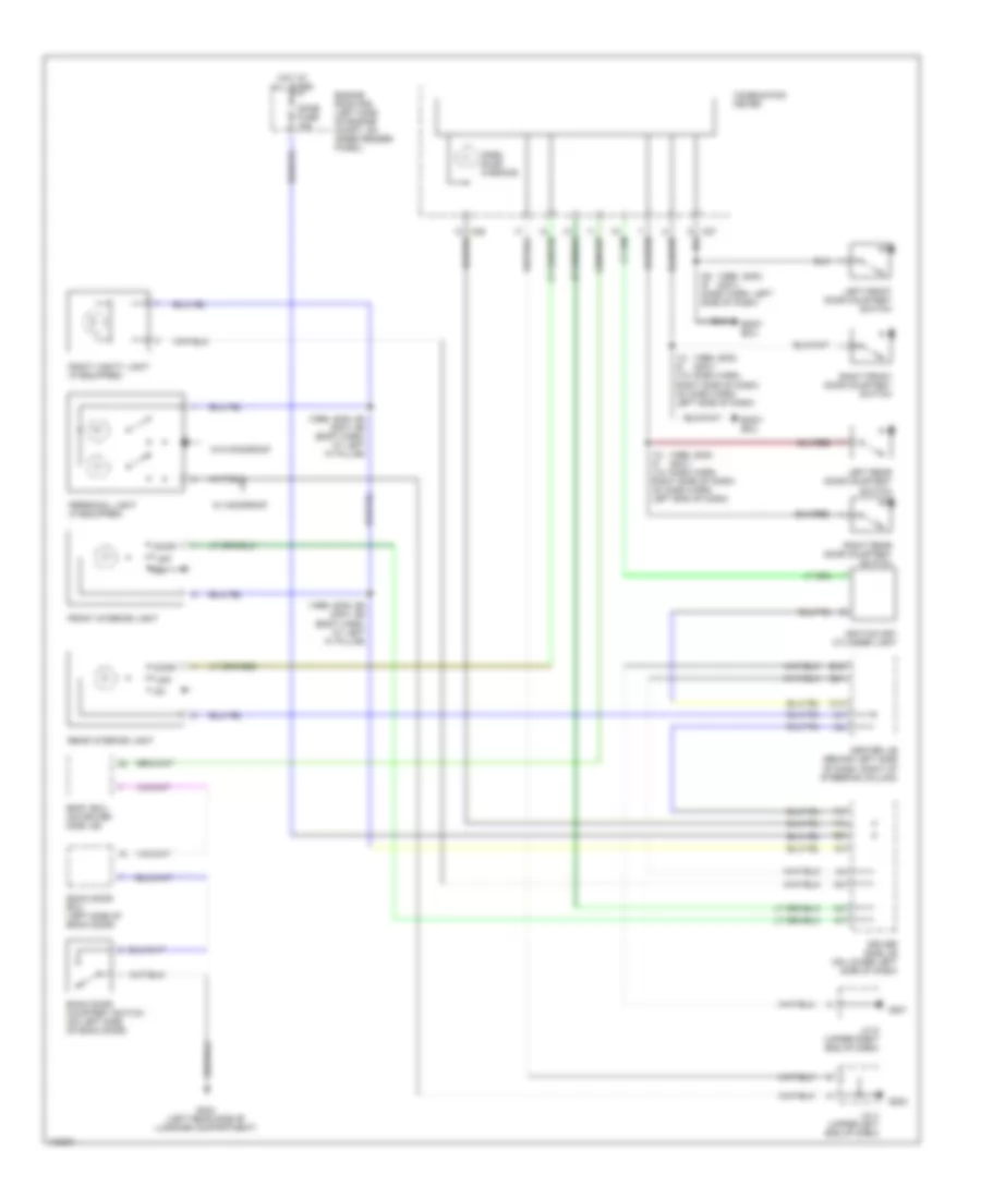
Exterior Lamps Wiring Diagram for Toyota 4Runner 1999
List of elements for Exterior Lamps Wiring Diagram for Toyota 4Runner 1999:
- Alt fuse 120a
- Body computer system
- C15
- C16
- C27
- C29
- Center j/b (right of steering column)
- Com- bination meter
- Combination meter
- Combination switch
- D10
- D11
- Driver's side j/b (lower left side of dash)
- Driver's side j/b (on lower left side of dash)
- E11
- E16
- E21
- Engine room r/b (on left side of engine compartment, on inner fender panel)
- F13
- F17
- Flash relay
- G100 (front of left front fender)
- G201
- G202
- G404 (left rear side of luggage compt)
- H12
- H13
- Hazard switch
- Head
- High mounted stop- light
- Horn, haz fuse 15a
- Hot at all times
- Hot in on or start
- I5 (dash harness, behind left side of dash)
- J/c 1 & 2 (left inner fender panel, front of strut tower)
- J/c 14 (front of left rear wheelwell)
- J/c 4 (behind left side of dash, on top)
- J/c 5 (behind left side of dash)
- J/c 9 (behind right side of dash, on top)
- Left front parking light
- Left front turn signal light
- Left rear combination lamp
- Left turn
- License plate light
- Light switch
- Off
- Right front parking light
- Right front turn signal light
- Right rear combination lamp
- Right turn
- Stop
- Stop fuse 10a
- Stop- light switch (under left side of dash)
- Tail
- Tail fuse 10a
- Tail relay
- Turn
- Turn fuse 10a
- Turn signal switch
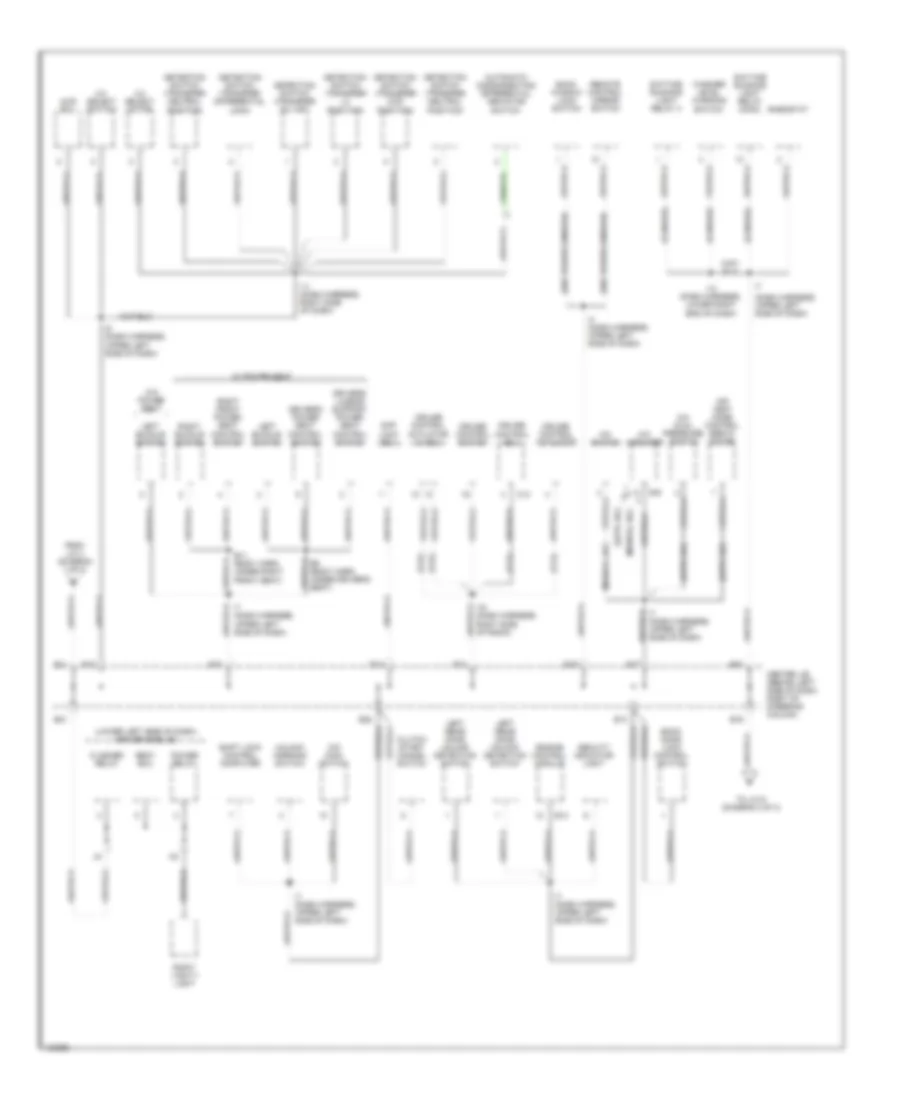
GROUND DISTRIBUTION
Ground Distribution Wiring Diagram (1 of 3) for Toyota 4Runner 1999
List of elements for Ground Distribution Wiring Diagram (1 of 3) for Toyota 4Runner 1999:
- (2.7l)
- (2wd, add)
- (4wd, add)
- (left side of engine compt, on inner fender panel) engine room r/b
- (w/ moon roof) personal light
- A17
- Abs ecu
- Abs relay
- Air bag sensor assembly
- B1 (body harness, inside left front door)
- B16
- B4 (body harness, center of windshield headed)
- Body ecu
- Brake fluid level warning switch
- C27
- Canada
- Cigarette lighter
- Clock
- Combination meter
- Combination switch
- Daytime
- E5 (eng compt harn, left front of engine compt)
- Efi relay
- Engine
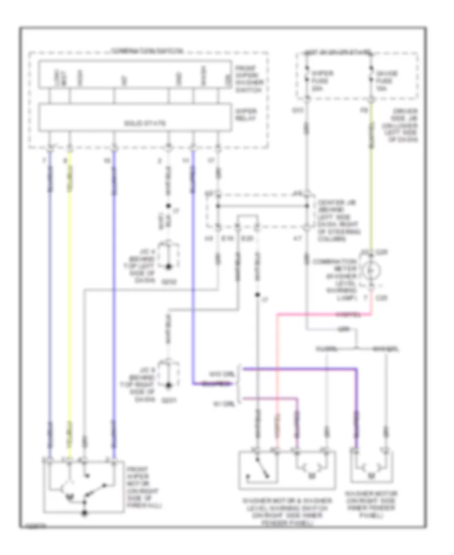
- Front wiper & washer switch
- Fuel pump
- G100 (front of left front fender)
- G119 (right front of engine)
- G202 (left side of dash)
- G203 (right kick panel)
- G405 (right rear side of luggage compt)
- Glove box light
- Heater relay
- Hood courtesy switch
- I3 (dash harness, behind fuse box)
- I5 (dash harness, upper left side of dash)
- I7 (dash harness, upper left side of dash)
- Ignition coil & igniter 1
- Ignition coil & igniter 2
- J/c 1 & 2 (in engine room r/b, left front of engine compt)
- J/c 12 & 13 (under left rear seat)
- J/c 4 (upper left end of dash)
- J12
- J13
- Left front door key lock & unlock switch
- Left front door lock control switch
- Left front door lock motor & door unlock detection switch
- Left front fog- light
- Left front parking light
- Left front power outlet
- Left front turn signal light
- Left mirror heater
- Moon roof control motor & limit switch
- Moon roof control relay & switch
- Power outlet relay
- Power window master switch
- Rear differential lock detection switch
- Rear differential lock motor
- Rear power outlet
- Rear window defogger switch
- Right front buckle switch
- Right front fog- light
- Right front parking light
- Right front turn signal light
- Running light resistor
- Starter relay
- To center j/b pin e11 (diagram 2 of 3)
- To data link connector 3 (diagram 3 of 3)
- To junction connector 9 (diagram 3 of 3)
- Unlock warning switch
- Vacuum solenoid valve
- W/o power seat
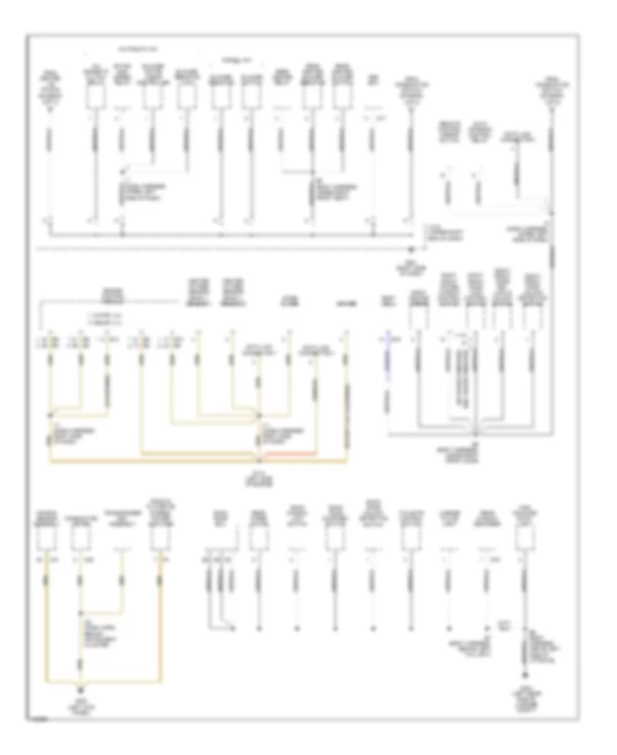
Ground Distribution Wiring Diagram (2 of 3) for Toyota 4Runner 1999
List of elements for Ground Distribution Wiring Diagram (2 of 3) for Toyota 4Runner 1999:
- (2.7l)
- (3.4l)
- (auto a/c)
- (canada)
- (dash harness, upper left side of dash)
- (lower left side of dash) driver side j/b
- (manual a/c)
- (w/o power window)
- 2-4 select motor
- 2-4 select switch
- 4wd ecu
- A/c amplifier
- A/c dual pressure switch
- A/c switch
- A30
- Air vent mode control servo motor
- Automatic disconnecting differential indicator switch
- B11 (body harn, under right front seat)
- B9 (body harn, under driver's seat)
- Back door lock control switch
- Back window lock switch
- Body ecu
- C14
- Center j/b (behind left side of dash, right of steering column)
- Clutch start cancel switch
- Cruise control actuator
- Cruise control actuator w/ ecu
- Cruise control ecu
- Cruise control switch
- Daytime running light relay (main)
- Daytime running light relay 4
- Detection switch (transfer 4wd position)
- Detection switch (transfer differential lock)
- Detection switch (transfer h2, h4f)
- Detection switch (transfer l4 position)
- Detection switch (transfer neutral position)
- Diff lock ecu
- Driver's lumbar support power seat control switch
- Driver's power seat control switch
- E11
- E12
- E13
- E14
- E15
- E16
- E17
- E18
- E19
- E20
- E21
- E22
- Engine control module
- Flasher relay
- From j/c 4 (diagram 1 of 3)
- I11 (dash harness, right side of dash)
- I13 (dash harness, lower right end of dash)
- I16 (dash harness, right side of radio)
- I4 (dash harness, upper left side of dash)
- I5 (dash harness, upper left side of dash)
- I7 (dash harness, upper left side of dash)
- Left buckle switch
- Left rear door unlock detection switch
- O/d main switch
- Power relay
- Remote control mirror switch
- Rheostat
- Right buckle switch
- Right front power seat control switch
- Right vanity light
- Secuity indicator light
- Shift lock control computer
- To j/c 9 (diagram 3 0f 3)
- Unlock warning switch
- W/ power seat
- W/0 power seat
- Washer level warning switch
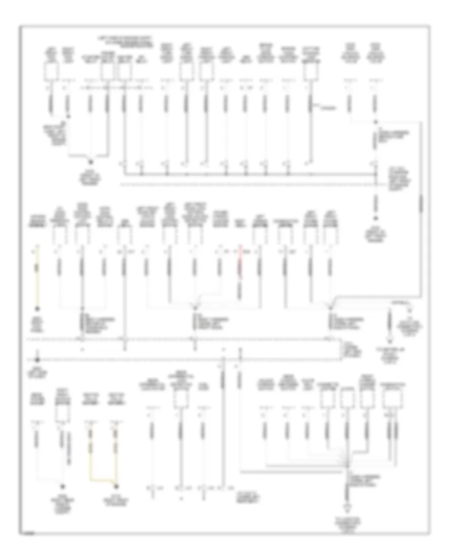
Ground Distribution Wiring Diagram (3 of 3) for Toyota 4Runner 1999
List of elements for Ground Distribution Wiring Diagram (3 of 3) for Toyota 4Runner 1999:
- (california)
- (except 3.4l california)
- (w/ power windows)
- (w/o power windows)
- 3rz-fe: 2.7l
- 5v2-fe: 3.4l
- A/c magnetic clutch relay
- A17
- Abs ecu
- Air bag sensor assembly
- Auto antenna control relay
- Automatic a/c
- B16
- B5 (body harness, inside right front door)
- B6 (body harness, above left side of liftgate)
- B7 (body harness, behind left taillight)
- B8 (body harness, under right front seat)
- Back door courtesy switch
- Back door ecu
- Back door unlock detection switch
- Back window limit switch
- Blower motor linear controller
- Blower resistor
- Blower resistor (low)
- Blower switch
- Body ecu
- C21
- C25
- Combination meter
- Data link connector 1
- Data link connector 3
- E10
- Engine control module
- Extra high speed relay
- From center j/b pin e16 (diagram 2 of 3)
- From combination switch (diagram 1 of 3)
- G112 (left side of engine)
- G200 (left kick panel)
- G201 (right side of dash)
- G404 (left rear side of luggage compt)
- Heated oxygen sensor (bank 1, sensor 1)
- Heated oxygen sensor (bank 1, sensor 2)
- High mounted stop- light
- I11 (dash harness, right side of dash)
- I22 (dash harn, behind instrument cluster)
- I5 (dash harness, upper left side of dash)
- I7 (dash harness, upper left side of dash)
- Igniter
- J/c 9 (upper right end of dash)
- License plate light
- Manual a/c
- Noise filter
- R18
- Radio & player or stereo power amplifier
- Rear heater blower resistor
- Rear heater blower switch
- Rear heater relay
- Rear window defogger
- Rear wiper motor
- Remote control mirror switch
- Right front door key lock & unlock switch
- Right front door lock control switch
- Right front door unlock detection switch
- Right front power window control switch
- Right heated mirror
- Tailgate control switch
- Transponder key assembly
HEADLIGHTS
Headlight Wiring Diagram, with DRL (1 of 2) for Toyota 4Runner 1999
List of elements for Headlight Wiring Diagram, with DRL (1 of 2) for Toyota 4Runner 1999:
- (dash harness, upper left side of dash) i5
- (dash harness, upper right side of dash) i19
- B17
- Body ecu (on driver side j/b)
- Brake indicator
- C27
- C29
- Center j/b (behind left side of dash, to right of steering column)
- Combination meter
- Combination switch
- Daytime running light relay (main) (behind left side of dash, right of steering column)
- Daytime running light relay 4 (behind right side of dash)
- Dimmer switch
- Diode (daytime running light 1) (behind right side of dash, on top)
- Diode (daytime running light 2) (behind right side of dash, on top)
- Dome fuse 15a
- Driver side j/b (on lower left side of dash)
- Drl fuse 7.5a
- Engine room r/b (on left side of engine compartment, on inner fender panel)
- Exterior lights system
- Flash
- Foglight switch
- G202
- Gauge fuse 10a
- Head
- Head relay
- High
- High beam indicator
- Hot at all times
- Hot in on or start
- Hry
- I7 (dash harn, upper center of dash)
- J/c 3 (behind left side of dash, on top)
- J/c 4 (behind left side of dash, on top)
- Left front door courtesy switch
- Light control switch
- Low
- Off
- Red
- Solid state
- Starting/ charging system
- Tail
Headlight Wiring Diagram, with DRL (2 of 2) for Toyota 4Runner 1999
List of elements for Headlight Wiring Diagram, with DRL (2 of 2) for Toyota 4Runner 1999:
- (engine harness, behind driver side j/b) i3
- (engine harness, left front fender) e5
- (front of left front fender) g100
- A j/c 1
- A j/c 2
- Brake fluid level warning switch (on brake fluid reservoir)
- Center j/b (behind left side of dash, to right of steering column)
- D10
- D11
- D12
- Daytime running light resistor (on left front of engine compartment)
- Dimmer relay
- E16
- E20
- Engine room r/b (on left side of engine compartment, on inner fender panel)
- Fog fuse 15a
- Fog relay (if equipped)
- G201
- Hot at all times
- If equipped
- J/c 9 (behind right side of dash)
- Junction connector (on left front inner fender panel, front of strut tower)
- Left front foglight
- Left headlight
- Left hi head fuse 10a
- Left lo head fuse 10a
- Parking brake switch (under center console)
- Pnk
- Right front foglight
- Right headlight
- Right hi head fuse 10a
- Right lo head fuse 10a
Headlight Wiring Diagram, without DRL for Toyota 4Runner 1999
List of elements for Headlight Wiring Diagram, without DRL for Toyota 4Runner 1999:
- (engine harness, left front fender) e5
- A13
- B12
- Combination meter
- Combination switch
- Dimmer switch
- Driver side j/b (on lower left side of dash)
- E17
- Engine room r/b (on left side of engine compartment, on inner fender panel)
- Exterior lights system
- Flash
- Fog fuse 15a
- Fog relay (if equipped)
- Fog- light switch
- G202
- Gauge fuse 10a
- Head
- Head relay
- High
- High beam indicator
- Hot at all times
- Hot in on or start
- I3 (engine harness, behind driver side j/b)
- If equipped
- J/c 3 (behind left side of dash, on top)
- J/c 4 (behind left side of dash, on top)
- Left front door courtesy switch
- Left front foglight
- Left head fuse 10a
- Left headlight
- Light control switch
- Low
- Off
- Pnk
- Red
- Right front foglight
- Right head fuse 10a
- Right headlight
- Solid state
- Tail
HORN
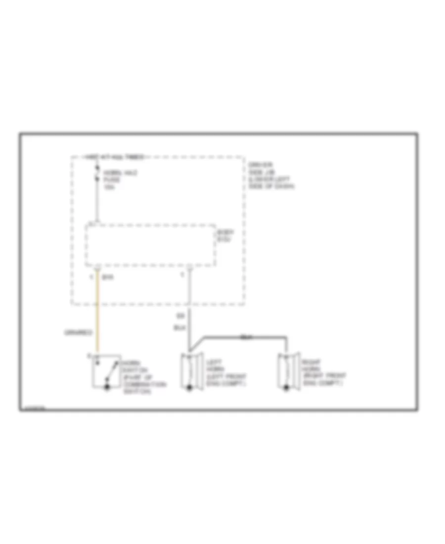
Horn Wiring Diagram for Toyota 4Runner 1999
List of elements for Horn Wiring Diagram for Toyota 4Runner 1999:
- B16
- Body ecu
- Driver side j/b (lower left side of dash)
- Horn switch (part of combination switch)
- Horn, haz fuse 15a
- Hot at all times
- Left horn (left front eng compt)
- Right horn (right front eng compt)
INSTRUMENT CLUSTER
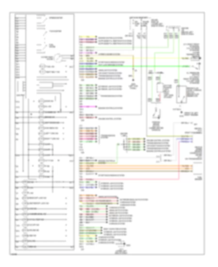
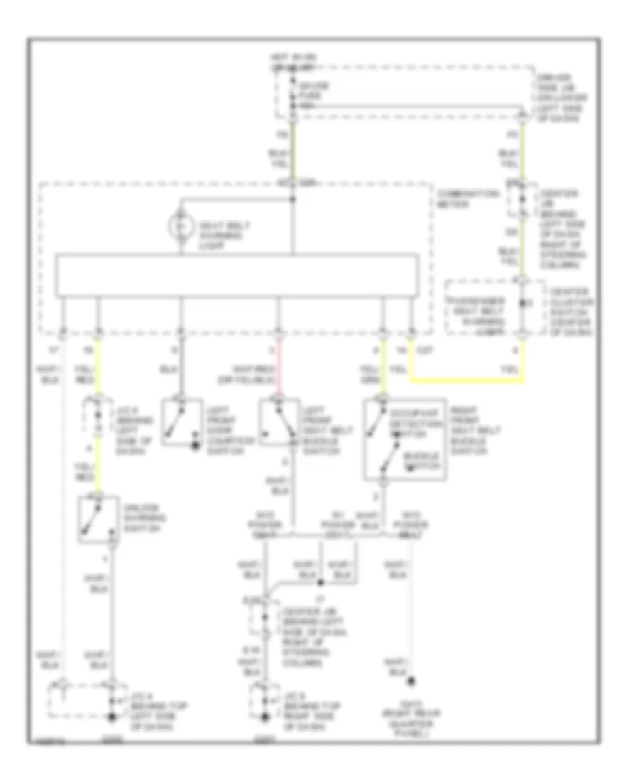
Instrument Cluster Wiring Diagram for Toyota 4Runner 1999
List of elements for Instrument Cluster Wiring Diagram for Toyota 4Runner 1999:
- (2.7l-right front of engine, 3.4l-left side of engine)
- (2.7l-right front of engine, 3.4l-top rear of engine)
- (front of left front fender)
- (w/ drl)
- (w/ power seat)
- (w/o drl)
- (w/o power seat)
- 2 ind
- 2.7l
- 3.4l
- 4wd ind
- A/t oil temp ind
- A/t p ind
- A10
- A11
- A12
- A13
- A14
- A15
- A16
- Abs ecu (3.4l) (right kick panel)
- Abs ind
- Air conditioning system
- Anti-lock brakes system
- B10
- B11
- B12
- B13
- Body computer system
- Brake fluid level warning switch (brake fluid reservoir)
- Brake ind
- C10
- C25
- C26
- C27
- C28
- C29
- Center diff lock ind
- Center j/b
- Center j/b (behind left side of dash)
- Charge ind
- Cruise control system
- Cruise ind
- D ind
- D10
- D11
- D12
- Daytime running light relay (main) (left side of dash)
- Door ind
- Driver side j/b (lower left side of dash)
- E10
- E11
- E12
- E13
- E14
- E15
- E16
- E17
- E18
- Ect power ind
- Engine controls system
- Exterior lights system
- Exterior/headlights system
- F11
- Fuel gauge
- Fuel ind
- Fuel sender
- G100
- G200 (left kick panel)
- G202
- Gauge fuse 10a
- Headlights system
- High beam ind
- Hot in on or start
- I22
- Ign fuse 10a
- Illum
- Interior lights system
- J/c 4 (upper left end of dash)
- L ind
- Left turn ind
- Mil ind
- N ind
- O/d off ind
- Odo/trip
- Oil ind
- Oil pressure switch
- P ind
- Parking brake switch (under center console)
- R ind
- Rear diff lock ind
- Red
- Right turn ind
- Seat belt ind
- Sp1
- Speedometer
- Srs ind
- Starting/charging system
- Tachometer
- Transmissions system
- Vehicle speed sensor (combination meter) (2.7l) (on transmission)
- W/ drl
- W/o drl
- Warning system
- Washer level ind
- Water temp gauge
- Water temperature sensor
- Wiper/washer system
INTERIOR LIGHTS
Courtesy Lamps Wiring Diagram for Toyota 4Runner 1999
List of elements for Courtesy Lamps Wiring Diagram for Toyota 4Runner 1999:
- (1999, 2000) (2001)
- B3 b2 (body harn, at left "a" pillar)
- Back door courtesy switch (on left side of back door)
- Back door ecu (left side of back door)
- Body ecu
- Body ecu (on driver side j/b)
- C10
- C27
- C28
- Center j/b (behind left side of dash, right of steering column)
- Combination meter
- Dome fuse 15a
- Door
- Driver side j/b (on lower left side of dash)
- E16
- E21
- Engine room r/b (left side of engine compt, on inner fender panel)
- Front interior light
- G201
- G202
- G404 (left rear side of luggage compartment)
- Hot at all times
- I12 i5 (i12: dash harn, right side of dash) (i5: dash harn, left end of dash)
- I12 i9 (i12: dash harn, right side of dash) (i9: dash harn, left side of dash)
- I22 i9 (dash harn, left side of dash)
- Ignition key cylinder light
- J/c 4 (upper left end of dash)
- J/c 9 (upper right end of dash)
- Left front door courtesy switch
- Left rear door courtesy switch
- Off
- Open door warning
- Personal light (if equipped)
- Rear interior light
- Right front door courtesy switch
- Right rear door courtesy switch
- Right vanity light (if equipped)
- W/ moonroof
- W/o moonroof
Instrument Illumination Wiring Diagram for Toyota 4Runner 1999
List of elements for Instrument Illumination Wiring Diagram for Toyota 4Runner 1999:
- (1999, 2000)
- (1999, 2000) (2001)
- (2001) (w/ manual a/c) a/c amplifier
- (dash harn, center of dash) i23 i19
- A/c amplifier (w/ auto a/c)
- A/c switch (w/ manual a/c) (1999, 2000)
- A/t shift lever illumination (a/t)
- Ashtray illumination
- Back door lock control switch (w/o door locks) (1999, 2000)
- Back window lock switch (if equipped)
- Blower switch (1999, 2000)
- C27
- C28
- Center cluster switch
- Center j/b (behind left side of dash, right of steering column)
- Cigarette lighter illumination
- Combination meter
- D13
- D14
- D15
- D17
- D18
- D20
- Driver's side j/b (lower left side of dash)
- E16
- E20
- Engine room r/b (left side of engine compt, on inner fender panel)
- F10
- F11
- F12
- F14
- F16
- F17
- F18
- F19
- F20
- G201
- G202
- Glove box light
- Hazard switch
- Head
- Hot at all times
- I9 (dash harn, center of dash)
- J/c 1, j/c 2 (left inner fender panel, front of strut tower)
- J/c 4 (upper left end of dash)
- J/c 5 (behind left side of dash)
- J/c 9 (upper right end of dash)
- Light control switch (part of combination switch)
- Off
- Radio & player or stereo power amplifier
- Rheostat
- Tail
- Tail fuse 10a
- Tail relay
POWER ANTENNA
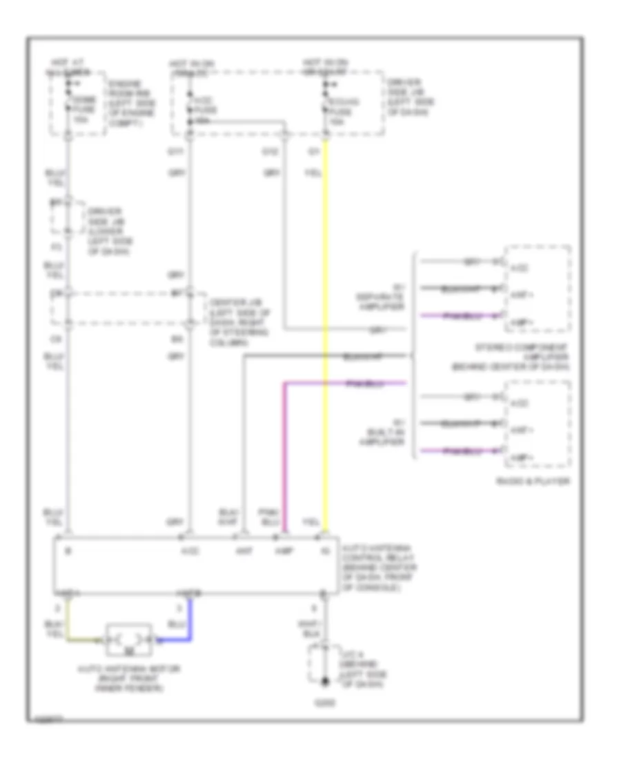
Power Antenna Wiring Diagram for Toyota 4Runner 1999
List of elements for Power Antenna Wiring Diagram for Toyota 4Runner 1999:
- Acc
- Acc fuse 15a
- Amp
- Amp+
- Ant
- Ant+
- Anta
- Antb
- Auto antenna control relay (behind center of dash, front of console)
- Auto antenna motor (right front inner fender)
- Center j/b (left side of dash, right of steering column)
- Dome fuse 15a
- Driver side j/b (left side of dash)
- Driver side j/b (lower left side of dash)
- Ecu-ig fuse 10a
- Engine room r/b (left side of engine compt)
- G11
- G12
- G202
- Hot at all times
- Hot in on or acc
- Hot in on or start
- J/c 4 (behind left side of dash)
- Radio & player
- Stereo component amplifier (behind center of dash)
- W/ built-in amplifier
- W/ separate amplifier
POWER DISTRIBUTION
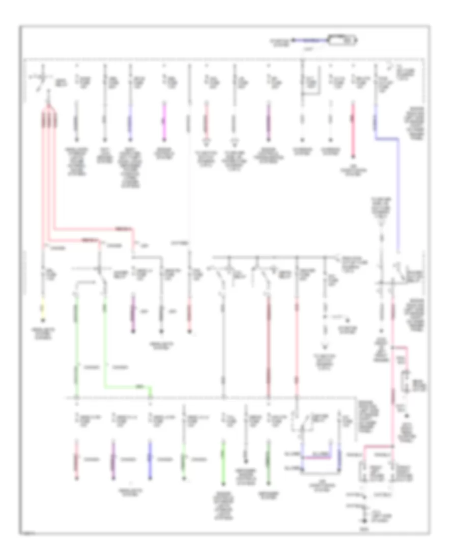
Power Distribution Wiring Diagram (1 of 2) for Toyota 4Runner 1999
List of elements for Power Distribution Wiring Diagram (1 of 2) for Toyota 4Runner 1999:
- A/c fuse 10a
- Abs fuse 60a
- Air conditioning system
- Alt fuse 120a
- Alt-s fuse 7.5a
- Am1 fuse 40a
- Am2 fuse 30a
- Anti- lock brakes system
- Battery
- Body computer, anti-theft, door locks, defogger, power windows, wiper/ washer systems
- Canada
- Charging system
- Defog fuse 15a
- Defog relay
- Defogger system
- Defogger, engine controls systems
- Dimmer relay
- Dome fuse 15a
- Drl fuse 7.5a
- Efi fuse 20a
- Engine
- Engine controls system
- Engine controls, exterior lights, interior lights systems
- Engine controls, transmissions systems
- Engine room r/b (left side of engine compt, on inner fender panel)
- Fog fuse 15a
- From pwr outlet fuse (diagram 1 of 2)
- Front left power outlet
- Front right power outlet
- G100 (front of left front fender)
- G202
- G413 (right rear quarter panel)
- Head hi lh fuse 10a
- Head hi rh fuse 10a
- Head lh fuse 10a
- Head lo lh fuse 10a
- Head lo rh fuse 10a
- Head relay
- Head rh fuse 10a
- Headlamps, interior lights, power antenna, sound systems
- Headlights system
- Headlights system (canada)
- Heater fuse 50a
- Heater relay
- J/b fuse 50a
- J/c 4 (left side of dash)
- Mir htr fuse 10a
- Mpx-b fuse 15a
- Obd fuse 7.5a
- Pnk
- Power outlet relay
- Pwr outlet fuse 15a
- Rear power outlet
- Red
- Room r/b (left side of engine compt, on inner fender panel)
- Rr htr fuse 10a
- Starting system
- Tail fuse 10a
- Tail relay
- To am1 fuse (diagram 1 of 2)
- To driver side j/b, acc fuse (diagram 2 of 2)
- To driver side j/b, power fuse (diagram 2 of 2)
- To ignition switch (diagram 2 of 2)
- Usa
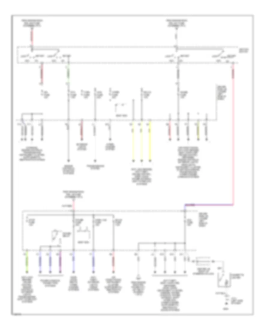
Power Distribution Wiring Diagram (2 of 2) for Toyota 4Runner 1999
List of elements for Power Distribution Wiring Diagram (2 of 2) for Toyota 4Runner 1999:
- 4wd fuse 20a
- Acc
- Acc fuse 15a
- Air conditioning, anti-lock brakes, body computer, cruise control, defogger, engine controls, exterior lights, headlights, instrument cluster, starting/charging, transmissions, wiper/washer, warning systems
- Anti- theft, exterior lights, horns systems
- Anti-lock brakes, anti-theft, cruise control, door locks, power antenna, shift interlock systems
- Anti-lock brakes, cruise control, engine controls, exterior lights, transmissions, shift interlock systems
- Body ecm
- Center j/b (right of steering column)
- Cigarette lighter
- Door locks, seats, wiper/ washer systems
- Driver side j/b (lower left side of dash)
- Ecu-b fuse 7.5a
- Ecu-ig fuse 10a
- Engine controls, starting systems
- Exterior lights system
- F10
- F11
- From engine room r/b, am1 fuse (diagram 1 of 2)
- From engine room r/b, am2 fuse (diagram 1 of 2)
- From engine room r/b, j/b fuse (diagram 1 of 2)
- From engine room r/b, power out- let relay (diagram 1 of 2)
- G10
- G11
- G12
- G13
- G202
- Gauge fuse 10a
- Horn, haz fuse 15a
- Ign fuse 10a
- Ignition switch
- J/c 4 (left side of dash)
- Lock
- Power fuse 30a
- Power relay
- Power windows, power tops systems
- Sta fuse 7.5a
- Start
- Stop fuse 10a
- Transmissions system
- Turn fuse 10a
- Wiper fuse 20a
- Wiper/ washer system
POWER DOOR LOCKS
Power Door Lock Wiring Diagram, with Keyless Entry for Toyota 4Runner 1999
List of elements for Power Door Lock Wiring Diagram, with Keyless Entry for Toyota 4Runner 1999:
- (1999)
- (2000)
- (behind left side of dash) j/c 4
- (behind left side of dash, to right of steering column) center j/b
- (body harn, base of left "b" pillar)
- (dash harn, right side of dash) i12
- (left rear quarter panel) g414
- (on left side of back door) back door ecu
- (w/ anti- theft)
- 2.7l
- 3.4l
- Acc fuse 15a
- B10
- B16
- B17
- Back door courtesy switch
- Back door lock motor & unlock detection switch
- Back window limit switch
- Back window motor
- Body ecu
- Center j/b (behind left side of dash, to right of steering column)
- Door courtesy switches
- Driver side j/b (on lower left side of dash)
- E13
- E16
- E21
- Ecu-ig fuse 10a
- Engine room r/b (on left side of engine compt, on inner fender panel)
- Exterior lights system
- G11
- G201
- G202
- G404 (left rear side of luggage compt)
- H10
- Hot at all times
- Hot in run or acc
- Hot in run or start
- I1 (dash harn, at left kick panel)
- I12
- I7 (dash harn, center of dash)
- J/c 10, j/c 11 (at right kick panel)
- J/c 4 (behind left side of dash)
- J/c 6 (behind left side of dash)
- J/c 9 (behind right side of dash)
- Keyless buzzer (right rear of engine compt)
- Left front
- Left front door key lock & lock unlock switch
- Left front door lock motor & unlock detection switch
- Left front lock control switch (w/ power window: part of window lock master switch)
- Left rear
- Left rear door lock motor & unlock detection switch
- Lock
- Mpx-b fuse 15a
- Power fuse 30a
- Red
- Right front
- Right front door key lock & unlk unlock switch
- Right front door lock motor & unlock detection switch
- Right front lock control unlk switch
- Right rear
- Right rear door lock motor & unlock detection switch
- Unlk
- Unlock warning switch
- W/ power window
- W/o power window
Power Door Lock Wiring Diagram, without Keyless Entry for Toyota 4Runner 1999
List of elements for Power Door Lock Wiring Diagram, without Keyless Entry for Toyota 4Runner 1999:
- (dash harn, center of dash) i7
- (dash harn, right side of dash) i12
- 2.7l
- 3.4l
- B16
- Back door lock motor
- Body ecu
- Center j/b (behind left side of dash, to right of steering column)
- Driver side j/b (on lower left side of dash)
- E16
- E21
- Ecu-ig fuse 10a
- Engine room r/b (on left side of engine compt, on inner fender panel)
- G201
- G202
- H10
- Hot at all times
- Hot in run or start
- I1 (dash harn, at left kick panel)
- I12
- J/c 10, j/c 11 (at right kick panel)
- J/c 4 (behind left side of dash)
- J/c 6 (behind left side of dash)
- J/c 9 (behind right side of dash)
- Left front door courtesy switch
- Left front door key lock & lock unlock switch
- Left front door lock motor & unlock detection switch
- Left front lock control lock switch
- Left rear door lock motor
- Lock
- Mpx-b fuse 15a
- Power fuse 30a
- Red
- Right front door courtesy switch
- Right front door key lock & unlk unlock switch
- Right front door lock motor & unlock detection switch
- Right front lock control unlk switch
- Right rear door lock motor
- Unlk
- Unlock warning switch
- W/ power window
- W/o power window
POWER MIRRORS
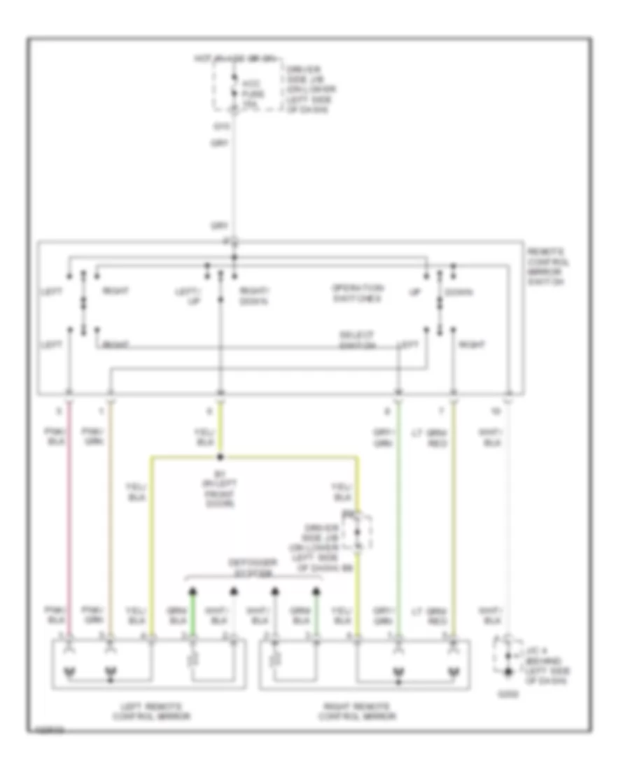
Power Mirror Wiring Diagram, with Power Windows for Toyota 4Runner 1999
List of elements for Power Mirror Wiring Diagram, with Power Windows for Toyota 4Runner 1999:
- Acc fuse 15a
- B1 (in left front door)
- Defogger system
- Down
- Driver side j/b (on lower left side of dash)
- G10
- G202
- Hot in acc or on
- J/c 4 (behind left side of dash)
- Left
- Left remote control mirror
- Left/ up
- Operation switches
- Remote control mirror switch
- Right
- Right remote control mirror
- Right/ down
- Select switch
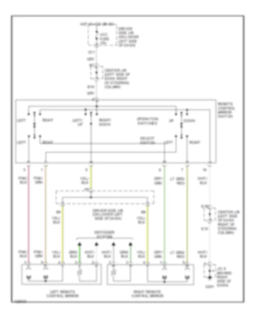
Power Mirror Wiring Diagram, without Power Windows for Toyota 4Runner 1999
List of elements for Power Mirror Wiring Diagram, without Power Windows for Toyota 4Runner 1999:
- Acc fuse 15a
- B10
- Center j/b (left side of dash, right of steering column)
- Defogger system
- Down
- Driver side j/b (on lower left side of dash)
- E16
- E19
- G11
- G201
- Hot in acc or on
- J/c 9 (behind right side of dash)
- Left
- Left remote control mirror
- Left/ up
- Operation switches
- Remote control mirror switch
- Right
- Right remote control mirror
- Right/ down
- Select switch
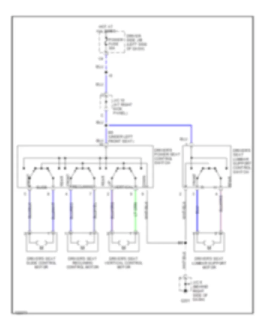
POWER SEATS
Driver Power Seat Wiring Diagram for Toyota 4Runner 1999
List of elements for Driver Power Seat Wiring Diagram for Toyota 4Runner 1999:
- B9 (under left front seat)
- Down
- Driver side j/b (left side of dash)
- Driver's power seat control switch
- Driver's seat lumbar support control switch
- Driver's seat lumbar support motor
- Driver's seat reclining control motor
- Driver's seat slide control motor
- Driver's seat vertical control motor
- Front
- G201
- Hot at all times
- J/c 10 (at right kick panel)
- J/c 9 (behind right side of dash)
- Power fuse 30a
- Rear
- Reclining
- Slide
- Vertical
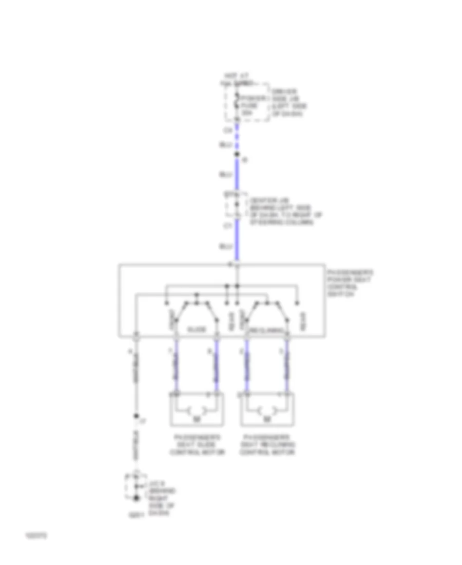
Passenger Power Seat Wiring Diagram for Toyota 4Runner 1999
List of elements for Passenger Power Seat Wiring Diagram for Toyota 4Runner 1999:
- Center j/b (behind left side of dash, to right of steering column)
- Driver side j/b (left side of dash)
- Front
- G201
- Hot at all times
- J/c 9 (behind right side of dash)
- Passenger's power seat control switch
- Passenger's seat reclining control motor
- Passenger's seat slide control motor
- Power fuse 30a
- Rear
- Reclining
- Slide
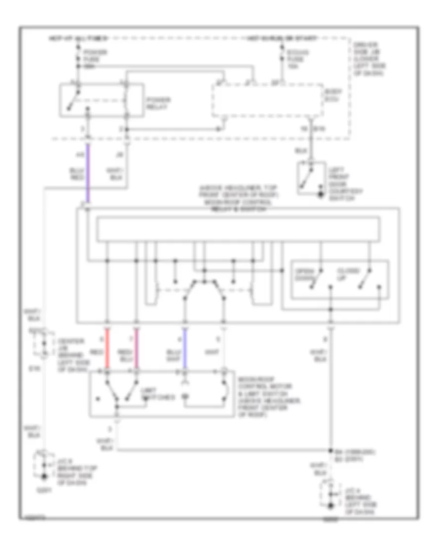
POWER TOP/SUNROOF
Power Top/Sunroof Wiring Diagrams for Toyota 4Runner 1999
List of elements for Power Top/Sunroof Wiring Diagrams for Toyota 4Runner 1999:
- (1999-200) (2001)
- (above headliner, top front center of roof) moon roof control relay & switch
- B16
- B4 b3
- Body ecu
- Center j/b (behind left side of dash)
- Close/ up
- Driver side j/b (lower left side of dash)
- E16
- E21
- Ecu-ig fuse 10a
- G201
- G202
- Hot at all times
- Hot in run or start
- J/c 4 (behind left side of dash)
- J/c 9 (behind top right side of dash)
- Left front door courtesy switch
- Limit switches
- Moon roof control motor & limit switch (above headliner, front center of roof)
- Open/ down
- Power relay
- Power fuse 30a
- Red
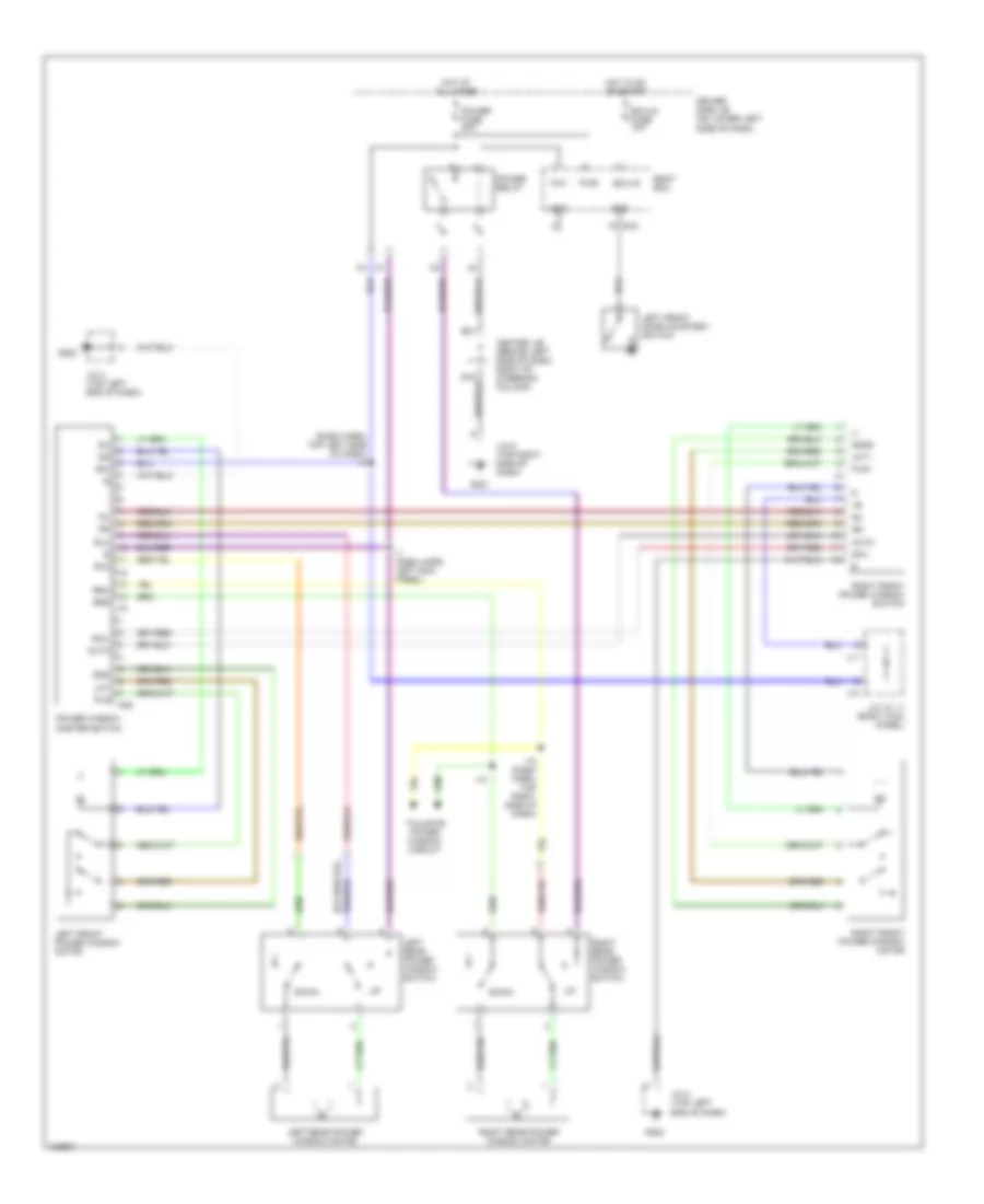
POWER WINDOWS
Power Windows Wiring Diagram for Toyota 4Runner 1999
List of elements for Power Windows Wiring Diagram for Toyota 4Runner 1999:
- (dash harn, top left side of dash) i5
- Auto
- B16
- Body ecu
- Center j/b (behind left side of dash, right of steering column)
- Down
- Driver side j/b (on lower left side of dash)
- E21
- Ecu-ig
- Ecu-ig fuse 10a
- G201
- G202
- Gnd
- Hot at all times
- Hot in on or start
- I1 (dash harn, left kick panel)
- I10
- I10 (dash harn, top right side of dash)
- J/c 10, 11 (right kick panel)
- J/c 4 (top left end of dash)
- J/c 9 (top right side of dash)
- J10
- J11
- Left front door courtesy switch
- Left front power window motor
- Left rear power window motor
- Left rear power window switch
- Lmt
- Lmt+
- P/w
- P26
- Pls
- Pls+
- Power fuse 30a
- Power relay
- Power window master switch
- Pwr
- Right front power window motor
- Right front power window switch
- Right rear power window motor
- Right rear power window switch
- Rld
- Rlu
- Rrd
- Rru
- Sgnd
- Swl
- Tailgate power window circuit
Tailgate Power Window Wiring Diagram for Toyota 4Runner 1999
List of elements for Tailgate Power Window Wiring Diagram for Toyota 4Runner 1999:
- Acc
- Acc fuse 15a
- B16
- Back door ecu (on left side of back door)
- Back window control switch
- Back window limit switch
- Back window lock switch
- Back window motor (in center of back door)
- Body ecu
- Center j/b (behind left side of dash, to right of steering column)
- Cls
- Clsm
- Diode (back window) (top right side of dash)
- Down
- Driver side j/b (on lower left side of dash)
- E16
- E19
- E21
- Ecu-b
- Ecu-ig
- Ecu-ig fuse 10a
- Engine room r/b (left side of engine compartment)
- Front & rear window circuit
- G11
- G201
- G404 (left rear side of luggage compt)
- Gnd
- Hot at all times
- Hot in acc
- Hot in on or start
- J/c 5 (behind left side of dash)
- J/c 9 (behind top right side of dash)
- Lmtw
- Mpx-b fuse 15a
- Mpx1
- Mx1
- Opn
- Opnm
- Power
- Power fuse 30a
- Pwr
- Red
- Tailgate control switch
- W/ power window
- W/o power window
- Wiper fuse 20a
RADIO
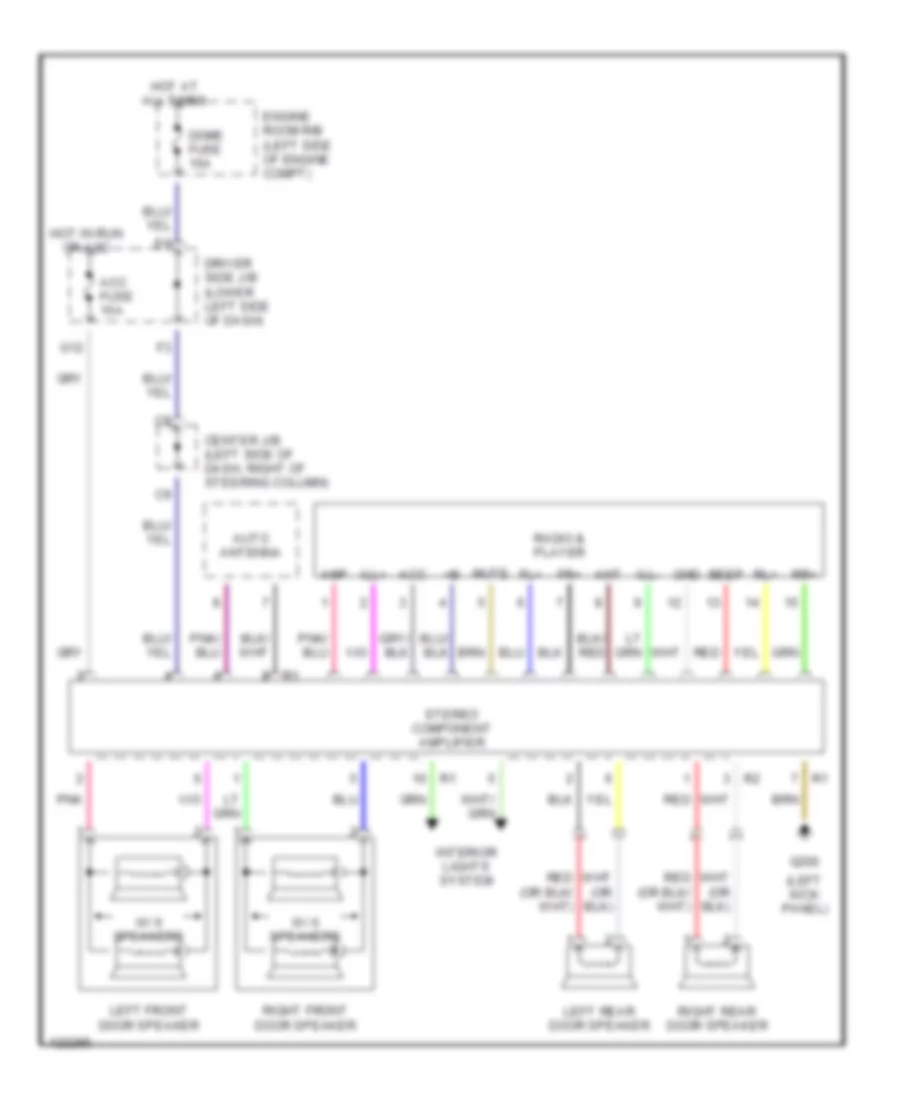
Radio Wiring Diagrams, with Amplifier for Toyota 4Runner 1999
List of elements for Radio Wiring Diagrams, with Amplifier for Toyota 4Runner 1999:
- (left kick panel)
- Acc
- Acc fuse 15a
- Amp
- Ant
- Auto antenna
- Beep
- Center j/b (left side of dash, right of steering column)
- Dome fuse 15a
- Driver side j/b (lower left side of dash)
- Engine room r/b (left side of engine compt)
- Fl+
- Fr+
- G12
- G200
- Gnd
- Hot at all times
- Hot in run or acc
- Ill+
- Ill-
- Interior lights system
- Left front door speaker
- Left rear door speaker
- Mute
- Pnk
- Radio & player
- Red
- Right front door speaker
- Right rear door speaker
- Rl+
- Rr+
- Stereo component amplifier
- W/ 6 speakers
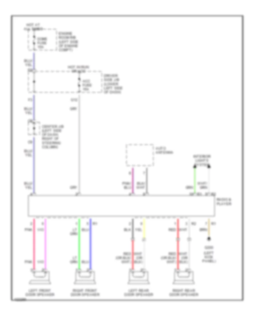
Radio Wiring Diagrams, without Amplifier for Toyota 4Runner 1999
List of elements for Radio Wiring Diagrams, without Amplifier for Toyota 4Runner 1999:
- (left kick panel)
- Acc fuse 15a
- Auto antenna
- Center j/b (left side of dash, right of steering column)
- Dome fuse 15a
- Driver side j/b (lower left side of dash)
- Engine room r/b (left side of engine compt)
- G12
- G200
- Hot at all times
- Hot in run or acc
- Interior lights system
- Left front door speaker
- Left rear door speaker
- Pnk
- Radio & player
- Red
- Right front door speaker
- Right rear door speaker
SHIFT INTERLOCKS
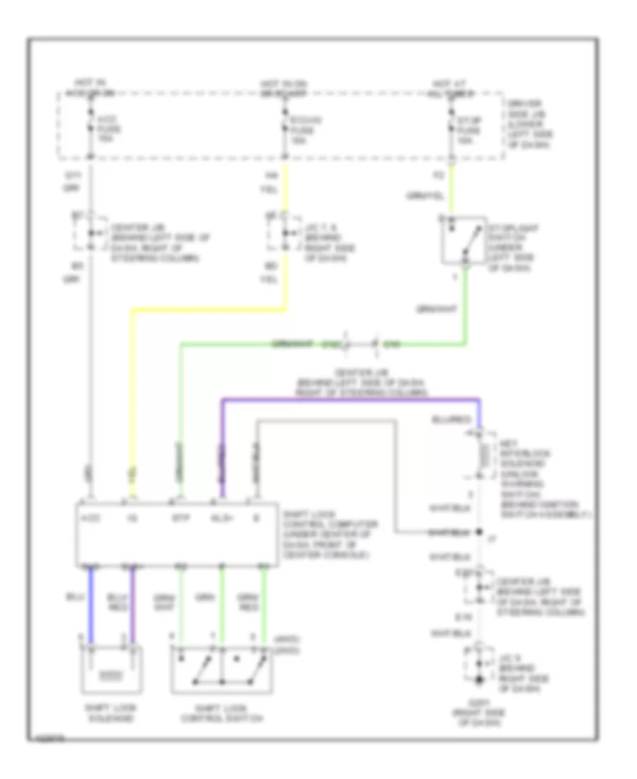
Shift Interlock Wiring Diagram for Toyota 4Runner 1999
List of elements for Shift Interlock Wiring Diagram for Toyota 4Runner 1999:
- (2wd)
- (4wd)
- Acc
- Acc fuse 15a
- C12
- C15
- Center j/b (behind left side of dash, right of steering column)
- Driver side j/b (lower left side of dash)
- E16
- E22
- Ecu-ig fuse 10a
- G11
- G201 (right side of dash)
- Hot at all times
- Hot in acc or on
- Hot in on or start
- J/c 7, 8 (behind right side of dash)
- J/c 9 (behind right side of dash)
- Key interlock solenoid (unlock warning switch) (behind ignition switch assembly)
- Kls+
- Shift lock control computer (under center of dash, front of center console)
- Shift lock control switch
- Shift lock solenoid
- Sls+
- Sls-
- Stop fuse 10a
- Stoplight switch (under left side of dash)
- Stp
STARTING/CHARGING
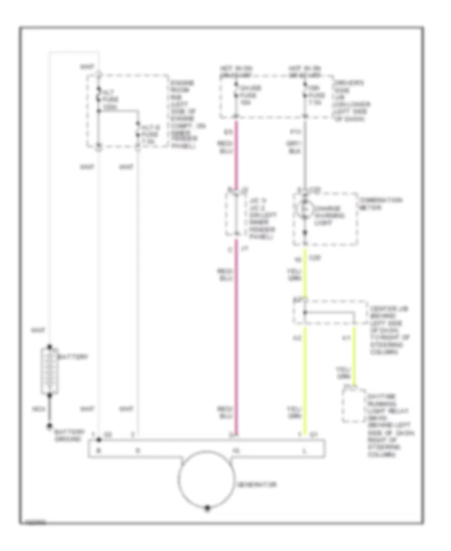
Charging Wiring Diagram for Toyota 4Runner 1999
List of elements for Charging Wiring Diagram for Toyota 4Runner 1999:
- Alt fuse 120a
- Alt-s fuse 7.5a
- Battery
- Battery ground
- C25
- Center j/b (behind left side of dash, to right of steering column)
- Charge warning light
- Combination meter
- Daytime running light relay (main) (behind left side of dash, right of steering column)
- Driver's side j/b (on lower left side of dash)
- Engine room r/b (left side of engine compt, on inner fender panel)
- F11
- Gauge fuse 10a
- Generator
- Hot in on or start
- Ign fuse 7.5a
- J/c 1/ j/c 2 (on left inner fender panel)
- Nca
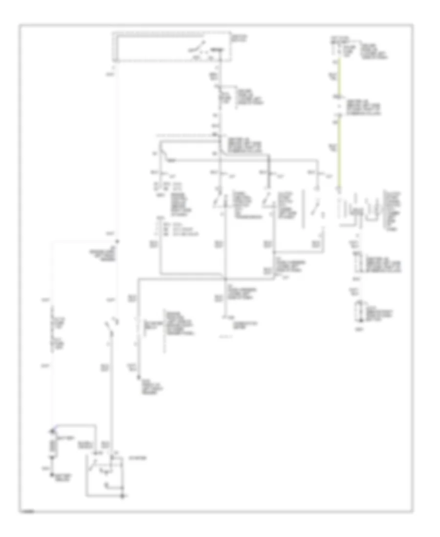
Starting Wiring Diagram for Toyota 4Runner 1999
List of elements for Starting Wiring Diagram for Toyota 4Runner 1999:
- (2.7l calif)
- (2.7l ex calif)
- (2.7l)
- (3.4l)
- A/t
- Acc
- Alt fuse 120a
- Alt-s fuse 7.5a
- Battery
- Battery ground
- C28
- Center j/b (behind left side of dash, right of steering column)
- Clutch start cancel switch (m/t) (under left side of dash)
- Clutch start switch (m/t) (under left side of dash)
- Combination meter
- Driver side j/b (lower left side of dash)
- E12
- E14
- E16
- E22
- E3 (engine harn, left front fender)
- Engine control module (behind right side of dash)
- Engine room r/b (left side of engine compt, on inner fender panel)
- G100 (front of left front fender)
- G201
- Gauge fuse 10a
- Hot in on or start
- I21 (dash harness, lower left side of dash)
- Ignition switch
- J/c 9 (behind right side of dash, on top)
- M/t
- Nca
- Nsw
- Off
- P/ n
- Park/ neutral position switch (a/t) (on transmission)
- Solid state
- Sta
- Sta fuse 7.5a
- Start
- Starter
- Starter relay
SUPPLEMENTAL RESTRAINTS
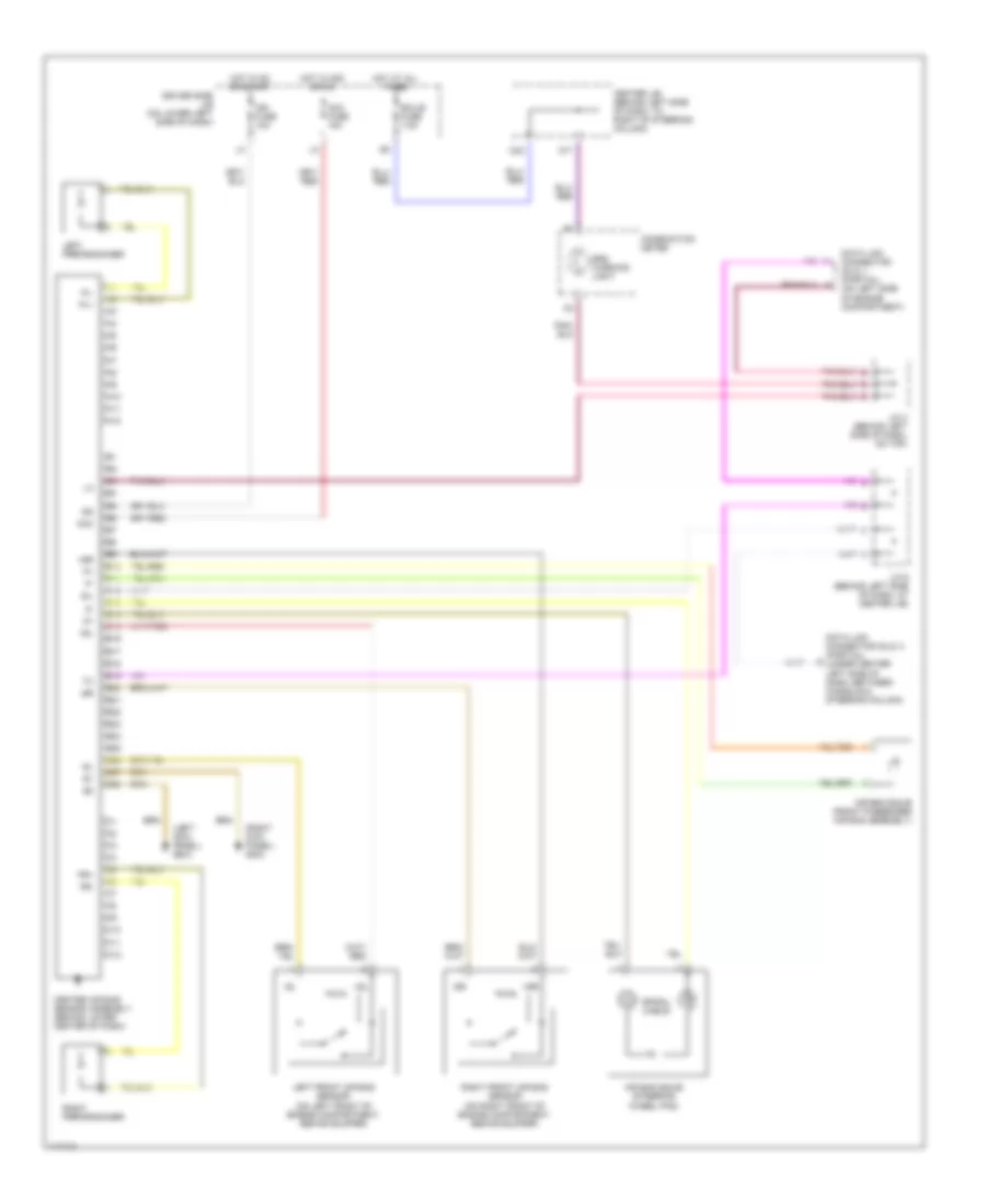
Supplemental Restraint Wiring Diagram for Toyota 4Runner 1999
List of elements for Supplemental Restraint Wiring Diagram for Toyota 4Runner 1999:
- (left kick panel) g200
- (right kick panel) g203
- +sl
- +sr
- -sl
- -sr
- A10
- A11
- A12
- Acc
- Acc fuse 15a
- Air bag squib (front passenger air bag assembly)
- Air bag squib (steering wheel pad)
- B10
- B11
- B12
- B13
- B14
- B15
- B16
- B17
- B18
- B19
- B20
- B21
- B22
- B23
- B24
- B25
- B26
- B27
- B28
- C10
- C11
- C12
- C17
- C22
- Center air bag sensor assembly (behind lower center of dash)
- Center j/b (behind left side of dash, to right of steering column)
- Combination meter
- Data link connector (dlc) 1 (partial) (on left side of engine compartment)
- Data link connector (dlc) 3 (partial) (under center left side of dash, between console & steering column)
- Driver side j/b (on lower left side of dash)
- Ecu-b fuse 7.5a
- Hot at all times
- Hot in acc or on
- Hot in on or start
- Ig2
- Ign fuse 10a
- J/c 3 (behind left side of dash, on top)
- J/c 6 (behind left side of dash, at center j/b)
- Left front air bag sensor (on left front of engine compartment, behind bumper)
- Left pretensioner
- Pl+
- Pl-
- Pr+
- Pr-
- Right front air bag sensor (on right front of engine compartment, behind bumper)
- Right pretensioner
- Sil
- Spiral cable
- Srs warning light
TRANSMISSION
2.7L
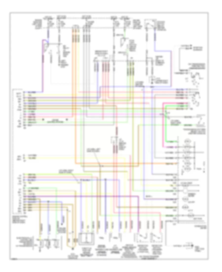
2.7L, A/T Wiring Diagram for Toyota 4Runner 1999
List of elements for 2.7L, A/T Wiring Diagram for Toyota 4Runner 1999:
- (behind right side of dash) j/c j7,j8
- (i/p harn, center of dash)
- (i/p harn, left side of dash)
- (i/p harn, right side of dash)
- (left front fender) g100
- (on trans/transfer case assembly)
- (on transmission) park/neutral position switch
- A/t fluid temperature sensor (in trans)
- A/t oil temp
- A/t p
- Batt
- C15
- C25
- C26
- C27
- C28
- C29
- Center j/b (right of steering column)
- Combination meter
- Cruise control system
- Detection switch (transfer l4 position)
- Detection switch (transfer neutral position)
- Driver side j/b (lower left side of dash)
- E10
- E16
- E18
- E22
- Ect pwr
- Efi
- Efi fuse 20a
- Electronically controlled transmission solenoid (in transmission)
- Engine control module (behind right side of dash)
- Engine coolant
- Engine room r/b (left side of eng compt)
- Eo1
- Eo2
- Eo3
- F10
- G131 (on intake manifold)
- G200 (left kick panel)
- G201
- Guage fuse 10a
- Hot at all times
- Hot in on or start
- Hot in start
- I11
- I19
- Ign fuse 10a
- J/c 9 (upper right end of dash)
- J/c j7,j8 (behind right side of dash)
- Nsw
- O/d main switch (below center console)
- O/d off
- Od1
- Od2
- Oil
- Oil-w
- Pwr
- Relay (in engine room r/b)
- Rl nl
- Sol
- Sp1
- Sp2+
- Sp2-
- Speedo- meter
- Sta fuse 7.5a
- Starting/ charging
- Stop fuse 10a
- Stop light switch (above brake pedal)
- Temperature sensor (top front of engine)
- Tfn
- Throttle position sensor (on throttle body assy)
- Thw
- Transmission pattern select switch (center console)
- Vehicle speed sensor (electro- nically controlled transmission) (in transmission)
- Vta
4WD Wiring Diagram, with 2-4 Select Switch for Toyota 4Runner 1999
List of elements for 4WD Wiring Diagram, with 2-4 Select Switch for Toyota 4Runner 1999:
- (behind left side of dash)
- (left kick panel) differential lock ecu
- 2-4
- 2-4 select motor (on transfer case)
- 2-4 select switch (on shift lever)
- 4wd
- 4wd ecu (left kick panel)
- 4wd fuse 20a
- 4wd ind
- A/t indicator light switch (part of park/neutral position switch)
- A/t p ind
- Abs ecu (right kick panel)
- Add
- Add indicator switch (center middle of engine compt)
- C/c
- C25
- C28
- C29
- Center diff lock
- Center j/b (behind left side of dash)
- Combination meter
- Cruise control actuator w/ecu (right side of engine compt)
- Detection switch (h2 & h4f) (transfer case)
- Detection switch (l4 position) (transfer case)
- Detection switch (n position) (transfer case)
- Detection switch (shift diff lock) (transfer case)
- Detection switch (transfer diff lock) (transfer case)
- Driver side j/b (lower left side of dash)
- E12
- E13
- E16
- Engine control module (behind right side of dash)
- Ex1
- Ex13
- G100
- G201
- Gauge fuse 10a
- Gnd
- Hot in on or start
- I11
- I12 (dash harn, right side of dash)
- I20 (dash harn, right side of dash)
- Ind1
- Ind2
- J/c 1, j/c 2 (left inner fender panel)
- J/c 3
- J/c 5 (behind left side of dash)
- J/c 7, j/c 8 (behind right side of dash)
- J/c 9 (behind right side of dash)
- Pnk
- Spd
- Speed- ometer
- Tfn
- Tl1
- Tl2
- Tl3
- Tm1
- Tm2
- Vsv (2wd, add) (left side of engine compt)
- Vsv (4wd, add) (left side of engine compt)
4WD Wiring Diagram, without 2-4 Select Switch for Toyota 4Runner 1999
List of elements for 4WD Wiring Diagram, without 2-4 Select Switch for Toyota 4Runner 1999:
- (behind left side of dash)
- (dash harn, right side of dash) i11
- (dash harn, right side of dash) i12
- (transfer case)
- 2.7l
- 2.7l except california
- 3.4l
- 3.4l, 2.7l california
- 4wd
- 4wd fuse 20a
- 4wd ind
- A/t indicator light switch (part of park/neutral position switch)
- A/t parking ind
- Abs ecu (right kick panel)
- Add control relay (behind right side of dash)
- Add indicator switch (middle of engine compt)
- C25
- C26
- C29
- Center j/b (behind left side of dash)
- Combination meter
- Dectection switch (transfer 4wd pos) (transfer case)
- Dectection switch (transfer l4 pos) (transfer case)
- Detection switch (transfer neutral position)
- Differential lock ecu (left kick panel)
- Driver side j/b (lower left side of dash)
- E13
- E16
- Engine control module (behind right side of dash)
- Ex1
- Ex13
- G100 (left front inner fender panel)
- G201
- Gauge fuse 10a
- Hot in on or start
- I11
- J/c 1, j/c 2 (left inner fender panel)
- J/c 3
- J/c 5 (behind left side of dash)
- J/c 7, j/c 8 (behind right side of dash)
- J/c 9 (behind right side of dash)
- Nca
- Short pin (w/o add)
- Tfn
- Vsv (2wd, add) (left side of engine compt)
- Vsv (4wd, add) (left side of engine compt)
- W/ add
- W/o add
Rear Differential Lock Wiring Diagram for Toyota 4Runner 1999
List of elements for Rear Differential Lock Wiring Diagram for Toyota 4Runner 1999:
- (behind left side of dash)
- (dash harn, right side of dash) i11
- (in front of left rear wheelwell) j/c 12
- 2.7l
- 2.7l except california
- 3.4l
- 3.4l, 2.7l california
- 4wd
- 4wd fuse 20a
- A17
- Abs ecu (right kick panel)
- C28
- C29
- Center j/b (right of steering column)
- Combination meter
- Detection switch (transfer l4 position) (transfer case)
- Differential lock ecu (left kick panel)
- Driver side j/b (lower left side of dash)
- E12
- E14
- E16
- E18
- Engine control module (right side of dash)
- Exi2
- Exi3
- Free
- G201
- G202
- Gauge fuse 10a
- Gnd
- Hot in on or start
- J/c 13
- J/c 3
- J/c 4 (behind left side of dash)
- J/c 7,
- J/c 8 (behind right side of dash)
- J/c 9 (behind right side of dash)
- Limit switch
- Lock
- Rear diff lock ind
- Rear differential lock control switch
- Rear differential lock detection switch
- Rear differential lock motor (on differential)
- Rel1
- Rel2
- Rlp
- Rly1
- Rly2
- Sp1
- Spd
- Speed- ometer
- Vehicle speed sensor (2.7l only) (on transmission)
3.4L
3.4L, A/T Wiring Diagram for Toyota 4Runner 1999
List of elements for 3.4L, A/T Wiring Diagram for Toyota 4Runner 1999:
- (behind right side of dash) j/c j7,j8
- (i/p harn, center of dash)
- (i/p harn, left side of dash)
- (i/p harn, right side of dash)
- (left front fender)
- (on trans/transfer case assembly)
- (on transmission) park/neutral position switch
- A/t fluid temperature sensor (in trans)
- A/t oil temp
- A/t p
- Batt
- C11
- C25
- C26
- C27
- C28
- C29
- Center j/b (right of steering column)
- Combination meter
- Cruise control system
- Detection switch (transfer l4 position)
- Detection switch (transfer neutral position)
- Driver side j/b (lower left side of dash)
- E05
- E10
- E16
- E18
- E22
- Ect pwr
- Efi
- Efi fuse 20a
- Electronically controlled transmission solenoid (in transmission)
- Engine control module (behind right side of dash)
- Engine coolant
- Engine room r/b (left side of eng compt)
- Eo1
- Eo2
- Eo3
- F10
- G100
- G131 (on intake manifold)
- G200 (left kick panel)
- G201
- Guage fuse 10a
- Hot at all times
- Hot in on or start
- Hot in start
- I11
- I19
- Ign fuse 10a
- Igsw
- J/c 9 (upper right end of dash)
- J/c j7,j8 (behind right side of dash)
- Mrel
- Nsw
- O/d main switch (below center console)
- O/d off
- Od1
- Od2
- Oil
- Oil-w
- Pwr
- Relay (in engine room r/b)
- Rl nl
- Sol
- Sp1
- Sp2+
- Sp2-
- Speedo- meter
- Sta fuse 7.5a
- Starting/ charging
- Stop fuse 10a
- Stop light switch (above brake pedal)
- Temperature sensor (top front of engine)
- Tfn
- Throttle position sensor (on throttle body assy)
- Thw
- Transmission pattern select switch (center console)
- Vehicle speed sensor (electro- nically controlled transmission) (on transmission)
- Vta
4WD Wiring Diagram, with 2-4 Select Switch for Toyota 4Runner 1999
List of elements for 4WD Wiring Diagram, with 2-4 Select Switch for Toyota 4Runner 1999:
- (behind left side of dash)
- (left kick panel) differential lock ecu
- 2-4
- 2-4 select motor (on transfer case)
- 2-4 select switch (on shift lever)
- 4wd
- 4wd ecu (left kick panel)
- 4wd fuse 20a
- 4wd ind
- A/t indicator light switch (part of park/neutral position switch)
- A/t p ind
- Abs ecu (right kick panel)
- Add
- Add indicator switch (center middle of engine compt)
- C/c
- C25
- C28
- C29
- Center diff lock
- Center j/b (behind left side of dash)
- Combination meter
- Cruise control actuator w/ecu (right side of engine compt)
- Detection switch (h2 & h4f) (transfer case)
- Detection switch (l4 position) (transfer case)
- Detection switch (n position) (transfer case)
- Detection switch (shift diff lock) (transfer case)
- Detection switch (transfer diff lock) (transfer case)
- Driver side j/b (lower left side of dash)
- E12
- E13
- E16
- Engine control module (behind right side of dash)
- Ex1
- Ex13
- G100
- G201
- Gauge fuse 10a
- Gnd
- Hot in on or start
- I11
- I12 (dash harn, right side of dash)
- I20 (dash harn, right side of dash)
- Ind1
- Ind2
- J/c 1, j/c 2 (left inner fender panel)
- J/c 3
- J/c 5 (behind left side of dash)
- J/c 7, j/c 8 (behind right side of dash)
- J/c 9 (behind right side of dash)
- Pnk
- Spd
- Speed- ometer
- Tfn
- Tl1
- Tl2
- Tl3
- Tm1
- Tm2
- Vsv (2wd, add) (left side of engine compt)
- Vsv (4wd, add) (left side of engine compt)
4WD Wiring Diagram, without 2-4 Select Switch for Toyota 4Runner 1999
List of elements for 4WD Wiring Diagram, without 2-4 Select Switch for Toyota 4Runner 1999:
- (behind left side of dash)
- (dash harn, right side of dash) i11
- (dash harn, right side of dash) i12
- (transfer case)
- 2.7l
- 2.7l except california
- 3.4l
- 3.4l, 2.7l california
- 4wd
- 4wd fuse 20a
- 4wd ind
- A/t indicator light switch (part of park/neutral position switch)
- A/t parking ind
- Abs ecu (right kick panel)
- Add control relay (behind right side of dash)
- Add indicator switch (middle of engine compt)
- C25
- C26
- C29
- Center j/b (behind left side of dash)
- Combination meter
- Dectection switch (transfer 4wd pos) (transfer case)
- Dectection switch (transfer l4 pos) (transfer case)
- Detection switch (transfer neutral position)
- Differential lock ecu (left kick panel)
- Driver side j/b (lower left side of dash)
- E13
- E16
- Engine control module (behind right side of dash)
- Ex1
- Ex13
- G100 (left front inner fender panel)
- G201
- Gauge fuse 10a
- Hot in on or start
- I11
- J/c 1, j/c 2 (left inner fender panel)
- J/c 3
- J/c 5 (behind left side of dash)
- J/c 7, j/c 8 (behind right side of dash)
- J/c 9 (behind right side of dash)
- Nca
- Short pin (w/o add)
- Tfn
- Vsv (2wd, add) (left side of engine compt)
- Vsv (4wd, add) (left side of engine compt)
- W/ add
- W/o add
Rear Differential Lock Wiring Diagram for Toyota 4Runner 1999
List of elements for Rear Differential Lock Wiring Diagram for Toyota 4Runner 1999:
- (behind left side of dash)
- (dash harn, right side of dash) i11
- (in front of left rear wheelwell) j/c 12
- 2.7l
- 2.7l except california
- 3.4l
- 3.4l, 2.7l california
- 4wd
- 4wd fuse 20a
- A17
- Abs ecu (right kick panel)
- C28
- C29
- Center j/b (right of steering column)
- Combination meter
- Detection switch (transfer l4 position) (transfer case)
- Differential lock ecu (left kick panel)
- Driver side j/b (lower left side of dash)
- E12
- E14
- E16
- E18
- Engine control module (right side of dash)
- Exi2
- Exi3
- Free
- G201
- G202
- Gauge fuse 10a
- Gnd
- Hot in on or start
- J/c 13
- J/c 3
- J/c 4 (behind left side of dash)
- J/c 7,
- J/c 8 (behind right side of dash)
- J/c 9 (behind right side of dash)
- Limit switch
- Lock
- Rear diff lock ind
- Rear differential lock control switch
- Rear differential lock detection switch
- Rear differential lock motor (on differential)
- Rel1
- Rel2
- Rlp
- Rly1
- Rly2
- Sp1
- Spd
- Speed- ometer
- Vehicle speed sensor (2.7l only) (on transmission)
WARNING SYSTEMS
Warning System Wiring Diagrams for Toyota 4Runner 1999
List of elements for Warning System Wiring Diagrams for Toyota 4Runner 1999:
- Buckle switch
- C27
- C29
- Center cluster switch (center of dash)
- Center j/b (behind left side of dash, right of steering column)
- Combination meter
- Driver side j/b (on lower left side of dash)
- E15
- E16
- G201
- G202
- G413 (right rear quarter panel)
- Gauge fuse 10a
- Hot in on or start
- J/c 4 (behind top left side of dash)
- J/c 6 (behind left side of dash)
- J/c 9 (behind top right side of dash)
- Left front door courtesy switch
- Left front seat belt buckle switch
- Occupant detection switch
- Passenger seat belt warning light
- Right front seat belt buckle switch
- Seat belt warning light
- Unlock warning switch
- W/ power seat
- W/o power seat
WIPER/WASHER
Front Washer/Wiper Wiring Diagram for Toyota 4Runner 1999
List of elements for Front Washer/Wiper Wiring Diagram for Toyota 4Runner 1999:
- C25
- C29
- Center j/b (behind left side dash, right of steering column)
- Combination meter (washer level warning lamp)
- Combination switch
- Driver side j/b (on lower left side of dash)
- E16
- E20
- Front wiper motor (on right side of firewall)
- Front wiper/ washer switch
- G13
- G201
- G202
- Gauge fuse 10a
- Gnd
- High
- Hot in on or start
- Ign
- Int
- J/c 4 (behind top left side of dash)
- J/c 9 (behind top right side of dash)
- Low/ mist
- Solid state
- W/ drl
- W/o drl
- Wash
- Washer motor & washer level warning switch (on right side inner fender panel)
- Washer motor (on right side inner fender panel)
- Wiper fuse 20a
- Wiper relay
Rear Washer/Wiper Wiring Diagram for Toyota 4Runner 1999
List of elements for Rear Washer/Wiper Wiring Diagram for Toyota 4Runner 1999:
- (w/ drl)
- (w/o drl)
- Acc
- Acc fuse 15a
- Back door ecu (on left side of back door)
- Body ecu
- Center j/b (right of steering column)
- Combination switch
- Driver side j/b (on lower left side of dash)
- E16
- E21
- Ecu-b
- Ecu-ig
- Ecu-ig fuse 10a
- Engine room r/b (left side of engine compt)
- Furthest position
- G201
- G202
- G404 (left rear side of luggage compt)
- Gnd
- Grd
- Hot at all times
- Hot in on or acc
- Hot in on or start
- I1 (dash harn, behind left kick panel)
- I7 (dash harn, upper left side of dash)
- Int
- J/c 4 (behind top left side of dash)
- J/c 9 (behind top right side of dash)
- Lmt1
- Lmt2
- Mpx-b fuse 15a
- Mpx1
- Off
- Pnk
- Position
- Power
- Power fuse 30a
- Rear wiper & washer switch
- Rear wiper motor
- Return
- Stop
- Wash
- Washer motor (in washer fluid reservoir)
- Wip
- Wip+
- Wip-
- Wiper fuse 20a
- Wmtr

 Dansk
Dansk Deutsch
 Ελληνικά
 English
 English
 Español
 Suomi
Suomi Français
 Français
 עברית
עברית Hrvatski
 Magyar
 Italiano
 日本語
日本語 한국어
한국어 Nederlands
 Polski
 Português
 Português
 Română
 Русский
 Slovenčina
 Slovenščina
 Svenska
 Türkçe
 中文 (中国)