AIR CONDITIONING
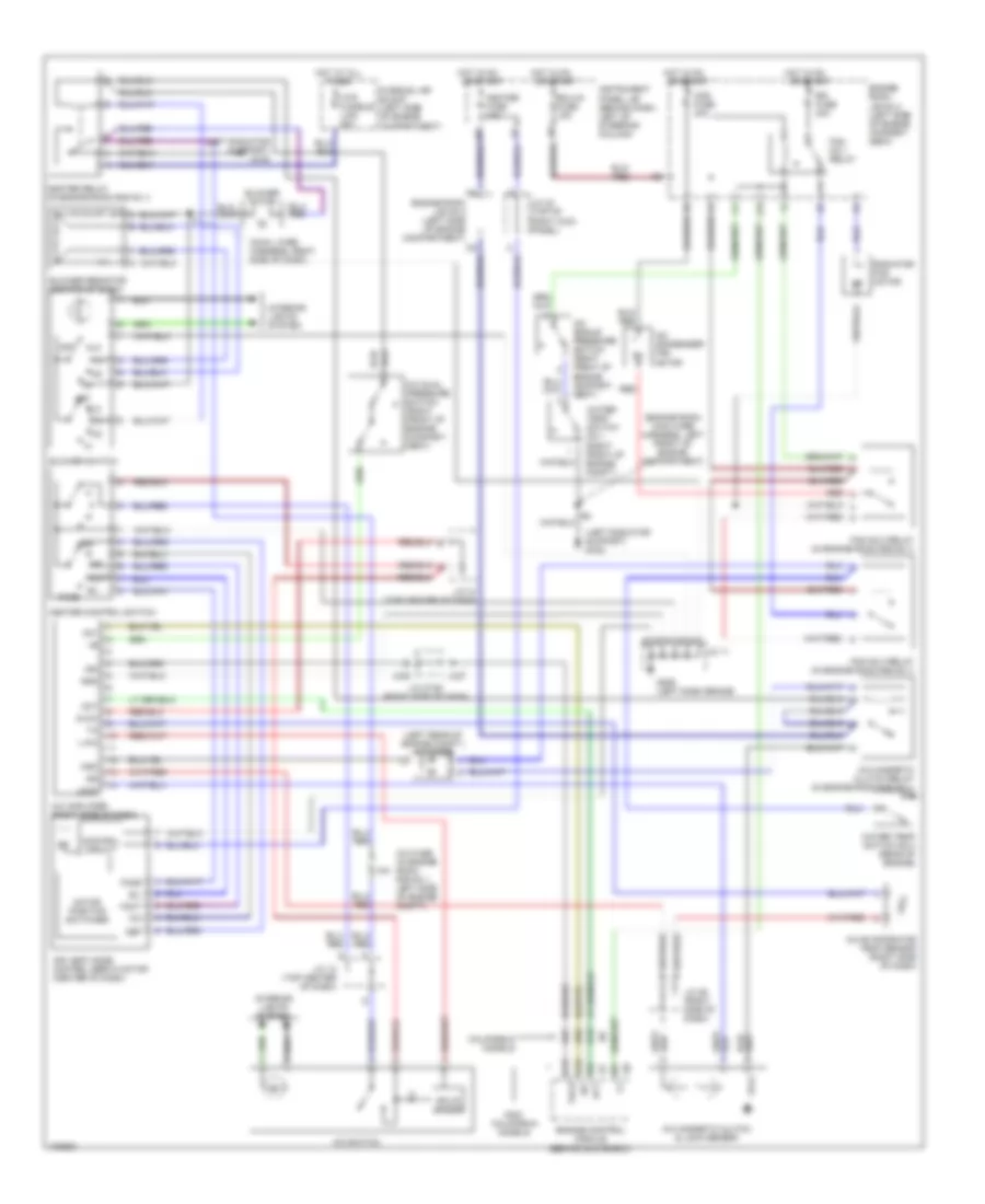
2.2L
2.2L, A/C Wiring Diagram for Toyota Camry CE 1998
 https://portal-diagnostov.com/license.html
Automotive Electricians Portal FZCO
Automotive Electricians Portal FZCO
https://portal-diagnostov.com/license.html
https://portal-diagnostov.com/license.html
Automotive Electricians Portal FZCO
Automotive Electricians Portal FZCO
List of elements for 2.2L, A/C Wiring Diagram for Toyota Camry CE 1998:
- (cowl wire harness, right side of dash)
- (engine room main wire harness, left front of engine compartment)
- (intake manifold) g131
- (left radiator support) g108
- 10a
- 2.2l engine w/engine immobilisor
- 2.2l engine w/o engine immobilisor
- A/c condenser fan motor
- A/c dual pressure switch (right front of engine compt.)
- A/c evaporator temp. sensor (right side of dash)
- A/c fuse (in engine room r/b no.1, left side of engine compartment)
- A/c magnetic clutch & lock sensor
- A/c magnetic clutch relay (in engine room r/b no.1)
- A/c single pressure switch (right front of engine compt.)
- A/c sw
- A/c switch
- A10
- A13
- A15
- A19
- A20
- A21
- Air vent mode control servo motor (center of dash)
- B/l
- B10
- B11
- Blower motor
- Blower resistor (center of dash)
- Blower switch
- C18
- C19
- Cds fuse 30a
- Control circuit
- Def
- Ecu-ig fuse 15a
- Engine control module (behind glove box)
- Engine room j/b no.2 (left side of engine compart- ment)
- Engine room j/b no.2 (left side of engine compartment)
- F/d
- Face
- Fan no.1 relay
- Fan no.2 relay (in engine room r/b no.1)
- Fan no.3 relay (in engine room r/b no.1)
- Foot
- Fusible link block (left side of engine compartment)
- G206 (left dash brace)
- Heater control switch
- Heater fuse 10a
- Heater relay (in engine room r/b no.1)
- Hot at all times
- Hot in on
- Hot in on or start
- Htr fusible link 50a
- Instrument panel j/b (behind dash, left of steering column)
- Interior lights system
- J/c 11
- J/c 12 (top center of dash)
- J/c 23 (right side of dash)
- J/c 32 (top of right kick panel)
- J/c 8 (lower left side of dash)
- Lock
- Lock in
- Mgc
- Motor position switches
- Off
- Or start
- Prs
- Radiator fan motor
- Rdi fuse 30a
- Red
- Solid state
- Thr
- Water temp switch no.1 (right front of engine compt.)
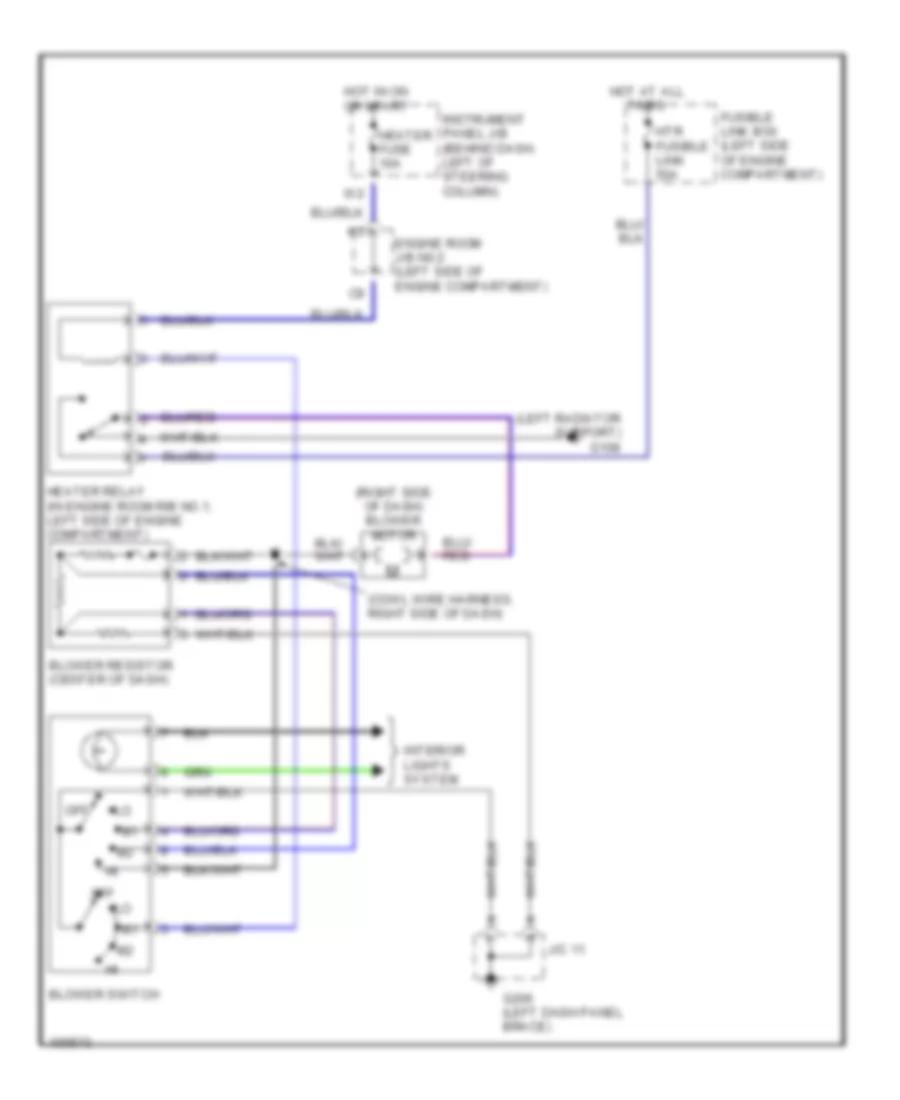
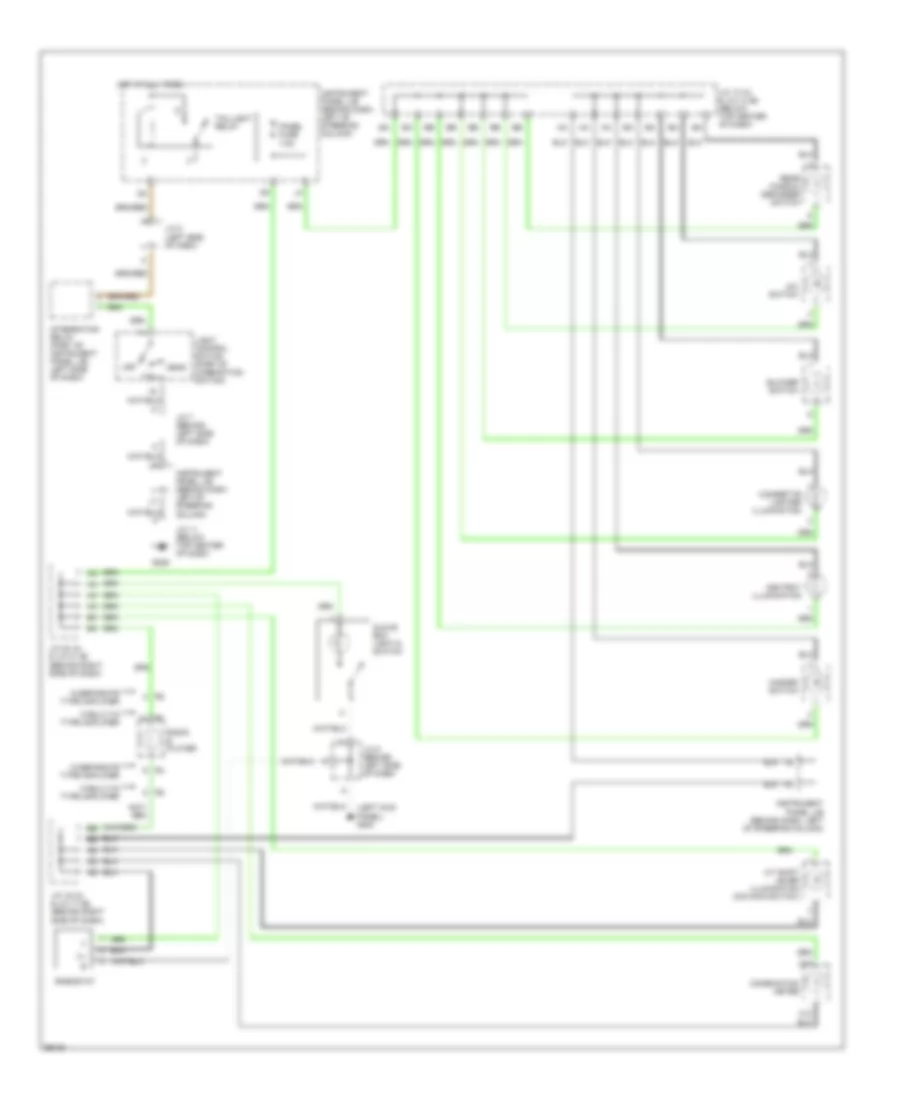
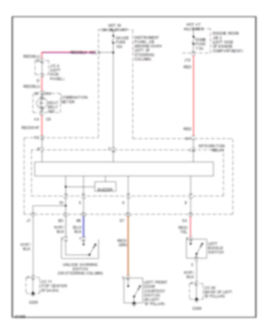
Heater Wiring Diagram for Toyota Camry CE 1998
List of elements for Heater Wiring Diagram for Toyota Camry CE 1998:
- (cowl wire harness, right side of dash)
- (left radiator support) g108
- (right side of dash) blower motor
- Blower resistor (center of dash)
- Blower switch
- Engine room j/b n0.2 (left side of engine compartment)
- Fusible link box (left side of engine compartment)
- G206 (left dash panel brace)
- Heater fuse 10a
- Heater relay (in engine room r/b no.1, left side of engine compartment)
- Hot at all times
- Hot in on or start
- Htr fusible link 50a
- Instrument panel j/b (behind dash, left of steering column)
- Interior lights system
- J/c 11
- Off
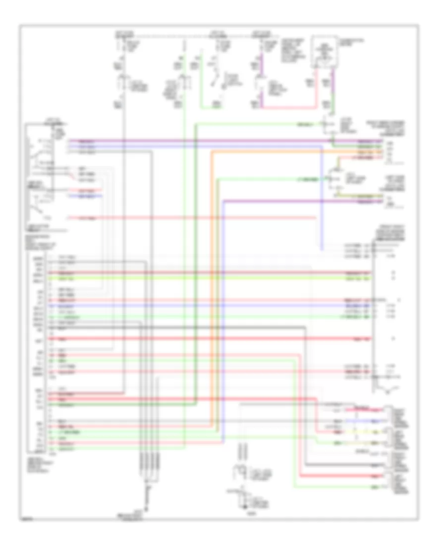
3.0L
3.0L, A/C Wiring Diagram for Toyota Camry CE 1998
List of elements for 3.0L, A/C Wiring Diagram for Toyota Camry CE 1998:
- (cowl wire harness, right side of dash)
- (engine room main wire harness, left front of engine compartment)
- (in engine room r/b no.1)
- (left radiator support) g108
- (left rear of engine compt.) a/c diode
- 10a
- A/c
- A/c amplifier (right side of dash)
- A/c condenser fan motor
- A/c dual pressure switch (right front of engine compart- ment)
- A/c evaporator temp sensor (right side of dash)
- A/c fuse (in engine room r/b no.1, left side of engine compt.)
- A/c magnetic clutch & lock sensor
- A/c magnetic clutch relay (in engine room r/b no.1)
- A/c single pressure switch (right front of engine compart- ment)
- A/c switch
- A13
- A16
- Ac1
- Act
- Air vent mode control servo motor (center of dash)
- B/l
- B13
- B25
- B27
- Blower motor
- Blower resistor (center of dash)
- Blower switch
- California models
- Cds fuse 30a
- Control circuit
- Def
- Ecu-ig fuse 15a
- Engine control module (behind glove box)
- Engine room j/b no.2 (left side of engine compart- ment)
- Engine room j/b no.2 (left side of engine compartment)
- F/d
- Face
- Fan no.1 relay
- Fan no.2 relay (in engine room r/b no.1)
- Fan no.3 relay
- Foot
- Fusible link block (left side of engine compartment)
- G206 (left dash brace)
- Gnd
- Heater control switch
- Heater fuse 10a
- Heater relay (in engine room r/b no.1)
- Hot at all times
- Hot in on
- Htr fusible link 50a
- Ign
- Instrument panel j/b (behind dash, left of steering column)
- Interior lights system
- J/c 11
- J/c 12 (top center of dash)
- J/c 27/28 (right side of dash)
- J/c 29 (right side of dash)
- J/c 32 (top of right kick panel)
- J13
- Jc27
- Jc28
- L-a/c
- Lock
- Mgc
- Motor position switches
- Non- california models
- Off
- Or start
- Radiator fan motor
- Rdi fuse 30a
- Red
- S-a/c
- Solid state
- Tach
- Water temp switch no.1 (right front of engine compt.)
- Water temp switch no.2 (rear of engine)
Heater Wiring Diagram for Toyota Camry CE 1998
List of elements for Heater Wiring Diagram for Toyota Camry CE 1998:
- (cowl wire harness, right side of dash)
- (left radiator support) g108
- (right side of dash) blower motor
- Blower resistor (center of dash)
- Blower switch
- Engine room j/b n0.2 (left side of engine compartment)
- Fusible link box (left side of engine compartment)
- G206 (left dash panel brace)
- Heater fuse 10a
- Heater relay (in engine room r/b no.1, left side of engine compartment)
- Hot at all times
- Hot in on or start
- Htr fusible link 50a
- Instrument panel j/b (behind dash, left of steering column)
- Interior lights system
- J/c 11
- Off
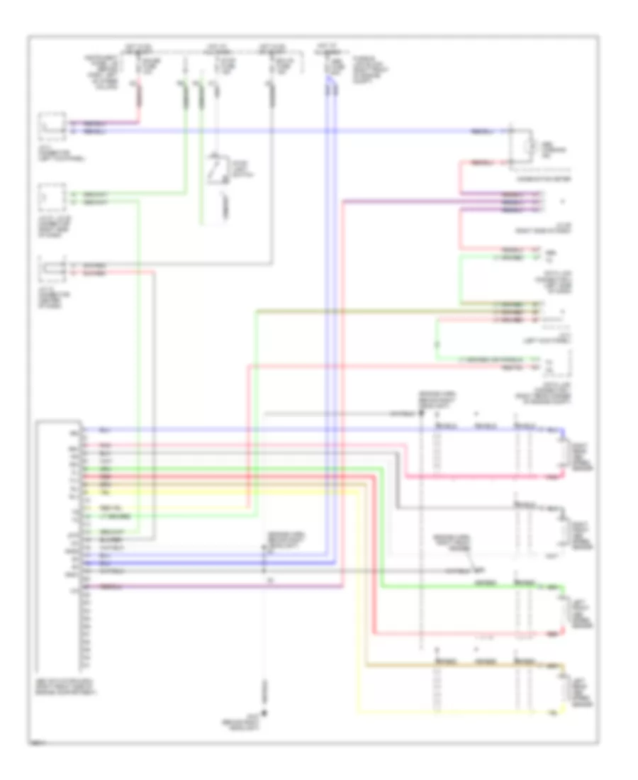
ANTI-LOCK BRAKES
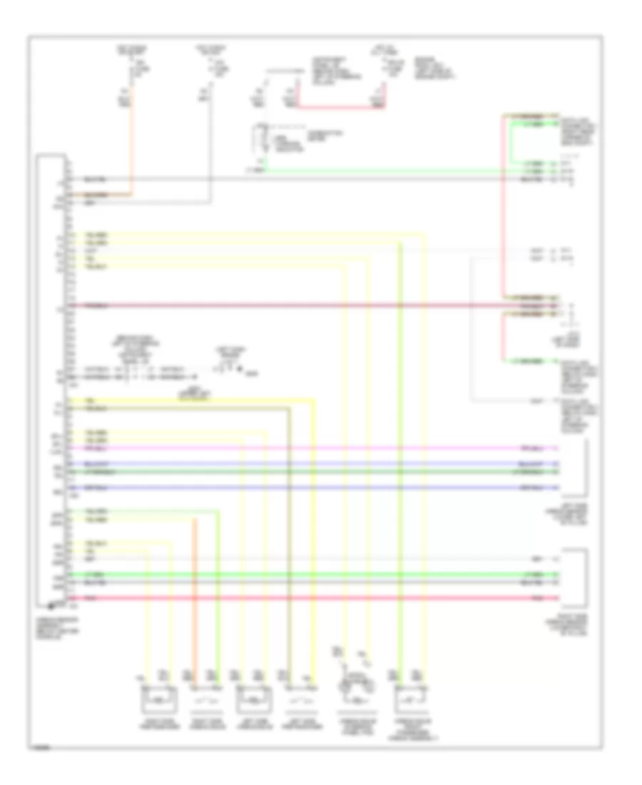
Anti-lock Brake Wiring Diagrams, TMC Made without Traction Control for Toyota Camry CE 1998
List of elements for Anti-lock Brake Wiring Diagrams, TMC Made without Traction Control for Toyota Camry CE 1998:
- (front right side of engine compartment) abs actuator
- (left side of dash) data link connector 2
- (right rear corner of engine compt) data link connector 1
- A18
- A19
- Abs
- Abs ecu (behind right side of glove box)
- Abs fuse 60a
- Abs motor relay
- Abs sol relay
- Abs warning ind
- Ast
- Combination meter
- D/g
- Ecu-ig fuse 15a
- Engine room r/b 3 (right front of engine compt)
- Fl+
- Fl-
- Fr+
- Fr-
- G107 (behind right headlight)
- G206
- Gauge fuse 10a
- Gnd
- Gnd2
- Hot at all times
- Hot in on or start
- Ig1
- Instrument panel j/b (behind dash, left of steering column)
- J/c 11 (center of dash)
- J/c 12 (center of dash)
- J/c 27, j/c 28 (right side of dash)
- J/c 29 (right side of dash)
- J/c 3 (left side of dash)
- J/c 4 (above left kick panel)
- J/c 7, j/c 8 (left side of dash)
- Left front abs speed sensor
- Left rear abs speed sensor
- Pnk
- Red
- Right front abs speed sensor
- Right rear abs speed sensor
- Rl+
- Rl-
- Rr+
- Rr-
- Sflh
- Sflr
- Sfrh
- Sfrr
- Shield
- Srlh
- Srlr
- Srrh
- Srrr
- Stop fuse 15a
- Stop light switch
- Stp
Anti-lock Brake Wiring Diagrams, TMM Made without Traction Control for Toyota Camry CE 1998
List of elements for Anti-lock Brake Wiring Diagrams, TMM Made without Traction Control for Toyota Camry CE 1998:
- (engine harn, behind right headlight) e1
- (engine harn, right front fender)
- Abs
- Abs actuator & ecu (right front side of engine compartment)
- Abs fuse 60a
- Abs warning ind
- Combination meter
- Data link connector 1 (right rear corner of engine compt)
- Data link connector 2 (left side of dash)
- Ecu-ig fuse 15a
- Fl+
- Fl-
- Fr+
- Fr-
- Fusible link block (right front of engine compt)
- G107 (behind right headlight)
- Gauge fuse 10a
- Gnd1
- Gnd2
- Hot at all times
- Hot in on or start
- Ig1
- Instrument panel j/b (behind dash, left of steer column)
- J/c 12 connector (center of dash)
- J/c 27, j/c 28 connector (right side of dash)
- J/c 29 (right side of dash)
- J/c 3 (left kick panel)
- J/c 4 connector (left kick panel)
- Left front abs speed sensor
- Left rear abs speed sensor
- Pnk
- Red
- Right front abs speed sensor
- Right rear abs speed sensor
- Rl+
- Rl-
- Rr+
- Rr-
- Shield
- Stop fuse 15a
- Stop- light switch
- Stp
Anti-lock Brake Wiring Diagrams, with Traction Control for Toyota Camry CE 1998
List of elements for Anti-lock Brake Wiring Diagrams, with Traction Control for Toyota Camry CE 1998:
- 1998-99
- A10
- A11
- A12
- A15
- A16
- A17
- Abs
- Abs & traction actuator (front right side of engine compartment)
- Abs & traction ecu (behind right side of dash)
- Abs fuse 60a
- Abs ind
- Abs motor relay
- Abs sol relay
- Ast
- C10
- Combination meter
- Csw
- D/g
- Data link connector 1 (right rear corner of engine compt)
- Data link connector 2 (left side of dash)
- Ecu-ig fuse 15a
- Efi+
- Efi-
- Engine control module (behind glove box)
- Engine room r/b 3 (right front of engine compt)
- Fl+
- Fl-
- Fr+
- Fr-
- G107 (behind right headlight)
- G206
- Gauge fuse 10a
- Gnd1
- Gnd2
- Gnd3
- Hot at all times
- Hot in on or start
- Ig1
- Ind
- Instrument panel j/b (behind dash, left of steering column)
- J/c 11 (center of dash)
- J/c 12 (center of dash)
- J/c 27, j/c 28 (right side of dash)
- J/c 29 (right side of dash)
- J/c 3 (above left kick panel)
- J/c 32 (behind right side of dash)
- J/c 4 (above left kick panel)
- J/c 7, j/c 8 (left side of dash)
- Left front abs speed sensor
- Left rear abs speed sensor
- Neo
- Red
- Right front abs speed sensor
- Right rear abs speed sensor
- Rl+
- Rl-
- Rr+
- Rr-
- Sflh
- Sflr
- Sfrh
- Sfrr
- Shield
- Slip ind
- Smc1
- Smc2
- Src1
- Src2
- Srlh
- Srlr
- Srrh
- Srrr
- Stop fuse 15a
- Stop- light switch
- Stp
- Trac off ind
- Traction off switch (left side of dash)
- Trc
- Trc+
- Trc-
ANTI-THEFT
Forced Entry Wiring Diagram for Toyota Camry CE 1998
List of elements for Forced Entry Wiring Diagram for Toyota Camry CE 1998:
- (behind left headlight)
- (behind left side of dash) junction connector j/c 5
- (behind left side of dash, taped to harness) dome diode
- (right side of radio) junction connector j/c 16/ j/c 17
- +b1
- +b2
- A10
- A11
- A12
- A13
- A14
- A15
- A16
- A17
- A18
- A19
- A20
- A21
- A22
- B10
- B11
- B12
- C10
- Combination meter
- Courtesy diode (behind right side of dash, taped to harness)
- Cty
- Dome fuse 7.5a
- Door fuse 25a
- Door locks system
- Dswd
- Dswh
- Dswl
- Dswp
- E (grd)
- Ecu-ig fuse 15a
- Engine hood courtesy switch
- Engine room j/b 2 (left side of engine compt)
- Exterior lights system
- G106
- G200 (left kick panel)
- G302 (below center console)
- G407 (center rear of trunk)
- Head
- Headlights system
- Horn
- Horn fuse 10a
- Horns system
- Hot at all times
- Hot in run or start
- Ind
- Instrument panel j/b (behind left side of dash)
- Integration relay
- J12
- Junction connector j/c 33/ j/c 34 (right end (right end of dash)
- Junction connector j/c 9/ j/c 10 (upper center of dash)
- Ksw
- Left front door courtesy switch
- Left rear door courtesy switch
- Lswd
- Lswp
- Lswr
- Lug
- Luggage compartment key unlock switch
- Luggage compartment light switch
- Pani
- Red
- Right front door courtesy switch
- Right rear door courtesy switch
- S12
- Tail
- Theft deter- rent indic
- Theft deterrent ecu (behind top right side of dash)
- Theft deterrent horn (on right rear of engine compt)
- Ul2
- Ul3
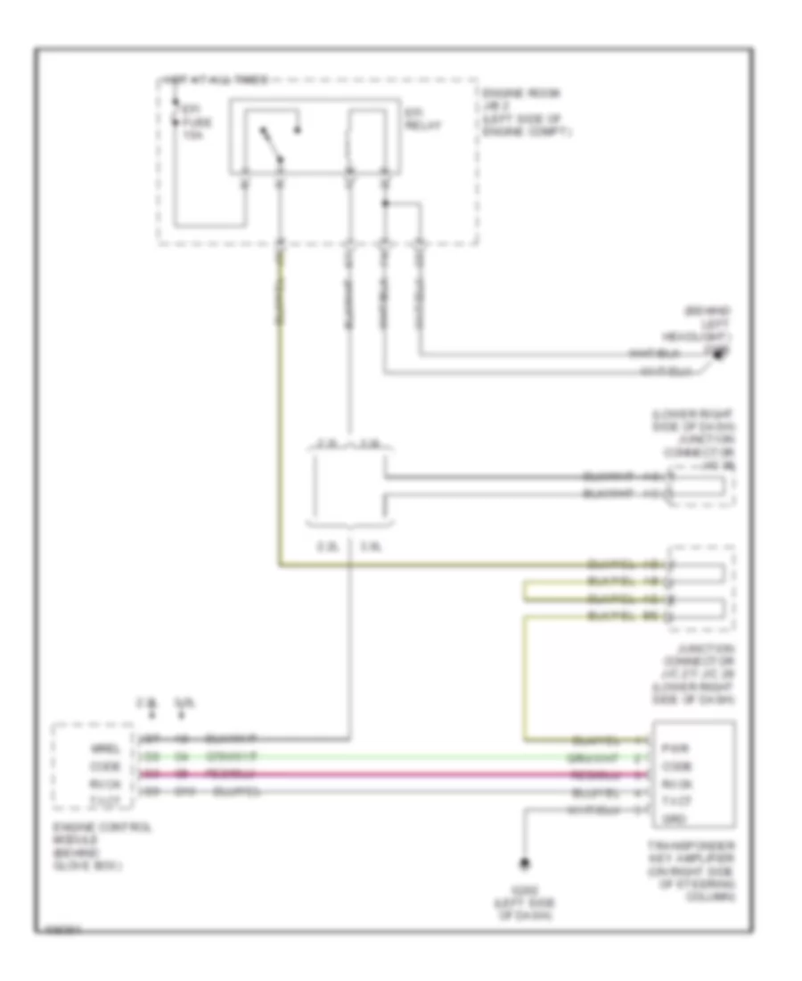
Immobilizer Wiring Diagram for Toyota Camry CE 1998
List of elements for Immobilizer Wiring Diagram for Toyota Camry CE 1998:
- (behind left headlight) g106
- (lower right side of dash) junction connector j/c 35
- 2.2l
- 3.0l
- C10
- Code
- Efi fuse 15a
- Efi relay
- Engine control module (behind glove box)
- Engine room j/b 2 (left side of engine compt)
- G202 (left side of dash)
- Grd
- Hot at all times
- Junction connector j/c 27/ j/c 28 (lower right side of dash)
- Mrel
- Pwr
- Rxck
- Transponder key amplifier (on right side of steering column)
- Txct
COMPUTER DATA LINES
Computer Data Lines for Toyota Camry CE 1998
List of elements for Computer Data Lines for Toyota Camry CE 1998:
- (on intake manifold) g131
- (w/o traction)
- 2.2l w/ immobilizer
- 2.2l w/o immobilizer
- 3.0l w/ immobilizer
- 3.0l w/o immobilizer
- A/d
- A15
- A16
- A19
- Abs
- Abs & traction ecu (w/ traction only) (right side of engine compt)
- Abs actuator and ecu (usa built) (right front of engine compt)
- Abs ecu (japan built) (right side of glove box)
- Abs solenoid relay (engine room relay block 3)
- Airbag sensor assembly (below center console)
- Cruise control ecu (behind left side of dash)
- Data link connector 1 (right rear corner of engine compt)
- Data link connector 2 (under left side of dash)
- Data link connector 3 (under left side of dash)
- E11
- Efi fuse 15a
- Efi main relay
- Engine control module (behind glove box)
- Engine room j/b 2 (left side of engine compartment)
- G206
- Hot at all times
- I/p junction block (behind lower left side of dash)
- J10
- Jumper wire
- Junction connector j11 (behind left side of radio)
- Junction connector j19 (2.2l) connector j20 (3.0l) (right end of dash)
- Junction connector j2 (left end of dash)
- Junction connector j23 (2.2l) connector j23 (3.0l) (behind right side of dash)
- Junction connector j27/j28 (behind right side of dash)
- Junction connector j29 (right end of dash)
- Junction connector j3 (left end of dash)
- Junction connector j32 (behind right side of dash)
- Junction connector j7/j8 (behind left side of dash)
- Nca
- Obd fuse 7.5a
- Sil
- Te1
- Trc
COOLING FAN
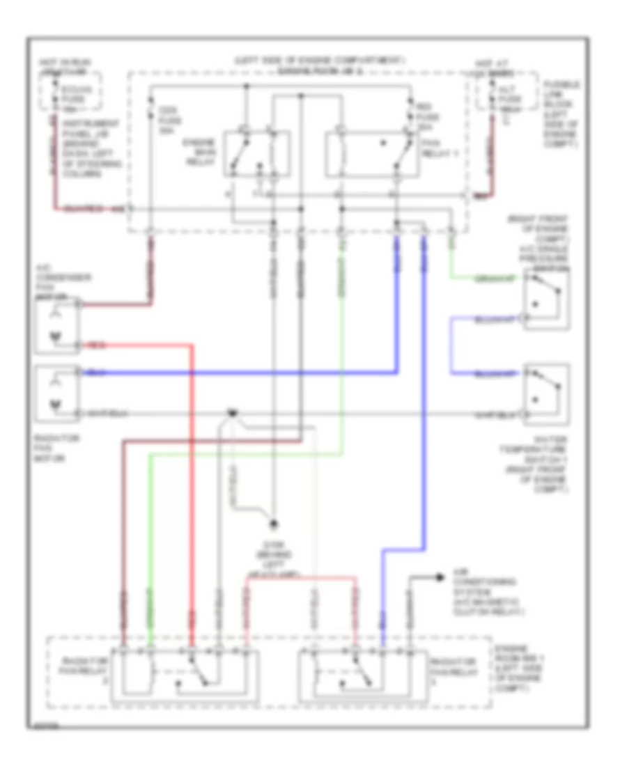
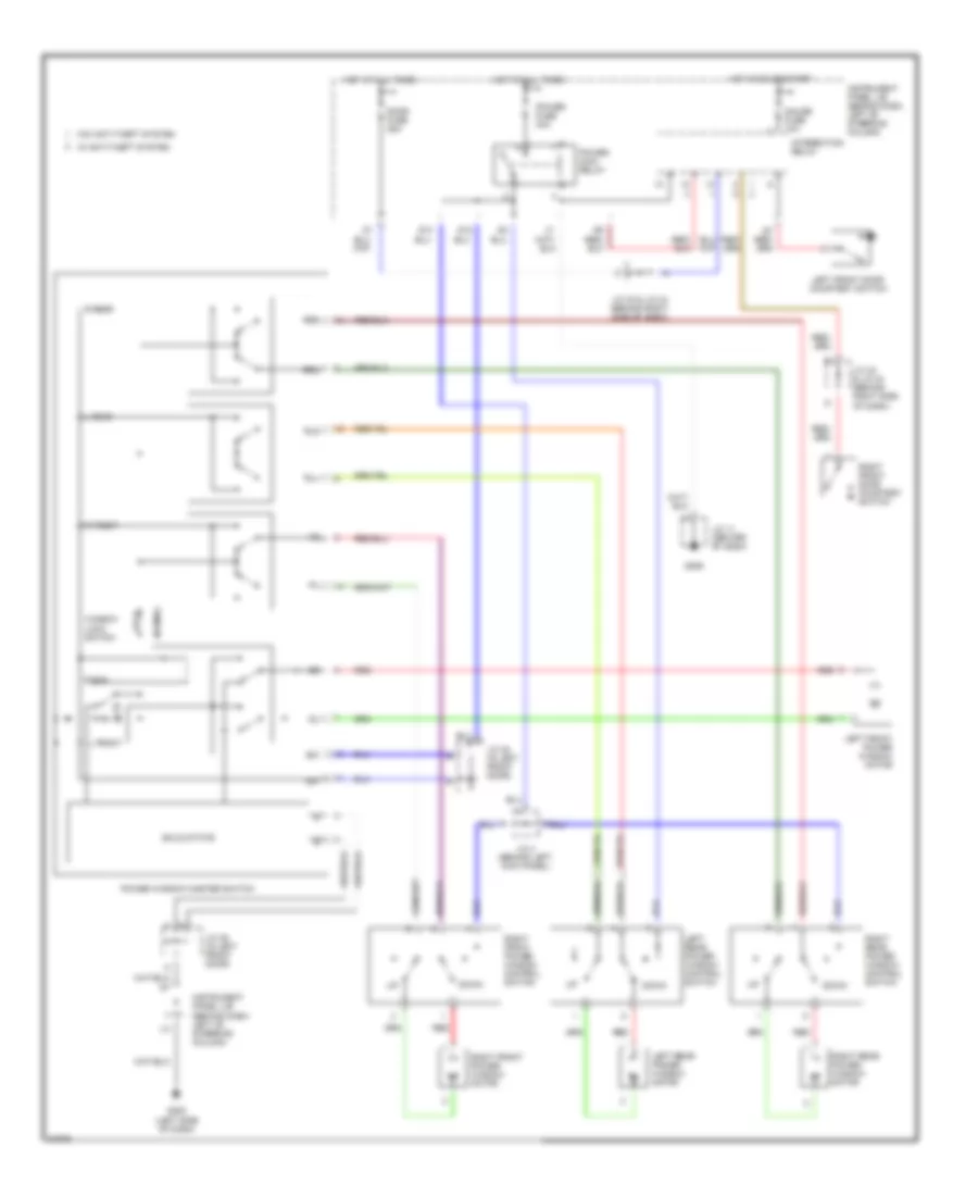
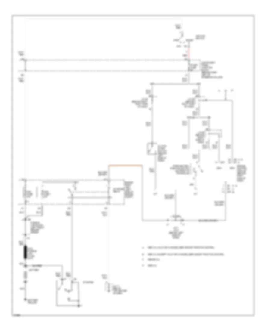
2.2L
2.2L, Cooling Fan Wiring Diagram for Toyota Camry CE 1998
List of elements for 2.2L, Cooling Fan Wiring Diagram for Toyota Camry CE 1998:
- (left side of engine compartment) engine room j/b 2
- (right front of engine compt) a/c single pressure switch
- A/c condenser fan motor
- Air conditioning system (a/c magnetic clutch relay)
- Alt fuse 100a f7
- Cds fuse 30a
- Ecu-ig fuse 15a
- Engine main relay
- Engine room r/b 1 (left side of engine compt)
- Fan relay 1
- Fusible link block (left side of engine compt)
- G106 (behind left headlamp)
- Hot at all times
- Hot in run or start
- Instrument panel j/b (behind dash, left of steering column)
- Radiator fan motor
- Radiator fan relay
- Rdi fuse 30a
- Red
- Water temperature switch 1 (right front of engine compt)
3.0L
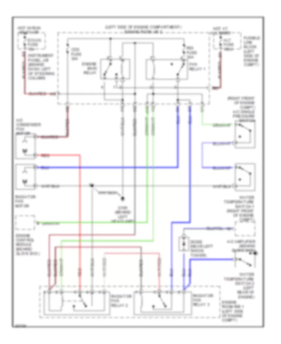
3.0L, Cooling Fan Wiring Diagram for Toyota Camry CE 1998
List of elements for 3.0L, Cooling Fan Wiring Diagram for Toyota Camry CE 1998:
- (left side of engine compartment) engine room j/b 2
- (right front of engine compt) a/c single pressure switch
- A/c amplifier (behind glove box)
- A/c condenser fan motor
- Alt fuse 100a
- Cds fuse 30a
- Diode (near left shock tower)
- Ecu-ig fuse 15a
- Engine control module (behind glove box)
- Engine main relay
- Engine room r/b 1 (left side of engine compt)
- Fan relay 1
- Fusible link block (left side of engine compt)
- G106 (behind left headlamp)
- Hot at all times
- Hot in run or start
- Instrument panel j/b (behind dash, left of steering column)
- J13
- Radiator fan motor
- Radiator fan relay 2
- Radiator fan relay 3
- Rdi fuse 30a
- Red
- Water temperature switch 1 (right front of engine compt)
- Water temperature switch 2 (left rear of engine)
CRUISE CONTROL
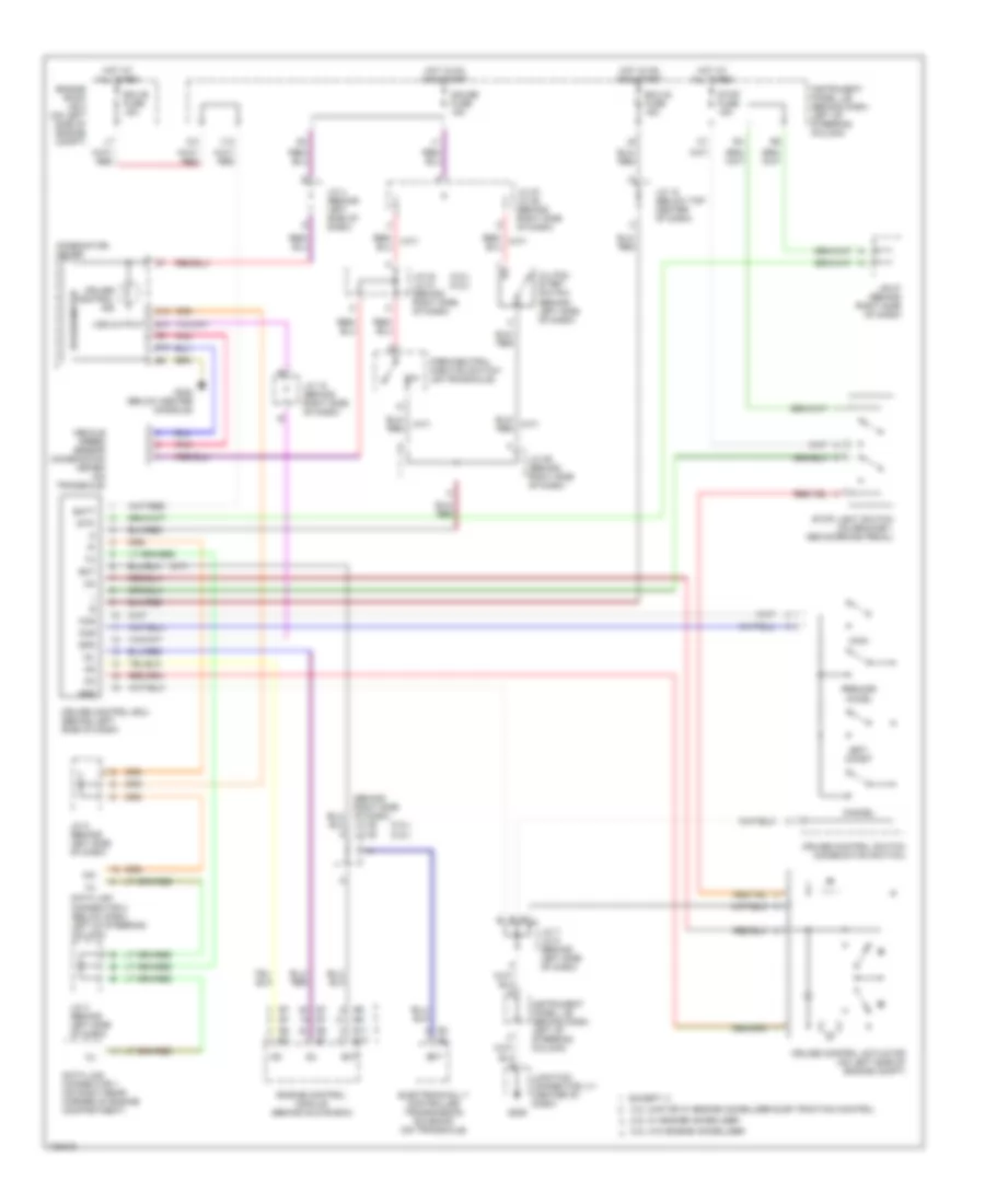
Cruise Control Wiring Diagram for Toyota Camry CE 1998
List of elements for Cruise Control Wiring Diagram for Toyota Camry CE 1998:
- (3.0l) (2.2l)
- (a/t)
- (behind right side of dash) j/c 26 j/c 25 a
- 2.2l w/ engine immobilizer
- 2.2l w/o engine immobilizer
- 3.0l caif or w/ engine immobilizer &/or traction control
- A/d
- B14
- B15
- Batt
- C10
- Cancel
- Ccs
- Clutch start switch (behind left side of dash)
- Cms
- Combination meter
- Cruise control actuator (on left side of engine compt)
- Cruise control ecu (behind left side of dash)
- Cruise control ind
- Cruise control switch (combination switch)
- Data link connector 1 (on right rear corner of engine compartment)
- Data link connector 2 (below dash, left of steering column)
- E10
- E11
- Ect
- Ecu-b fuse 15a
- Ecu-ig fuse 15a
- Electronically controlled transmission solenoid (on transaxle)
- Engine control module (behind glove box)
- Engine room j/b 2 (on left side of engine compt)
- Except
- G206
- G302 (below center console)
- Gauge fuse 15a
- Gnd
- Hot at all times
- Hot in on and start
- Idl
- Instrument panel j/b (behind dash, left of steering column)
- J/b 27 (behind right side of dash)
- J/c 12 (below top center of dash)
- J/c 15 (behind right side of dash)
- J/c 2 (behind left side of dash)
- J/c 24 j/c 21 (behind right side of dash)
- J/c 27, j/c 28 (behind right side of dash)
- J/c 29 (behind right side of dash)
- J/c 3 (behind left side of dash)
- J/c 4 (behind left side of dash)
- J/c 7, j/c 8 (behind left side of dash)
- Junction connector j11 (center of dash)
- Main
- P/n
- Park/neutral position switch (on transaxle)
- Pnk
- Red
- Red/ (a/t)
- Resume/ accel
- Set/ coast
- Spd
- Speedometer
- Stop fuse 15a
- Stop light switch (on bracket, above brake pedal)
- Stp-
- V10
- Vehicle speed sensor (combination meter) (on transaxle)
- Vss output
DEFOGGERS
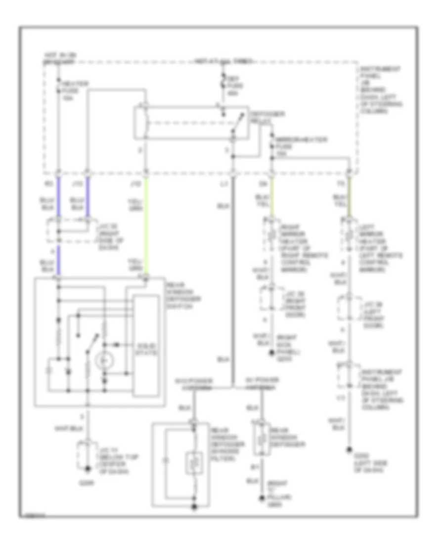
Defogger Wiring Diagram for Toyota Camry CE 1998
List of elements for Defogger Wiring Diagram for Toyota Camry CE 1998:
- (right "c" pillar) g905
- Def fuse 40a
- Defogger relay
- G202 (left side of dash)
- G206
- Heater fuse 10a
- Hot at all times
- Hot in on or start
- Instrument panel j/b (behind dash, left of steering column)
- Instrument panel j/b (behind dash, left of steering column)
- J/c 11 (below top center of dash)
- J/c 32 (right side of dash)
- J/c 38 (left front door)
- J/c 39 (right front door)
- J12
- J13
- Left mirror heater (part of left remote control mirror)
- Mirror-heater fuse 10a
- Rear window defogger
- Rear window defogger (w/noise filter)
- Rear window defogger switch
- Right mirror heater (part of right remote control mirror)
- Solid state
- W/ power antenna
- W/o power antenna
ENGINE PERFORMANCE
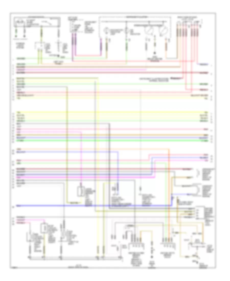
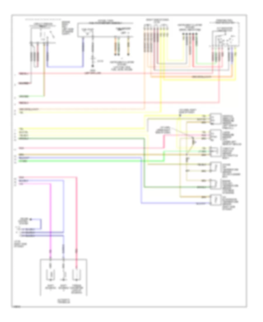
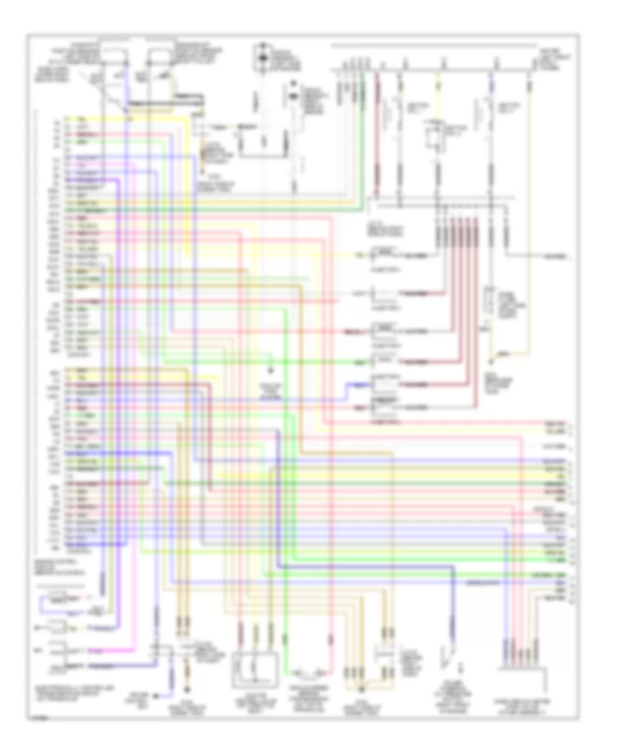
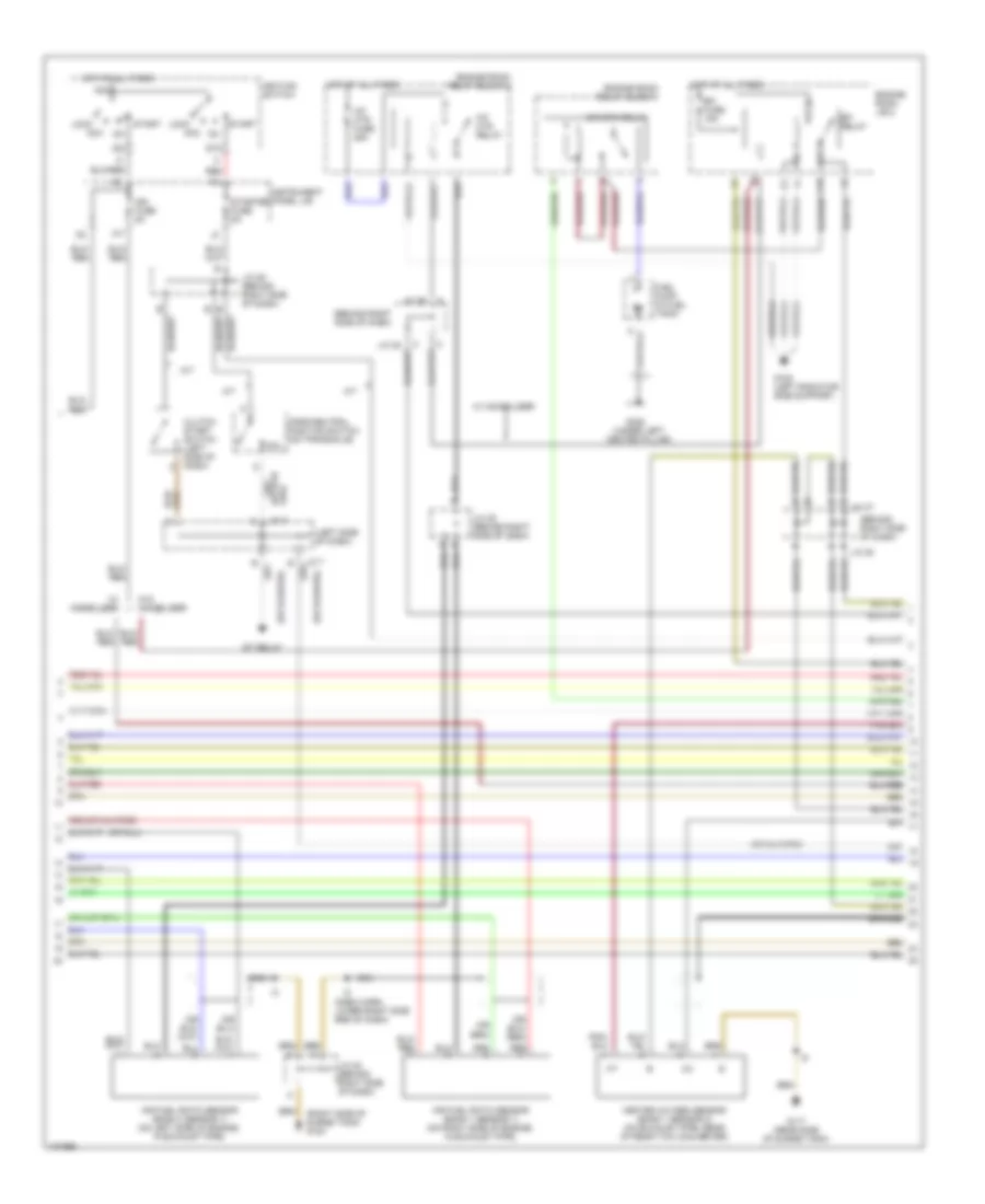
2.2L
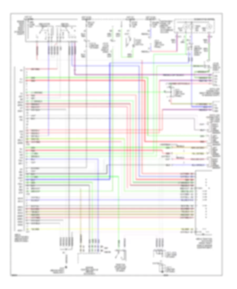
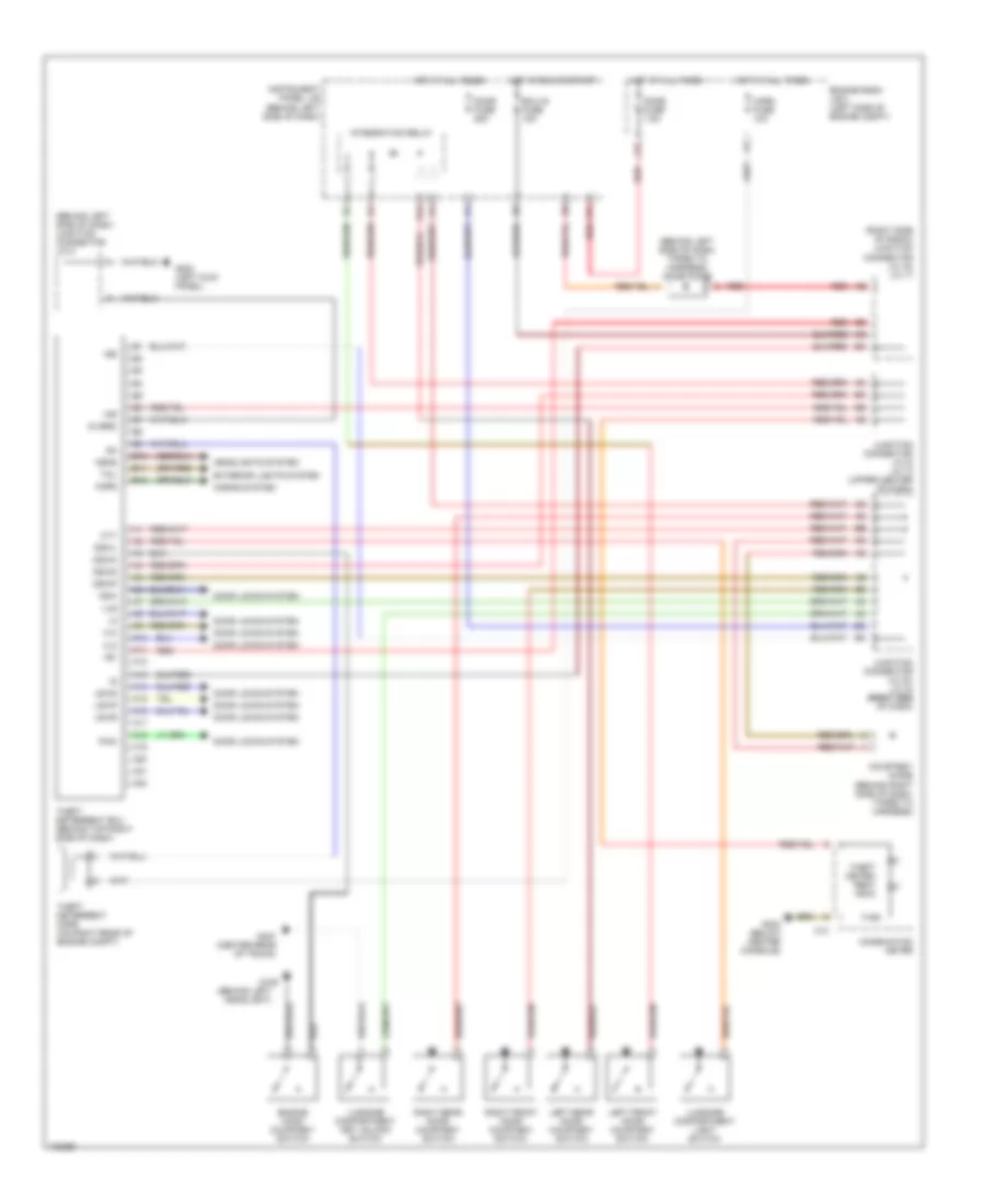
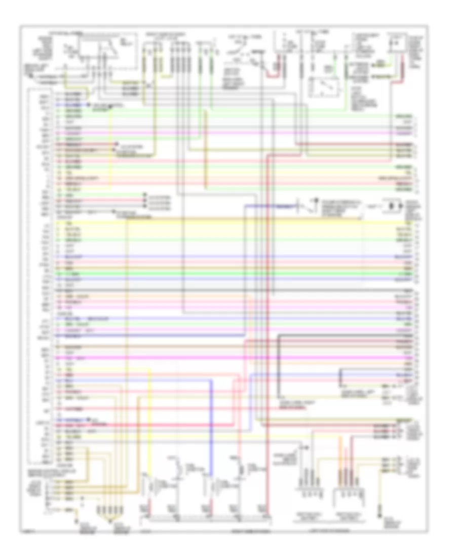
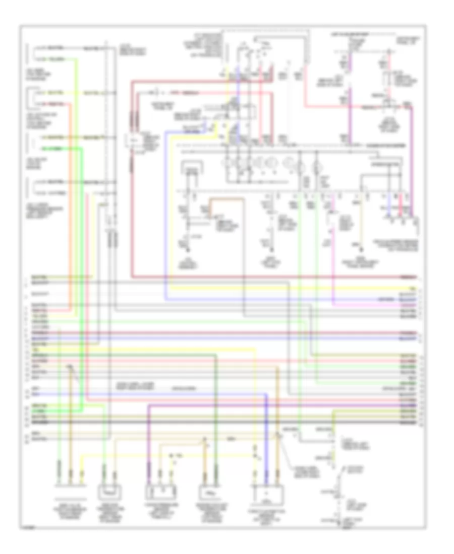
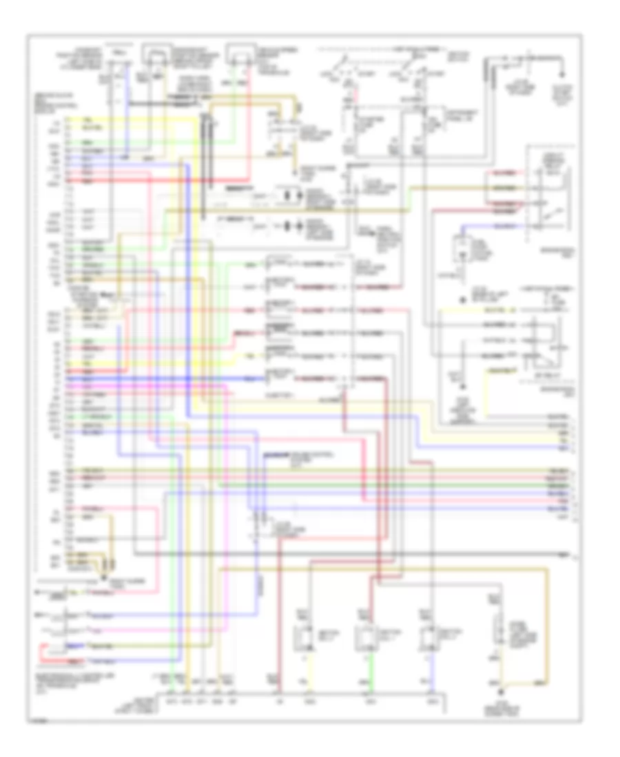
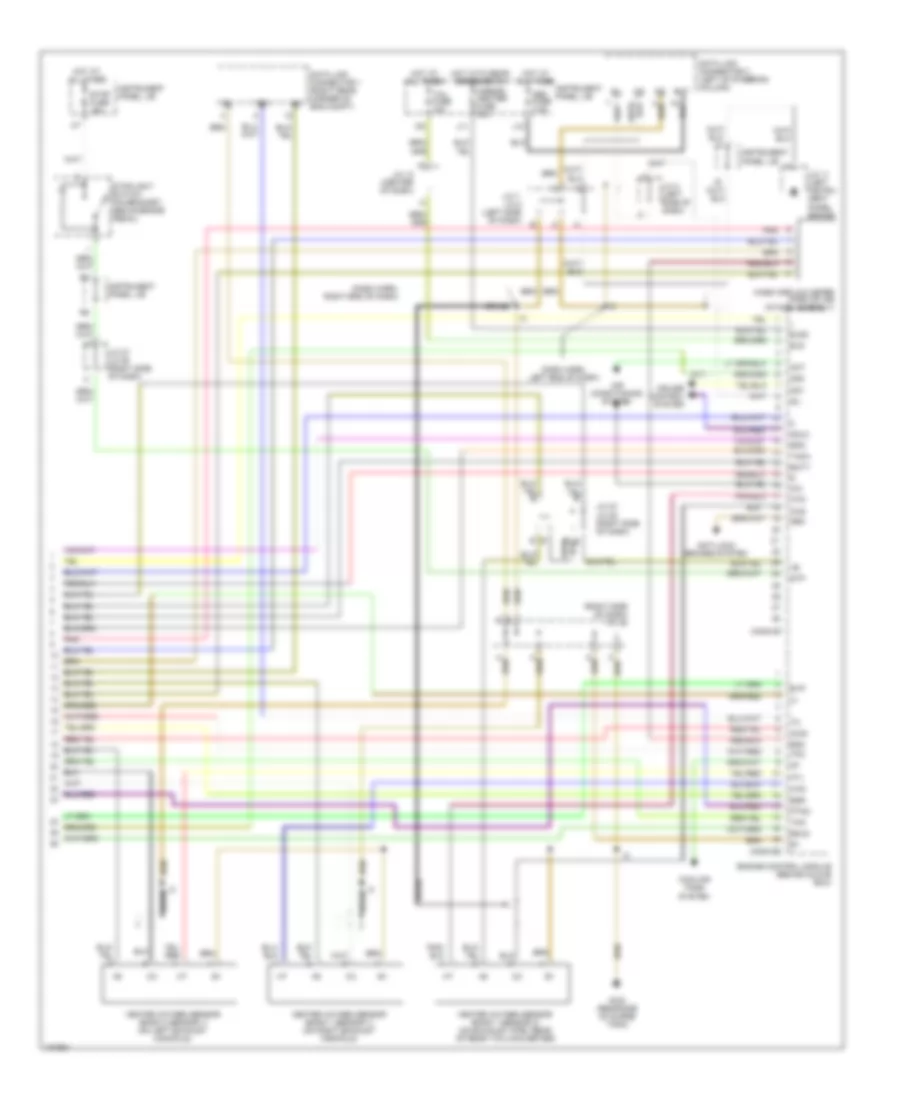
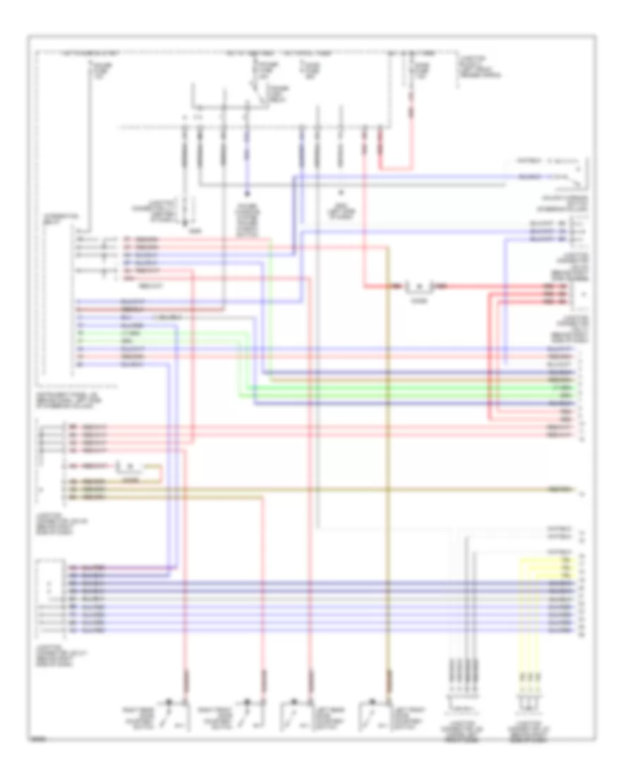
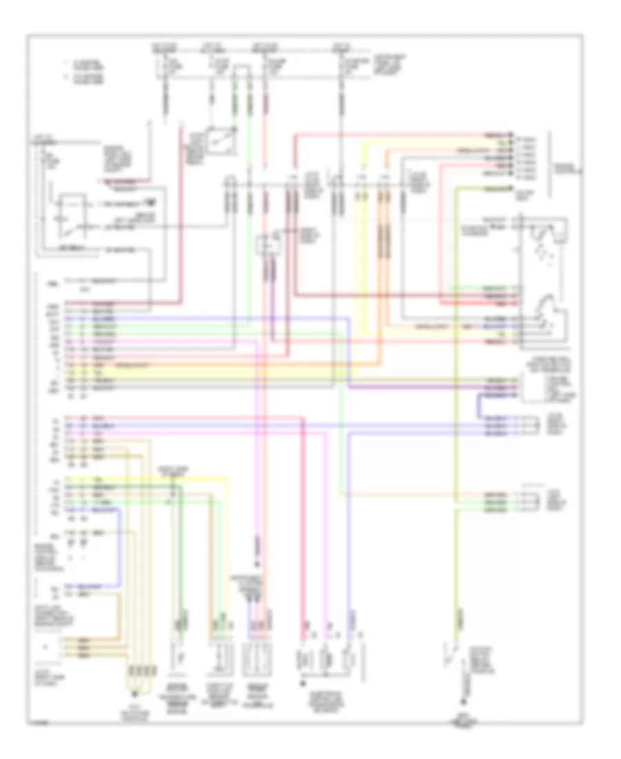
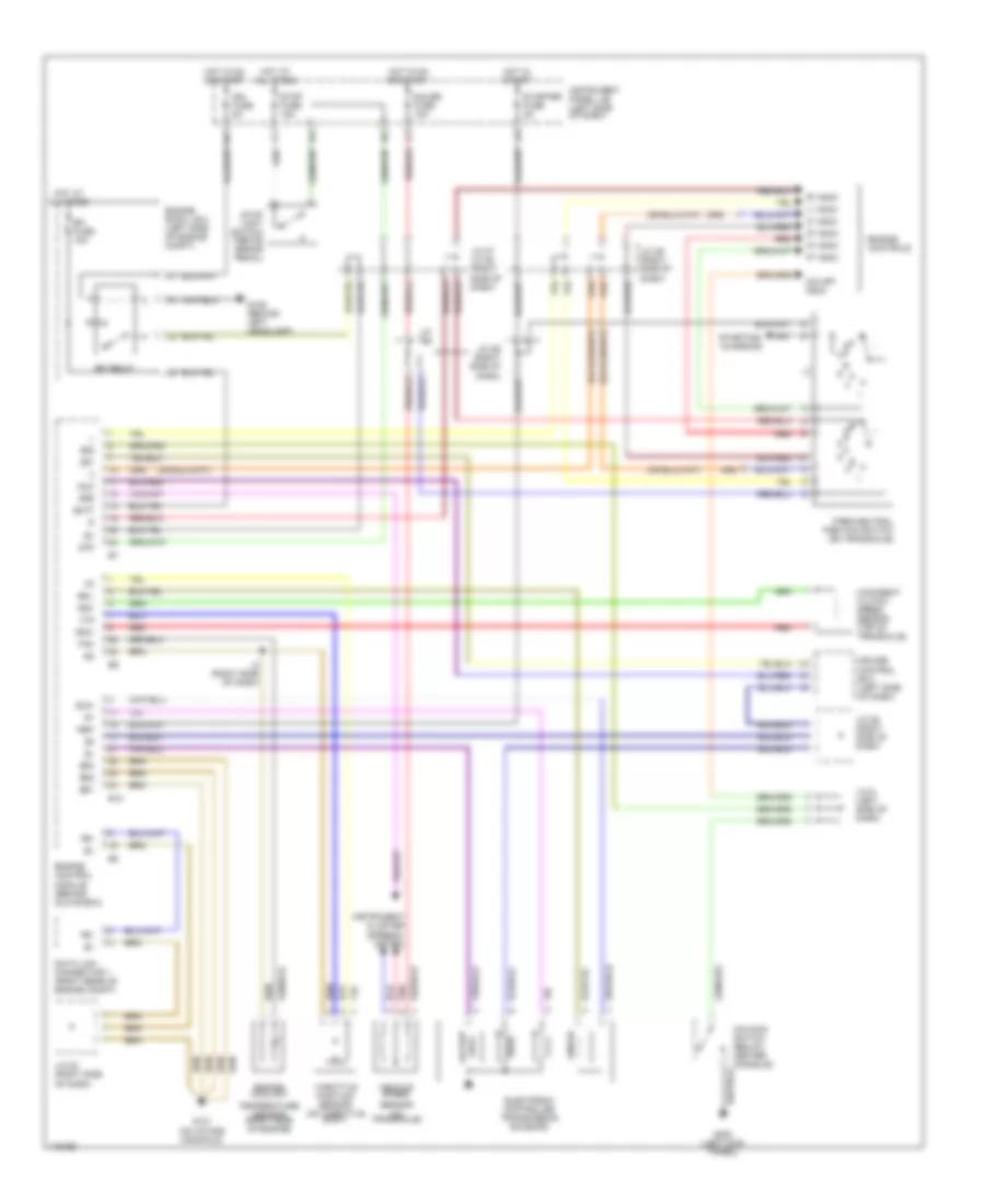
2.2L, Engine Performance Wiring Diagrams, with Immobilizer (1 of 3) for Toyota Camry CE 1998
List of elements for 2.2L, Engine Performance Wiring Diagrams, with Immobilizer (1 of 3) for Toyota Camry CE 1998:
- (a/t)
- (behind left headlamp) g106
- (calif)
- (dash harn, left end of dash)
- (dash harn, right end of dash)
- (eng harn, left front fender)
- (exc calif)
- (left side of engine)
- (right side of dash)
- (right side of dash) j/c 27, j/c 28
- A j27
- A/c sw
- A/c system
- Acc
- Af+
- Af-
- Am2
- B j27
- Batt
- C j28
- C10
- Conn e7
- Conn e8
- Conn e9
- Cruise control system
- Defogger system
- E01
- E02
- E03
- E04
- Efi fuse 15a
- Efi relay
- Egr
- Els
- Engine control module (behind glove box)
- Engine room r/b 2 (left side of engine compt)
- Evp
- Exterior lights system
- Fuel injector
- G115 (rear of engine)
- Gnd
- Hot at all times
- Ht1
- Ht2
- Htaf
- I2 (dash harn, behind glove blox)
- Idle-up diode (right side of dash taped to harn)
- Idlo
- Ig2
- Igf
- Ign fuse 5a
- Ignition coil/ igniter 1
- Ignition coil/ igniter 2
- Ignition switch
- Igsw
- Igt
- Igt1
- Igt2
- Instrument panel j/b (left of steering column)
- Iscc
- Isco
- J/c 19 (right side of dash)
- J/c 21
- J/c 23 (right side of dash)
- J/c 25 (right side of dash)
- J/c 7
- J/c 7, j/c 8 (left side of dash)
- J/c 8
- Knk
- Lock
- Lock in
- Mgc
- Nsw
- Od1
- Od2
- Ox1
- Ox2
- Pim
- Pnk
- Power steering oil pressure switch (right rear of engine)
- Prs
- Ps sw
- Ptnk
- Red
- Sil
- Spd
- Sta
- Start
- Starting/ charging system
- Stop fuse 15a
- Stop light switch (on bracket above brake pedal)
- Stp
- Tach
- Te1
- Tha
- Thr
- Thw
- Tpc
- Vta
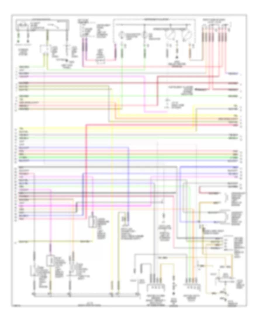
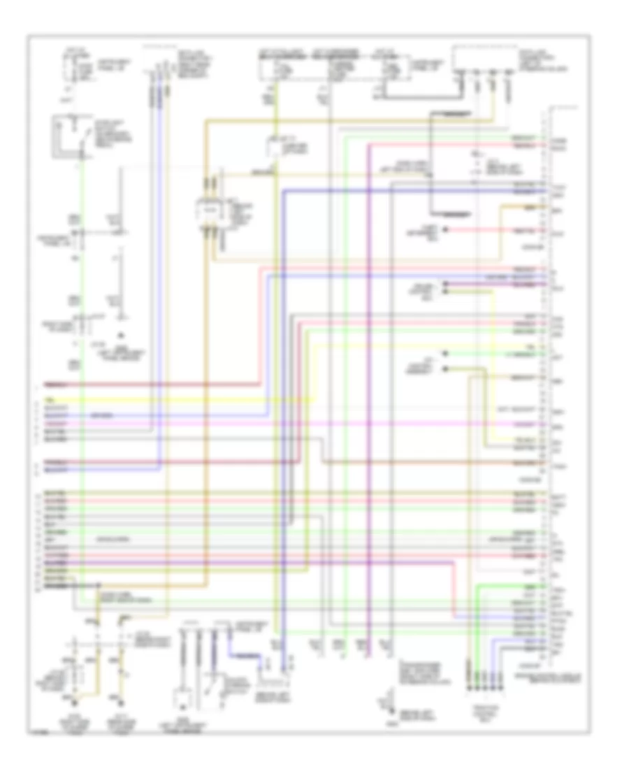
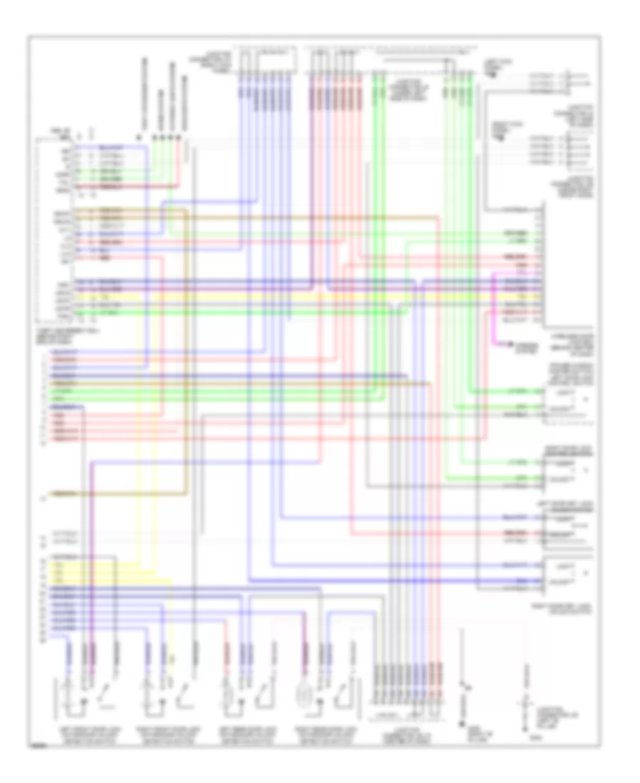
2.2L, Engine Performance Wiring Diagrams, with Immobilizer (2 of 3) for Toyota Camry CE 1998
List of elements for 2.2L, Engine Performance Wiring Diagrams, with Immobilizer (2 of 3) for Toyota Camry CE 1998:
- (left kick panel)
- (left kick panel) j/c 4
- (left side of engine compt)
- (right side of dash) j/c 27, j/c 28
- A/t shift lever illumination lamp
- Af+
- Af-
- Air fuel ratio sensor (calif)
- C j27
- C10
- Calif
- Camshaft position sensor (right front of engine)
- Crankshaft position sensor (left front of engine)
- Data link connector (partial) (left of steering column)
- Data link connector 1 (partial) (right rear corner of engine compt)
- Egr vacuum solenoid valve (upper right front of engine)
- Evap vacuum solenoid valve (a/t) (left side of engine compt)
- Exc calif
- F j28
- G115 (rear of engine)
- G200
- G302 (below center console)
- Gauge fuse 10a
- Heated oxygen sensor (bank1, sensor 1) (exc calif) (rt side of eng)
- Heated oxygen sensor bank 1, sensor 2 (all) (rear of twc conv)
- Hot in on or start
- Idle air control valve (on throttle body)
- Instrument cluster
- Instrument cluster system (r-prndl indicator)
- Instrument panel j/b (left of steering column)
- Interior lights system
- J/c 15 (right side of dash)
- J/c 19 (right side of dash)
- J/c 23 (left side of dash)
- J/c 5 (left side of dash)
- J/c 6 (left side of dash)
- Malfunction indicator lamp
- Nca
- O/d main switch
- O/d off indicator
- Pnk
- Speedometer
- Tachometer
- Vapor pressure sensor vsv (a/t)
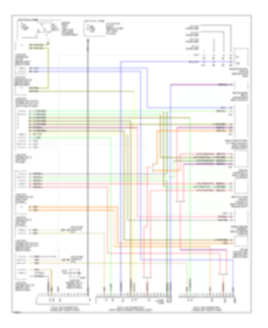
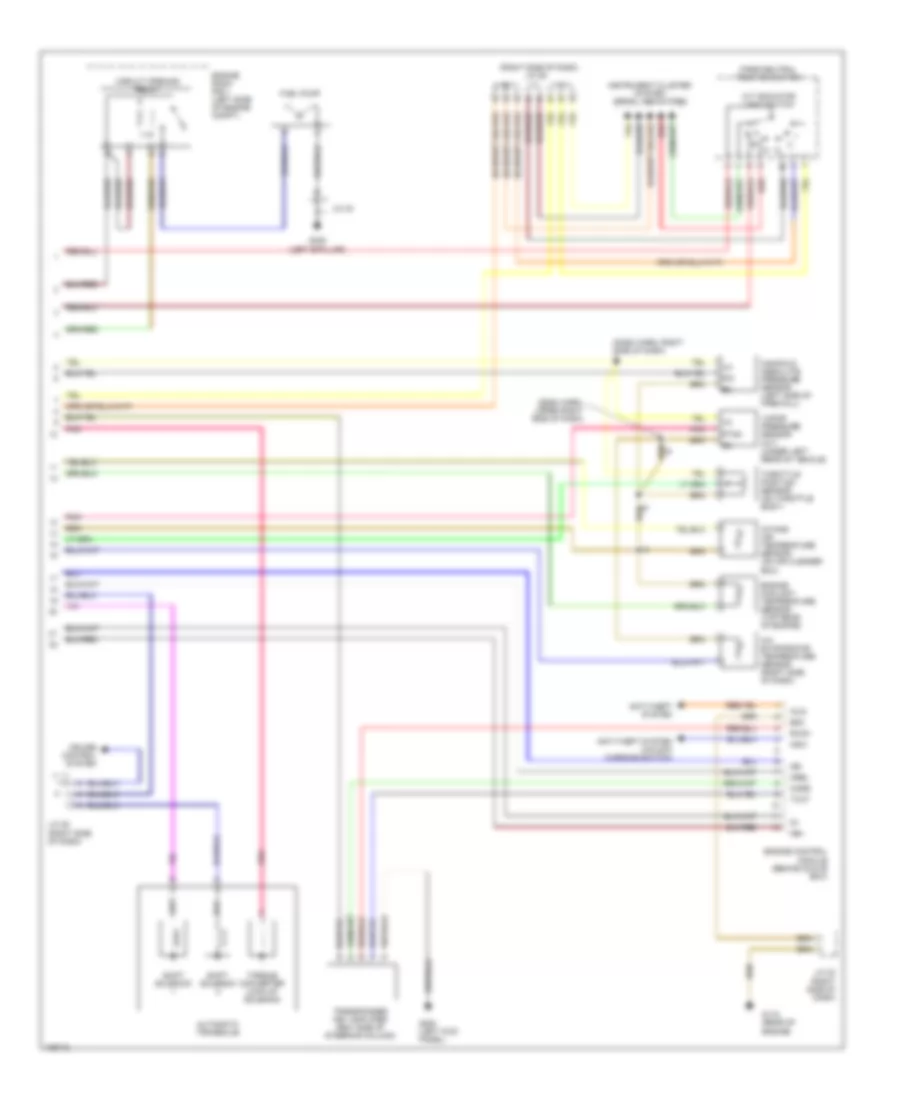
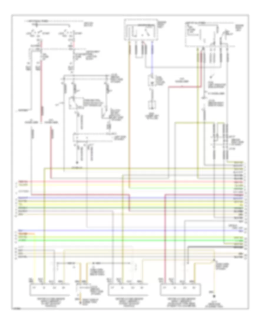
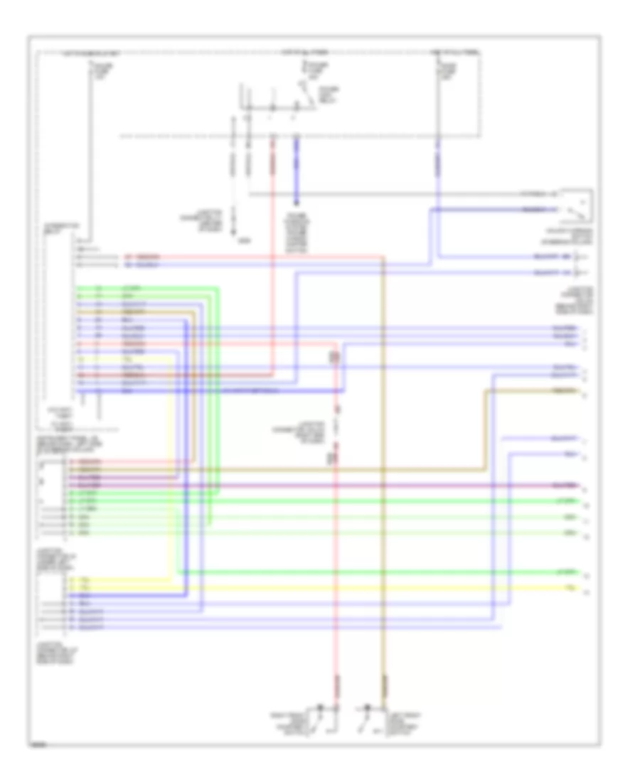
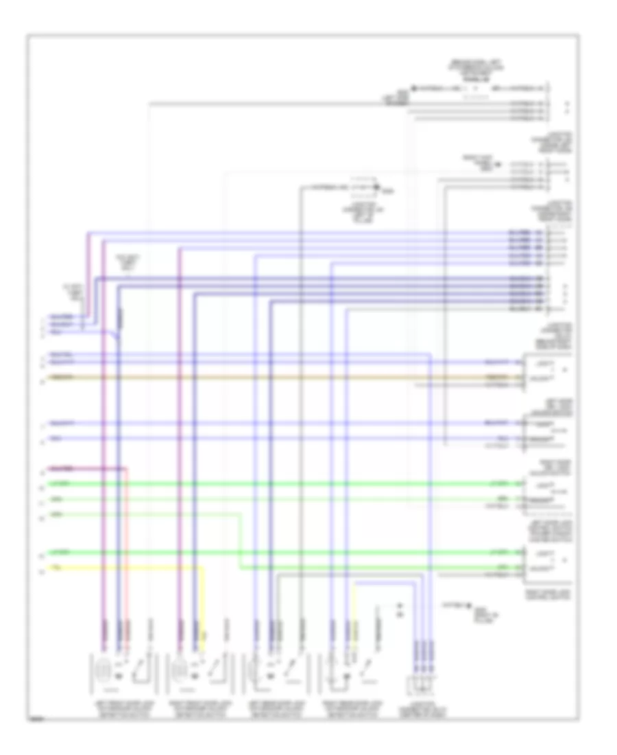
2.2L, Engine Performance Wiring Diagrams, with Immobilizer (3 of 3) for Toyota Camry CE 1998
List of elements for 2.2L, Engine Performance Wiring Diagrams, with Immobilizer (3 of 3) for Toyota Camry CE 1998:
- (dash harn, right side of dash) i2
- (dash harn, upper right side of dash)
- (right side of dash) j/c 29
- A/c evaporator temperature sensor (right side of dash)
- A/t indicator light switch
- Anti-theft system
- Anti-theft system (unlock warning switch)
- Automatic transaxle
- Circuit opening relay
- Code
- Cruise control system
- E0m
- Engine control module (behind glove box)
- Engine coolant temperature sensor (top rear of engine)
- Engine room r/b 1 (left side of engine compt)
- Fuel pump
- G115 (rear of engine)
- G200 (left kick panel)
- G308 (left b-pillar)
- Imld
- Instrument cluster system (prndl indicators)
- Intake air temperature sensor (on air cleaner box)
- J/c 23 (right side of dash)
- J/c 25 (right side of dash)
- J/c 40
- Ksw
- Manifold absolute pressure sensor (left side of firewall)
- Mrel
- Ne+
- Ne-
- Park/neutral position switch
- Pim
- Pnk
- Ptnk
- Red
- Rxck
- Shift solenoid
- Throttle position sensor (on throttle body)
- Torque converter lock-up solenoid
- Transponder key amplifier (rigt side of steering column)
- Txct
- Vapor pressure sensor (a/t) (under left rear of vehicle)
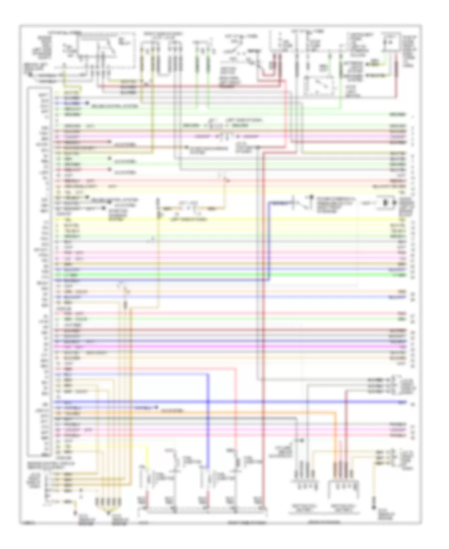
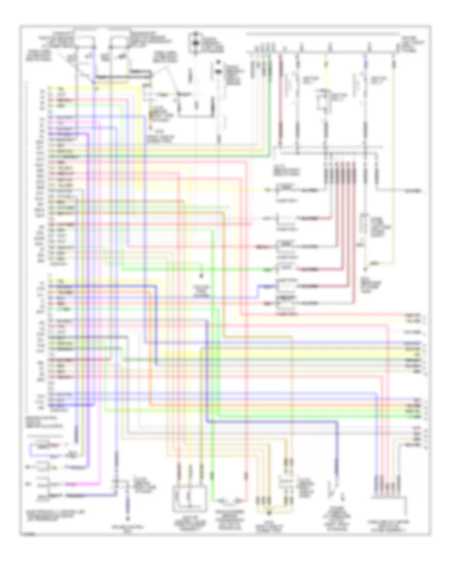
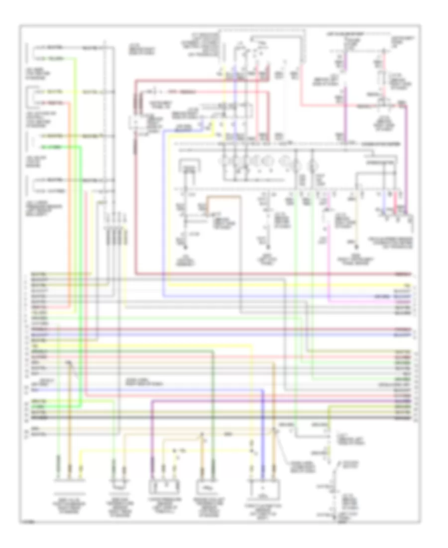
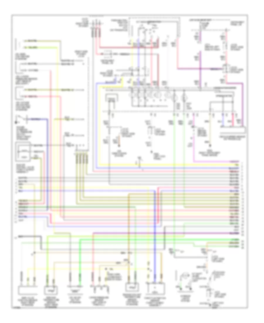
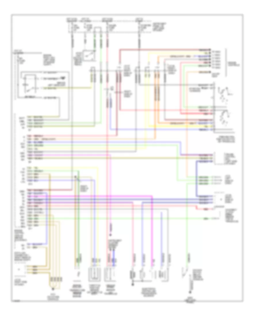
2.2L, Engine Performance Wiring Diagrams, without Immobilizer (1 of 3) for Toyota Camry CE 1998
List of elements for 2.2L, Engine Performance Wiring Diagrams, without Immobilizer (1 of 3) for Toyota Camry CE 1998:
- (a/t)
- (behind left headlamp) g106
- (calif)
- (eng harn, left front fender)
- (exc calif)
- (left side of dash)
- (rear of engine)
- (right side of dash)
- (right side of dash) j/c 27, j/c 28
- A j27
- A/c sw
- A/c system
- Acc
- Af+/ox1
- Af-
- Am2
- B j27
- Batt
- C j28
- C10
- Conn e7
- Conn e8
- Conn e9
- Cruise control system
- Defogger system
- E01
- E02
- E03
- E04
- Efi fuse 15a
- Efi relay
- Egr
- Els
- Engine control module (behind glove box)
- Engine room r/b 2 (left side of engine compt)
- Evp
- Exterior lights system
- Fuel injector
- G115 (rear of engine)
- Gnd
- Hot at all times
- Ht1
- Ht2
- Htaf
- I2 (i/p harn, behind glove blox)
- Idle-up diode (right side of dash taped to harn)
- Idlo
- Ig2
- Igf
- Ign fuse 5a
- Ignition coil/ igniter 1
- Ignition coil/ igniter 2
- Ignition switch
- Igt
- Igt1
- Igt2
- Instrument panel j/b (left of steering column)
- Iscc
- Isco
- J/c 1
- J/c 15 (top center of dash)
- J/c 19 (right side of dash)
- J/c 21
- J/c 23 (right side of dash)
- J/c 25 (right side of dash)
- J/c 7, j/c 8
- Knk
- Knock sensor (left of engine block)
- Lock
- Lock in
- Mgc
- Ne+
- Ne-
- Nsw
- Od1
- Od2
- Ox2
- Pim
- Pnk
- Power steering oil pressure switch (right front of engine)
- Prs
- Ps sw
- Ptnk
- Red
- Sil
- Spd
- Sta
- Start
- Starting/ charging system
- Starting/charging system
- Stop fuse 15a
- Stop light switch
- Stp
- Tach
- Te1
- Tha
- Thr
- Thw
- Tpc
- Vta
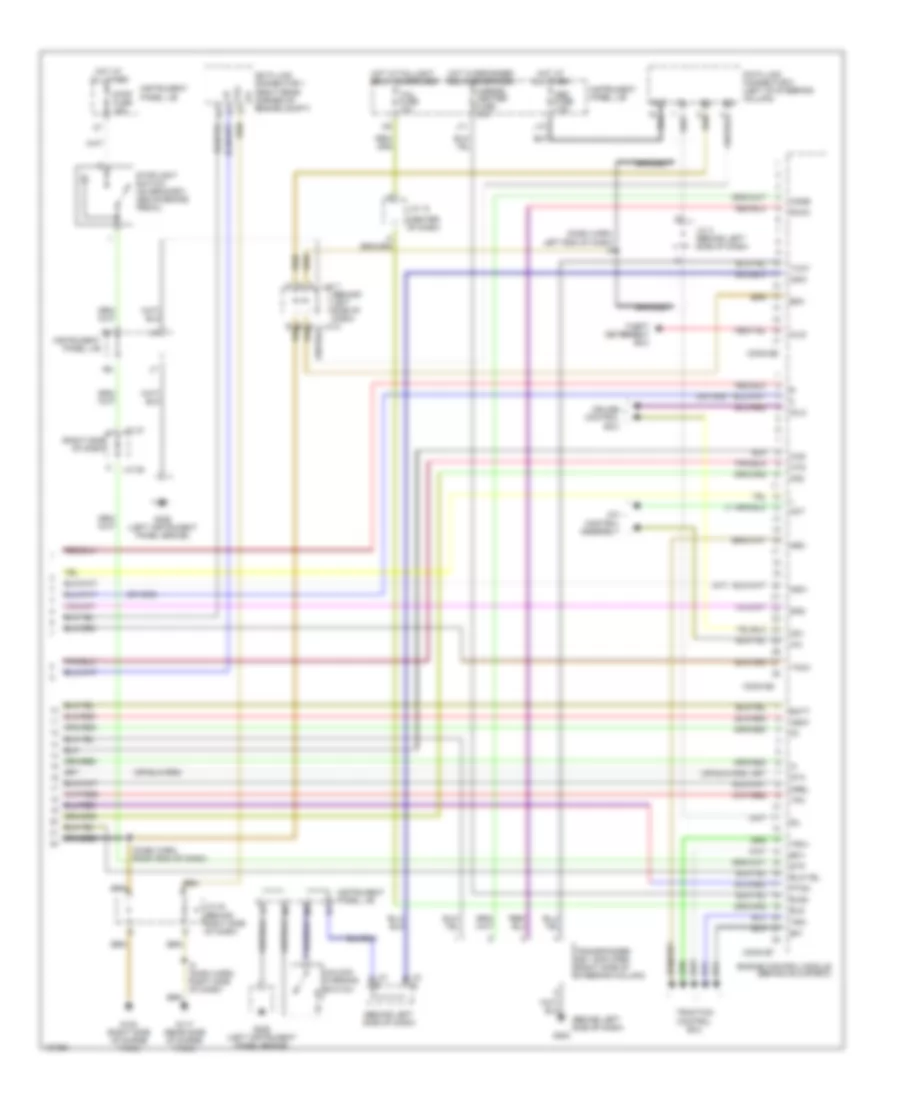
2.2L, Engine Performance Wiring Diagrams, without Immobilizer (2 of 3) for Toyota Camry CE 1998
List of elements for 2.2L, Engine Performance Wiring Diagrams, without Immobilizer (2 of 3) for Toyota Camry CE 1998:
- (left kick panel)
- (left side of engine compt)
- (right side of dash) j/c 27, j/c 28
- A/t shift lever illumination lamp
- Af+
- Af-
- Air fuel ratio sensor (calif)
- C j27
- C10
- Calif
- Camshaft position sensor (right front of engine)
- Crankshaft position sensor (right front of engine)
- Data link connector 1 (partial) (right rear corner of engine compt)
- Data link connector 3 (partial) (left of steering column)
- Egr vacuum solenoid valve (upper right front of engine)
- Evap vacuum solenoid valve (a/t) (left side of engine compt)
- Exc calif
- F j28
- G115 (rear of engine)
- G200
- G302 (below center console)
- Gauge fuse 10a
- Heated oxygen sensor (bank 1 sensor 1) (exc calif) (right side of eng)
- Heated oxygen sensor bank 1 sensor 2 (all) (rear of twc conv)
- Hot in on or start
- Idle air control valve (on throttle body)
- Instrument cluster
- Instrument cluster system (r-prndl indicator)
- Instrument panel j/b (left of steering column)
- Interior lights system
- J/c 19 (right side of dash)
- J/c 23 (left side of dash)
- J/c 5 (left side of dash)
- J/c 6 (left side of dash)
- Malfunction indicator lamp
- O/d main switch
- O/d off indicator
- Pnk
- Speedometer
- Tachometer
- Vapor pressure sensor vsv (a/t)
2.2L, Engine Performance Wiring Diagrams, without Immobilizer (3 of 3) for Toyota Camry CE 1998
List of elements for 2.2L, Engine Performance Wiring Diagrams, without Immobilizer (3 of 3) for Toyota Camry CE 1998:
- (i/p harn, right side of dash) i2
- (i/p harn, upper right side of dash)
- (in fuel tank) fuel pump/sender assembly
- (right side of dash) j/c 29
- A/c evaporator temperature sensor (right side of dash)
- A/t indicator light switch
- Automatic transaxle
- Circuit opening relay
- Cruise control system
- Engine coolant temperature sensor (top rear of engine)
- Engine room r/b 1 (left side of engine compt)
- Fuel pump
- Fuel sender
- G308 (left b-pillar)
- Instrument cluster system (low fuel ind & fuel level gauge)
- Instrument cluster system (prndl indicators)
- Intake air temperature sensor (on air cleaner box)
- J/c 25 (right side of dash)
- J/c 40
- Manifold absolute pressure sensor (left side of firewall)
- Park/neutral position switch
- Pim
- Pnk
- Ptnk
- Red
- Shift solenoid
- Throttle position sensor (on throttle body)
- Torque converter lock-up solenoid
- Vapor pressure sensor (a/t) (under left rear of vehicle)
3.0L
3.0L, Engine Performance Wiring Diagrams, California (1 of 4) for Toyota Camry CE 1998
List of elements for 3.0L, Engine Performance Wiring Diagrams, California (1 of 4) for Toyota Camry CE 1998:
- (dash harn, lower right end of dash)
- (right side of surge tank)
- Acis
- Adj2
- Afl+
- Afl-
- Afr+
- Afr-
- Camshaft position sensor (left side of of cylinder head)
- Conn e10
- Conn e11
- Cooling fans system
- Crankshaft position sensor (behind crank- shaft pulley)
- Cruise control ecu
- E01
- E02
- E03
- E04
- E05
- E2g
- Egls
- Egr
- Electronically controlled transmission solenoid (on transaxle)
- Engine control module (behind glove box)
- Evp
- G120
- G120 (rear side of surge tank)
- G120 (right side of surge tank)
- G22+
- Grd
- Hafl
- Hafr
- Idle air control valve (on throttle body)
- Igc1
- Igc2
- Igc3
- Igf
- Igniter (left front strut tower)
- Ignition coil 1
- Ignition coil 2
- Ignition coil 3
- Igt1
- Igt2
- Igt3
- Injector 1
- Injector 2
- Injector 3
- Injector 4
- Injector 5
- Injector 6
- J/c 18 (behind right side of dash)
- J/c 24 (behind right side of dash)
- J/c 26 (behind right side of dash)
- Knkl
- Knkr
- Knock sensor 1 (left side of engine)
- Knock sensor 2 (right side of engine)
- Mass airflow meter (part of air intake assembly)
- Nc2+
- Nc2-
- Nca
- Ne+
- Ne-
- Noise filter (left side of eng compt)
- Pnk
- Power steering oil pressure switch (right front of engine)
- Red
- Rsc
- Rso
- Sln+
- Sln-
- Tha
- Thg
- Thw
- Vehicle speed sensor (transmission) (on top of transaxle)
- Vta1
3.0L, Engine Performance Wiring Diagrams, California (2 of 4) for Toyota Camry CE 1998
List of elements for 3.0L, Engine Performance Wiring Diagrams, California (2 of 4) for Toyota Camry CE 1998:
- (behind right side of dash)
- (dash harn, lower right side end of dash)
- (left side of dash)
- (or
- (right side of surge tank) g120
- (under left center pillar)
- A/f htr fuse 25a
- A/f htr relay
- A/t
- Acc
- Air fuel ratio sensor (bank 1 sensor 1) (on right side of engine, in exhaust pipe)
- Air fuel ratio sensor (bank 2 sensor 1) (on left side of engine, in exhaust pipe)
- Am2
- B j/c 28
- C10
- Cir opn relay
- Clutch start switch (left side of dash)
- Efi fuse 15a
- Efi relay
- Engine room j/b 2
- Engine room relay block 1
- Engine room relay block 2
- Fuel pump (in fuel tank)
- G108 (left radiator side support)
- G117 (rear side of surge tank)
- G308
- Heated oxygen sensor (bank 1 sensor 2) (on exhaust pipe, rear of rear twc converter)
- Hot at all times
- Ig2
- Ign fuse 5a
- Ignition switch
- Instrument panel j/b
- J/c 22 (behind right side of dash)
- J/c 25 (behind right side of dash)
- J/c 29 (behind right side of dash)
- J/c 36
- J/c 7
- J/c 8
- Lock
- M/t
- Nca
- P/n
- Park/neutral position switch (on transaxle)
- Red
- St relay
- St2
- Start
- Starter fuse 5a
- W/ immobiliser
- W/o immobiliser
3.0L, Engine Performance Wiring Diagrams, California (3 of 4) for Toyota Camry CE 1998
List of elements for 3.0L, Engine Performance Wiring Diagrams, California (3 of 4) for Toyota Camry CE 1998:
- (behind right side of dash)
- (dash harn, lower right end of dash)
- (left kick panel) g200
- A/c control assembly
- A/t indicator light switch (integral to park/ neutral position switch) (on transaxle)
- Braided
- C10
- Combination meter
- Egr gas temperature sensor (right rear of engine)
- Egr valve position sensor (right rear of engine)
- Engine coolant temperature sensor (top front of engine)
- G200 (left kick panel)
- G206 (right instrument panel brace)
- Gauge fuse 10a
- H10
- Hot in on or start
- Ig+
- Instrument panel j/b
- J/c 15 (right side of dash)
- J/c 20 (behind right side of dash)
- J/c 24 (behind right side of dash)
- J/c 27
- J/c 28
- J/c 28 a
- J/c 29 (behind right side of dash)
- J/c 4 (behind left side of dash)
- J/c 5 (behind left side of dash)
- J/c 5 (left side of dash)
- J/c 6 (behind left side of dash)
- Malf ind lamp
- O/d main switch
- O/d off ind
- Pnk
- Ptnk
- Red
- Speedometer
- Tacho- meter
- Throttle position sensor (on throttle body)
- Vapor pressure sensor (left side of firewall)
- Vehicle speed sensor (combination meter) (on transaxle)
- Vss
- Vsv (egr) (top center of engine)
- Vsv (evap) (top of engine)
- Vsv (intake air control) (top center of engine)
- Vsv (vapor pressure sensor) (left rear of eng compt)
3.0L, Engine Performance Wiring Diagrams, California (4 of 4) for Toyota Camry CE 1998
List of elements for 3.0L, Engine Performance Wiring Diagrams, California (4 of 4) for Toyota Camry CE 1998:
- (a/t)
- (behind left side of dash)
- (center of dash)
- (dash harn, left end of dash) i5
- (dash harn, right end of dash)
- (right side of dash)
- A/c
- A/c control assembly
- Act
- Bat
- Batt
- Braided
- Code
- Conn e7
- Conn e8
- Conn e9
- Cruise control ecu
- Data link connector 1 (right rear corner of eng compt)
- Data link connector 3 (left of steering column)
- E0m
- Efi+
- Efi-
- Els
- Els2
- Engine control module (behind glove box)
- G117 (rear side of surge tank)
- G120 (right side of surge tank)
- G202
- G206 (left instrument panel brace)
- Hot at all times
- Hot at all times
- Hot w/defogger relay energized
- Hot w/taillight relay energized
- Hts
- Idlo
- Igsw
- Imld
- Instrument panel j/b
- J/c 10
- J/c 12
- J/c 22 (behind right side of dash)
- J/c 26 (behind right side of dash)
- J/c 27
- J/c 28
- J/c 3 (behind left side of dash)
- J/c 7
- J/c 9
- J10
- J11
- Ksw
- Mirror- heater fuse 10a
- Mrel
- Neo
- Nsw
- Obd fuse 7.5a
- Od1
- Od2
- Oxs
- Ptnk
- Rxck
- Sil
- Spd
- Sta
- Stop fuse 15a
- Stoplight switch (on bracket, above brake pedal)
- Stp
- Tach
- Tail fuse 10a
- Te1
- Theft deterrent ecu
- Tpc
- Traction control ecu
- Transponder key amplifier (right side of steering column)
- Trc+
- Trc-
- Txct
- Unlock warning switch
3.0L, Engine Performance Wiring Diagrams, Except California, with Immobilizer And/Or Traction Contr (1 of 4) for Toyota Camry CE 1998
List of elements for 3.0L, Engine Performance Wiring Diagrams, Except California, with Immobilizer And/Or Traction Contr (1 of 4) for Toyota Camry CE 1998:
- (a/t)
- (dash harn, lower right end of dash)
- (right side of surge tank)
- Acis
- Adj2
- Camshaft position sensor (left side of cylinder head)
- Conn e10
- Conn e11
- Cooling fans system
- Crankshaft position sensor (behind crankshaft pulley)
- Cruise control ecu
- E01
- E02
- E03
- E2g
- Egls
- Egr
- Electronically controlled transmission solenoid (on transaxle)
- Engine control module (behind glove box)
- Evp
- G120
- G120 (rear side of surge tank)
- G120 (right side of surge tank)
- G22+
- Grd
- Htl
- Htr
- Idle air control valve (throttle body assembly)
- Igc1
- Igc2
- Igc3
- Igf
- Igniter (left front strut tower)
- Ignition coil 1
- Ignition coil 2
- Ignition coil 3
- Igt1
- Igt2
- Igt3
- Injector 1
- Injector 2
- Injector 3
- Injector 4
- Injector 5
- Injector 6
- J/c 18 (behind right side of dash)
- J/c 22 (behind right side of dash)
- J/c 26 (behind right side of dash)
- Knkl
- Knkr
- Knock sensor 1 (left side of engine)
- Knock sensor 2 (right side of engine)
- Mass airflow meter (par of air intake assembly)
- Nc2+
- Nc2-
- Nca
- Ne+
- Ne-
- Noise filter (left side of eng compt)
- Oxl
- Oxr
- Pnk
- Power steering oil pressure switch (right front of engine)
- Red
- Rsc
- Rso
- Sln+
- Sln-
- Tha
- Thg
- Thw
- Vehicle speed sensor (transmission) (on top of transaxle)
- Vta1
3.0L, Engine Performance Wiring Diagrams, Except California, with Immobilizer And/Or Traction Contr (2 of 4) for Toyota Camry CE 1998
List of elements for 3.0L, Engine Performance Wiring Diagrams, Except California, with Immobilizer And/Or Traction Contr (2 of 4) for Toyota Camry CE 1998:
- (behind right side of dash)
- (dash harn, lower right end of dash)
- (left side of dash)
- (right side of surge tank) g120
- (under left "b" pillar)
- A/t
- Acc
- Am2
- B j/c 28
- C10
- Cir opn relay
- Clutch start switch (left side of dash)
- Efi fuse 15a
- Efi relay
- Engine room j/b 2
- Engine room r/b 1
- Fuel pump (in fuel tank)
- G108 (left radiator side support)
- G117 (rear side of surge tank)
- G308
- Heated oxygen sensor (bank 1 sensor 1) (in right exhaust manifold)
- Heated oxygen sensor (bank 1 sensor 2) (on exhaust pipe, rear of rear twc converter)
- Heated oxygen sensor (bank 2 sensor 1) (in left exhaust manifold)
- Hot at all times
- I5 (dash harn, right side of dash)
- Ig2
- Ign fuse 5a
- Ignition switch
- Instrument panel junction block
- J/c 24 (behind right side of dash)
- J/c 29 (behind right side of dash)
- J/c 35 (behind right side of dash)
- J/c 7
- J/c 8
- Lock
- M/t
- Nca
- P/n
- Park/neutral position switch (on transaxle)
- Red
- St relay
- St2
- Start
- Starter fuse 5a
- W/ immobiliser
- W/o immobiliser
3.0L, Engine Performance Wiring Diagrams, Except California, with Immobilizer And/Or Traction Contr (3 of 4) for Toyota Camry CE 1998
List of elements for 3.0L, Engine Performance Wiring Diagrams, Except California, with Immobilizer And/Or Traction Contr (3 of 4) for Toyota Camry CE 1998:
- (behind right side of dash)
- (dash harn, lower right end of dash)
- (dash harn, right end of dash)
- (left kick panel) g200
- A/c control assembly
- A/t indicator light switch (integral to park/ neutral position switch) (on transaxle)
- Braided
- C10
- Combination meter
- Egr gas temperature sensor (right rear of engine)
- Egr valve position sensor (right rear of engine)
- Engine coolant temperature sensor (top front of engine)
- G200 (left kick panel)
- G206 (right instrument panel brace)
- Gauge fuse 10a
- H10
- Hot in on or start
- Ig+
- Instrument panel j/b
- J/c 15 (behind right side of dash)
- J/c 16 (behind center of dash)
- J/c 20 (behind right side of dash)
- J/c 24 (behind right side of dash)
- J/c 27
- J/c 28
- J/c 29 (behind right side of dash)
- J/c 29 c
- J/c 4 (behind left side of dash)
- J/c 7 (behind left side of dash)
- Malf ind lamp
- O/d main switch
- O/d off ind
- Pnk
- Ptnk
- Red
- Speedometer
- Tacho- meter
- Throttle position sensor (on throttle body)
- Vapor pressure sensor (left side of firewall)
- Vehicle speed sensor (combination meter) (on transaxle)
- Vss
- Vsv (egr) (top center of engine)
- Vsv (evap) (top of engine)
- Vsv (intake air control) (top center of engine)
- Vsv (vapor pressure sensor) (left rear of eng compt)
3.0L, Engine Performance Wiring Diagrams, Except California, with Immobilizer And/Or Traction Contr (4 of 4) for Toyota Camry CE 1998
List of elements for 3.0L, Engine Performance Wiring Diagrams, Except California, with Immobilizer And/Or Traction Contr (4 of 4) for Toyota Camry CE 1998:
- (a/t)
- (behind left side of dash)
- (behind right side of dash)
- (center of dash)
- (dash harn, left end of dash) i5
- (dash harn, right end of dash)
- (right side of dash)
- A/c
- A/c control assembly
- Act
- Bat
- Batt
- Braided
- Code
- Conn e7
- Conn e8
- Conn e9
- Cruise control ecu
- Data link connector 1 (right rear corner of engine compt)
- Data link connector 3 (left of steering column)
- E0m
- Efi+
- Efi-
- Els
- Els2
- Engine control module (behind glove box)
- G117 (rear side of surge tank)
- G120 (right side of surge tank)
- G202
- G206 (left instrument panel brace)
- Hot at all times
- Hot at all times
- Hot w/defogger relay energized
- Hot w/taillight relay energized
- Hts
- I5 (dash harn, right side of dash)
- Idlo
- Igsw
- Imld
- Instrument panel j/b
- J/c 12
- J/c 24
- J/c 27
- J/c 28
- J/c 3 (behind left side of dash)
- J/c 7
- J/c b
- J10
- J11
- Ksw
- Mirror- heater fuse 10a
- Mrel
- Neo
- Nsw
- Obd fuse 7.5a
- Od1
- Od2
- Oxs
- Ptnk
- Rxck
- Sil
- Spd
- Sta
- Stop fuse 15a
- Stoplight switch (on bracket, above brake pedal)
- Stp
- Tach
- Tail fuse 10a
- Te1
- Theft deterrent ecu
- Tpc
- Traction control ecu
- Transponder key amplifier (right side of steering column)
- Trc+
- Trc-
- Txct
- Unlock warning switch
3.0L, Engine Performance Wiring Diagrams, Except California, without Immobilizer & Traction Control (1 of 3) for Toyota Camry CE 1998
List of elements for 3.0L, Engine Performance Wiring Diagrams, Except California, without Immobilizer & Traction Control (1 of 3) for Toyota Camry CE 1998:
- (behind glove box) engine control module
- (dash harn, lower right end of dash)
- (m/t)
- (right surge tank)
- (right surge tank) g120
- Acc
- Adj1
- Adj2
- Am2
- Braid
- C10
- Camshaft position sensor (left side of cylinder head)
- Circuit opening relay
- Clutch start switch (m/t)
- Conn e10
- Conn e9
- Crankshaft position sensor (behind crank- shaft pulley)
- Cruise control system (a/t)
- E01
- E02
- E03
- Efi fuse 15a
- Efi relay
- Electronically controlled transmission solenoid (on transaxle) (a/t)
- Engine room j/b 2
- Engine room r/b 1
- Fuel pump (in fuel tank)
- G108 (left radiator side support)
- G120
- G120 (rear side of surge tank)
- G22+
- Gnd
- Hot at all times
- Igc1
- Igc2
- Igc3
- Igf
- Ign fuse 5a
- Igniter (left front strut tower)
- Ignition coil 1
- Ignition coil 2
- Ignition coil 3
- Ignition switch
- Igt1
- Igt2
- Igt3
- Injector 1
- Injector 2
- Injector 3
- Injector 4
- Injector 5
- Injector 6
- Instrument panel j/b
- J/c 18 (right side of dash)
- J/c 22 (right side of dash)
- J/c 26 (right side of dash)
- J/c 29 (right side of dash)
- J/c 40 (base of left "b" pillar)
- Knkl
- Knkr
- Knock sensor 1 (left side of engine)
- Knock sensor 2 (right side of engine)
- Lock
- Nc2+
- Nc2-
- Ne+
- Ne-
- Noise filter (left side of engine compt)
- Nsw
- On ig2
- On st2
- Oxl
- Oxr
- Park/ neutral position switch (a/t)
- Pnk
- Red
- Rsc
- Rso
- Sln+
- Sln-
- Sta
- Start
- Starter fuse 5a
- Starting/ charging system (a/t)
- Tha
- Thw
- Vehicle speed sensor (a/t) (top of transaxle)
- Vta1
3.0L, Engine Performance Wiring Diagrams, Except California, without Immobilizer & Traction Control (2 of 3) for Toyota Camry CE 1998
List of elements for 3.0L, Engine Performance Wiring Diagrams, Except California, without Immobilizer & Traction Control (2 of 3) for Toyota Camry CE 1998:
- (left kick panel) g200
- (right side of dash) j/c 20
- A/t
- A/t indicator switch
- A/t shift lever illumination light
- Air conditioning system
- C10
- Combination meter
- Egr gas temperature sensor (right rear of engine)
- Egr valve position sensor (right rear of engine)
- Engine coolant temperature sensor (top front of engine)
- G200 (left kick panel)
- G302 (right instrument panel brace)
- Gauge fuse 10a
- H10
- Hot in on or start
- I2 (dash harn, lower right end of dash)
- Idle air control valve (throttle body assembly)
- Instrument panel j/b
- Interior lights system
- J/c 15 (behind center of dash)
- J/c 24 (right side of dash)
- J/c 27, j/c 28 (right side of dash)
- J/c 28 (right side of dash)
- J/c 29 (right side of dash)
- J/c 4 (behind left side of dash)
- J/c 5 (center of dash)
- J/c 5 (left side of dash)
- J/c 6 (left side of dash)
- Malf ind lamp
- O/d main switch (a/t)
- O/d off ind
- Park/neutral position switch (a/t) (on transaxle)
- Pnk
- Power steering oil pressure switch (right front of engine)
- Ptnk
- Red
- Speedometer
- Tacho- meter
- Throttle position sensor (throttle body assembly)
- Vapor pressure sensor (left side of firewall)
- Vcc
- Vehicle speed sensor (on transaxle)
- Vsv (egr) (top center of engine)
- Vsv (evap) (on top of engine)
- Vsv (intake air control) (top center of engine)
- Vsv (vapor pressure sensor) (left rear of eng compt)
3.0L, Engine Performance Wiring Diagrams, Except California, without Immobilizer & Traction Control (3 of 3) for Toyota Camry CE 1998
List of elements for 3.0L, Engine Performance Wiring Diagrams, Except California, without Immobilizer & Traction Control (3 of 3) for Toyota Camry CE 1998:
- (a/t)
- (dash harn, right end of dash)
- (right side of dash) j/c 22
- A/c
- Acis
- Act
- Air conditioning system
- Anti-lock brakes system
- Bat
- Batt
- Braid
- Conn e7
- Conn e8
- Cooling fans system
- Cruise control system
- Dash harn, left end of dash)
- Data link connector 1 (right rear corner of eng compt)
- Data link connector 3 (left of steering column)
- E2g
- Egls
- Egr
- Els
- Els2
- Engine control module (behind glove box)
- Evp
- G120 (rear side of surge tank)
- Heated oxygen sensor (bank 1 sensor 1) (on right exhaust manifold)
- Heated oxygen sensor (bank 1 sensor 2) (on exhaust pipe, rear of rear twc converter)
- Heated oxygen sensor (bank 2 sensor 1) (on left exhaust manifold)
- Hot at all times
- Hot at all times
- Hot with rear defogger on
- Htl
- Htr
- Hts
- Instrument panel j/b
- J/c 11 (left instru- ment panel brace)
- J/c 12 (center of dash)
- J/c 27, j/c 28 (right side of dash)
- J/c 3 (left side of dash)
- J/c 7, j/c 8 (left side of dash)
- J10
- J11
- Mass airflow meter (part of air intake assembly)
- Mirror- heater fuse 10a
- Neo
- Obd fuse 7.5a
- Od1
- Od2
- Odlo
- Oxs
- Pnk
- Ptnk
- Sil
- Spd
- Stop fuse 15a
- Stoplight switch (on bracket, above brake pedal)
- Stp
- Tach
- Tail fuse 10a
- Te1
- Thg
- Tpc
EXTERIOR LIGHTS
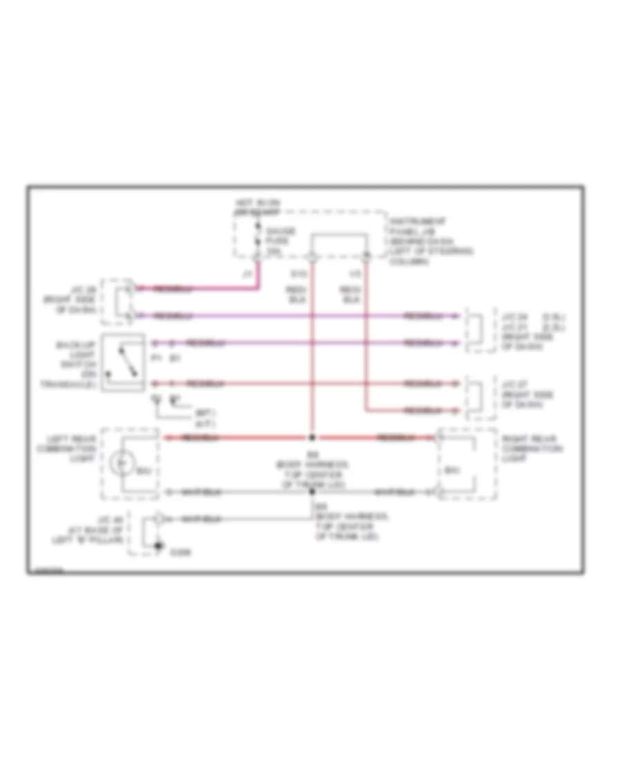
Back-up Lamps Wiring Diagram for Toyota Camry CE 1998
List of elements for Back-up Lamps Wiring Diagram for Toyota Camry CE 1998:
- (3.0l) (2.2l)
- (a/t)
- (m/t)
- B/u
- B8 (body harness, top center of trunk lid)
- B9 (body harness, top center of trunk lid)
- Back-up light switch (on transaxle)
- G308
- Gauge fuse 10a
- Hot in on or start
- Instrument panel j/b (behind dash, left of steering column)
- J/c 24 j/c 21 (right side of dash)
- J/c 27 (right side of dash)
- J/c 28 (right side of dash)
- J/c 40 (at base of left "b" pillar)
- Left rear combination light
- Right rear combination light
- S13
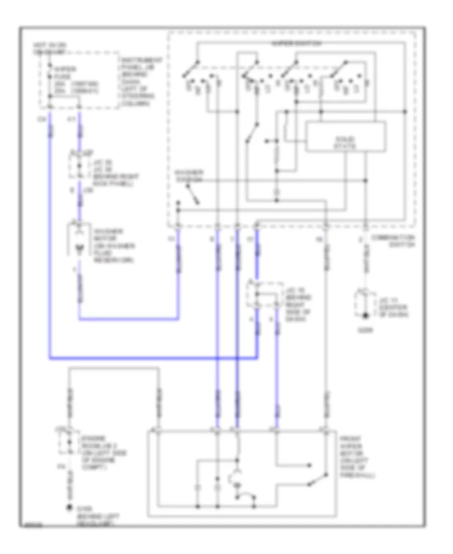
Exterior Lamps Wiring Diagram for Toyota Camry CE 1998
List of elements for Exterior Lamps Wiring Diagram for Toyota Camry CE 1998:
- (body harn,
- (body harn, above left taillight)
- (body harn, base of left "c" pillar) b5
- (body harn, center of trunk lid) b8
- (body harness, top center of trunk lid)
- (engine harn, left front fender)
- A 1999 japan made w/ drl
- Alt fuse 100a
- B 1998 & 1999 except japan made w/ drl
- B/u
- B10 top center of trunk lid)
- B11
- Back- up lamps ckt
- C 1999 usa made
- C10
- C9 c9
- Comb- ination meter
- Comb- ination switch
- Combin- ation meter
- Daytime running lamps relay (main) (behind dash, right of steering column)
- Engine room j/b (left side of engine compt)
- From j/c 12 (diagram 1 of 1)
- Fusible link block (left side of engine compt, inside j/b 2)
- G106 (behind left headlight)
- G200 (left kick panel)
- G206
- G308
- G407 (center rear of trunk)
- Gauge fuse 10a
- Hazard fuse 10a
- Hazard switch
- Head
- High mount stop light
- Hot at all times
- Hot in on or start
- I/p
- I/p j/b (behind dash, left of steering column)
- Instrument panel j/b (behind dash, left dash, left dash, left of steering of steering of steering column)
- Instrument panel j/b (behind dash, left of steering column)
- Integration relay (on instrument panel j/b)
- J/b (behind dash, left of steering column)
- J/c 11 (below top center of dash)
- J/c 12 (below top center of dash)
- J/c 15 (below top center of dash)
- J/c 2 (left kick panel)
- J/c 35, & 36 (right side of dash)
- J/c 4 (left kick panel)
- J/c 40 (base of left "b" pillar)
- J/c 5 (left side of dash)
- J/c 7 (left side of dash)
- J35
- J36
- Left front combination light
- Left rear combination light
- License plate lights
- Light ctrl switch
- Light failure sensor (left side of trunk)
- Off
- Park
- Rear light warning ind
- Red
- Right front combination light
- Right rear combination light
- S11
- Side marker
- Stop
- Stop fuse 15a
- Stop- light switch (on bracket above brake pedal)
- Tail
- Tail fuse 10a
- Tail- light relay
- To j/c 35 (diagram 1 of 1)
- Turn
- Turn fuse 7.5a
- Turn signal flasher (behind left kick panel)
- Turn signal ind
- Turn signal switch
GROUND DISTRIBUTION
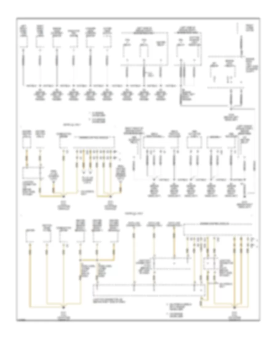
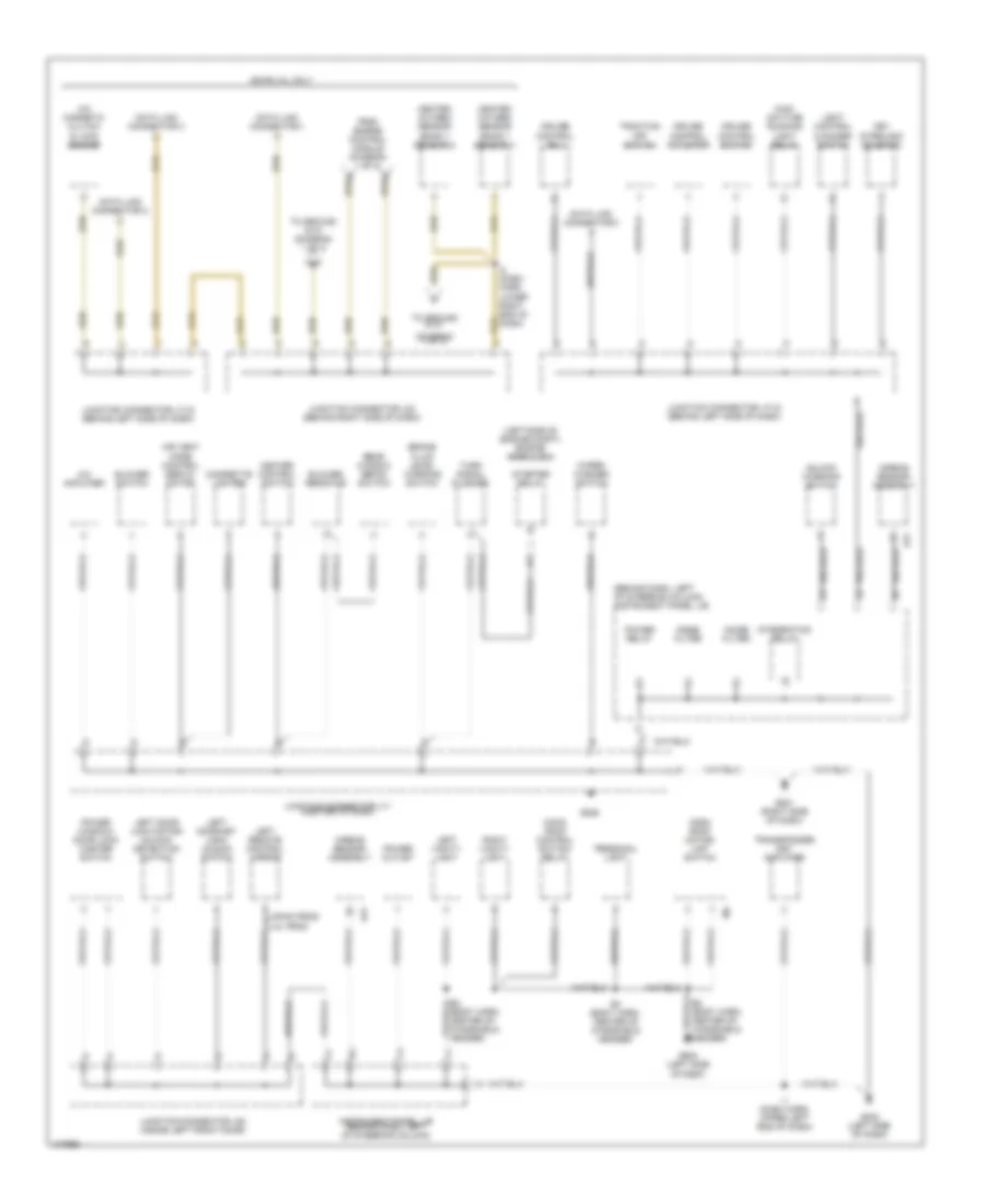
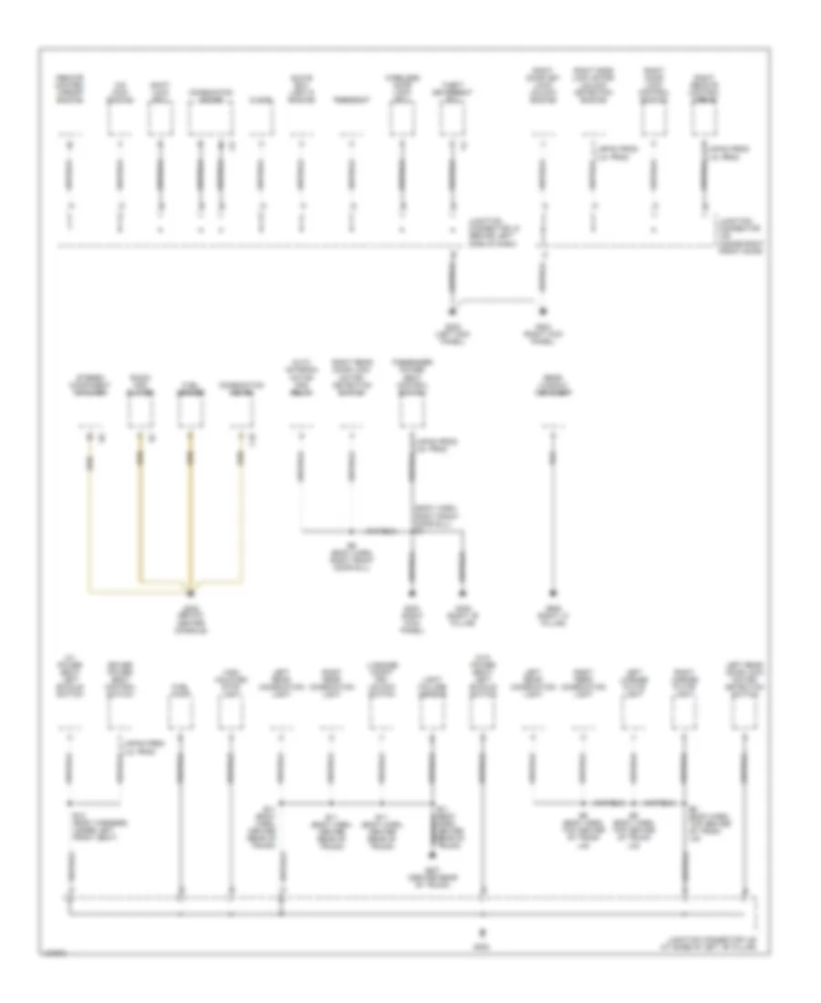
Ground Distribution Wiring Diagram (1 of 3) for Toyota Camry CE 1998
List of elements for Ground Distribution Wiring Diagram (1 of 3) for Toyota Camry CE 1998:
- (left side of engine compt) engine room r/b 1
- (left side of engine compt) engine room r/b 2
- (right front of engine compt) engine room r/b 3
- 1 (or 2)
- 1mz-fe 3.0l only
- 2.2l only
- 5s-fe 2.2l only
- A/f heater relay
- A15
- A18
- Abs & traction actuator
- Abs & traction ecu
- Abs actuator
- Abs actuator & ecu
- Abs ecu
- Abs solenoid relay
- California models or w/ engine immobilizer
- California only
- Combination meter
- Data link connector 1
- Data link connector 2
- Data link connector 3
- Daytime running light resistor
- Drl relay
- E1 (engine harn, behind right headlight)
- E10
- E11
- E4 (engine harn, left front fender)
- Efi relay
- Engine control module
- Engine hood courtesy switch
- Engine main relay
- Engine room j/b 2 (left side of engine compt)
- Fan relay
- From heated oxygen sensor (diagram 2 of 3)
- From j/c j23 (diagram 2 of 3)
- Front wiper motor
- G106 (behind left headlight)
- G107 (behind right headlight)
- G131 (2.2l) (on intake manifold)
- G131 (3.0l) (on intake manifold)
- Heated oxygen sensor (bank 1 sensor 1)
- Heated oxygen sensor (bank 1 sensor 2)
- Heated oxygen sensor (bank 2 sensor 1)
- Heater relay
- I2 (dash harn, lower right end of dash)
- Igniter
- Igniter/ ignition coil 1
- Igniter/ ignition coil 2
- Ignition noise filter
- J10
- Junction connector j19 (behind right side of dash)
- Junction connector j22 (behind right side of dash)
- Junction connector j26 (calif) (behind right side of dash)
- Junction connector j7/j8 (behind left side of dash)
- Left front park/ turn light
- Radiator fan motor
- Right front park/ turn light
- To j/c j23 (diagram 2 of 3)
- W/ engine immobilizer
- W/o engine immobilizer
- Washer level warning switch
- Water temp switch
Ground Distribution Wiring Diagram (2 of 3) for Toyota Camry CE 1998
List of elements for Ground Distribution Wiring Diagram (2 of 3) for Toyota Camry CE 1998:
- (behind dash, left of steering column) instrument panel j/b
- (diagram 1 of 3)
- (left side of engine compt) engine room j/b 2
- 5s-fe 2.2l only
- A/c amplifier
- A/c magnetic clutch & lock sensor
- A21
- Air vent mode control servo- motor
- Airbag sensor assembly
- B2 (body harn, center of windshield header)
- B3 (body harn, center of windshield header)
- Blower resistor
- Blower switch
- Brake fluid level warning switch
- Cigarette lighter
- Cruise control actuator
- Cruise control ecu
- Cruise control switch
- Data link connector 1
- Data link connector 2
- Data link connector 3
- From engine control module (diagram 1 of 3)
- G201 (right side of dash)
- G202 (left side of dash)
- G206
- G902 (left side of roof)
- Heated oxygen sensor (bank 1 sensor 1)
- Heated oxygen sensor (bank 1 sensor 2)
- Heater control switch
- I1 (dash harn, upper left end of dash)
- I2 (dash harn, lower right end of dash)
- Instrument panel j/b (behind dash, left of steering column)
- Integration relay
- Japan prod
- Junction connector j11 (center of dash)
- Junction connector j23 (behind right side of dash)
- Junction connector j38 (inside left front door)
- Junction connector j7/j8 (behind left side of dash)
- Key interlock solenoid
- Left door key lock/ unlock switch
- Left door lock motor/ unlock detection switch
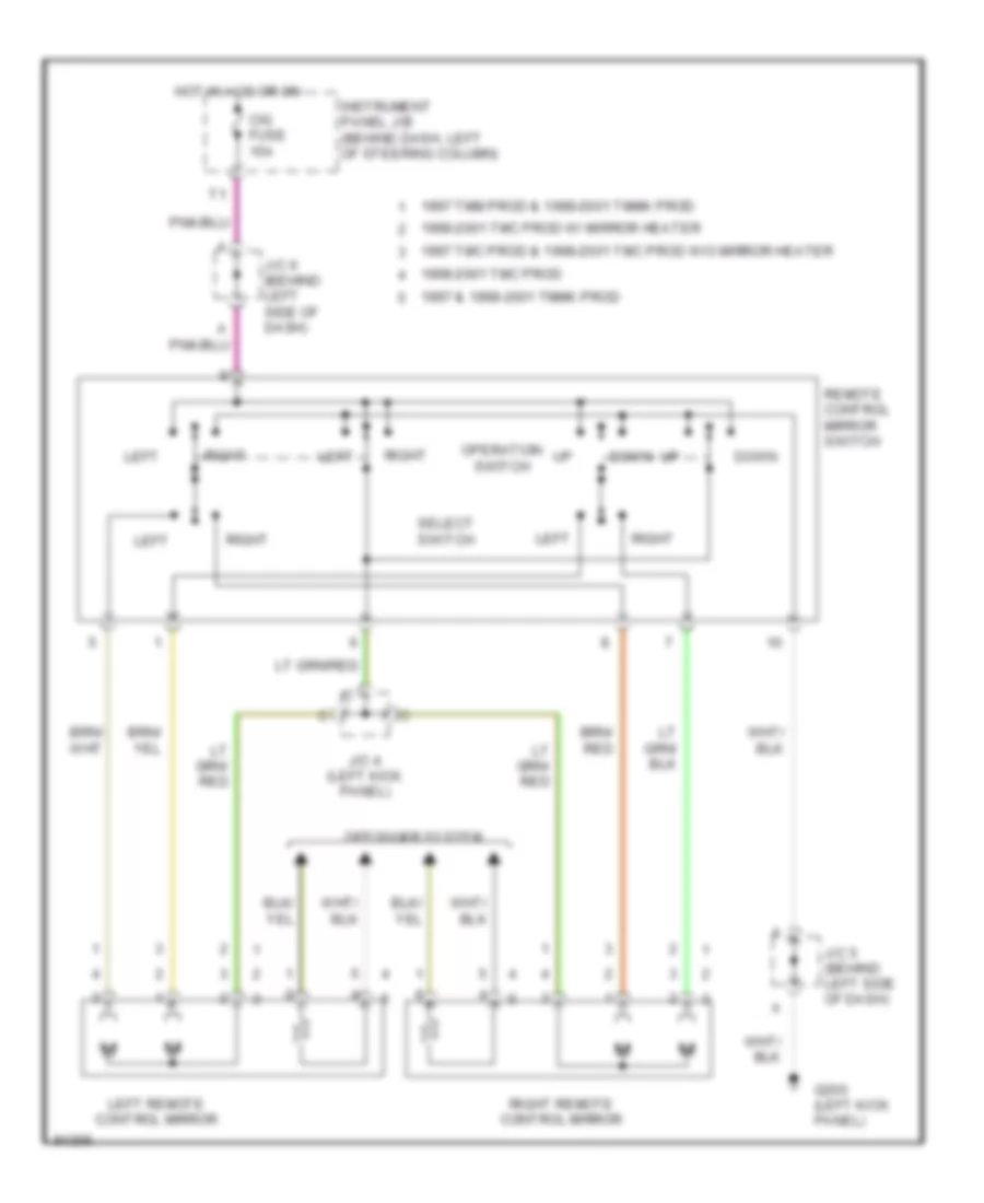
- Left remote control mirror
- Left vanity light
- Light control & dimmer switch
- Main daytime running light relay
- Moon roof control switch/ relay
- Moon roof motor/ limit switch
- Noise filter
- Personal light
- Power outlet
- Power relay
- Power window/ door lock master switch
- Rear window defog switch
- Right vanity light
- Starter relay
- To ground g131
- To ground g131 (diagram 1 of 3)
- Traction off switch
- Transponder key amplifier
- Turn signal flasher
- U.s. prod
- Unlock warning switch
- Wiper/ washer switch
Ground Distribution Wiring Diagram (3 of 3) for Toyota Camry CE 1998
List of elements for Ground Distribution Wiring Diagram (3 of 3) for Toyota Camry CE 1998:
- (body harn, right front door sill) b6
- (w/ power seat) left buckle switch
- (w/o power seat) left buckle switch
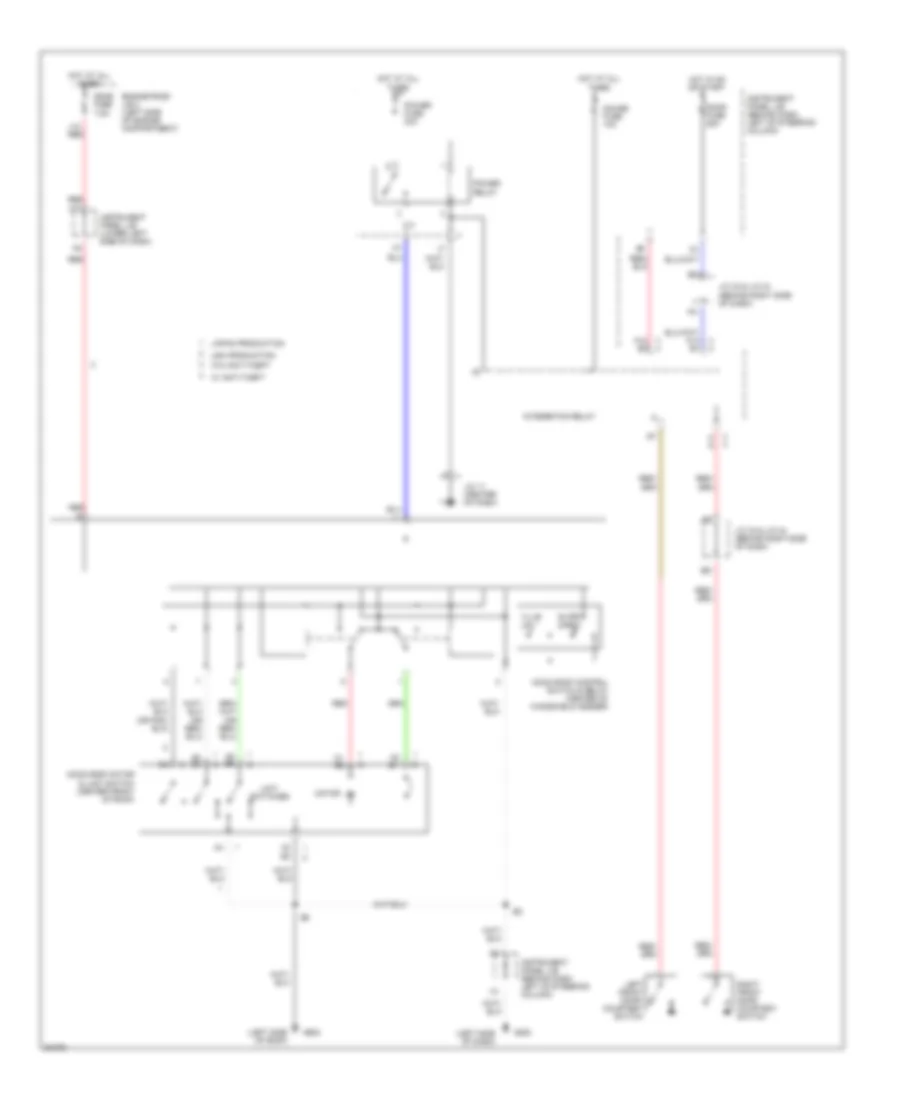
- Auto antenna motor and relay
- B11 (body harn, center rear of trunk)
- B12 (body harness, under left front seat)
- B6 (body harn, right front door sill)
- B9 (body harn, top center of trunk lid)
- C10
- Clock
- Combination meter
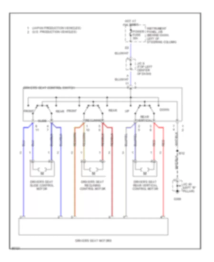
- Driver power seat control switch
- Fuel pump
- Fuel sender
- G200 (left kick panel)
- G203 (right kick panel)
- G302 (below center console)
- G305 (right "b" pillar)
- G308
- G407 (center rear of trunk)
- G905 (right "c" pillar)
- Glove box light & switch
- High mounted stop light
- Japan prod
- Junction connector j39 (inside right front door)
- Junction connector j40 (at base of left "b" pillar)
- Junction connector j5 (behind left side of dash)
- Left license plate light
- Left rear combination light
- Left rear door lock motor/ detection switch
- Light failure sensor
- Luggage compt key unlock switch
- O/d main switch
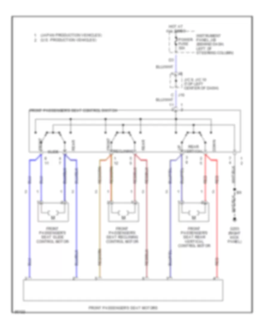
- Passenger power seat control switch
- Radio and player
- Rear window defogger
- Remote control mirror switch
- Rheostat
- Right door key lock/ unlock switch
- Right door lock control switch
- Right door lock motor/ unlock detection switch
- Right license plate light
- Right rear combination light
- Right rear door lock motor/ detection switch
- Right remote control mirror
- Shift lock ecu
- Stereo component amplifier
- Theft deterrent ecu
- U.s. prod
- Wireless door lock ecu
HEADLIGHTS
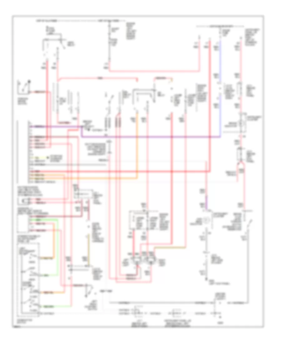
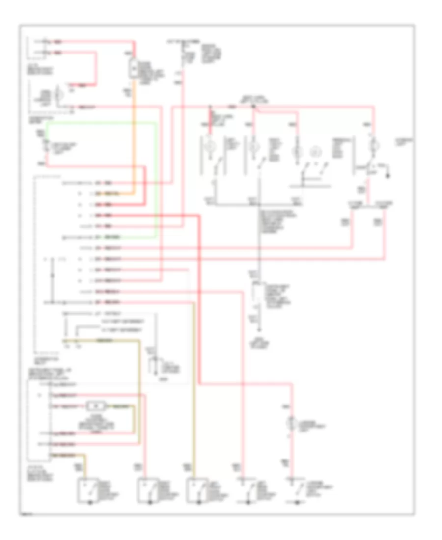
Headlight Wiring Diagram, with DRL for Toyota Camry CE 1998
List of elements for Headlight Wiring Diagram, with DRL for Toyota Camry CE 1998:
- (behind left headlight) g106
- (center of dash) j/c 11
- Brake fluid level warning switch (on brake fluid reservoir)
- Brake indicator
- C10
- Combination switch
- Daytime running light relay (main) (behind dash, right of steering column)
- Daytime running light resistor (on right rear corner of engine compt)
- Dim relay
- Dimmer switch
- Diode (drl 1) (behind left side of dash, taped to harness)
- Diode (drl 2) (behind left side of dash, taped to harness)
- Dome fuse 7.5a
- Drl 2 fuse 5a
- Drl relay no 4
- Engine room j/b 2 (on left side of engine compt)
- Engine room r/b 2 (on left side of engine compt)
- Flash
- G200 (left kick panel)
- G206
- Gauge fuse 10a
- Head
- Head relay
- High
- High beam indicator
- Hot at all times
- Hot in on or start
- I17
- Instrument cluster
- Instrument panel j/b (behind dash left of steering column)
- Instrument panel j/b (behind dash, left of steering column)
- Integration relay (on instrument panel j/b)
- J/c 1 (behind left kick panel)
- J/c 2 (behind left kick panel)
- J/c 27 j/c 28 (behind right side of dash)
- J/c 32 (behind right side of dash)
- J/c 4 (behind left kick panel)
- J/c 5 (behind left side of dash)
- J/c 7 (behind left side of dash)
- J12
- Left front courtesy switch
- Left head- light
- Light control switch
- Lower left head fuse 10a
- Lower right head fuse 10a
- Main fuse 40a
- Off
- Parking brake switch
- Red
- Right head- light
- S17
- Short pin
- Starting/ charging system
- Tail
- Upper left head fuse 15a
- Upper right head fuse 15a
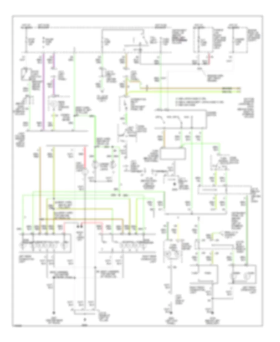
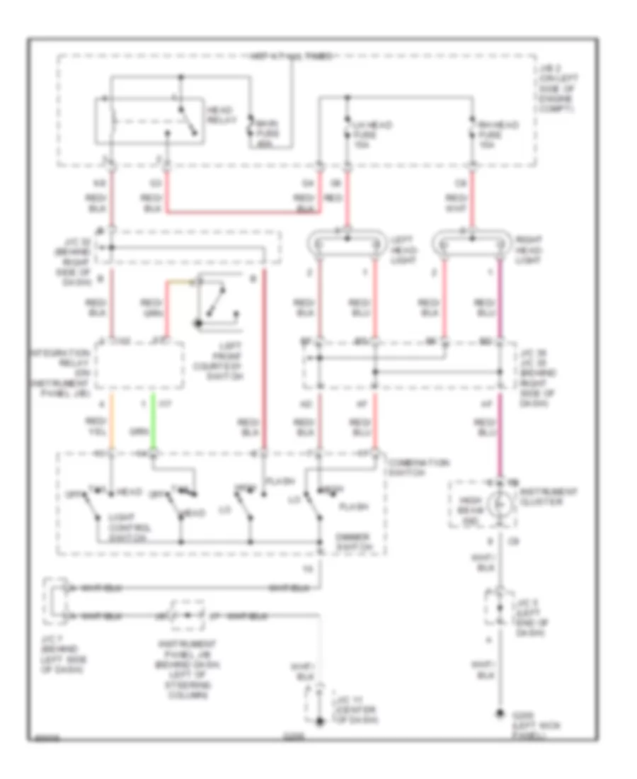
Headlight Wiring Diagram, without DRL for Toyota Camry CE 1998
List of elements for Headlight Wiring Diagram, without DRL for Toyota Camry CE 1998:
- Combination switch
- Dimmer switch
- Flash
- G200 (left kick panel)
- G206
- Head
- Head relay
- High
- High beam ind
- Hot at all times
- I17
- Instrument cluster
- Instrument panel j/b (behind dash, left of steering column)
- Integration relay (on instrument panel j/b)
- J/b 2 (on left side of engine compt)
- J/c 11 (center of dash)
- J/c 32 (behind right side of dash)
- J/c 36 j/c 35 (behind right side of dash)
- J/c 5 (left end of dash)
- J/c 7 (behind left side of dash)
- Left front courtesy switch
- Left head- light
- Lh head fuse 15a
- Light control switch
- Main fuse 40a
- Off
- Red
- Rh head fuse 15a
- Right head- light
- Tail
HORN
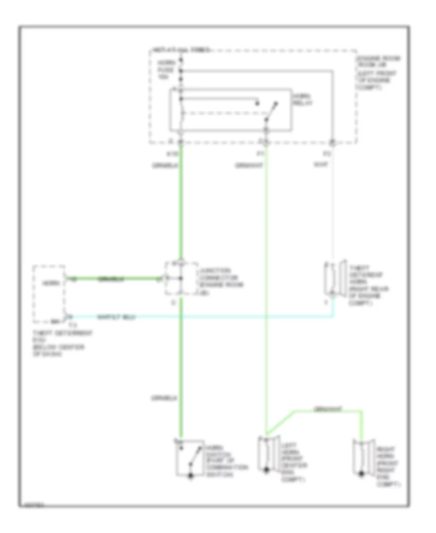
Horn Wiring Diagram for Toyota Camry CE 1998
List of elements for Horn Wiring Diagram for Toyota Camry CE 1998:
- (left front of engine compt)
- Engine room room j/b
- Horn
- Horn fuse 10a
- Horn relay
- Horn switch (part of combination switch)
- Hot at all times
- Jb)
- Junction connector (engine room
- K10
- Left horn (front center eng compt)
- Right horn (front right eng compt)
- Theft deterent horn (right rear of engine compt)
- Theft deterrent ecu (below center of dash)
INSTRUMENT CLUSTER
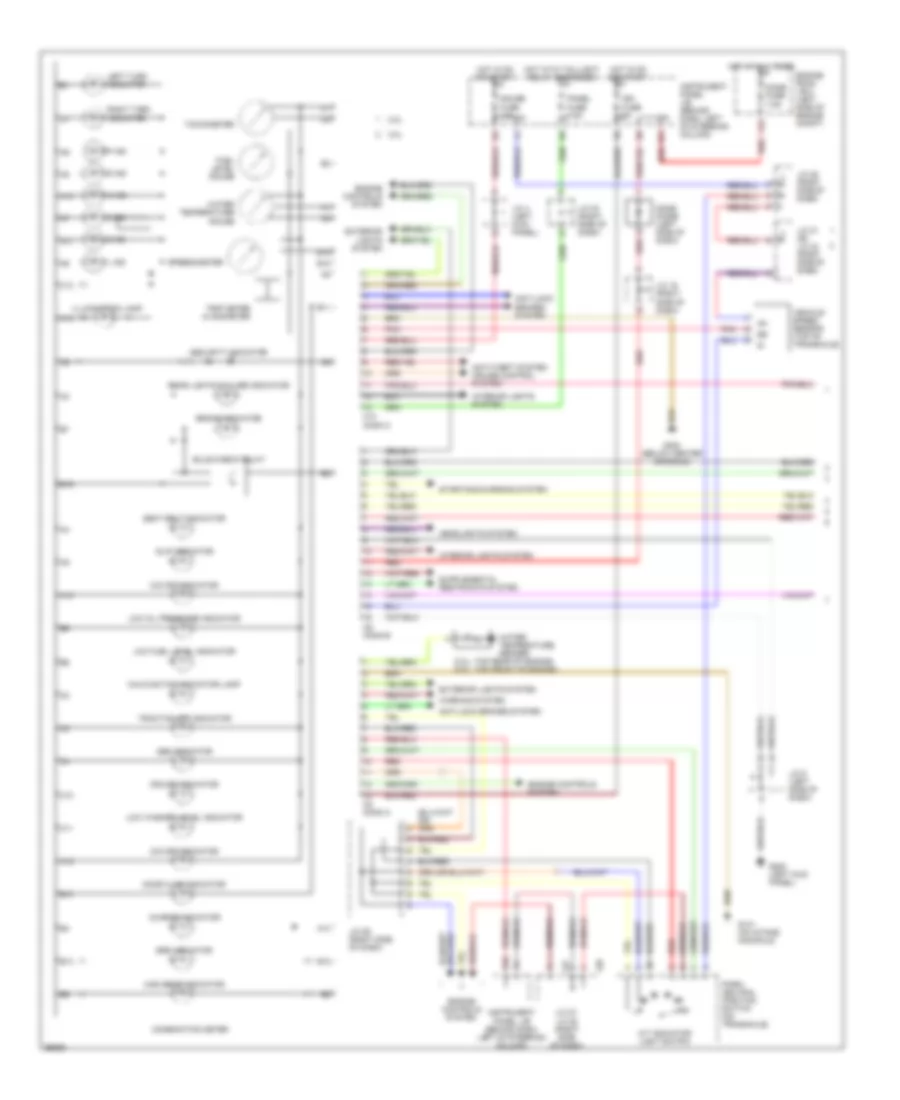
Instrument Cluster Wiring Diagram (1 of 2) for Toyota Camry CE 1998
List of elements for Instrument Cluster Wiring Diagram (1 of 2) for Toyota Camry CE 1998:
- (+)
- (-)
- (2.2l: top rear of engine) (3.0l: top front of engine)
- 2 ind
- 2.2l
- 3.0l
- A/t indicator light switch
- A10
- A11
- A12
- A13
- Abs indicator
- Anti-lock brakes system
- Anti-theft system cruise control system
- B10
- B11
- B12
- B13
- B14
- B15
- B16
- Brake indicator
- Bulb check relay
- C10
- C10 conn c
- C11
- C12
- C13
- C8 conn a
- C9 conn b
- Charge indicator
- Combination meter
- Cruise indicator
- D ind
- Dome diode (left side of dash)
- Dome fuse 7.5a
- Door ajar indicator
- Engine controls system
- Engine room j/b 2 (left side of engine compt)
- Exterior lights system
- Fuel level gauge
- G131 (on intake manifold)
- G200 (left kick panel)
- G302 (below center console)
- Gauge fuse 10a
- H10
- Headlights system
- High beam indicator
- Hot at all times
- Hot in on or start
- Hot with taillight relay energized
- Ig+
- Ign fuse 5a
- Illumination lamp
- Instrument panel j/b (behind dash, left of steering column)
- Interior lights system
- J/c 16 (right side of dash)
- J/c 21 or j/c 24 (right side of dash)
- J/c 27, j/c 28 (right side of dash)
- J/c 28 (right side of dash)
- J/c 29 (right side of dash)
- J/c 30 (right side of dash)
- J/c 4 (left kick panel)
- J/c 5 (left side of dash)
- J12
- J27
- J28
- L ind
- Left turn indicator
- Low fuel level indicator
- Low oil pressure indicator
- Low washer level indicator
- Malfunction indicator lamp
- N ind
- O/d off indicator
- P ind
- Panel fuse 7.5a
- Park/ neutral position switch (on transaxle)
- Pnk
- R ind
- Rear lights failure indicator
- Red
- Right turn indicator
- Seat belt indicator
- Security indicator
- Slip indicator
- Speedometer
- Srs indicator
- Starting/charging system
- Tachometer
- Traction off indicator
- Trip meter & odometer
- Vehicle speed sensor (top of transaxle)
- Warning system
- Water temperature gauge
- Water temperature sender
Instrument Cluster Wiring Diagram (2 of 2) for Toyota Camry CE 1998
List of elements for Instrument Cluster Wiring Diagram (2 of 2) for Toyota Camry CE 1998:
- (canada only)
- (on transaxle) park/neutral position switch
- 2.2l
- 3.0l
- A/t
- B j7
- Brake fluid level warning switch
- Brk
- Canada
- Clutch start switch
- Conn e7
- Cruise control ecu (left side of dash)
- Daytime running light main relay (canada) (right of steering column)
- Engine control module (behind glove box)
- Fuel pump/ fuel sender (in fuel tank)
- Fuel sender
- G106 (behind left headlight)
- G206
- G302 (below center console)
- Hot in start
- Instrument panel j/b (behind dash, left of steering column)
- J/c 11 (below center of dash)
- J/c 15 (top center of dash)
- J/c 2 (behind left kick panel)
- J/c 26 (right side of dash)
- J/c 29 (right side of dash)
- J/c 7, j/c 8 (below left side of dash)
- M/t
- Oil pressure switch (2.2l: left side of cyl block) (3.0l: left front of engine block)
- Parking brake switch
- Prk
- Spd
- Starter fuse 5a
- Usa
- Washer level warning switch
INTERIOR LIGHTS
Courtesy Lamps Wiring Diagram for Toyota Camry CE 1998
List of elements for Courtesy Lamps Wiring Diagram for Toyota Camry CE 1998:
- (body harn, left "a" pillar) b1
- B1 (body harn, left "a" pillar)
- B3 (w/moon roof) b2 (w/o moon roof) (body harn, center of windshield header)
- Combination meter
- Diode (courtesy) (behind right side of dash, taped to harn)
- Diode (dome) (behind left side of dash, taped to harn)
- Dome fuse 7.5a
- Door
- Engine room j/b 2 (left side of engine compt)
- G202 (left side of dash)
- G206
- H11
- Hot at all times
- I18
- Ignition key cylinder light
- Instrument panel j/b (behind dash, left of steering column)
- Integration relay
- Interior light
- J/c 11 (center of dash)
- J/c 16 (behind right side of dash)
- J/c 33 (a) & j/c 34 (b) (behind right side of dash)
- J12
- Left front door courtesy switch
- Left rear door courtesy switch
- Left vanity light
- Luggage compartment light
- Luggage compartment light switch
- Off
- Open door warning light
- Personal light (w/o moon roof)
- Red
- Right front door courtesy switch
- Right rear door courtesy switch
- Right vanity light (w/ moon roof)
- S12
- W/ fade out
- W/ theft deterrent
- W/o fade out
- W/o theft deterrent
Instrument Illumination Wiring Diagram for Toyota Camry CE 1998
List of elements for Instrument Illumination Wiring Diagram for Toyota Camry CE 1998:
- (left kick panel) g200
- A/c switch
- A/t shift lever illumination (o/d main switch)
- Ashtray illumination
- Blower switch
- C12
- C13
- Cigarette lighter illumination
- Combination meter
- G206
- Glove box light & switch
- Hazard switch
- Head
- Hot at all times
- Ill
- Instrument panel j/b (behind dash, left of steering column)
- Integration relay (part of instrument panel j/b, left side of dash)
- J/c 11 (below top center of dash)
- J/c 13 (a) & j/c 14 (b) (below top center of dash)
- J/c 16 (a) & j/c 17 (b) (behind right side of dash)
- J/c 2 (left side of dash)
- J/c 30 (a) & j/c 31 (b) (behind right side of dash)
- J/c 5 (behind left side of dash)
- J/c 7 (behind left side of dash)
- Light control switch (part of combination switch)
- Off
- Panel fuse 7.5a
- Radio & player
- Rear window defogger switch
- Rheostat
- Tail
- Taillight relay
- W/built-in type amplifier
- W/separate type amplifier
POWER ANTENNA
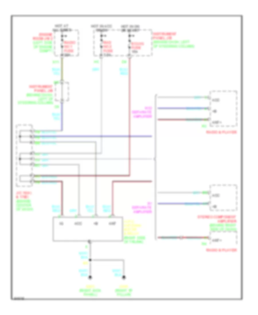
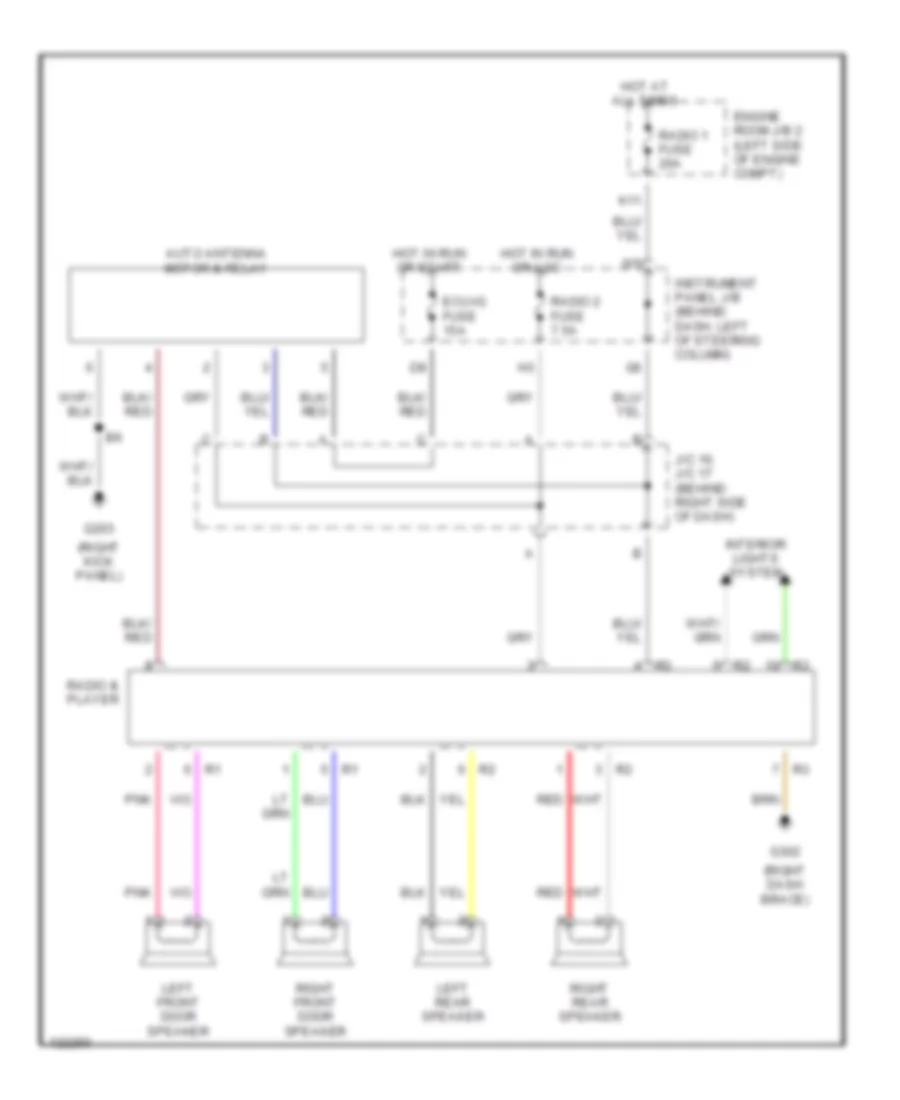
Power Antenna Wiring Diagram for Toyota Camry CE 1998
List of elements for Power Antenna Wiring Diagram for Toyota Camry CE 1998:
- Acc
- Ant
- Ant+
- Auto antenna motor & relay (right side of trunk)
- Ecu-ig fuse 15a
- Engine room j/b 2 (left side of engine compt)
- G203 (right kick panel)
- G305 (right "b" pillar)
- Hot at all times
- Hot in acc or on
- Hot in on or start
- Instrument panel j/b (behind dash, left of steering column)
- J/c 16(a) & 17(b) (behind center of dash)
- K11
- Rad no.2 fuse 7.5a
- Radio & player
- Radio no.1 fuse 20a
- Stereo component amplifier (behind right side of dash)
- W/ separate amplifier
- W/o separate amplifier
POWER DISTRIBUTION
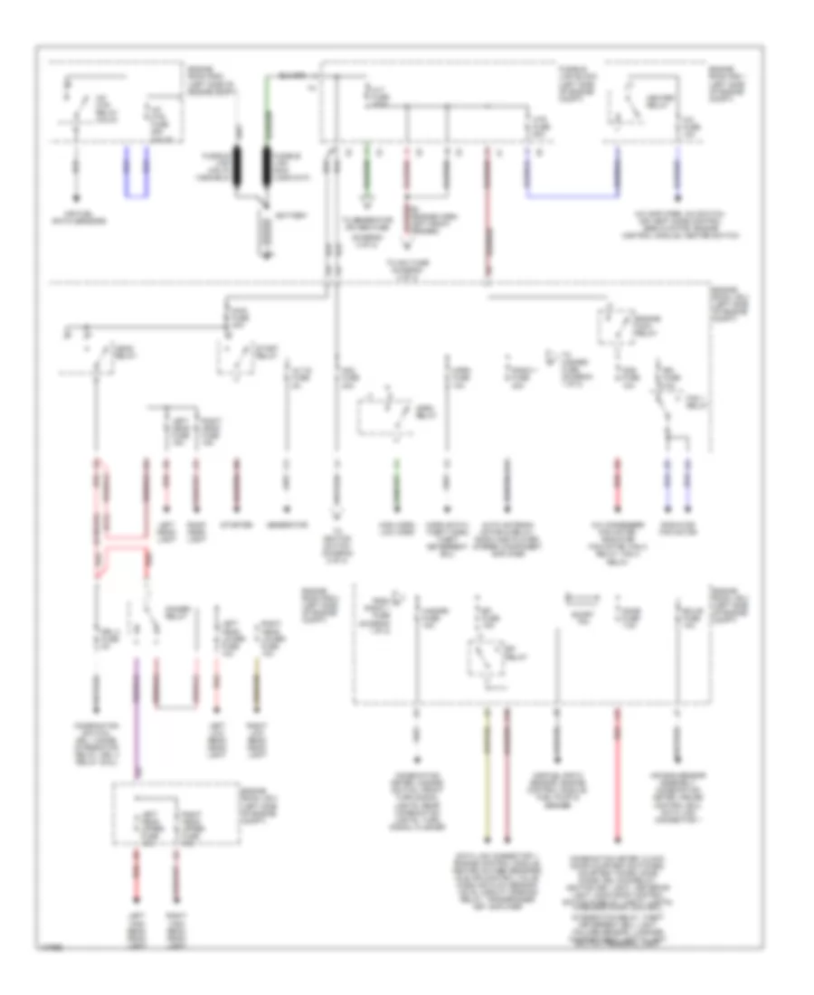
Power Distribution Wiring Diagram (1 of 2) for Toyota Camry CE 1998
List of elements for Power Distribution Wiring Diagram (1 of 2) for Toyota Camry CE 1998:
- (canada)
- (diagram 2 of 2)
- (u.s.)
- A/c amplifier, a/c switch, air vent mode control servo motor, engine control module, heater switch
- A/c condenser fan motor, radiator fan motor, fan 2 relay, fan 3 relay
- A/c fuse 10a
- A/f htr fuse 25a (calif)
- A/f htr relay (calif)
- Air bag sensor assembly, combination meter, cruise control ecu, data link connector 1
- Air fuel ratio sensors
- Air/fuel ratio sensor, engine control module, fuel pump & sender
- Alt fuse 100a
- Alt-s fuse 5a
- Am2 fuse 30a
- Auto antenna motor & relay, radio and player, stereo component amplifier
- Battery
- C10
- Cds fuse 10a
- Combination meter, clock, door courtesy switches, courtesy diode, dome diode, drl main relay, ignition key light, ineterior light, moon roof control switch & relay, vanity lights, wireless door lock ecu,
- Combination meter, hazard switch, front turn signal lights, rear combination lights, turn signal flasher
- Combination switch, drl 1 diode, integration relay, drl 4 relay (coil)
- Data link connector 1, engine control module, heated oxygen sensors, idle air control valve, mass air flow sensor, vsv's, circuit opening relay, transponder key amplifier
- Dimmer relay
- Dome fuse 7.5a
- Drl 2 fuse 5a
- E3 (engine harn, left front fender)
- Ecu-b fuse 10a
- Efi fuse 15a
- Efi relay
- Engine main relay
- Engine room j/b 2 (left side of engine compt)
- Engine room r/b 1 (left side of engine compt)
- Engine room r/b 2 (left side of engine compt)
- Engine room r/b 2 (left side of engine compt)
- Fan 1 relay
- From c radio 1 fuse (diagram 1 of 2)
- Fusible link block (left side of engine compt)
- Generator
- Hazard fuse 10a
- Head relay
- Heater relay
- High horn, low horn
- Horn fuse 10a
- Horn relay
- Horn swith, theft horn, theft deterrent ecu
- Htr fuse 50a
- Integration relay, theft deterrent ecu, light failure sensor, luggage compartment light & light switch, personal light
- J12
- K11
- Left head fuse 15a
- Left head lower fuse 10a
- Left head upper fuse 15a
- Left head- light
- Left high beam head- light
- Left low beam head- light
- Main fuse 40a
- Radiator fan motor
- Radio 1 fuse 20a
- Rdi fuse 10a
- Red
- Right head fuse 15a
- Right head lower fuse 10a
- Right head upper fuse 15a
- Right head- light
- Right high beam head- light
- Right low beam head- light
- Short pin
- Start relay
- Starter
- To am1 fuse (diagram 2 of 2)
- To generator or abs fuse
- To hazard fuse (diagram 1 of 2)
- To ignition switch (diagram 2 of 2)
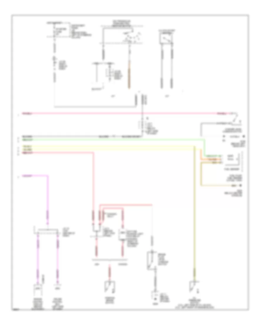
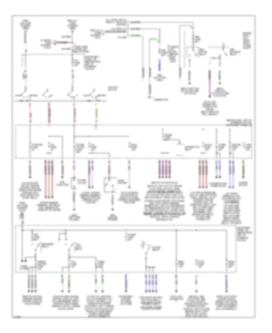
Power Distribution Wiring Diagram (2 of 2) for Toyota Camry CE 1998
List of elements for Power Distribution Wiring Diagram (2 of 2) for Toyota Camry CE 1998:
- & door unlock detect switches, ecm, fuel pump & sender, generator, light failure sensor, oil pressure switch, o/d switch, p/n position switch, water temp sender, washer level switch, vss, abs solenoid relay, power relay, back-up lights, parking brake switch
- (behind dash, left of steering column) instrument panel j/b
- A/c amplifier, a/c amplifier, air vent mode servo motor, ecm, a/c diode, rear window defog switch& relay, htr relay
- A/c switch, ashtray illum, blower switch, clock, lighter illum, combination meter, glove box light, hazard switch, o/d main switch, radio & player, rear window defogger switch, rheostat
- A/c triple press switch, blower switch a/c magnetic lock sensor
- A/c triple pressure switch, abs actuator & ecu, abs ecu, auto antenna, cruise control ecu, a/c diode, ecm, shift lock ecu, water temp switches, theft deterrent ecu, engine main relay, a/c amplifier, fan relays
- Abs & traction actuator, abs actuator
- Abs actuator & ecu
- Abs actuator & ecu's,
- Abs ecu, abs actuator, abs & traction ecu, cruise control ecu, engine control module, light failure sensor, shift lock ecu, stop lights, stop light switch
- Abs fuse 60a
- Abs motor relay
- Abs solenoid relay
- Acc
- Air bag sensor, assembly, efi relay, ecm, generator, combination meter
- All japan, or u.s. prod w/ traction control
- Am1 fuse 40a
- Auto antenna motor & relay, radio & player, stereo component amplifier
- Back-up light switch, brake fluid level switch, comb- ination meter, combination switch, cruise control ecu & clutch switch, data link 1 & 2, drl main relay, door lock motor
- Cig fuse 15a
- Cigar lighter
- Clock, air bag sensor assembly, remote control mirrors, shift lock ecu
- Clutch start switch, engine control module, combination meter, park/neutral position switch, start relay
- Data link connector
- Data link connector 1, combination meter, abs & traction ecu, abs ecu
- Def fuse 40a
- Defogger relay
- Door fuse 25a
- Door lock motor & door unlock detect switches, integration relay, theft deterrent ecu, power relay
- Ecu-ig fuse 15a
- Engine room r/b 3 (right front of eng compt)
- From alt fuse (diagram 1 of 2)
- From alt fuse a (diagram 1 of 2)
- From am1 fuse (diagram 2 of 2)
- From am2 fuse (diagram 1 of 2)
- Fuel injectors
- Fusible link block (behind right head- light)
- G12
- G13
- G202 (left side of dash)
- G206 (center of dash)
- Gauge fuse 10a
- Generator
- Hazard switch
- Heater fuse 10a
- I1 (dash harn, upper left end of dash)
- Idle-up diode, engine control module, light failure sensor, front parking lights, rear parking lights, license plate lights,
- Ign fuse 5a
- Ignition switch
- Instrument panel j/b (behind dash, left of steering column)
- Integration relay
- J10
- J11
- Lock
- Mirror heater fuse 10a
- Moon roof control switch & relay, moon roof motor, power window
- Noise filters
- Obd ii fuse 7.5a
- Panel fuse 7.5a
- Power fuse 30a
- Power outlet
- Power outlet fuse 15a
- Power relay
- Power seat control motors & switches
- Rad 2 fuse 7.5a
- Red
- Remote control mirrors, engine control module, idle up diode
- Start
- Starter fuse 5a
- Stop fuse 15a
- Switches, power window motor's
- Tail fuse 10a
- Tail light relay
- To defog fuse (diagram 2 of 2)
- Turn fuse 7.5a
- U.s. prod w/o traction control
- W/o abs
- Washer motor, wiper motor
- Wiper fuse 20a
POWER DOOR LOCKS
Power Door Lock Wiring Diagram, with Keyless Entry (1 of 2) for Toyota Camry CE 1998
List of elements for Power Door Lock Wiring Diagram, with Keyless Entry (1 of 2) for Toyota Camry CE 1998:
- Diode
- Dome fuse 7.5a
- Door fuse 25a
- G12
- G202 (left side of dash)
- G206
- Gauge fuse 10a
- Hot at all times
- Hot in run or start
- Instrument panel j/b (behind dash, left side of steering column)
- Integration relay
- J12
- Junction block 2 (left front fender apron)
- Junction connector j11 (center of dash)
- Junction connector j16/j17 (behind right side of dash)
- Junction connector j30/j31 (behind right side of dash)
- Junction connector j33/j34 (behind right side of dash)
- Junction connector j37 (behind right side of dash)
- Junction connector j38 (inside left front door)
- Left front door courtesy switch
- Left rear door courtesy switch
- Power fuse 30a
- Power main relay
- Power windows system (power window switch)
- Red
- Right front door courtesy switch
- Right rear door courtesy switch
- S12
- Unlock warning switch (steering column)
Power Door Lock Wiring Diagram, with Keyless Entry (2 of 2) for Toyota Camry CE 1998
List of elements for Power Door Lock Wiring Diagram, with Keyless Entry (2 of 2) for Toyota Camry CE 1998:
- (left kick panel) g200
- (power window master switch)
- (right kick panel) g203
- +b1
- +b2
- 1998, 99
- Cty
- Dswd
- Dswp
- Exterior lights system
- G305 (right "b" pillar)
- G308
- Head
- Headlights system
- Horn
- Horns system
- Junction connector j37 (right kick panel)
- Junction connector j39 (inside right front door)
- Junction connector j40 (left "b" pillar)
- Junction connector j5 (left side of dash)
- Junction connector j6 (under left side of dash)
- Junction connector j9/j10 (center of dash)
- Ksw
- Left door key lock/ unlock switch
- Left door lock control switch
- Left front door lock motor/door unlock detection switch
- Left rear door lock motor/door unlock detection switch
- Lock
- Lswd
- Lswp
- Lswr
- Mirrors system
- Pani
- Red
- Right door key lock/ unlock switch
- Right door lock control switch
- Right front door lock motor/door unlock detection switch
- Right rear door lock motor/door unlock detection switch
- Tail
- Theft deterrent ecu (behind right end of dash)
- Theft deterrent system
- Ul2
- Ul3
- Unlock
- Wireless door lock ecu (behind center of dash)
Power Door Lock Wiring Diagram, without Keyless Entry (1 of 2) for Toyota Camry CE 1998
List of elements for Power Door Lock Wiring Diagram, without Keyless Entry (1 of 2) for Toyota Camry CE 1998:
- (w/ anti-theft only)
- Door fuse 25a
- G12
- G206
- Gauge fuse 10a
- Hot at all times
- Hot in run or start
- Instrument panel j/b (behind dash, left side of steering column)
- Integration relay
- Junction connector j11 (center of dash)
- Junction connector j33/j34 (behind right side of dash)
- Junction connector j33/j34 (right end of dash)
- Junction connector j37 (behind right side of dash)
- Junction connector j6 (under left side of dash)
- Left front door courtesy switch
- Power fuse 30a
- Power main relay
- Power windows system (power window master switch)
- Right front door courtesy switch
- Unlock warning switch (steering column)
- W/ anti- theft
- W/o anti- theft
Power Door Lock Wiring Diagram, without Keyless Entry (2 of 2) for Toyota Camry CE 1998
List of elements for Power Door Lock Wiring Diagram, without Keyless Entry (2 of 2) for Toyota Camry CE 1998:
- (behind dash, left of steering column) instrument panel j/b
- (right kick panel) g203
- G202 (left side of dash)
- G305 (right "b" pillar)
- G308
- Junction connector j30/j31 (behind right side of dash)
- Junction connector j38 (inside left front door)
- Junction connector j39 (inside right front door)
- Junction connector j40 (left "b" pillar)
- Junction connector j9/j10 (center of dash)
- Left door key lock/ unlock switch
- Left door lock control switch (power window master switch)
- Left front door lock motor/door unlock detection switch
- Left rear door lock motor/door unlock detection switch
- Lock
- Right door key lock/ unlock switch
- Right door lock control switch
- Right front door lock motor/door unlock detection switch
- Right rear door lock motor/door unlock detection switch
- Unlock
- W/ anti- theft only
- W/o anti- theft only
POWER MIRRORS
Power Mirror Wiring Diagram for Toyota Camry CE 1998
List of elements for Power Mirror Wiring Diagram for Toyota Camry CE 1998:
- 1997 & 1998-2001 tmmk prod
- 1997 tmc prod & 1998-2001 tmc prod w/o mirror heater
- 1997 tmm prod & 1998-2001 tmmk prod
- 1998-2001 tmc prod
- 1998-2001 tmc prod w/ mirror heater
- Cig fuse 15a
- Defogger system
- Down
- G200 (left kick panel)
- Hot in acc or on
- Instrument panel j/b (behind dash, left of steering column)
- J/c 4 (left kick panel)
- J/c 5 (behind left side of dash)
- J/c 6 (behind left side of dash)
- Left
- Left remote control mirror
- Operation switch
- Remote control mirror switch
- Right
- Right remote control mirror
- Select switch
POWER SEATS
Driver Power Seat Wiring Diagram for Toyota Camry CE 1998
List of elements for Driver Power Seat Wiring Diagram for Toyota Camry CE 1998:
- (japan production vehicles)
- (u.s. production vehicles)
- B12
- Down
- Driver's seat control switch
- Driver's seat motors
- Driver's seat rear vertical control motor
- Driver's seat reclining control motor
- Driver's seat slide control motor
- Front
- G308
- Hot at all times
- Instrument panel j/b (behind dash, left of steering column)
- J/c 40 (left "b" pillar)
- J/c 9 (top left center of dash)
- Power fuse 30a
- Rear
- Rear vertical
- Reclining
- Red
- Slide
Passenger Power Seat Wiring Diagram for Toyota Camry CE 1998
List of elements for Passenger Power Seat Wiring Diagram for Toyota Camry CE 1998:
- (japan production vehicles)
- (u.s. production vehicles)
- Down
- Front
- Front passenger's seat control switch
- Front passenger's seat motors
- Front passenger's seat rear vertical control motor
- Front passenger's seat reclining control motor
- Front passenger's seat slide control motor
- G203 (right kick panel)
- Hot at all times
- Instrument panel j/b (behind dash, left of steering column)
- J/c 9, j/c 10 (top left center of dash)
- J10 c
- J9 a
- Power fuse 30a
- Rear
- Rear vertical
- Reclining
- Red
- Slide
POWER TOP/SUNROOF
Power Top/Sunroof Wiring Diagrams for Toyota Camry CE 1998
List of elements for Power Top/Sunroof Wiring Diagrams for Toyota Camry CE 1998:
- (left side of dash)
- (left side of roof)
- A1 b2
- A12 b3
- A13 b1
- A2 b1
- A5 b5
- A6 b6
- Dome fuse 7.5a
- Door fuse 25a
- Engine room j/b 2 (left side of engine compartment)
- G202
- G902
- Gauge fuse 10a
- Hot at all times
- Hot in on or start
- Instrument panel j/b (behind dash left of steering column)
- Instrument panel j/b (lower left side of dash)
- Integraton relay
- J/c 11 (center of dash)
- J/c 33 & j/c 34 (behind right side of dash)
- J12
- Japan production
- Left front door courtesy switch
- Limit switches
- Moon roof control switch & relay (center of windshield header)
- Moon roof motor & limit switch (center front of roof)
- Motor
- Power relay
- Power fuse 30a
- Red
- Right front door courtesy switch
- Slide open
- Tilt up
- Usa production
- W/ anti-theft
- W/o anti-theft
POWER WINDOWS
Power Window Wiring Diagram for Toyota Camry CE 1998
List of elements for Power Window Wiring Diagram for Toyota Camry CE 1998:
- Door fuse 25a
- Down
- G13
- G202 (left side of dash)
- G206
- Gauge fuse 10a
- Hot at all times
- Hot in on or start
- Instrument panel j/b (behind dash, left of steering column)
- Integration relay
- J/c 11 (center of dash)
- J/c 33 & j/c 34 (behind right side of dash)
- J/c 38 (in left front door)
- J/c 4 (behind left kick panel)
- L front
- L rear
- Left front door courtesy switch
- Left front power window motor
- Left rear power window control switch
- Left rear power window motor
- Lock
- Normal
- Power fuse 30a
- Power main relay
- Power window master switch
- R front
- R rear
- Red
- Right rear power window control switch
- Right front door courtesy switch
- Right front power window control switch
- Right front power window motor
- Right rear power window motor
- Rld
- Rlu
- Rrd
- Rru
- Solid state
- W/ anti-theft system
- W/o anti-theft system
- Window lock switch
RADIO
Radio Wiring Diagrams, with Amplifier for Toyota Camry CE 1998
List of elements for Radio Wiring Diagrams, with Amplifier for Toyota Camry CE 1998:
- (behind right side of dash) j/c 16, j/c 17
- (right dash brace)
- (right kick panel)
- Auto antenna motor & relay
- Ecu- ig fuse 15a
- Engine room j/b 2 (left side of engine compt)
- G203
- G302
- Hot at all times
- Hot in run or acc
- Hot in run or start
- Instrument panel j/b (behind dash, left of steering column)
- Interior lights system
- K11
- Left front door speaker
- Left front tweeter speaker
- Left rear door speaker
- Nca
- Pnk
- Radio & player
- Radio fuse 20a
- Radio fuse 7.5a
- Red
- Right front door speaker
- Right front tweeter speaker
- Right rear door speaker
- Stereo component amplifier
Radio Wiring Diagrams, without Amplifier for Toyota Camry CE 1998
List of elements for Radio Wiring Diagrams, without Amplifier for Toyota Camry CE 1998:
- (right dash brace)
- (right kick panel)
- Auto antenna motor & relay
- Ecu-ig fuse 15a
- Engine room j/b 2 (left side of engine compt)
- G203
- G302
- Hot at all times
- Hot in run or acc
- Hot in run or start
- Instrument panel j/b (behind dash, left of steering column)
- Interior lights system
- J/c 16, j/c 17 (behind right side of dash)
- K11
- Left front door speaker
- Left rear speaker
- Pnk
- Radio & player
- Radio 1 fuse 20a
- Radio 2 fuse 7.5a
- Red
- Right front door speaker
- Right rear speaker
SHIFT INTERLOCKS
Shift Interlock Wiring Diagram for Toyota Camry CE 1998
List of elements for Shift Interlock Wiring Diagram for Toyota Camry CE 1998:
- Acc
- Cig fuse 15a
- Ecu-ig fuse 15a
- G200 (left kick panel)
- G206 (center of dash)
- Hot at all times
- Hot in acc or on
- Hot in on or start
- Instrument panel j/b (behind dash, left of steering column)
- J/c 11 (center of dash)
- J/c 16 (behind right side of dash)
- J/c 5 (behind left side of dash)
- J/c 6 (behind left side of dash)
- J/c 7 (behind left side of dash)
- Key interlock solenoid (behind ign switch assembly)
- Kls+
- Shift lock control switch
- Shift lock ecu (below center console)
- Shift lock solenoid
- Sls+
- Sls-
- Stop fuse 15a
- Stoplight switch (on bracket, above brake pedal)
- Stp
STARTING/CHARGING
Charging Wiring Diagram for Toyota Camry CE 1998
List of elements for Charging Wiring Diagram for Toyota Camry CE 1998:
- (1998)
- (1999)
- (left side of engine compt)
- Acc
- Alt fuse 100a
- Alt-s fuse 5a
- Am2 fuse 30a
- Ami fuse 40a
- Battery
- Battery ground
- Canada
- Charge warning light
- Column)
- Comb- ination meter
- Daytime running light relay (main) (behind dash,
- E3 (engine harn, left front fender)
- Engine room j/b 2
- Fusible link block (left side of engine compartment)
- Gauge fuse 10a
- Generator
- Ign fuse 5a
- Ignition switch
- Instrument panel junction block (behind dash left of steering column)
- J/c 32 (right side of dash)
- Nca
- Off
- Right of steering
- Start
- Usa
Starting Wiring Diagram for Toyota Camry CE 1998
List of elements for Starting Wiring Diagram for Toyota Camry CE 1998:
- 1998 3.0l calif or w/immobilizer and/or traction control
- 1998 3.0l except calif or w/immobilizer and/or traction control
- 1998-99 2.2l
- 1999 3.0l
- A/t
- Acc
- Am2 fuse 30a
- Battery
- Battery ground
- Clutch start switch (behind left side of dash)
- E10
- Engine control module (behind right side of dash)
- Engine room j/b 2 (left side of engine compt)
- Fusible link block (left front fender apron)
- Ignition switch
- Instrument panel junction block (behind dash left of steering column)
- J/c 11 (below top center of dash)
- J/c 26 (behind right side of dash)
- J/c 29 (behind right right side of dash)
- J/c 29 (behind right side of dash)
- J/c 7, j/c 8 (behind left side of dash)
- J11
- M/t
- Main fuse 1 40a
- Nca
- Nsw
- Off
- P/ n
- Park/neutral position switch (on front of transaxle)
- Red
- Start
- Start fuse 5a
- Starter
- Starter relay
SUPPLEMENTAL RESTRAINTS
Supplemental Restraint Wiring Diagram for Toyota Camry CE 1998
List of elements for Supplemental Restraint Wiring Diagram for Toyota Camry CE 1998:
- (behind dash, left of steering column) instrument panel j/b
- (left dash brace) j/c 11
- A21
- A30
- A31
- Acc
- Airbag sensor assembly (below center console)
- Airbag squib (front passenger airbag assembly)
- Airbag squib (steering wheel pad)
- Cig fuse 15a
- Combination meter
- Data link connector 1 (right rear corner of eng compt)
- Data link connector 2 (below dash, left of steering column)
- Data link connector 3 (below dash, left of steering column)
- Ecu-b fuse 10a
- Engine room j/b 2 (left side of engine compt)
- Esl
- Esr
- Fsl
- Fsr
- G200 (upper left kick panel)
- G206
- Hot at all times
- Hot in run or acc
- Hot in run or start
- Ig2
- Ign fuse 5a
- Instrument panel j/b (behind dash, left of steering column)
- J/c 3 (left side of dash)
- Left side airbag sensor (lower left "b" pillar)
- Left side airbag squib
- Left side pretensioner
- Pl+
- Pl-
- Pnk
- Pr+
- Pr-
- Right side airbag sensor (lower right "b" pillar)
- Right side airbag squib
- Right side pretensioner
- Sfl+
- Sfl-
- Sfr+
- Sfr-
- Sil
- Spiral cable
- Srs warning indicator
- Ssl
- Ssr
- Vupl
- Vupr
TRANSMISSION
2.2L
2.2L, A/T Wiring Diagram for Toyota Camry CE 1998
List of elements for 2.2L, A/T Wiring Diagram for Toyota Camry CE 1998:
- "2" indic
- "d" indic
- "l" indic
- "n" indic
- "p" indic
- "r" indic
- (behind left headlamp)
- (right side of dash)
- Batt
- Cruise control ecu (left side of dash)
- Data link connector 1 (right rear of engine compt)
- E10
- Efi fuse 15a
- Efi relay
- Electronic controlled transmission solenoid
- Engine control module (behind glove box)
- Engine controls
- Engine coolant
- Engine room j/b 2 (left side of engine compt)
- Eo1
- Eo2
- Eo3
- G106
- G131 (on intake manifold)
- G200 (left kick panel)
- Gauge fuse 10a
- Hot at all times
- Hot in on or start
- Hot in start
- Idlo
- Ign fuse 5a
- Igsw
- Instrument cluster (speedo- meter)
- Instrument panel j/b (left side of dash)
- J/c
- J/c 23 (right side of dash)
- J/c 25 (right side of dash)
- J/c 27 j/c 28 (right side of dash)
- J/c 29 (right side of dash)
- J/c 6 (left side of dash)
- Lockup
- Mrel
- Nsw
- O/d main switch (below center console)
- O/d off indic
- Od1
- Od2
- Park/neutral position switch (on transaxle)
- Pnk
- Red
- Sensor (on transaxle)
- Spd
- Starter fuse 5a
- Starting/ charging
- Stop fuse 15a
- Stop light switch (above brake pedal)
- Stp
- Te1
- Temperature sensor (top of engine)
- Throttle position sensor (on throttle body)
- Thw
- Vehicle speed
- Vta
- W/ engine immobilizer
- W/o engine immobilizer
3.0L
3.0L, A/T Wiring Diagram, California for Toyota Camry CE 1998
List of elements for 3.0L, A/T Wiring Diagram, California for Toyota Camry CE 1998:
- "2" indic
- "d" indic
- "l" indic
- "n" indic
- "p" indic
- "r" indic
- (behind left headlamp)
- (right side of dash)
- A15
- A16
- B10
- B12
- B20
- B22
- B24
- Batt
- Cruise control ecu (left side of dash)
- D14
- D17
- D18
- D23
- Data link connector 1 (right rear of engine compt)
- E10
- E11
- E14
- E19
- E20
- E21
- E26
- E30
- E31
- Efi fuse 15a
- Efi relay
- Electronic controlled transmission solenoid
- Engine control module (behind glove box)
- Engine controls
- Engine coolant
- Engine room j/b 2 (left side of engine compt)
- Eo1
- Eo2
- Eo3
- G106
- G131 (on intake manifold)
- G200 (left kick panel)
- Gauge fuse 10a
- Hot at all times
- Hot in on or start
- Hot in start
- Idlo
- Ign fuse 5a
- Igsw
- Instrument cluster (speedo- meter)
- Instrument panel j/b (left side of dash)
- J/c
- J/c 22 (right side of dash)
- J/c 26 (right side of dash)
- J/c 27 j/c 28 (right side of dash)
- J/c 29 (right side of dash)
- J/c 6 (left side of dash)
- Linear
- Lockup
- Mrel
- Nc2+
- Nc2-
- Nsw
- O/d direct clutch speed sensor (top of transaxle)
- O/d main switch (below center console)
- O/d off indic
- Od1
- Od2
- Park/neutral position switch (on transaxle)
- Pnk
- Red
- Sensor (on transaxle)
- Sln+
- Snl-
- Spd
- Starter fuse 5a
- Starting/ charging
- Stop fuse 15a
- Stop light switch (above brake pedal)
- Stp
- Te1
- Temperature sensor (top of engine)
- Throttle position sensor (on throttle body)
- Thw
- Vehicle speed
- Vta
3.0L, A/T Wiring Diagram, Except California, with Immobilizer And/Or Traction Contr for Toyota Camry CE 1998
List of elements for 3.0L, A/T Wiring Diagram, Except California, with Immobilizer And/Or Traction Contr for Toyota Camry CE 1998:
- "2" indic
- "d" indic
- "l" indic
- "n" indic
- "p" indic
- "r" indic
- (behind left headlamp)
- (right side of dash)
- A15
- A16
- B10
- B12
- B20
- B22
- B24
- Batt
- Cruise control ecu (left side of dash)
- D14
- D17
- D18
- D23
- Data link connector 1 (right rear of engine compt)
- E10
- E11
- E14
- E19
- E20
- E21
- E26
- E30
- E31
- Efi fuse 15a
- Efi relay
- Electronic controlled transmission solenoid
- Engine control module (behind glove box)
- Engine controls
- Engine coolant
- Engine room j/b 2 (left side of engine compt)
- Eo1
- Eo2
- Eo3
- G106
- G131 (on intake manifold)
- G200 (left kick panel)
- Gauge fuse 10a
- Hot at all times
- Hot in on or start
- Hot in start
- Idlo
- Ign fuse 5a
- Igsw
- Instrument cluster (speedo- meter)
- Instrument panel j/b (left side of dash)
- J/c
- J/c 22 (right side of dash)
- J/c 26 (right side of dash)
- J/c 27 j/c 28 (right side of dash)
- J/c 29 (right side of dash)
- J/c 6 (left side of dash)
- Linear
- Lockup
- Mrel
- Nc2+
- Nc2-
- Nsw
- O/d direct clutch speed sensor (top of transaxle)
- O/d main switch (below center console)
- O/d off indic
- Od1
- Od2
- Park/neutral position switch (on transaxle)
- Pnk
- Red
- Sensor (on transaxle)
- Sln+
- Snl-
- Spd
- Starter fuse 5a
- Starting/ charging
- Stop fuse 15a
- Stop light switch (above brake pedal)
- Stp
- Te1
- Temperature sensor (top of engine)
- Throttle position sensor (on throttle body)
- Thw
- Vehicle speed
- Vta
3.0L, A/T Wiring Diagram, Except California, without Immobilizer & Traction Control for Toyota Camry CE 1998
List of elements for 3.0L, A/T Wiring Diagram, Except California, without Immobilizer & Traction Control for Toyota Camry CE 1998:
- "2" indic
- "d" indic
- "l" indic
- "n" indic
- "p" indic
- "r" indic
- Batt
- Cruise control ecu (left side of dash)
- Data link connector 1 (right rear of engine compt)
- E10
- Efi fuse 15a
- Efi relay
- Electronic controlled transmission solenoid
- Engine control module (behind glove box)
- Engine controls
- Engine coolant
- Engine room j/b 2 (left side of engine compt)
- Eo1
- Eo2
- Eo3
- G106 (behind left headlamp)
- G131 (on intake manifold)
- G200 (left kick panel)
- Gauge fuse 10a
- Hot at all times
- Hot in on or start
- Hot in start
- I2 (right side of dash)
- Idlo
- Ign fuse 5a
- Instrument cluster (speedo- meter)
- Instrument panel j/b (left side of dash)
- J/c
- J/c 22 (right side of dash)
- J/c 26 (right side of dash)
- J/c 27 j/c 28 (right side of dash)
- J/c 29 (right side of dash)
- J/c 6 (left side of dash)
- Linear
- Lockup
- Nc2+
- Nc2-
- Nsw
- O/d direct clutch speed sensor (top of transaxle)
- O/d main switch (below center console)
- O/d off indic
- Od1
- Od2
- Park/neutral position switch (on transaxle)
- Pnk
- Red
- Sensor (on transaxle)
- Sln+
- Snl-
- Spd
- Starter fuse 5a
- Starting/ charging
- Stop fuse 15a
- Stop light switch (above brake pedal)
- Stp
- Te1
- Temperature sensor (right side of engine)
- Throttle position sensor (on throttle body)
- Thw
- Vehicle speed
- Vta
WARNING SYSTEMS
Warning System Wiring Diagrams for Toyota Camry CE 1998
List of elements for Warning System Wiring Diagrams for Toyota Camry CE 1998:
- Buzzer
- C10
- Combination meter
- Dome fuse 7.5a
- Engine room j/b 2 (left side of engine compartment)
- G206
- G308
- Gauge fuse 10a
- Hot at all times
- Hot in on or start
- Instrument panel j/b (behind dash left of steering column)
- Integration
- J/c 11 (top center of dash)
- J/c 4 (left kick panel)
- J/c 40 (base of left "b" pillar)
- J12
- Left buckle switch
- Left front door courtesy switch (in left "b" pillar)
- Red
- Relay
- Seat belt ind
- Unlock warning switch (on steering column)
WIPER/WASHER
Wiper/Washer Wiring Diagram for Toyota Camry CE 1998
List of elements for Wiper/Washer Wiring Diagram for Toyota Camry CE 1998:
- (1997-98) (1999-01)
- Combination switch
- E j35
- E j36
- Engine room j/b 2 (on left side of engine compt)
- Front wiper motor (on left side of firewall)
- G106 (behind left headlamp)
- G206
- Hot in on or start
- Instrument panel j/b (behind dash, left of steering column)
- Int
- J/c 11 (center of dash)
- J/c 15 (behind right side of dash)
- J/c 35, j/c 36 (behind right kick panel)
- J10
- Off
- Solid state
- Washer motor (on washer fluid reservoir)
- Washer switch
- Wiper fuse 20a 25a
- Wiper switch

 Dansk
Dansk Deutsch
 Ελληνικά
 English
 English
 Español
 Suomi
Suomi Français
 Français
 עברית
עברית Hrvatski
 Magyar
 Italiano
 日本語
日本語 한국어
한국어 Nederlands
 Polski
 Português
 Português
 Română
 Русский
 Slovenčina
 Slovenščina
 Svenska
 Türkçe
 中文 (中国)