AIR CONDITIONING
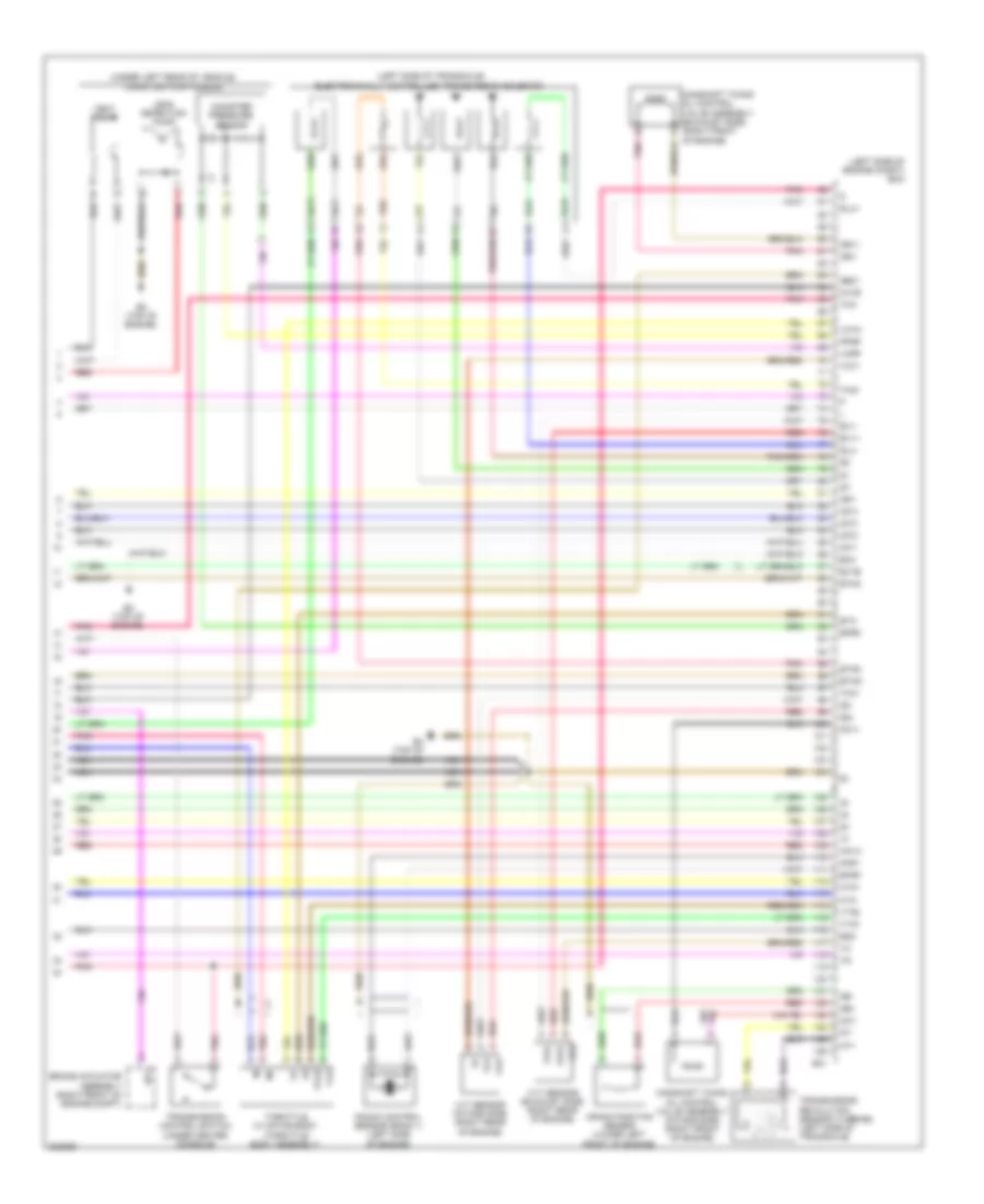
1.8L
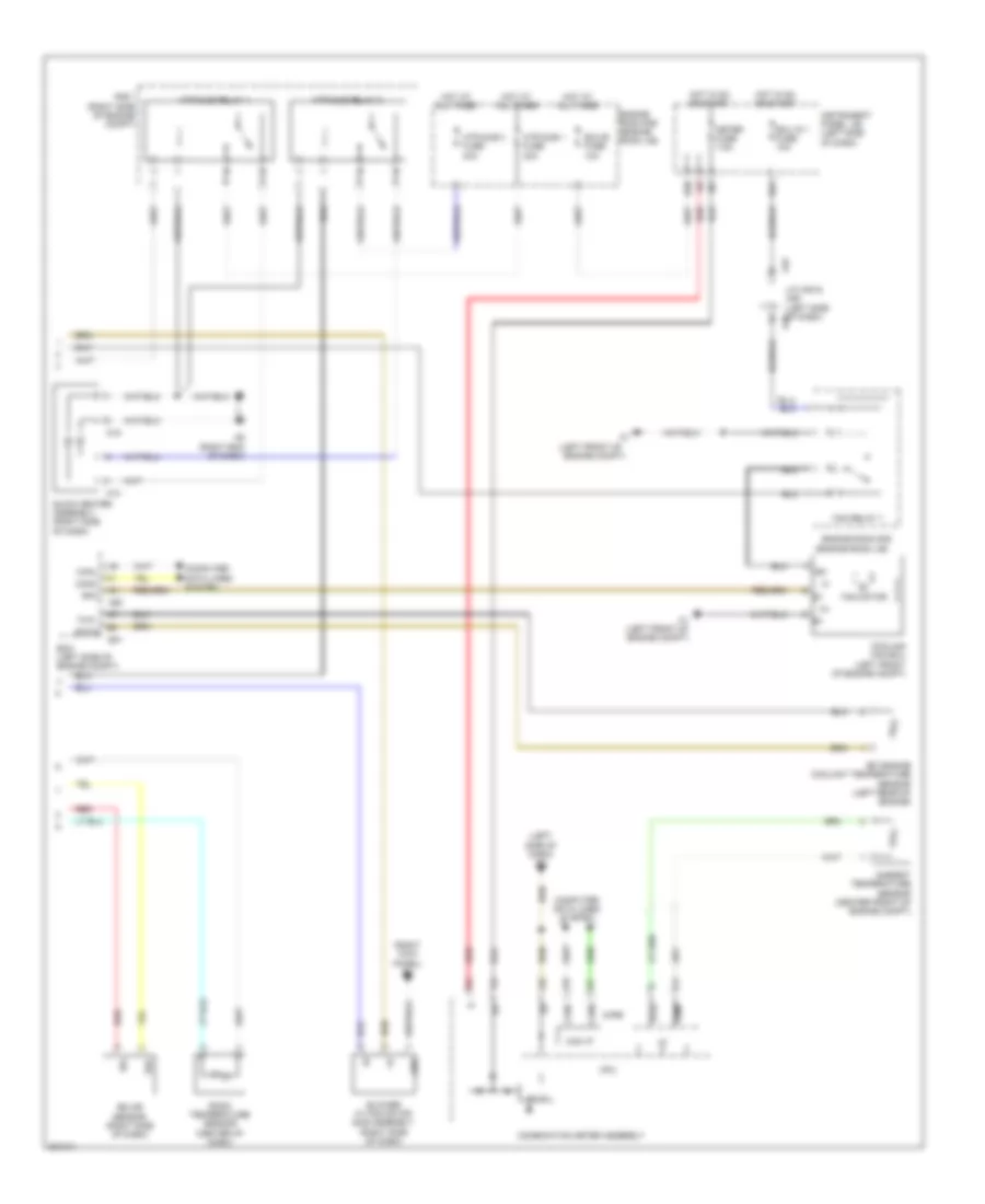
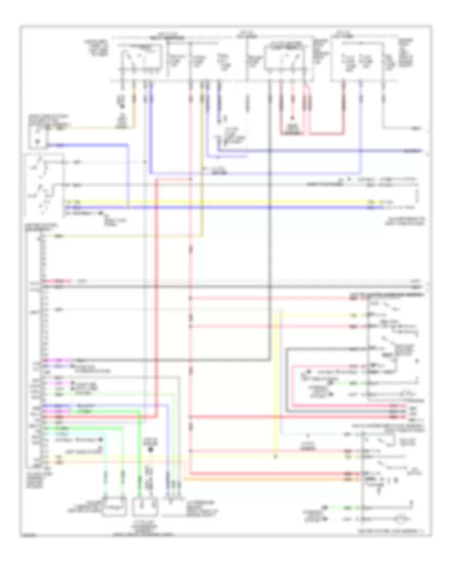
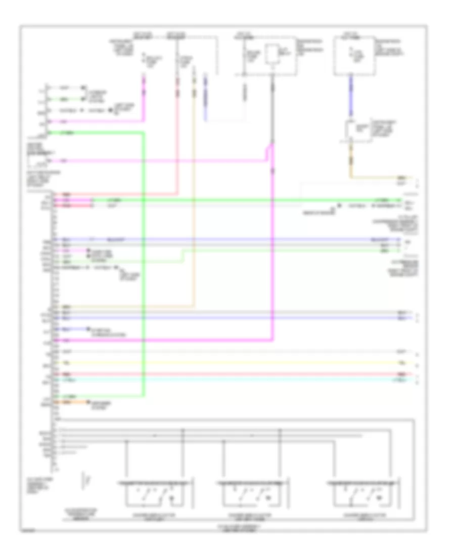
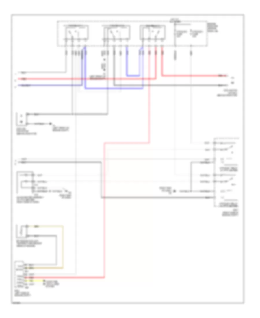
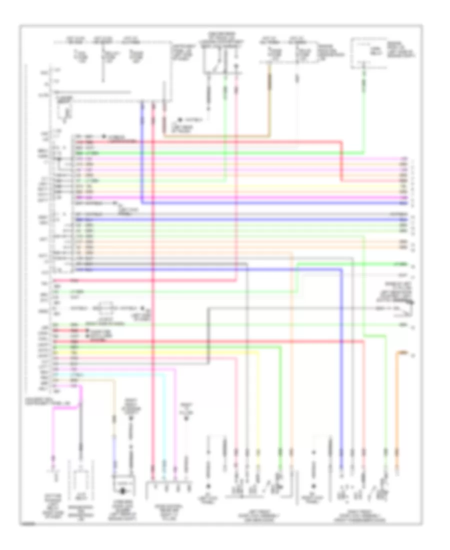
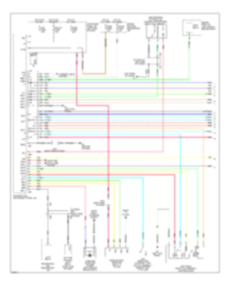
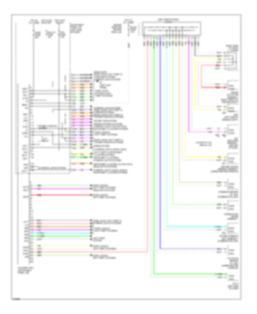
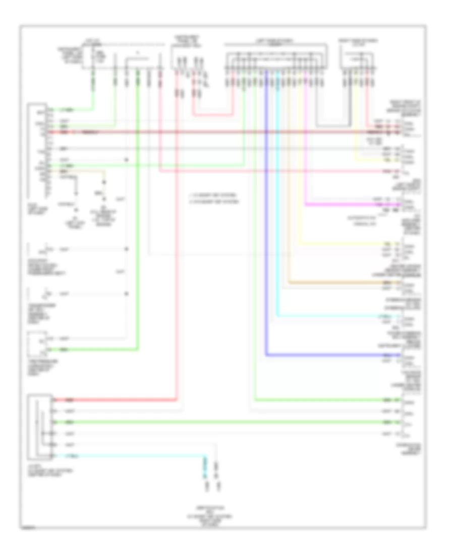
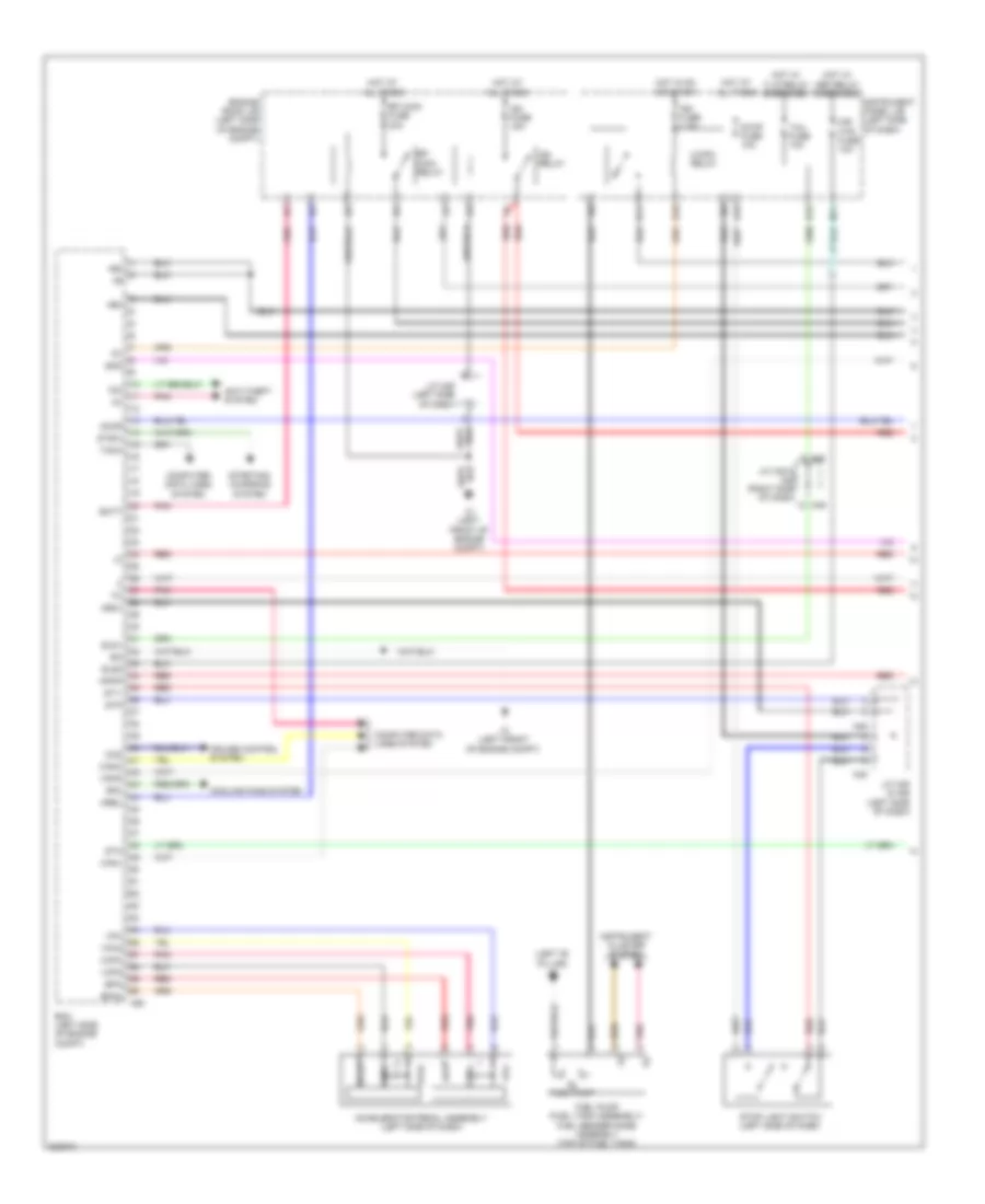
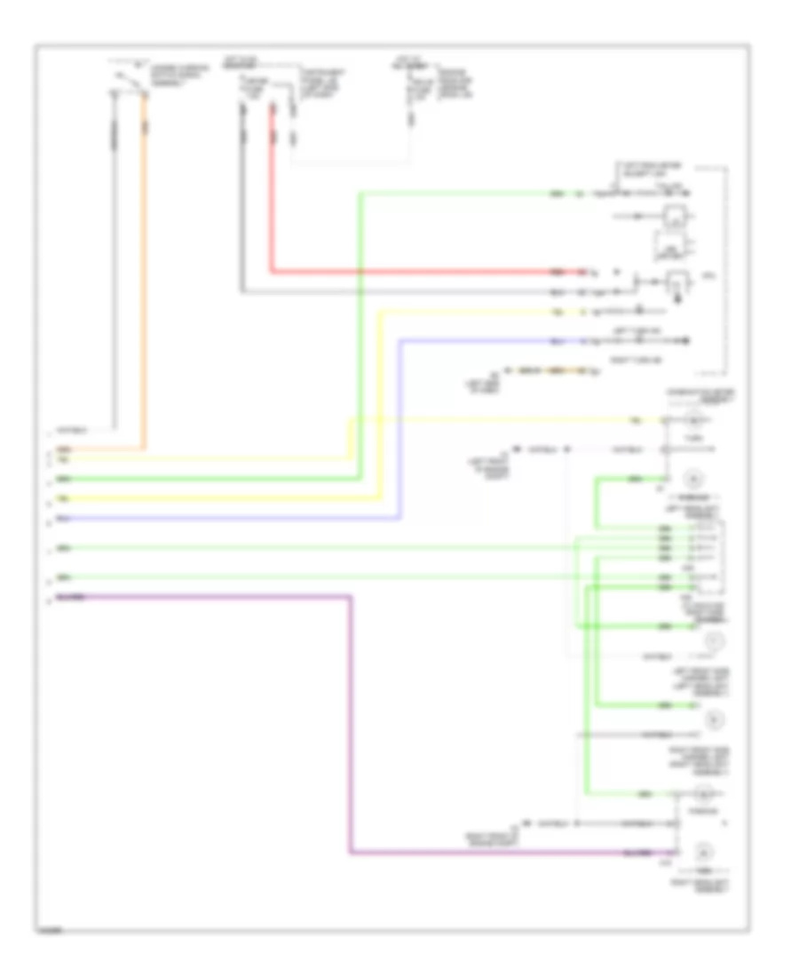
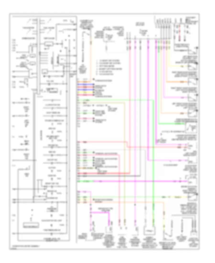
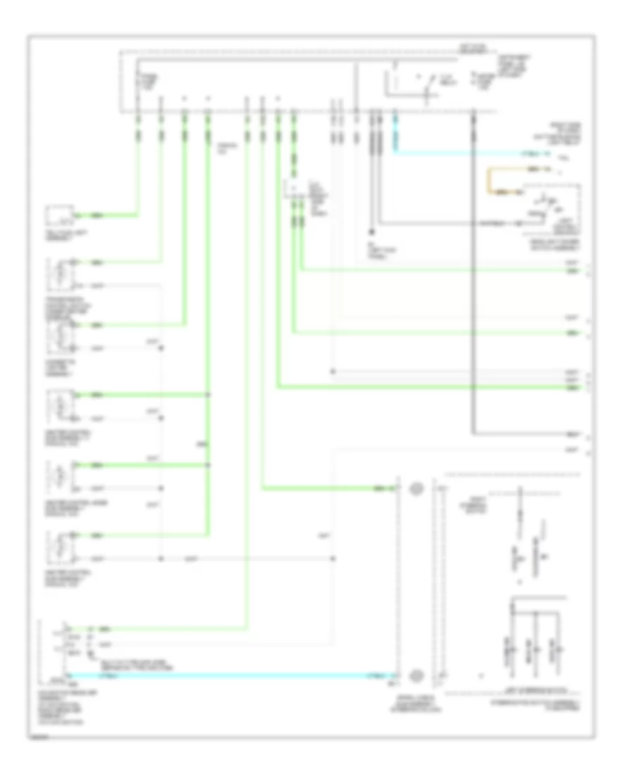
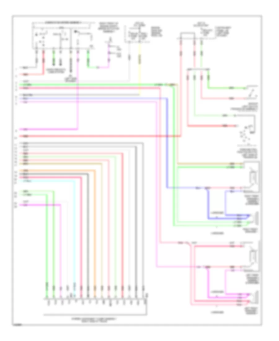
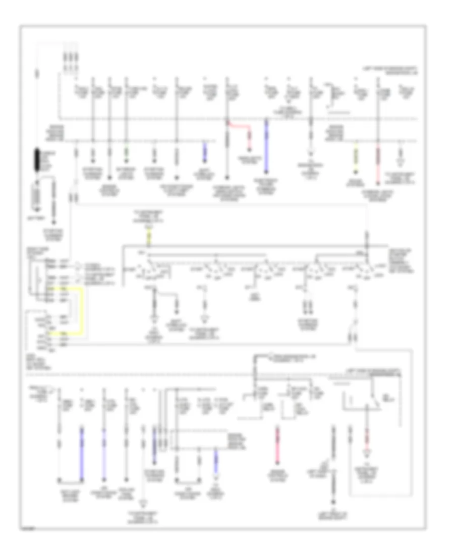
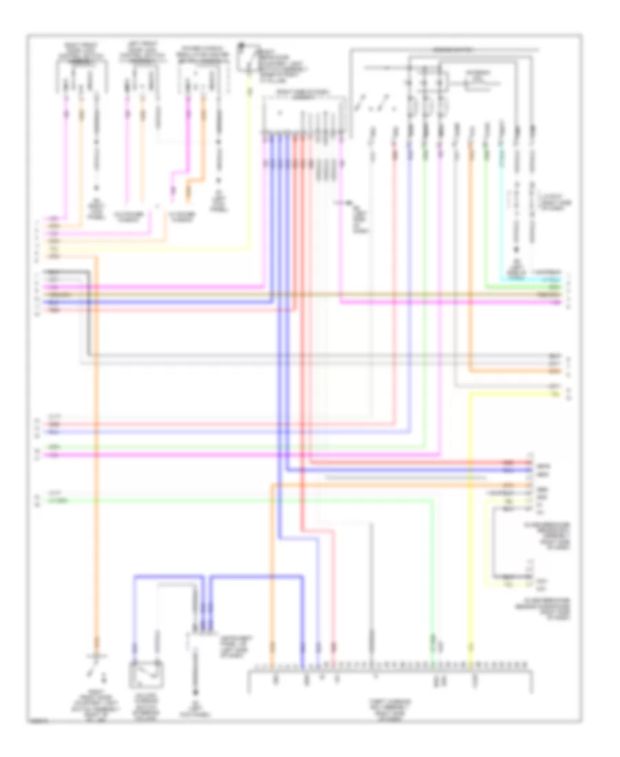
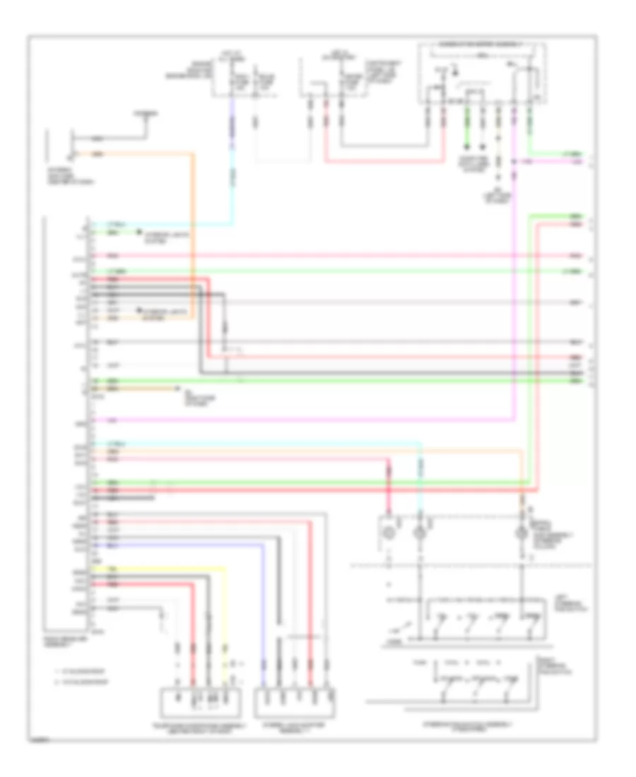
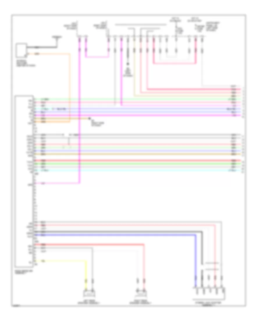
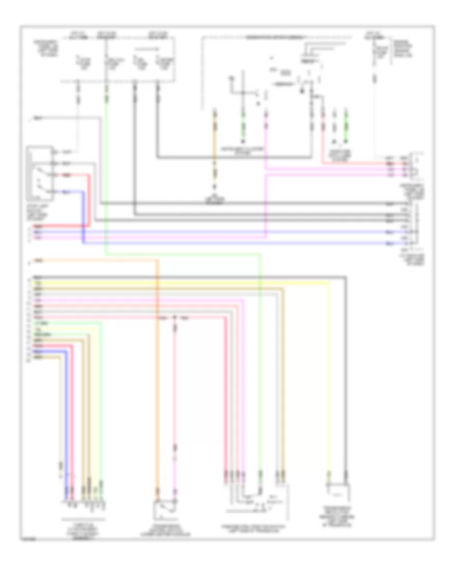
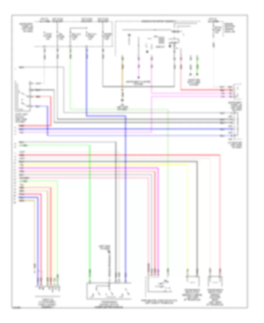
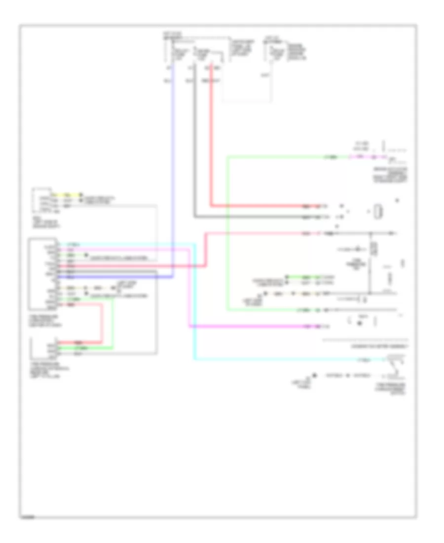
1.8L, Automatic A/C Wiring Diagram, NUMMI Made (1 of 2) for Toyota Corolla 2010
 https://portal-diagnostov.com/license.html
Automotive Electricians Portal FZCO
Automotive Electricians Portal FZCO
https://portal-diagnostov.com/license.html
https://portal-diagnostov.com/license.html
Automotive Electricians Portal FZCO
Automotive Electricians Portal FZCO
List of elements for 1.8L, Automatic A/C Wiring Diagram, NUMMI Made (1 of 2) for Toyota Corolla 2010:
- (left side of dash) e2
- (right front of engine compt) w/ pulley compressor assembly
- A/c amplifier assembly (center of dash)
- A/c blower assembly (center of dash)
- A/c evaporator temperature sensor
- A/c pressure sensor (right front of engine compt)
- Alt
- B bus
- B25
- B3 (top of engine)
- Blw
- Bus
- Bus g
- Canh
- Canl
- Computer data lines system
- Connector housing color (black)
- Connector housing color (red)
- Damper servo motor (air inlet)
- Damper servo motor (air mix)
- Damper servo motor (air vent mode)
- Daytime running light relay (right side of dash)
- Defogger system
- E2 (left side of dash)
- E30
- Ecu-b2 fuse 10a
- Ecu-ig 2 fuse 10a
- Engine room j/b (left side of engine compt)
- Engine room r/b (engine room j/b)
- Gnd
- H-lp
- H-lp relay
- Heater control sub-assembly
- Hls
- Hot at all times
- Hot in on or start
- Htr fuse 50a
- Htr-ig fuse 10a
- Ig+
- Ill+
- Ill-
- Instrument panel j/b (left side of dash)
- Interior lights system
- Lin1
- Pnk
- Pre
- Ptc1
- Ptc2
- Q10
- Rdfg
- Rdi fuse 40a
- Red
- S5-3
- S5-4
- Sg-1
- Sg-2
- Sga
- Short pin
- Sol+
- Sol-
- Starting/ charging system
- Tea
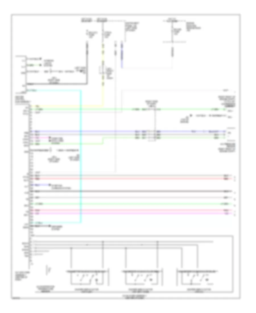
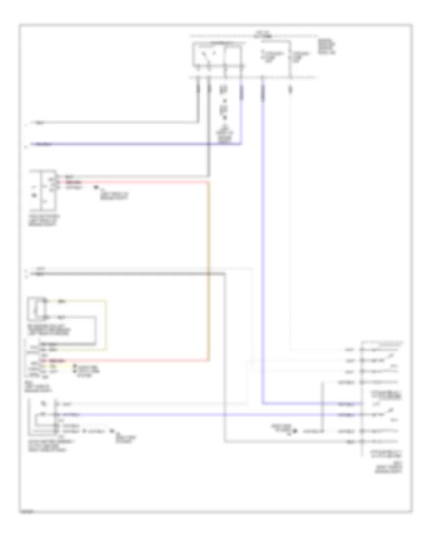
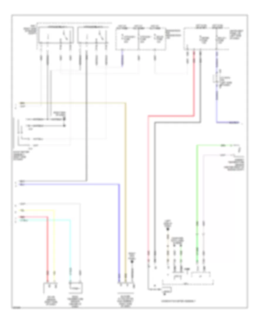
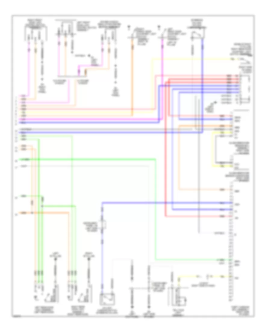
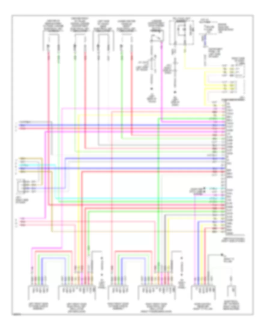
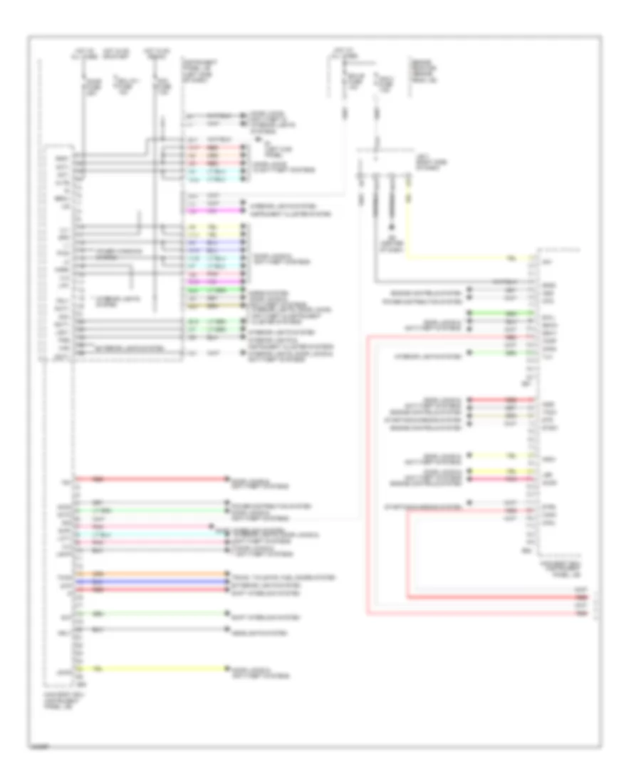
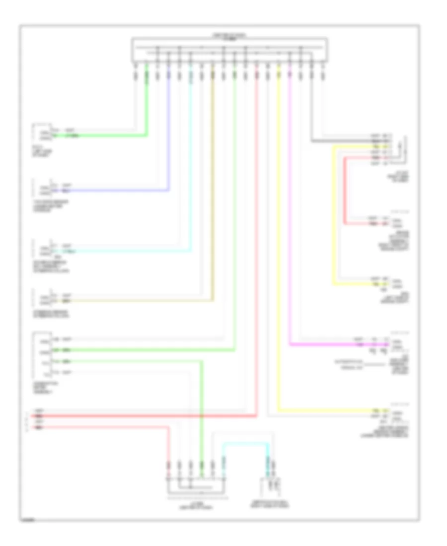
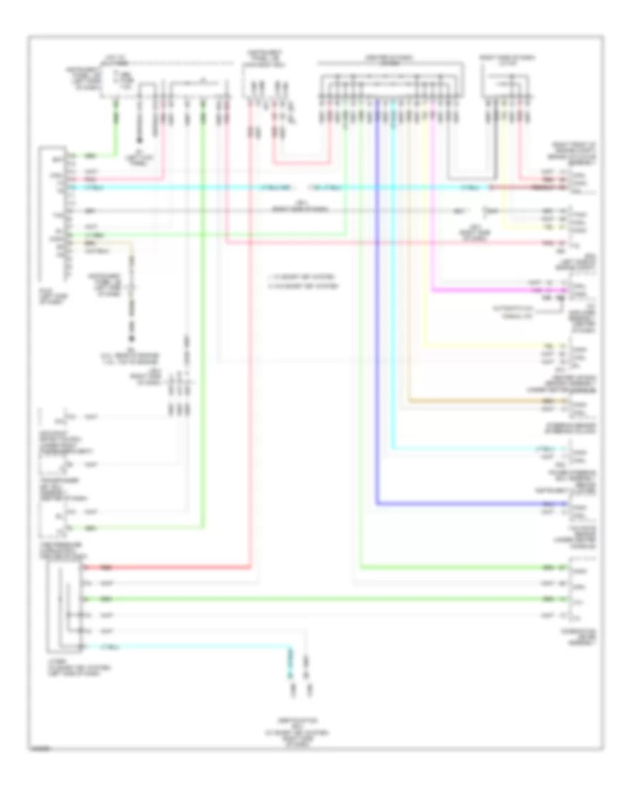
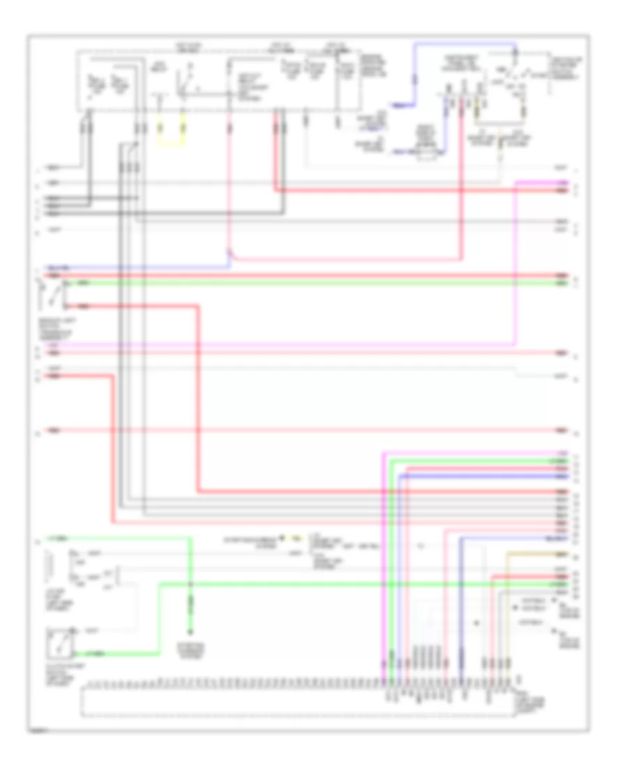
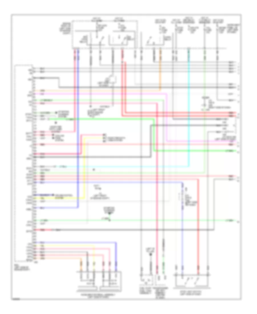
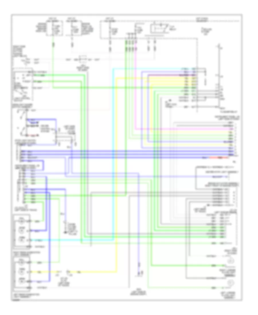
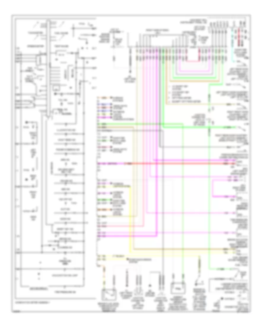
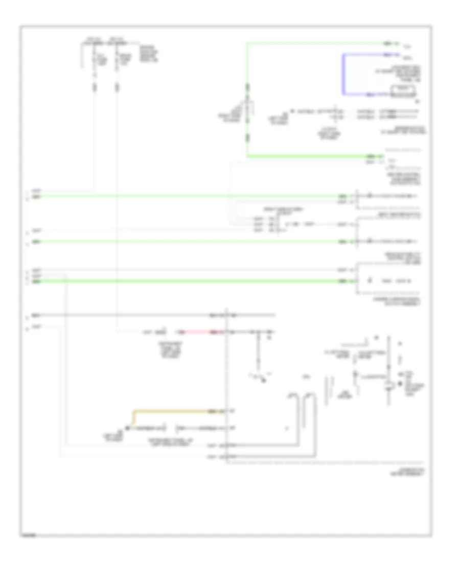
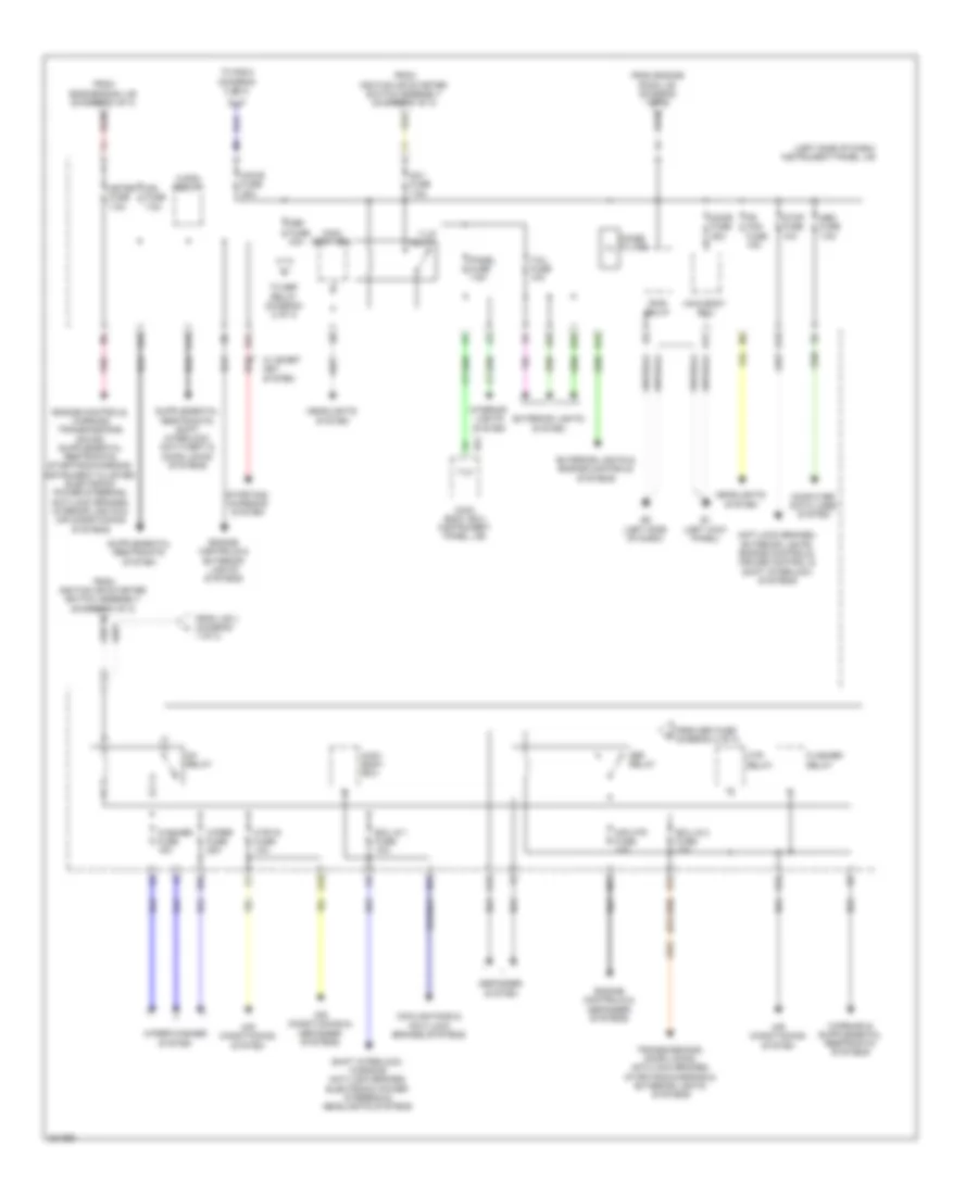
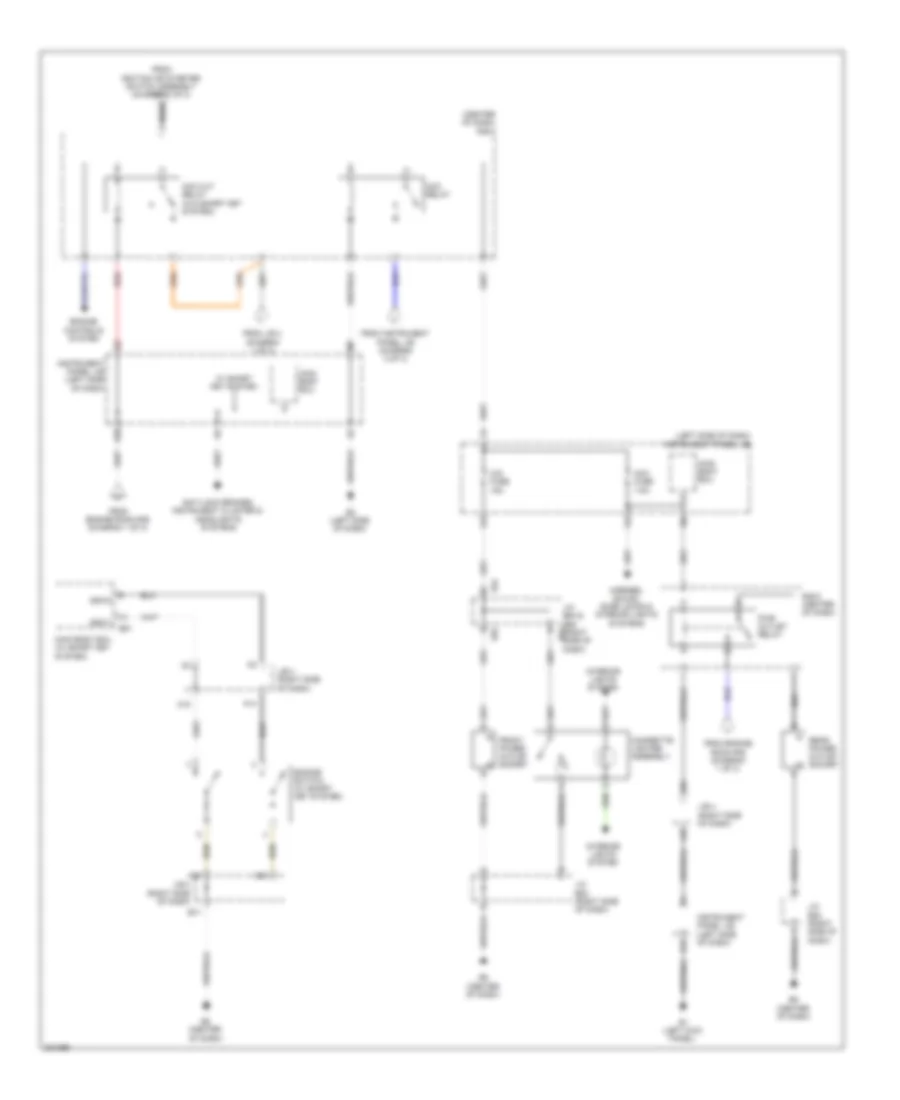
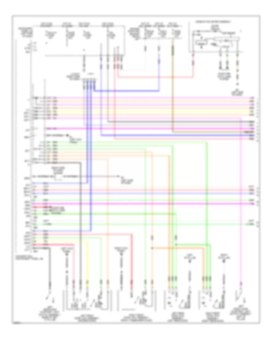
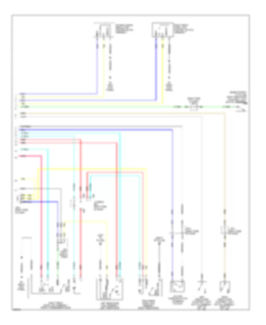
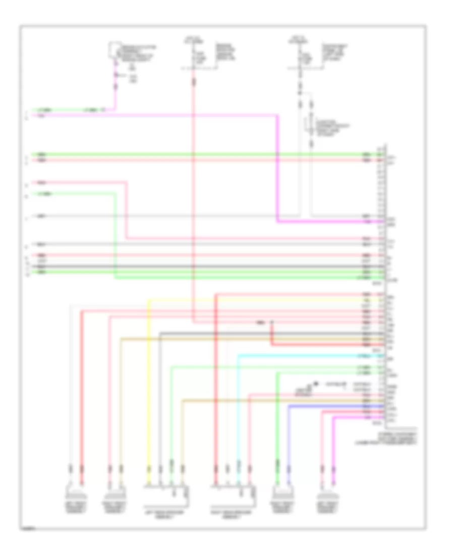
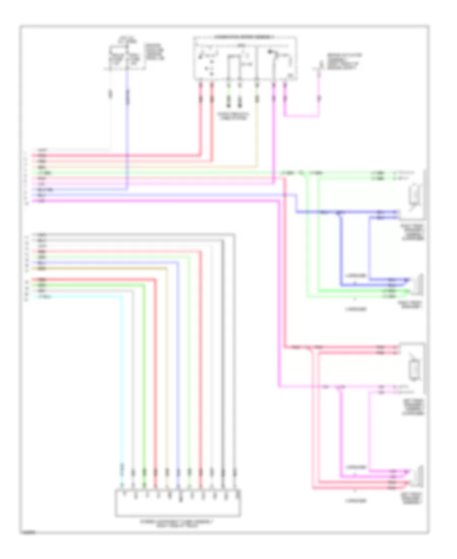
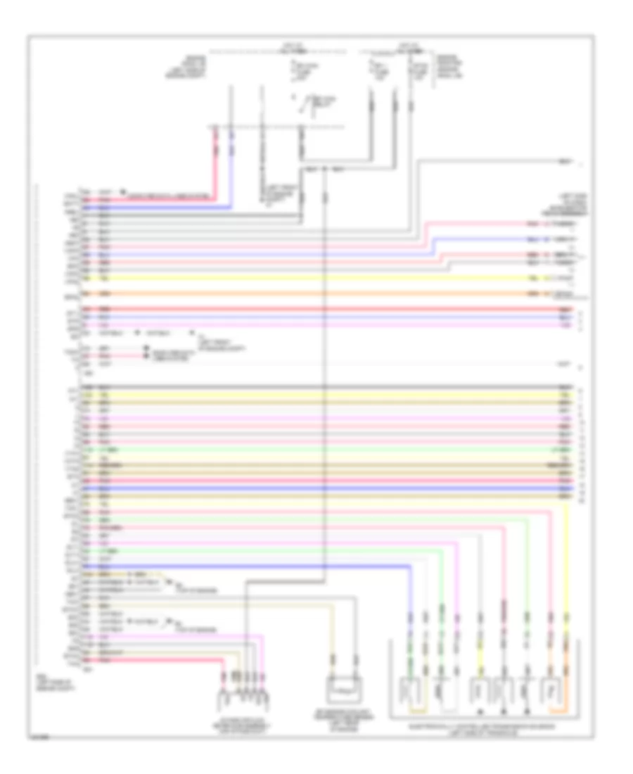
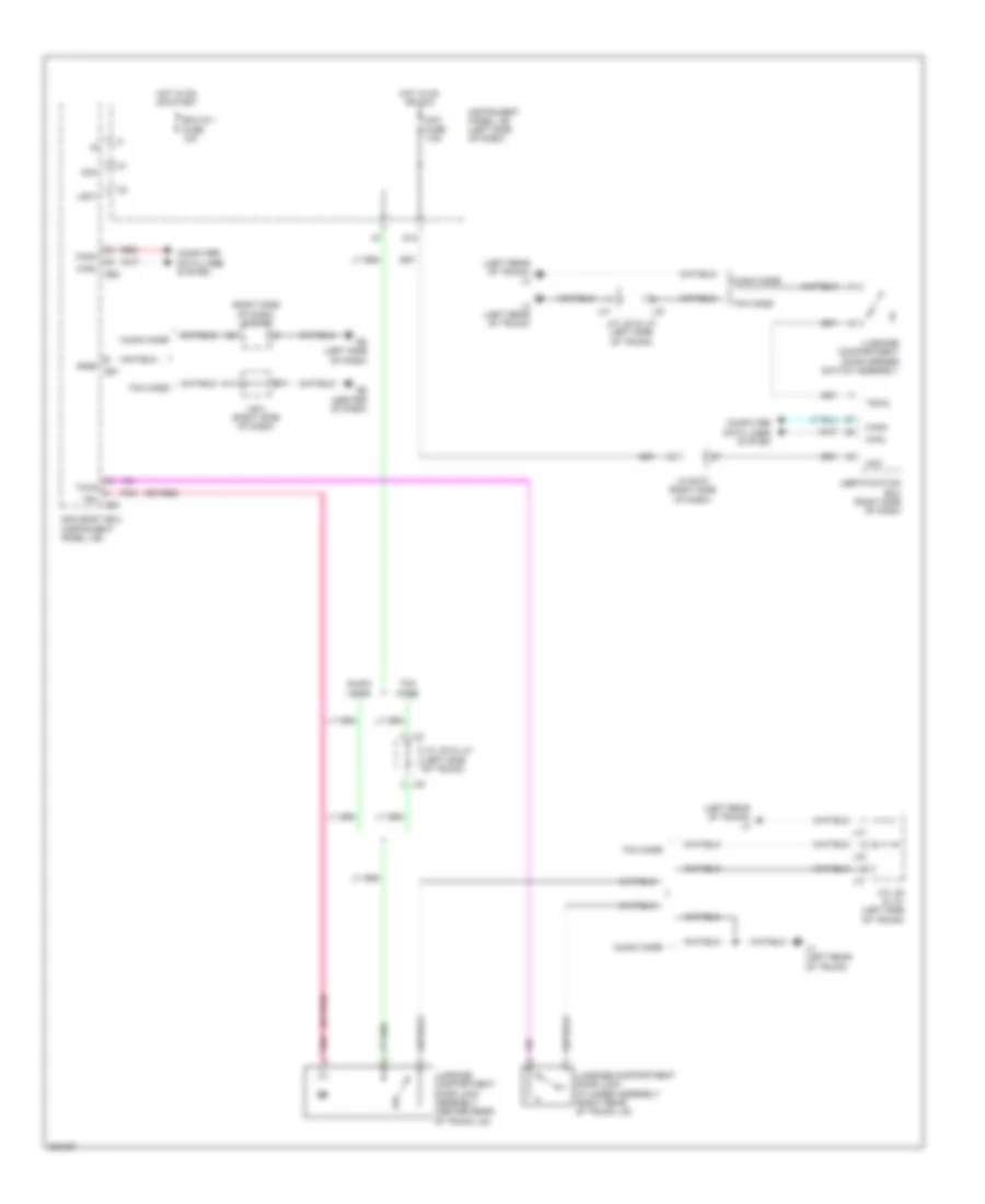
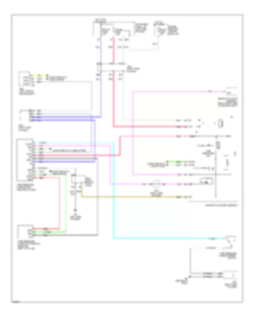
1.8L, Automatic A/C Wiring Diagram, NUMMI Made (2 of 2) for Toyota Corolla 2010
List of elements for 1.8L, Automatic A/C Wiring Diagram, NUMMI Made (2 of 2) for Toyota Corolla 2010:
- (engine room j/b)
- (left front of
- (left side of dash) e2
- (right kick panel) e4
- +b1
- 5v ic
- 5v+b
- A1 (left front of engine compt)
- A14
- A15
- A45
- A50
- A6 (right end of dash)
- Ambient temperature sensor (center front of engine compt)
- B24
- B30
- B31
- Blower w/ fan motor sub assembly (right side of dash)
- Can i/f
- Canh
- Canl
- Combination meter assembly
- Computer data lines system
- Cooling fan ecu (left front of engine compt)
- Cpu
- Ecm (left side of engine compt)
- Ecu ig 1 fuse 10a
- Ecu-b fuse 10a
- Efi engine coolant temperature sensor (left rear of engine)
- Engine compt)
- Engine room r/b
- Engine room r/b (engine room j/b)
- Ethw
- Fan motor
- Fan relay 1
- Gnd
- Hot at all times
- Hot in on or start
- Htr sub 1 fuse 30a
- Htr sub 3 fuse 30a
- Htr sub relay 1
- Htr sub relay 3
- I/f
- Ig+
- Instrument panel j/b (left side of dash)
- J/c a45 & a46 (left side of dash) a46
- Meter fuse 7.5a
- Quick heater assembly (right side of dash)
- R/b 7 (right side of engine compt)
- Red
- Rfc
- Room temperature sensor (center of dash)
- Solar sensor (right side of dash)
- Ss+
- Ss-
- Temp
- Thw
- Tx1+
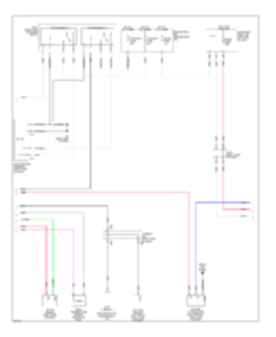
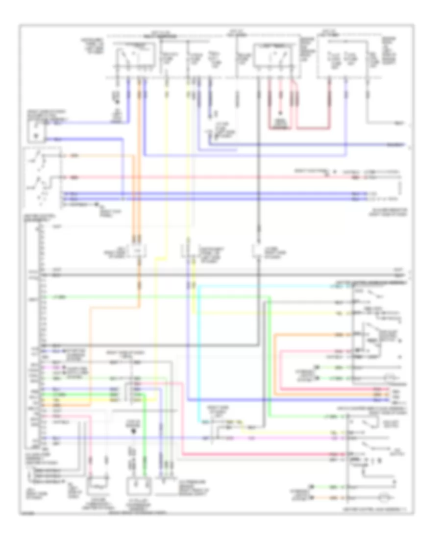
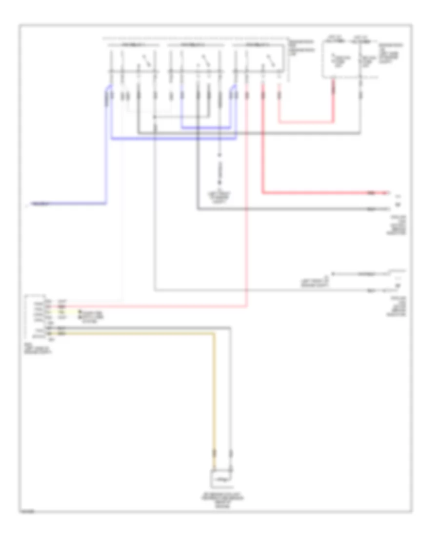
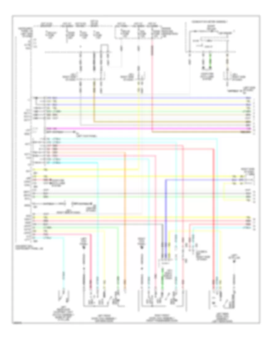
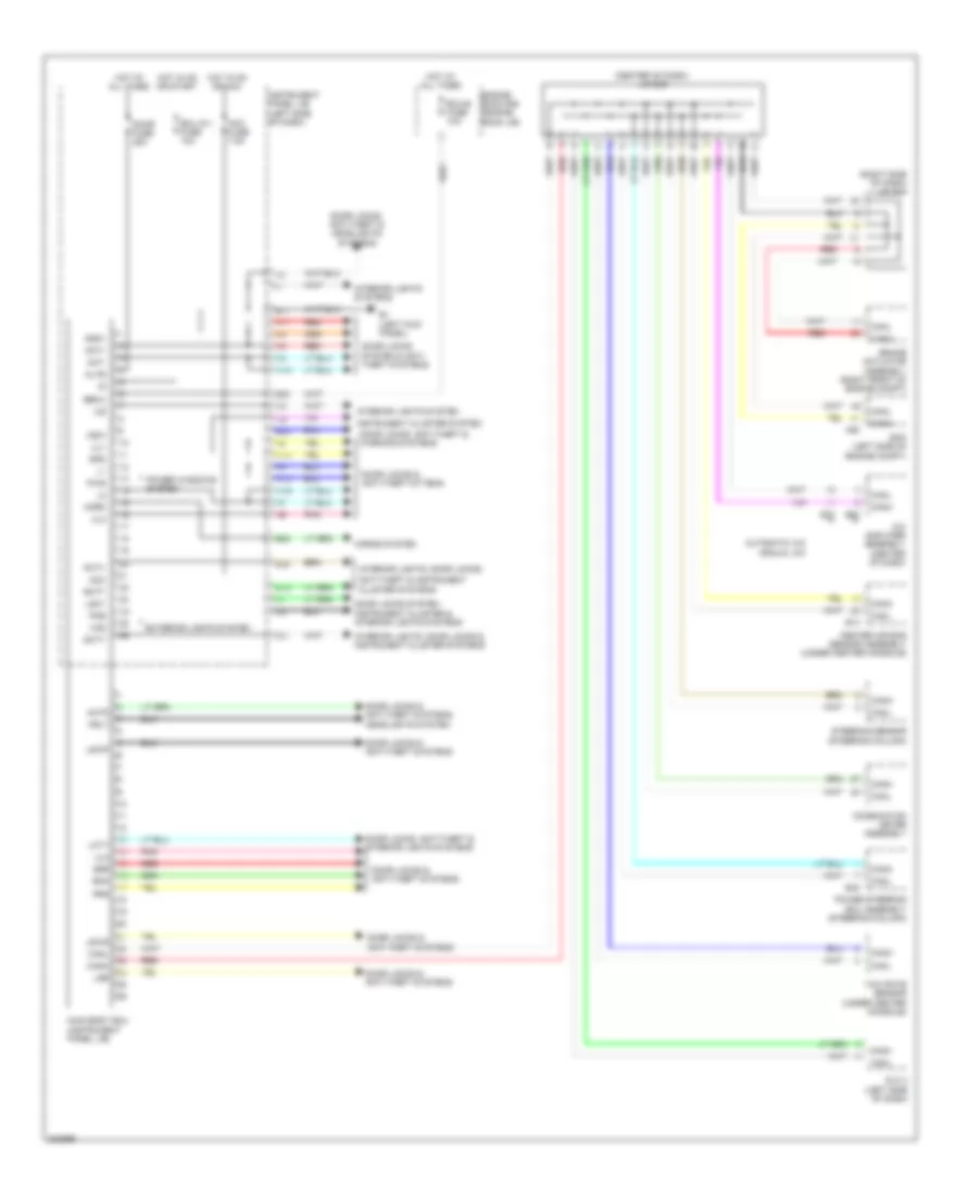
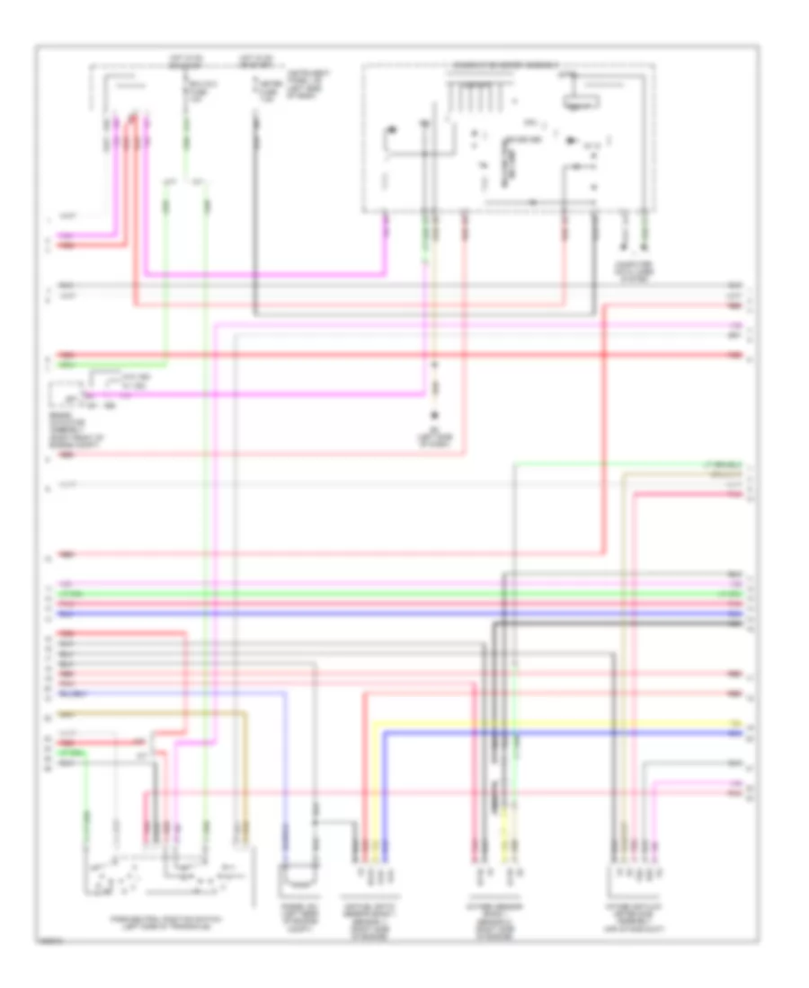
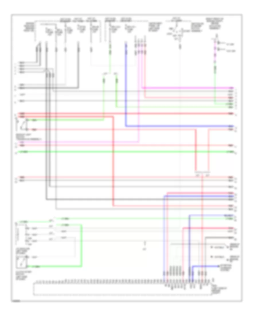
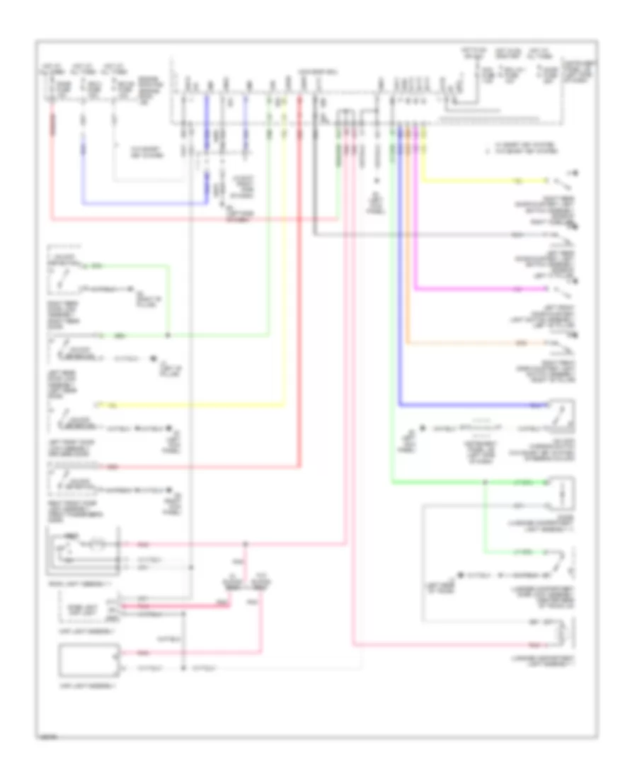
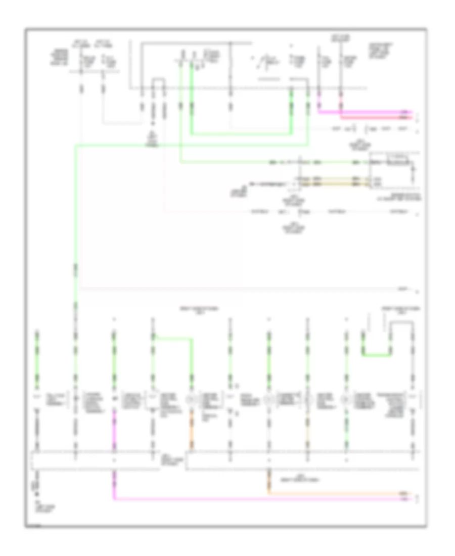
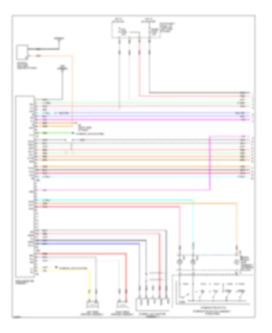
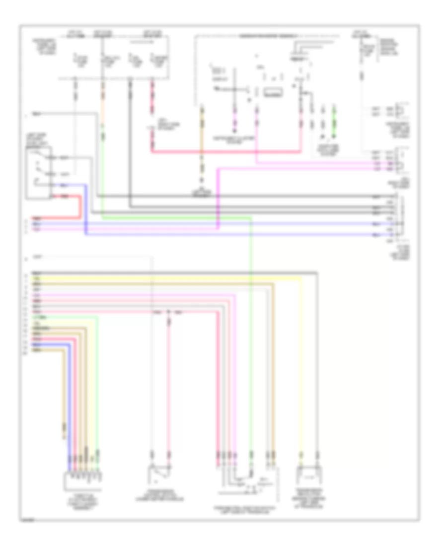
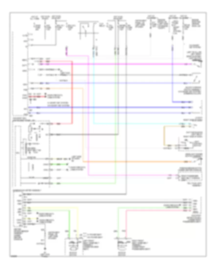
1.8L, Automatic A/C Wiring Diagram, TMC Made (1 of 3) for Toyota Corolla 2010
List of elements for 1.8L, Automatic A/C Wiring Diagram, TMC Made (1 of 3) for Toyota Corolla 2010:
- (left side of dash) e2
- (right front of engine compt) w/ pulley compressor assembly
- (right side of dash) j/b 4
- A/c amplifier assembly (center of dash)
- A/c blower assembly (center of dash)
- A/c evaporator temperature sensor
- A/c pressure sensor (right front of engine compt)
- A12
- Alt
- B bus
- B14
- B19
- B25
- B26
- B3 (top of engine)
- B38
- B40
- B41
- B42
- B45
- B48
- B52
- B53
- B54
- Blw
- Bus
- Bus g
- Canh
- Canl
- Computer data lines system
- Connector housing color (black)
- Connector housing color (red)
- Damper servo motor (air inlet)
- Damper servo motor (air mix)
- Damper servo motor (air vent mode)
- Defogger system
- E2 (left side of dash)
- E30
- Ecu-b2 fuse 10a
- Ecu-ig 2 fuse 10a
- Engine room r/b (engine room j/b)
- Gnd
- Heater control sub-assembly
- Hls
- Hot at all times
- Hot in on or start
- Htr-ig fuse 10a
- Ig+
- Ill+
- Ill-
- Instrument panel j/b (left side of dash)
- Interior
- J/b 4 (right side of dash)
- Lights system
- Lin1
- Pnk
- Pre
- Ptc1
- Ptc2
- Q10
- Rdfg
- Red
- S15
- S5-3
- S5-4
- Sg-1
- Sg-2
- Sga
- Sol+
- Sol-
- Starting/ charging system
- Tea
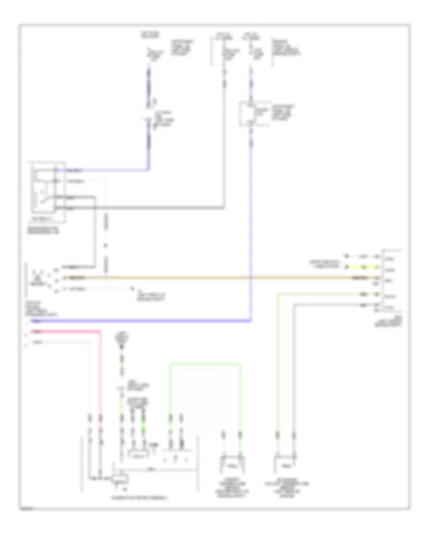
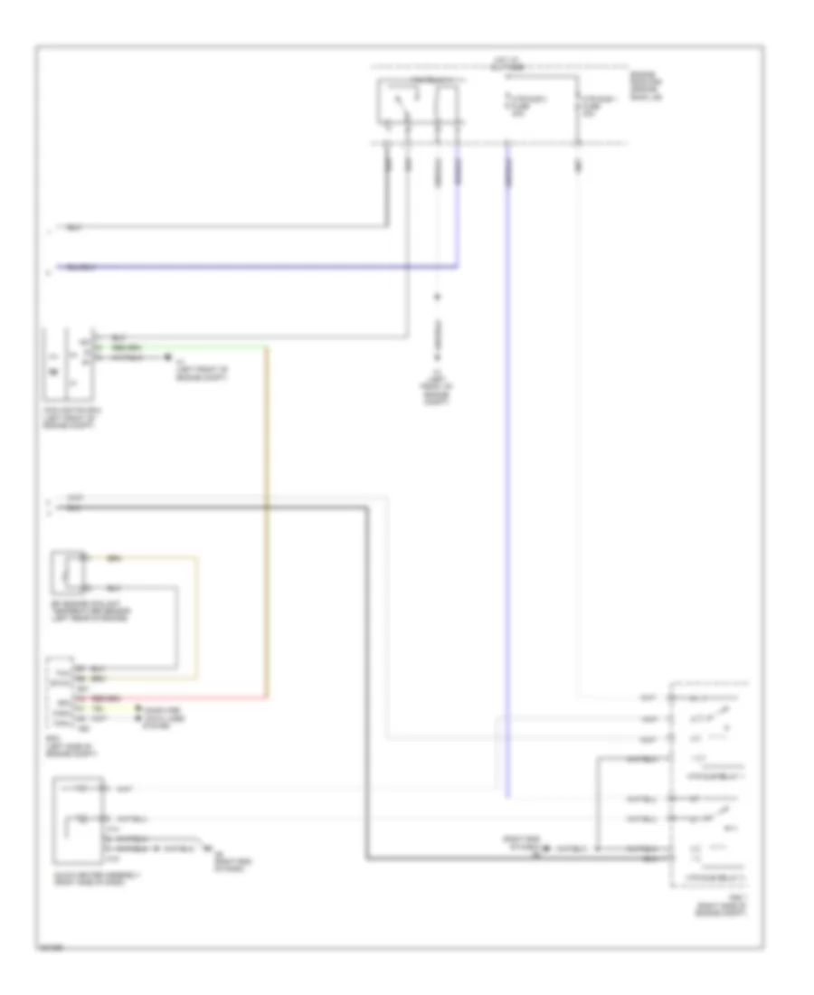
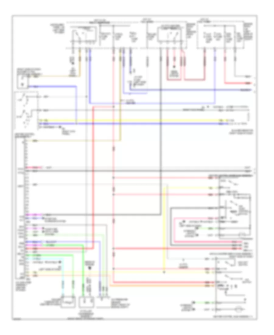
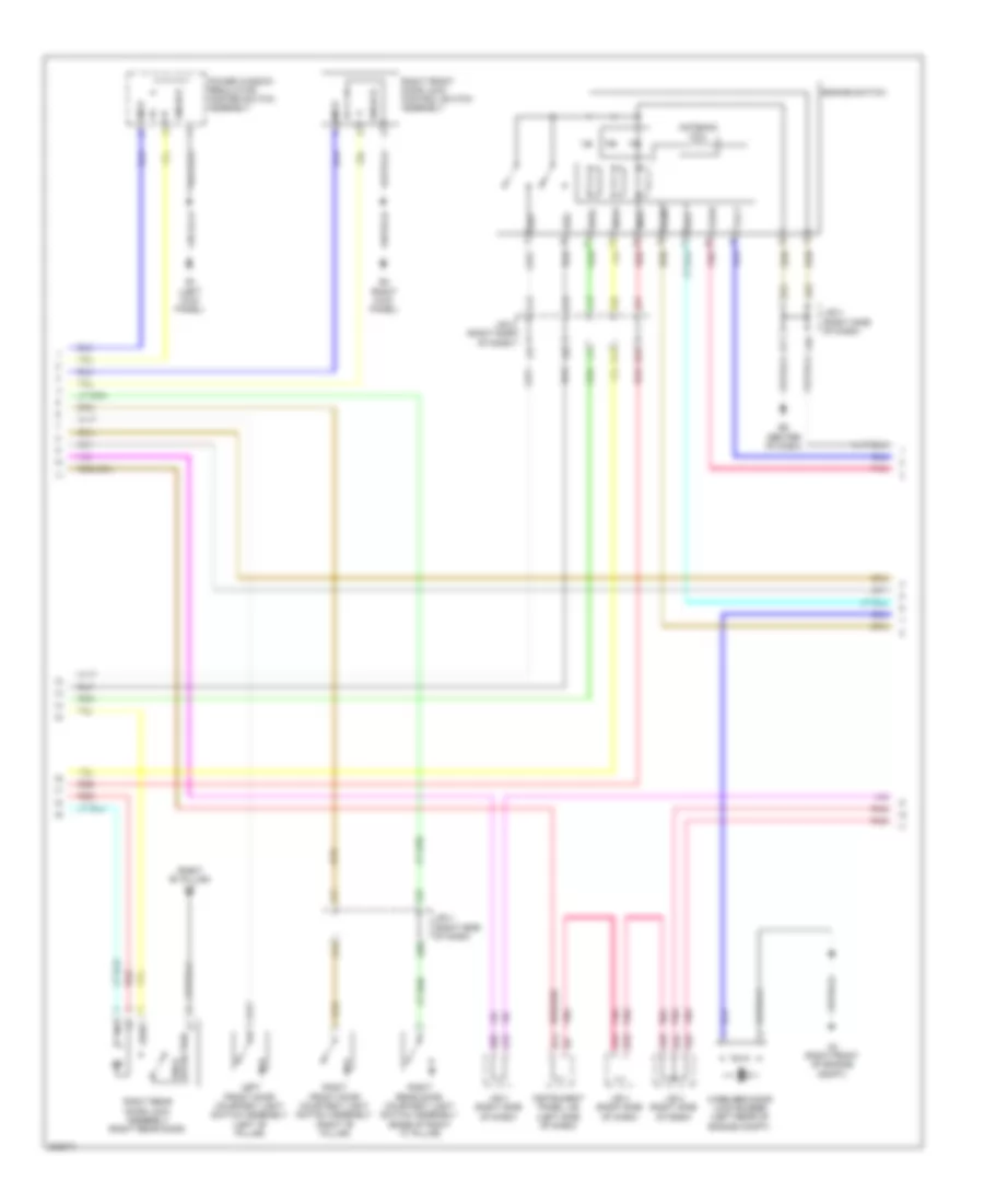
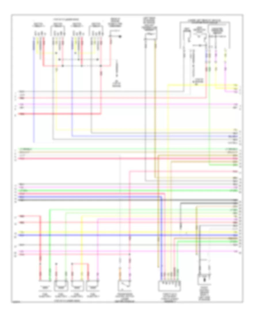
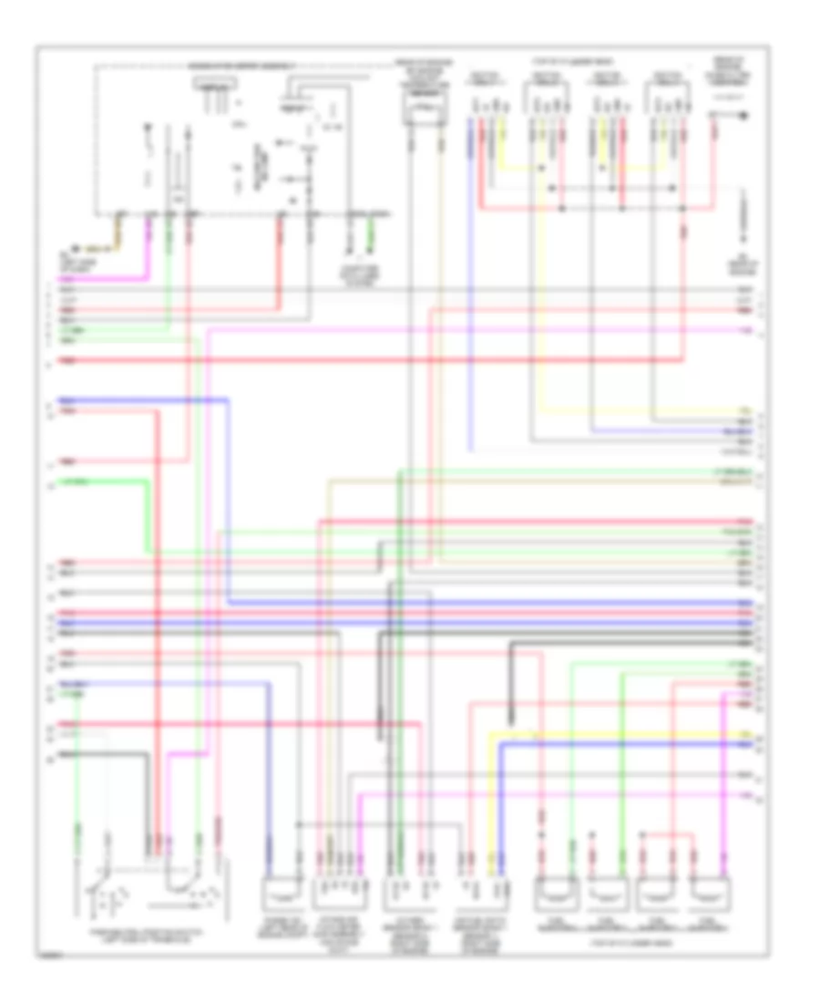
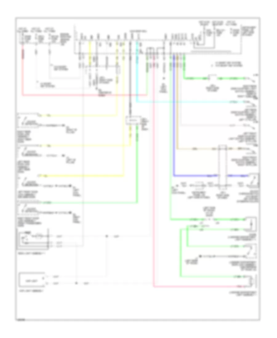
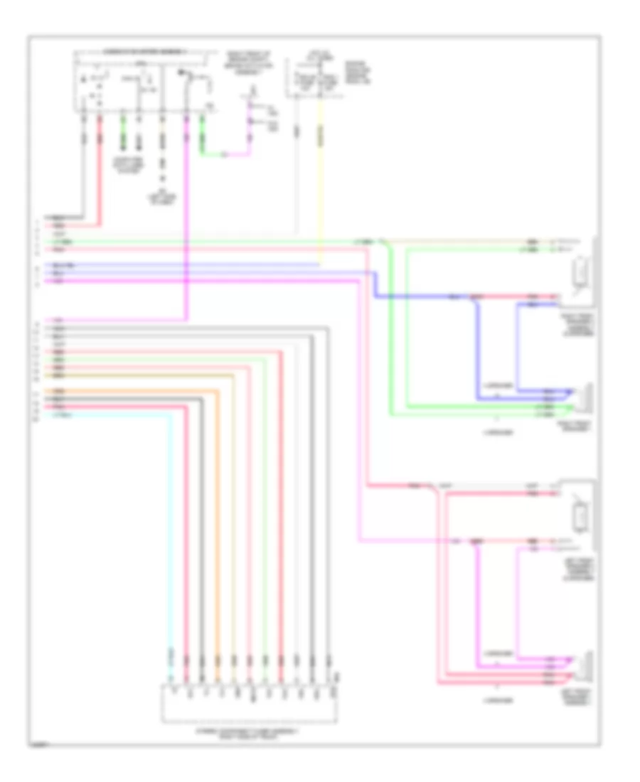
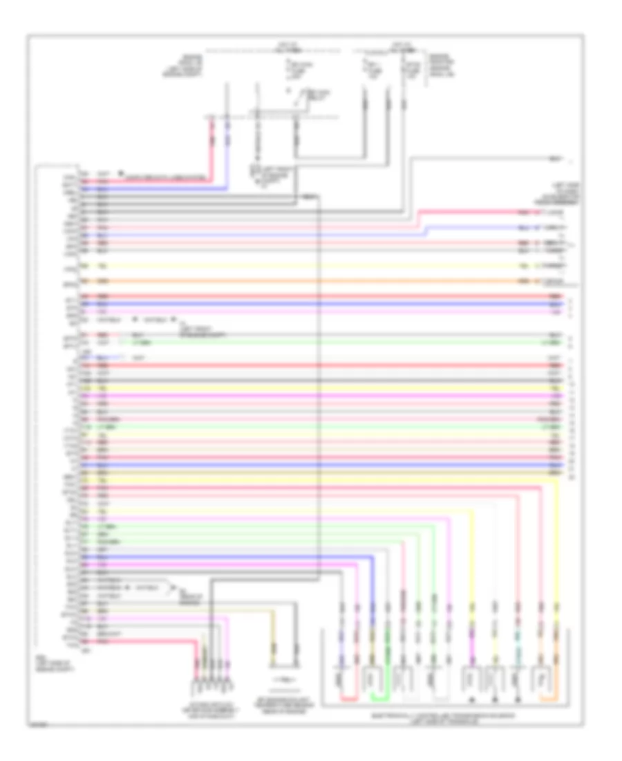
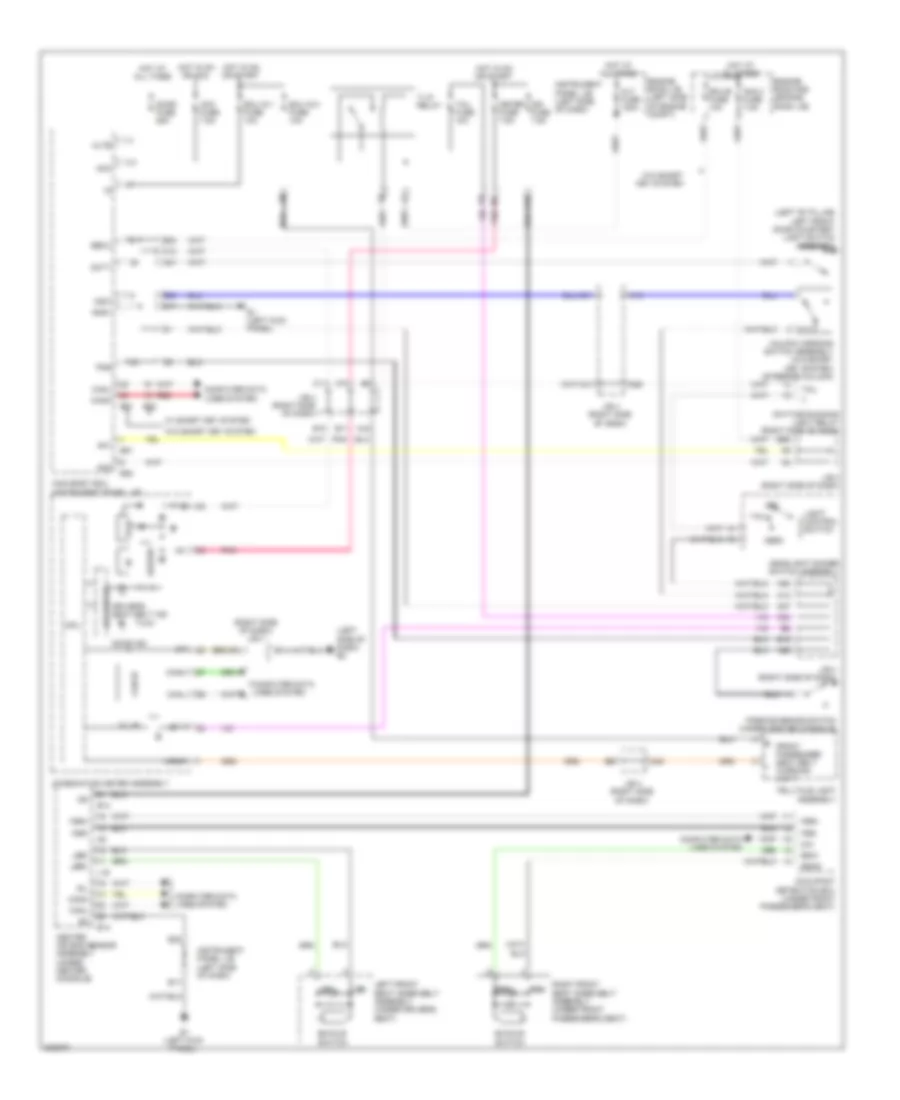
1.8L, Automatic A/C Wiring Diagram, TMC Made (2 of 3) for Toyota Corolla 2010
List of elements for 1.8L, Automatic A/C Wiring Diagram, TMC Made (2 of 3) for Toyota Corolla 2010:
- (right kick panel) e4
- A14
- A15
- A6 (right end of dash)
- A70
- B10
- B11
- B30
- Blower w/ fan motor sub assembly (right side of dash)
- C11
- Daytime running light relay (right side of dash)
- E56
- Ecu-b fuse 10a
- Engine room r/b (engine room j/b)
- Gnd
- H-lp
- H-lp relay
- H12
- Hot at all times
- Hot in on or start
- Htr sub 1 fuse 30a
- Htr sub 3 fuse 30a
- Htr sub relay 1
- Htr sub relay 3
- Instrument panel j/b (left side of dash)
- J/b 4 (right side of dash)
- J/c e56 & e57 (right side of dash) e57
- Meter fuse 7.5a
- Pnk
- Quick heater assembly (right side of dash)
- R/b 7 (right side of engine compt)
- Red
- Room temperature sensor (center of dash)
- Solar sensor (right side of dash)
- Ss+
- Ss-
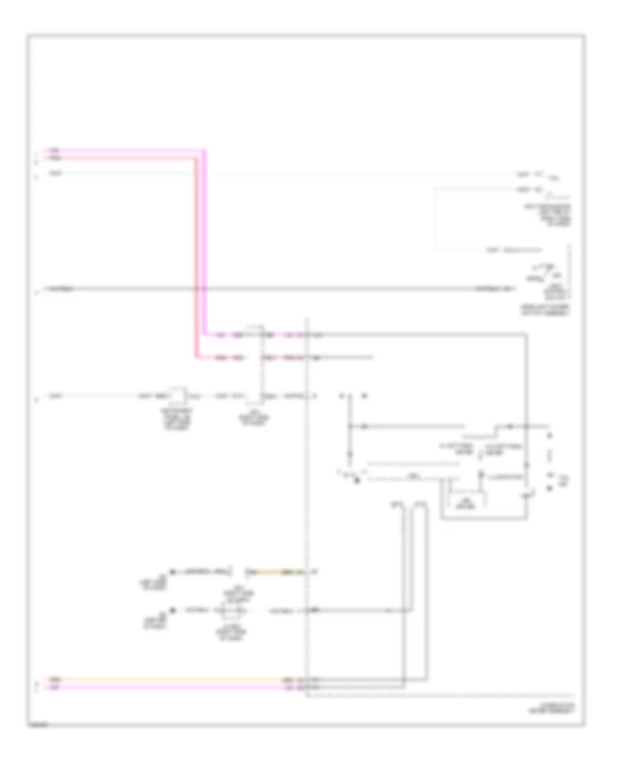
1.8L, Automatic A/C Wiring Diagram, TMC Made (3 of 3) for Toyota Corolla 2010
List of elements for 1.8L, Automatic A/C Wiring Diagram, TMC Made (3 of 3) for Toyota Corolla 2010:
- (left side of dash) e2
- +b1
- 5v ic
- 5v+b
- A1 (left front of engine compt)
- A45
- A50
- Ambient temperature sensor (center front of engine compt)
- B14
- B24
- B31
- Can i/f
- Canh
- Canl
- Combination meter assembly
- Computer data lines system
- Cooling fan ecu (left front of engine compt)
- Cpu
- Ecm (left side of engine compt)
- Ecu ig 1 fuse 10a
- Efi engine coolant temperature sensor (left rear of) engine)
- Engine room j/b (left side of engine compt)
- Engine room r/b (engine room j/b)
- Ethw
- Fan motor
- Fan relay 1
- Hot at all times
- Hot in on or start
- Htr fuse 50a
- I/f
- Ig+
- Instrument panel j/b (left side of dash)
- J/b 4 (right side of dash)
- J/c a45 & a46 (left side of dash) a46
- Pnk
- Rdi fan fuse 40a
- Rfc
- Short pin
- Temp
- Thw
- Tx1+
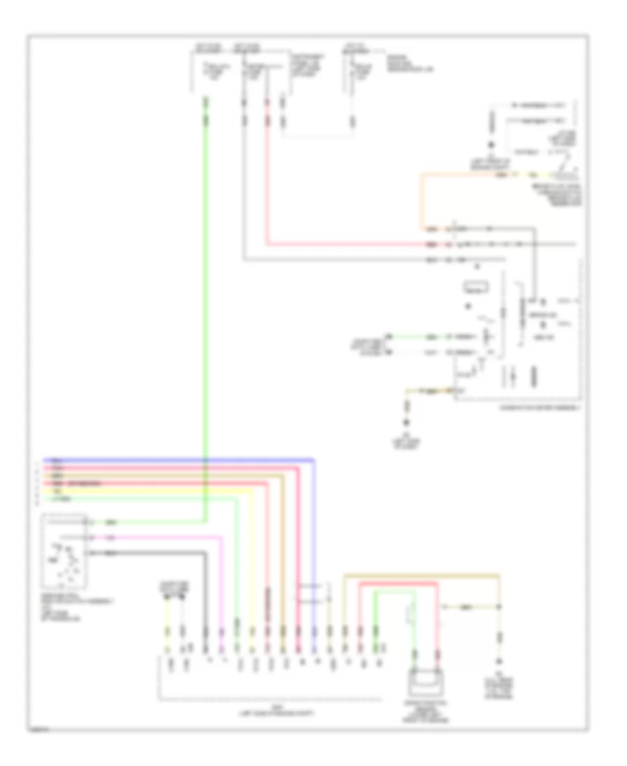
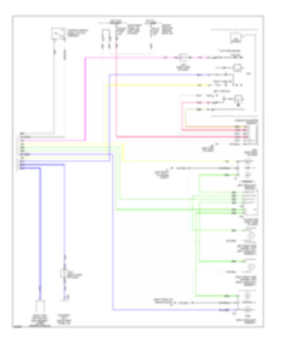
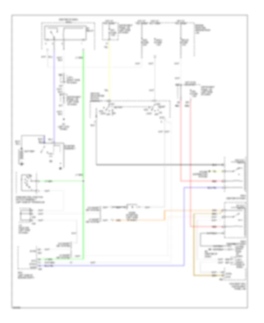
1.8L, Manual A/C Wiring Diagram, NUMMI Made (1 of 2) for Toyota Corolla 2010
List of elements for 1.8L, Manual A/C Wiring Diagram, NUMMI Made (1 of 2) for Toyota Corolla 2010:
- (right side of dash) blower w/ fan motor sub assembly
- (top of engine) b3
- (w/ ptc heater) h-lp relay
- A/c
- A/c amplifier assembly (center of dash)
- A/c pressure sensor (right front of engine compt)
- A/c switch
- A/c+
- A45
- Acid
- Aind
- Air inlet control switch
- Air mix damper servo sub assembly (right side of dash)
- Alt
- B24
- B25
- Blower resistor (right side of dash)
- Canh
- Canl
- Computer data lines system
- Cooler thermistor 1 (center of dash)
- Def-logic
- E1 (left kick panel)
- E17
- E2 (left side of dash)
- E4 (right kick panel)
- E62
- E63
- Ecu-
- Ecu-b2 fuse 10a
- Ecu-ig 2 fuse 10a
- Engine room j/b (left side of engine compt)
- Engine room r/b (engine room j/b)
- F/d
- Free
- Frs
- Gnd
- H-lp main fuse 50a
- Head- lights system
- Heat
- Heater control base sub assembly
- Heater control sub assembly
- Heater control sub assembly 3
- Hls
- Hot at all times
- Hot w/ ig1 relay energized
- Htr fuse 50a
- Htr relay
- Htr-ig fuse 10a
- Ig 1 fuse 10a
- Ig+
- Ill+
- Ill-
- Instrument panel j/b (left side of dash)
- Interior lights system
- J/c a45 & a46 (left side of dash) a46
- Led
- Led+
- Lock
- Max hot switch
- Pnk
- Pre
- Ptc1
- Ptc2
- Q10
- Rdi fan fuse 40a
- Rec
- Red
- S5-3
- Sblw
- Sg-2
- Sg-3
- Sol+
- Sol-
- Starting/ charging system
- W/ ptc heater
- W/ pulley compressor assembly (right front of engine compt)
1.8L, Manual A/C Wiring Diagram, NUMMI Made (2 of 2) for Toyota Corolla 2010
List of elements for 1.8L, Manual A/C Wiring Diagram, NUMMI Made (2 of 2) for Toyota Corolla 2010:
- (right end of dash) a6
- +b1
- A1 (left front of engine compt)
- A14
- A15
- A50
- A6 (right end of dash)
- B31
- Canh
- Canl
- Computer
- Cooling fan ecu (left front of engine compt)
- Data lines
- Ecm (left side of engine compt)
- Efi engine coolant temperature sensor (left rear of engine)
- Engine room r/b (engine room j/b)
- Ethw
- Fan relay 1
- Hot at all times
- Htr sub 1 fuse 30a
- Htr sub 3 fuse 30a
- Htr sub relay 1 (w/ ptc heater)
- Htr sub relay 3 (w/ ptc heater)
- Quick heater assembly (w/ ptc heater) (right side of dash)
- R/b 7 (right side of engine compt)
- Rfc
- System
- Thw
1.8L, Manual A/C Wiring Diagram, TMC Made (1 of 2) for Toyota Corolla 2010
List of elements for 1.8L, Manual A/C Wiring Diagram, TMC Made (1 of 2) for Toyota Corolla 2010:
- (right kick panel) e4
- (right side of dash) blower w/ fan motor sub assembly
- (right side of dash) j/b 4
- (top of engine) b3
- A/c
- A/c amplifier assembly (center of dash)
- A/c pressure sensor (right front of engine compt)
- A/c switch
- A/c+
- A12
- A45
- A67
- A78
- Acid
- Aind
- Air inlet control switch
- Air mix damper servo sub assembly (right side of dash)
- Alt
- B14
- B18
- B19
- B24
- B25
- B31
- B33
- B34
- B37
- B38
- B40
- B41
- B42
- B43
- B45
- B48
- B52
- B53
- B54
- B56
- Blower resistor (right side of dash)
- Canh
- Canl
- Computer data lines system
- Cooler thermistor 1 (center of dash)
- Def-logic
- E1 (left kick panel)
- E17
- E2 (left side of dash)
- E4 (right kick panel)
- E62
- E63
- Ecu-
- Ecu-b2 fuse 10a
- Ecu-ig 2 fuse 10a
- Engine room j/b (left side of engine compt)
- Engine room r/b (engine room j/b)
- F/d
- Free
- Frs
- Gnd
- H-lp main fuse 50a
- H-lp relay
- Head- lights system
- Heat
- Heater control base sub assembly
- Heater control sub assembly
- Heater control sub assembly 3
- Hls
- Hot at all times
- Hot w/ ig1 relay energized
- Htr fuse 50a
- Htr relay
- Htr-ig fuse 10a
- Ig 1 fuse 10a
- Ig+
- Ill+
- Ill-
- Instrument panel j/b (left side of dash)
- Interior lights system
- J/b 4 (right side of dash)
- J/c a45 & a46 (left side of dash) a46
- J/c e56 (right side of dash)
- Led
- Led+
- Lock
- Max hot switch
- Pnk
- Pre
- Ptc1
- Ptc2
- Q10
- Rdi fan fuse 40a
- Rec
- Red
- S5-3
- Sblw
- Sg-2
- Sg-3
- Sol+
- Sol-
- Starting/ charging system
- W/ pulley compressor assembly (right front of engine compt)
1.8L, Manual A/C Wiring Diagram, TMC Made (2 of 2) for Toyota Corolla 2010
List of elements for 1.8L, Manual A/C Wiring Diagram, TMC Made (2 of 2) for Toyota Corolla 2010:
- (right end of dash) a6
- +b1
- A1 (left front of engine compt)
- A14
- A15
- A50
- A6 (right end of dash)
- B31
- Canh
- Canl
- Computer
- Cooling fan ecu (left front of engine compt)
- Data lines
- Ecm (left side of engine compt)
- Efi engine coolant temperature sensor (left rear of engine)
- Engine room r/b (engine room j/b)
- Ethw
- Fan relay 1
- Hot at all times
- Htr sub 1 fuse 30a
- Htr sub 3 fuse 30a
- Htr sub relay 1
- Htr sub relay 3
- Quick heater assembly (right side of dash)
- R/b 7 (right side of engine compt)
- Rfc
- System
- Thw
2.4L
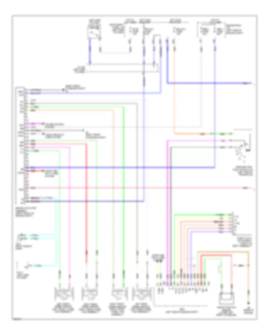
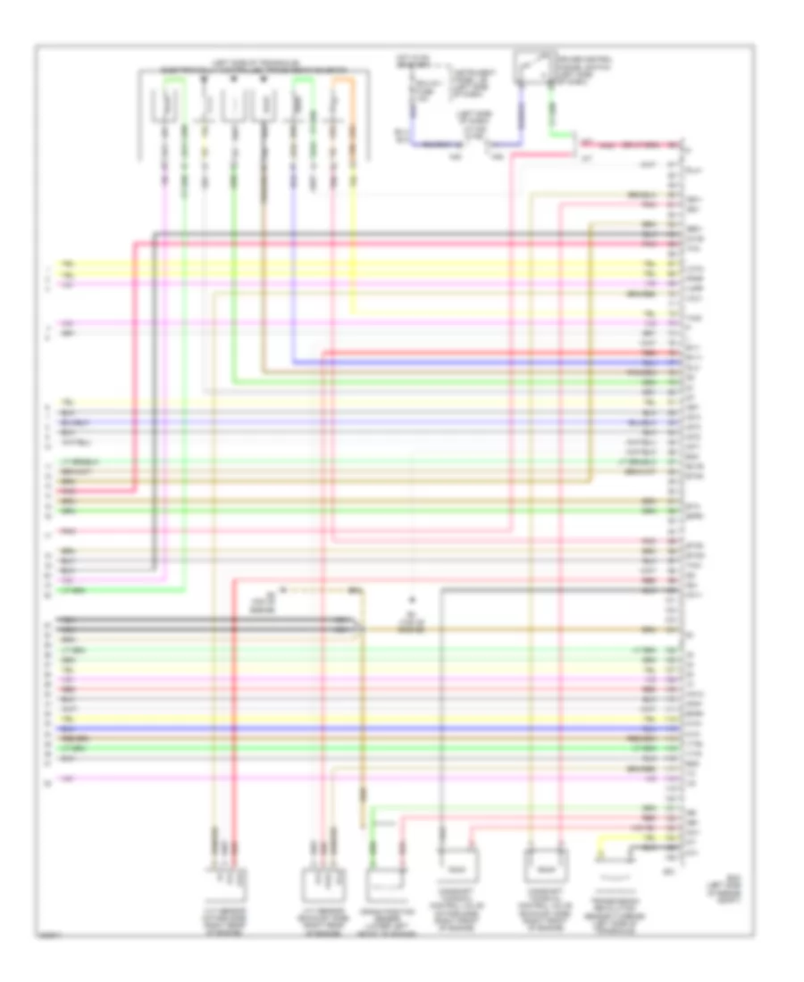
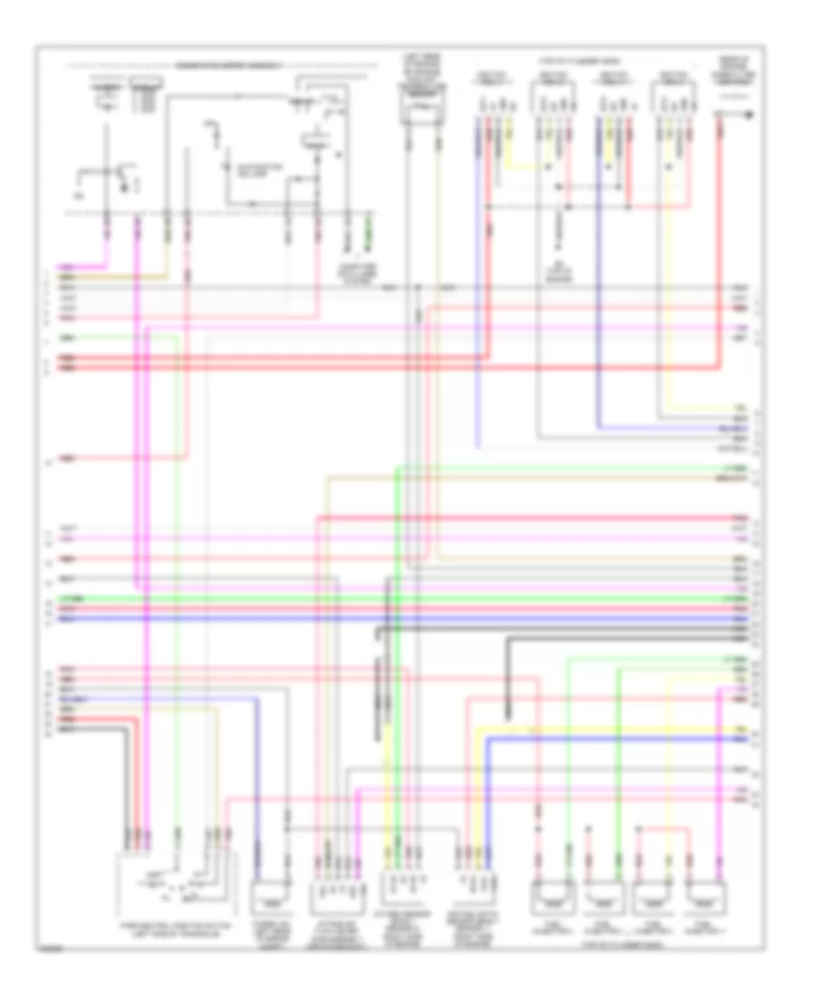
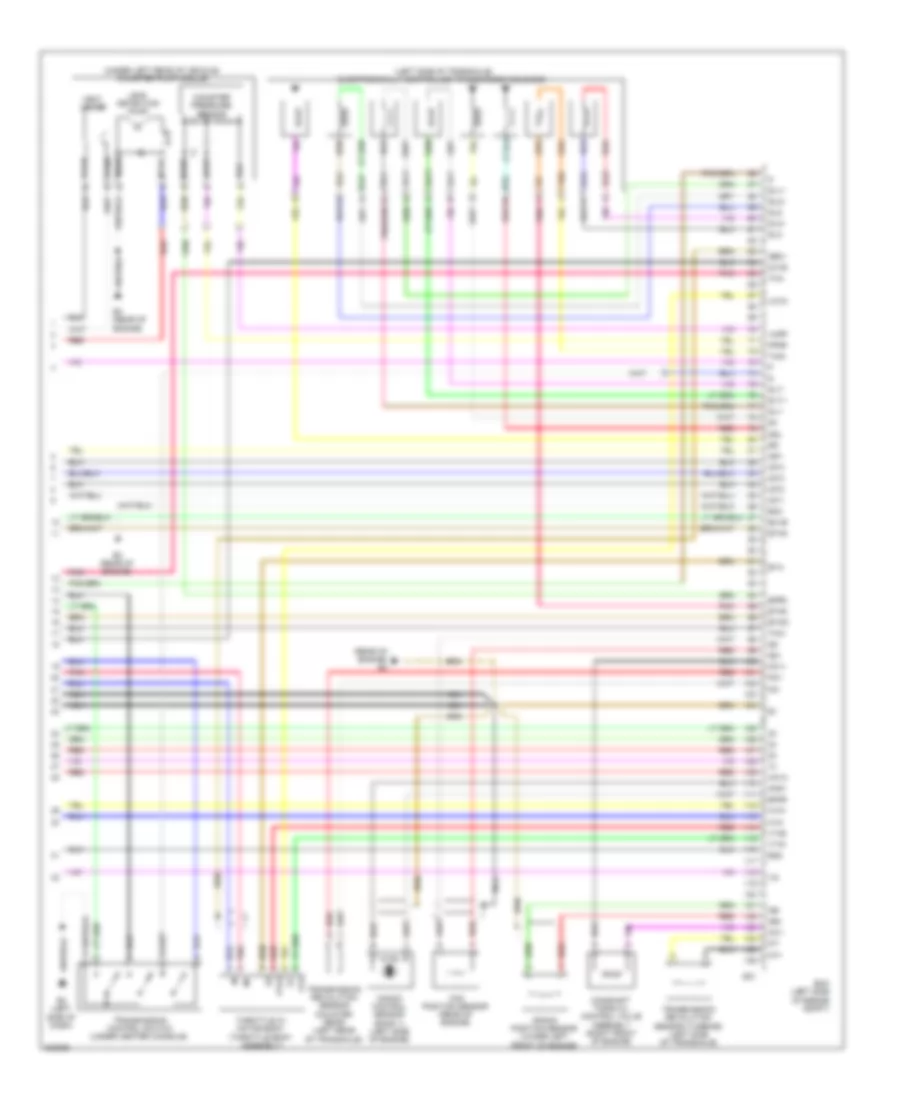
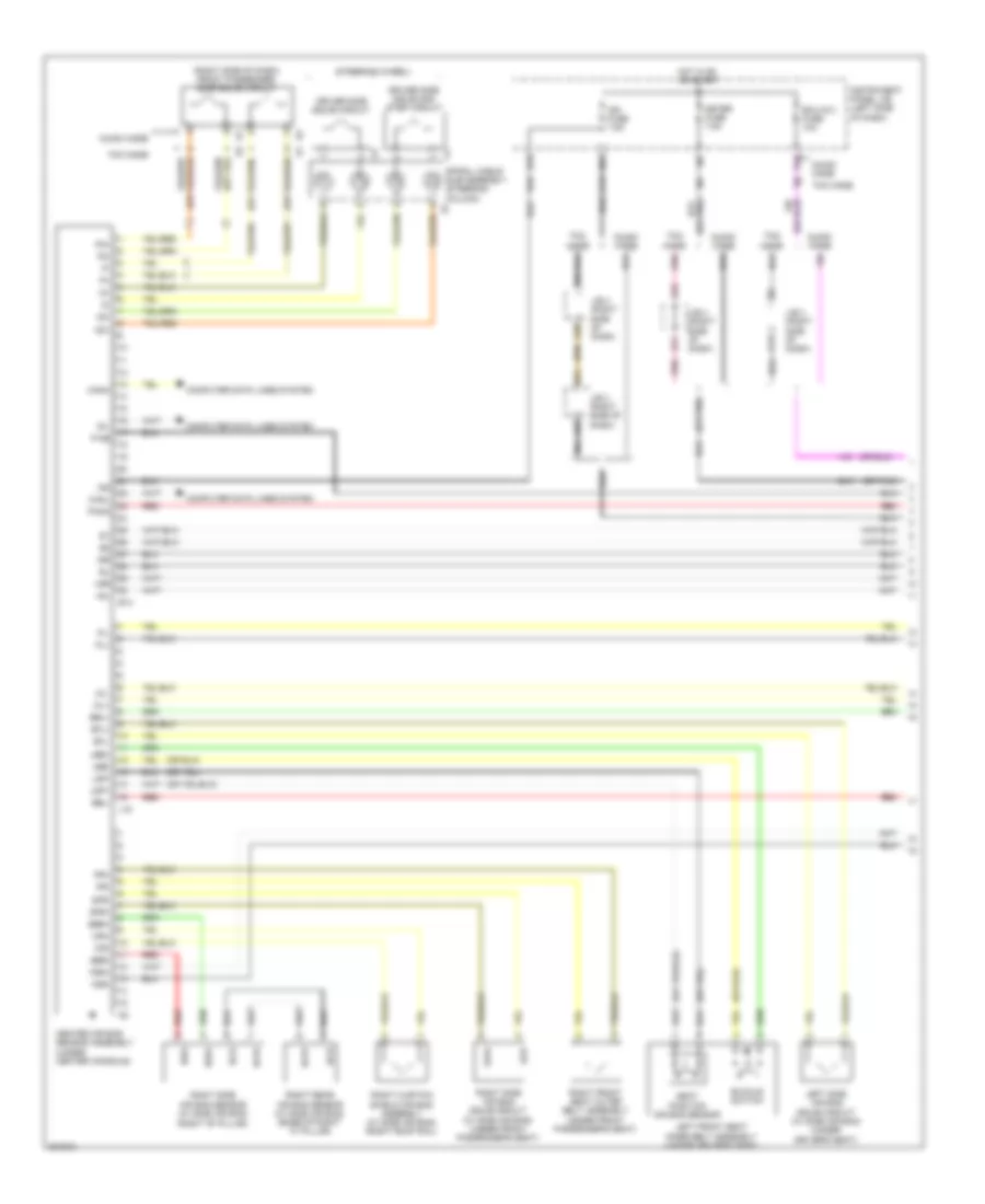
2.4L, Automatic A/C Wiring Diagram, NUMMI Made (1 of 3) for Toyota Corolla 2010
List of elements for 2.4L, Automatic A/C Wiring Diagram, NUMMI Made (1 of 3) for Toyota Corolla 2010:
- (left side of dash) e2
- A/c amplifier assembly (center of dash)
- A/c blower assembly (center of dash)
- A/c evaporator temperature sensor
- A/c pressure sensor (right front of engine compt)
- Alt
- B bus
- B25
- B3 (rear of engine)
- Blw
- Bus
- Bus g
- Canh
- Canl
- Computer data lines system
- Connector housing color (black)
- Connector housing color (red)
- Damper servo motor (air inlet)
- Damper servo motor (air mix)
- Damper servo motor (air vent mode)
- Daytime running light relay (right side of dash)
- Defogger system
- E2 (left side of dash)
- E30
- Ecu-b2 fuse 10a
- Ecu-ig 2 fuse 10a
- Engine room j/b (left side of engine compt)
- Engine room r/b (engine room j/b)
- Gnd
- H-lp
- H-lp relay
- Heater control sub-assembly
- Hls
- Hot at all times
- Hot in on or start
- Htr fuse 50a
- Htr-ig fuse 10a
- Ig+
- Ill+
- Ill-
- Instrument panel j/b (left side of dash)
- Interior lights system
- Lin1
- Pnk
- Pre
- Ptc1
- Ptc2
- Q10
- Rdfg
- Red
- S5-3
- S5-4
- Sg-1
- Sg-2
- Sga
- Short pin
- Sol+
- Sol-
- Starting/ charging system
- Tea
- W/ pulley compressor assembly (right front of engine compt)
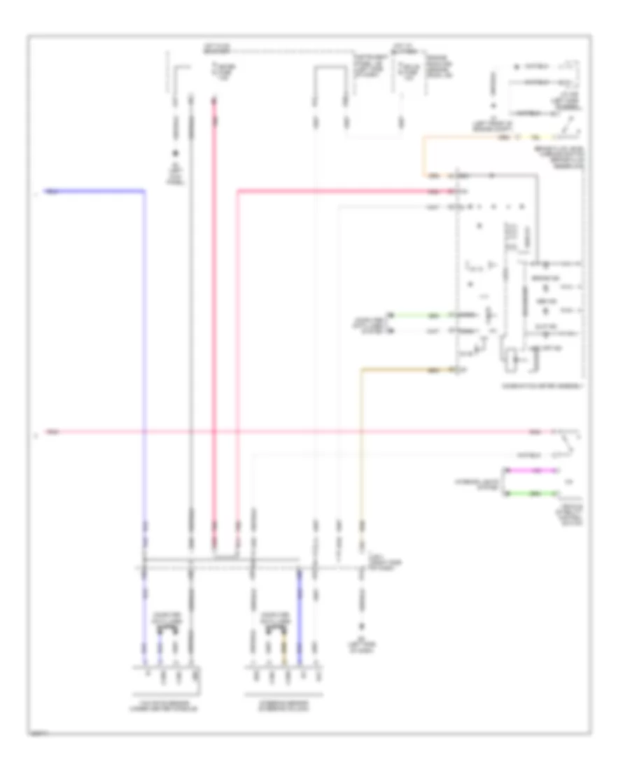
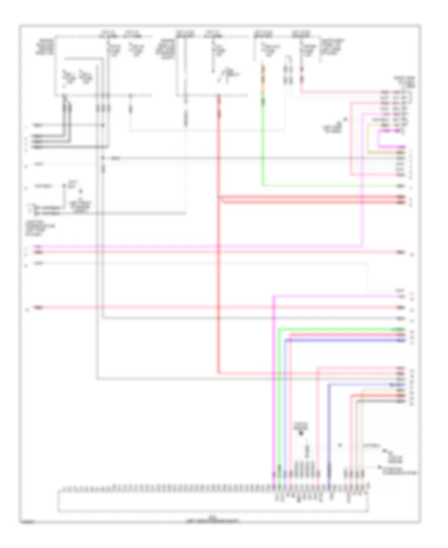
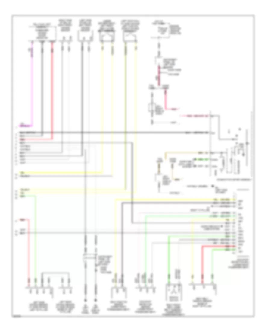
2.4L, Automatic A/C Wiring Diagram, NUMMI Made (2 of 3) for Toyota Corolla 2010
List of elements for 2.4L, Automatic A/C Wiring Diagram, NUMMI Made (2 of 3) for Toyota Corolla 2010:
- (left side of dash) e2
- (right end of dash) a6
- (right kick panel) e4
- 5v ic
- 5v+b
- A14
- A15
- A45
- Ambient temperature sensor (center front of engine compt)
- B24
- B30
- Blower w/ fan motor sub assembly (right side of dash)
- Can i/f
- Canh
- Canl
- Combination meter assembly
- Computer data lines system
- Cpu
- Ecu ig 1 fuse 10a
- Ecu-b fuse 10a
- Engine room r/b (engine room j/b)
- Gnd
- Hot at all times
- Hot in on or start
- Htr sub 1 fuse 30a
- Htr sub 3 fuse 30a
- Htr sub relay 1
- Htr sub relay 3
- I/f
- Ig+
- Instrument panel j/b (left side of dash)
- J/c a45 & a46 (left side of dash) a46
- Meter fuse 7.5a
- Quick heater assembly (right side of dash)
- R/b 7 (right side of engine compt)
- Red
- Room temperature sensor (center of dash)
- Solar sensor (right side of dash)
- Ss+
- Ss-
- Temp
- Tx1+
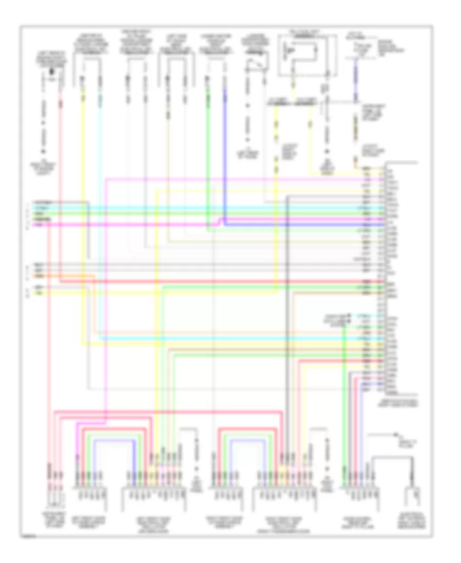
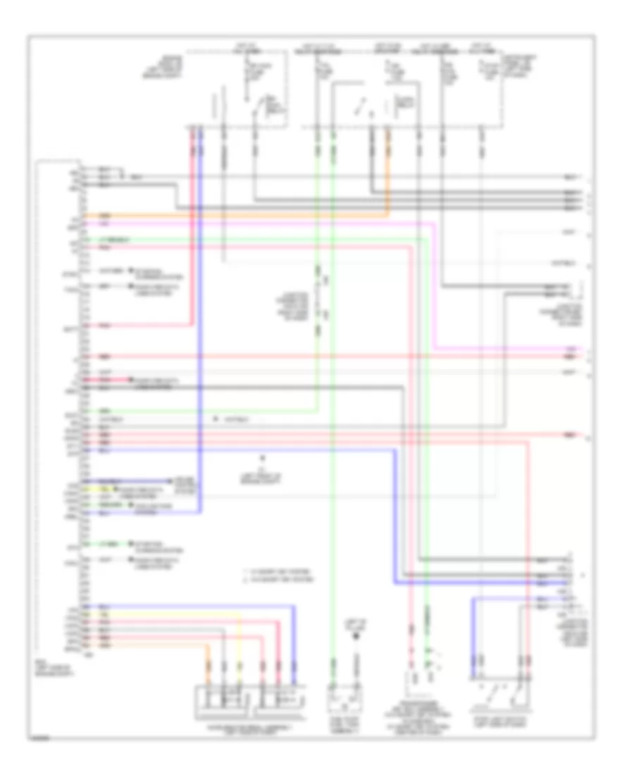
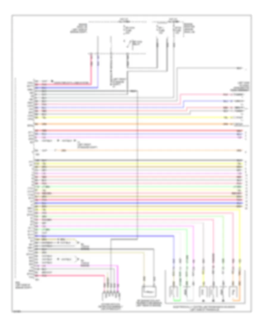
2.4L, Automatic A/C Wiring Diagram, NUMMI Made (3 of 3) for Toyota Corolla 2010
List of elements for 2.4L, Automatic A/C Wiring Diagram, NUMMI Made (3 of 3) for Toyota Corolla 2010:
- A1 (left front of engine compt)
- A50
- B31
- Canh
- Canl
- Cds fan fuse 30a
- Computer data lines system
- Cooling fan motor (behind radiator)
- Cooling fan motor 2 (behind radiator)
- Ecm (left side of engine compt)
- Efi engine coolant temperature sensor (rear of engine)
- Engine room j/b (left side of engine compt)
- Engine room r/b (engine room j/b)
- Ethw
- Fan relay 1
- Fan relay 2
- Fan relay 3
- Fanh
- Fanl
- Hot at all times
- Rdi fan fuse 40a
- Red
- Thw
2.4L, Manual A/C Wiring Diagram, NUMMI Made (1 of 2) for Toyota Corolla 2010
List of elements for 2.4L, Manual A/C Wiring Diagram, NUMMI Made (1 of 2) for Toyota Corolla 2010:
- (rear of engine) b3
- (right side of dash) blower w/ fan motor sub assembly
- (w/ ptc heater) h-lp relay
- A/c
- A/c amplifier assembly (center of dash)
- A/c pressure sensor (right front of engine compt)
- A/c switch
- A/c+
- A45
- Acid
- Aind
- Air inlet control switch
- Air mix damper servo sub assembly (right side of dash)
- Alt
- B24
- B25
- Blower resistor (right side of dash)
- Canh
- Canl
- Cds fan fuse 30a
- Computer data lines system
- Cooler thermistor 1 (center of dash)
- Def-logic
- E1 (left kick panel)
- E17
- E2 (left side of dash)
- E4 (right kick panel)
- E62
- E63
- Ecu-
- Ecu-b2 fuse 10a
- Ecu-ig 2 fuse 10a
- Engine room j/b (left side of engine compt)
- Engine room r/b (engine room j/b)
- F/d
- Free
- Frs
- Gnd
- H-lp main fuse 50a
- Head- lights system
- Heat
- Heater control base sub assembly
- Heater control sub assembly
- Heater control sub assembly 3
- Hls
- Hot at all times
- Hot w/ ig1 relay energized
- Htr fuse 50a
- Htr relay
- Htr-ig fuse 10a
- Ig 1 fuse 10a
- Ig+
- Ill+
- Ill-
- Instrument panel j/b (left side of dash)
- Interior lights system
- J/c a45 & a46 (left side of dash) a46
- Led
- Led+
- Lock
- Max hot switch
- Pnk
- Pre
- Ptc1
- Ptc2
- Q10
- Rdi fan fuse 40a
- Rec
- Red
- S5-3
- Sblw
- Sg-2
- Sg-3
- Sol+
- Sol-
- Starting/ charging system
- W/ ptc heater
- W/ pulley compressor assembly (right front of engine compt)
2.4L, Manual A/C Wiring Diagram, NUMMI Made (2 of 2) for Toyota Corolla 2010
List of elements for 2.4L, Manual A/C Wiring Diagram, NUMMI Made (2 of 2) for Toyota Corolla 2010:
- (right end of dash) a6
- A1 (left front of engine compt)
- A14
- A15
- A50
- A6 (right end of dash)
- B31
- Canh
- Canl
- Computer
- Cooling fan motor (behind radiator)
- Cooling fan motor 2 (behind radiator)
- Data lines
- Ecm (left side of engine compt)
- Efi engine coolant temperature sensor (rear of engine)
- Engine room r/b (engine room j/b)
- Ethw
- Fan relay 1
- Fan relay 2
- Fan relay 3
- Fanh
- Fanl
- Hot at all times
- Htr sub 1 fuse 30a
- Htr sub 1 relay (w/ ptc heater)
- Htr sub 3 fuse 30a
- Htr sub 3 relay (w/ ptc heater)
- Quick heater assembly (w/ ptc heater) (right side of dash)
- R/b 7 (right side of engine compt)
- Red
- System
- Thw
ANTI-LOCK BRAKES
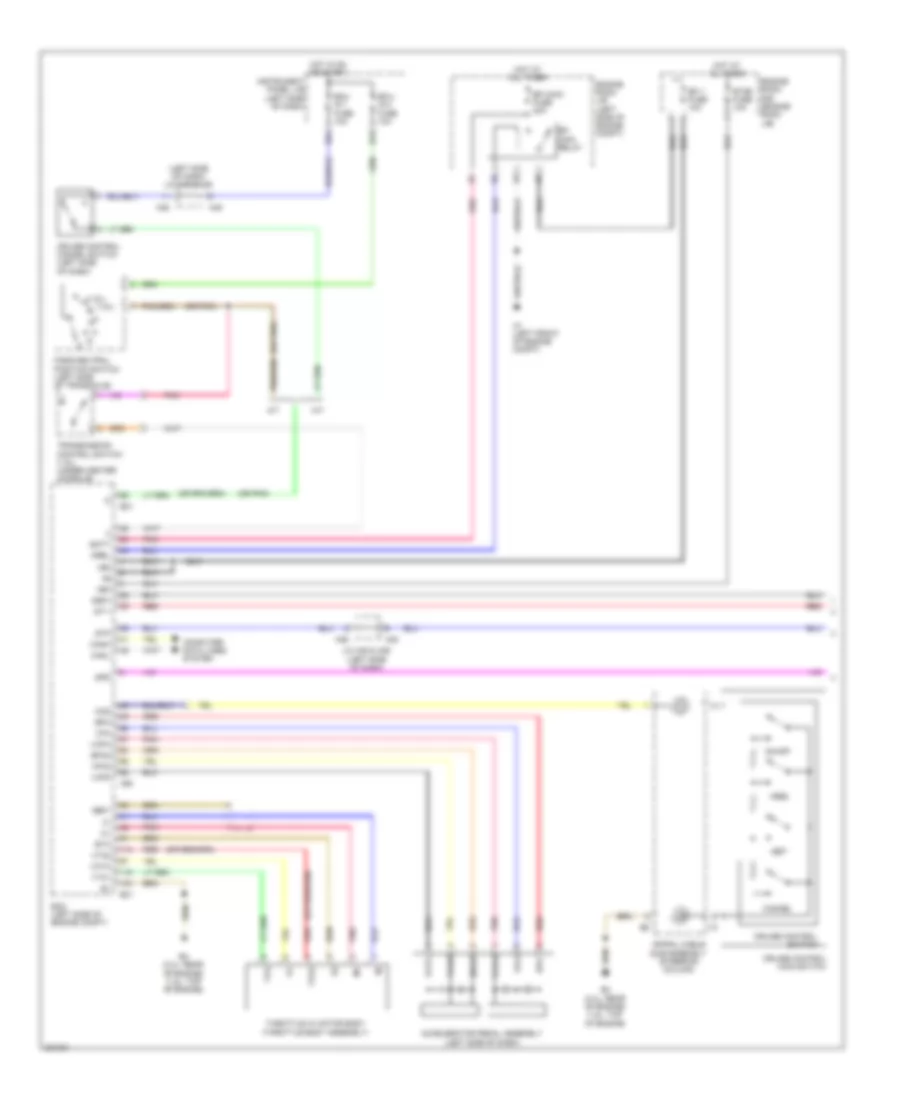
Anti-lock Brakes Wiring Diagram, NUMMI Made with VSC (1 of 2) for Toyota Corolla 2010
List of elements for Anti-lock Brakes Wiring Diagram, NUMMI Made with VSC (1 of 2) for Toyota Corolla 2010:
- (left side of dash) stop light switch
- (right front of engine compt) a4
- +bm
- +bs
- A4 (right front of engine compt)
- A50
- Abs 1 fuse 50a
- Abs 3 fuse 30a
- B12
- B18
- B19
- B21
- B24
- B31
- B4 (2.4l: rear of engine) (1.8l: top of engine)
- Brake actuator assembly (right front of engine compt)
- Canh
- Canl
- Computer data lines system
- Crank position sensor (lower left front of engine)
- Cruise control system
- Csw
- Dlc 3 (left side of dash)
- Ecm (left side of engine compt)
- Ecu-ig 1 fuse 10a
- Ecu-ig 2 fuse 10a
- Engine room j/b (left side of engine compt)
- Eta
- Fl+
- Fl-
- Fr+
- Fr-
- Ge01
- Gnd1
- Gnd2
- Hot at all times
- Hot in on or start
- Ig1
- Instrument panel j/b (left side of dash)
- J/c a45 (left side of dash)
- Left front speed sensor (left front wheel hub assembly)
- Left rear speed sensor (left rear wheel hub assembly)
- Ne+
- Ne-
- Park/neutral position switch (a/t) (left side of transaxle)
- Pnk
- Red
- Right front speed sensor (right front wheel hub assembly)
- Right rear speed sensor (right rear wheel hub assembly)
- Rl+
- Rl-
- Rr+
- Rr-
- Sp1
- Stop fuse 10a
- Stp
- Throttle w/ motor body (throttle body assembly)
- Vcta
- Vta
- Vta1
- Vta2
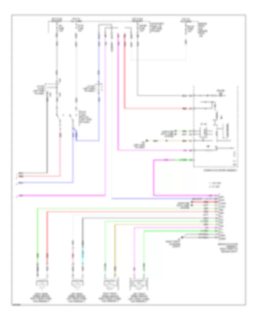
Anti-lock Brakes Wiring Diagram, NUMMI Made with VSC (2 of 2) for Toyota Corolla 2010
List of elements for Anti-lock Brakes Wiring Diagram, NUMMI Made with VSC (2 of 2) for Toyota Corolla 2010:
- 5v ic
- 5v+b
- A1 (left front of engine compt)
- Abs ind
- B30
- Bat
- Brake fluid level warning switch (brake master cylinder reservoir sub assembly) (brake fluid reservoir)
- Brake ind
- Buzzer
- Can i/f
- Canh
- Canl
- Combination meter assembly
- Computer data lines system
- Cpu
- E2 (left side of dash)
- Ecu-b fuse 10a
- Engine room r/b (engine room j/b)
- Ess
- Gnd
- H12
- Hot at all times
- Hot in on or start
- I/f
- Ig+
- Ig1
- Instrument panel j/b (left side of dash)
- Interior lights system
- J/c a46 (left side of dash)
- J/c e107 (right side of dash)
- Led driver
- Meter fuse 7.5a
- Red
- Slip ind
- Steering sensor (steering column)
- Vehicle stability control switch
- Vsc off ind
- Yaw rate sensor (under center console)
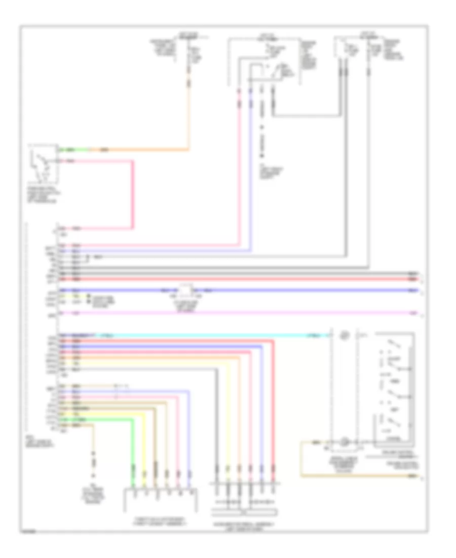
Anti-lock Brakes Wiring Diagram, NUMMI Made without VSC (1 of 2) for Toyota Corolla 2010
List of elements for Anti-lock Brakes Wiring Diagram, NUMMI Made without VSC (1 of 2) for Toyota Corolla 2010:
- +bm
- +bs
- A4 (right front of engine compt)
- Abs 1 fuse 50a
- Abs 3 fuse 30a
- B12
- B18
- B21
- B24
- Brake actuator assembly (right front of engine compt)
- Canh
- Canl
- Computer data lines system
- Cruise control system
- Dlc 3 (left side of dash)
- Ecu-ig 1 fuse 10a
- Engine room j/b (left side of engine compt)
- Fl+
- Fl-
- Fr+
- Fr-
- Gnd1
- Gnd2
- Hot at all times
- Hot in on or start
- Ig1
- Instrument panel j/b (left side of dash)
- J/c a45 (left side of dash)
- Left front speed sensor (left front wheel hub assembly)
- Left rear speed sensor (left rear wheel hub assembly)
- Pnk
- Red
- Right front speed sensor (right front wheel hub assembly)
- Right rear speed sensor (right rear wheel hub assembly)
- Rl+
- Rl-
- Rr+
- Rr-
- Sp1
- Stop fuse 10a
- Stop light switch assembly (left side of dash)
- Stp
- Throttle w/ motor body (throttle body assembly)
- Vta
- Vta2
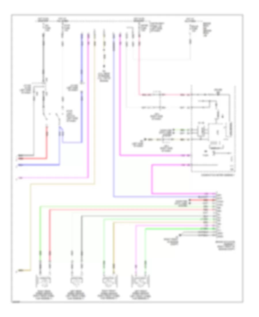
Anti-lock Brakes Wiring Diagram, NUMMI Made without VSC (2 of 2) for Toyota Corolla 2010
List of elements for Anti-lock Brakes Wiring Diagram, NUMMI Made without VSC (2 of 2) for Toyota Corolla 2010:
- 5v ic
- 5v+b
- A1 (left front of engine compt)
- A50
- Abs ind
- B19
- B30
- B31
- B4 (2.4l: rear of engine) (1.8l: top of engine)
- Brake fluid level warning switch (brake fluid reservoir)
- Brake ind
- Buzzer
- Can i/f
- Canh
- Canl
- Combination meter assembly
- Computer data lines system
- Cpu
- Crank position sensor (lower left front of engine)
- E2 (left side of dash)
- Ecm (left side of engine compt)
- Ecu-b fuse 10a
- Ecu-ig 2 fuse 10a
- Engine room r/b (engine room j/b)
- Eta
- Ge01
- Hot at all times
- Hot in on or start
- I/f
- Ig+
- Instrument panel j/b (left side of dash)
- J/c a46 (left side of dash)
- Led driver
- Meter fuse 7.5a
- Ne+
- Ne-
- Park/neutral position switch assembly (a/t) (left side of transaxle)
- Pnk
- Red
- Vcta
- Vta1
- Vta2
Anti-lock Brakes Wiring Diagram, TMC Made (1 of 2) for Toyota Corolla 2010
List of elements for Anti-lock Brakes Wiring Diagram, TMC Made (1 of 2) for Toyota Corolla 2010:
- (left side of dash) stop light switch
- (right front of engine compt) a4
- +bs
- A38
- A4 (right front of engine compt)
- A50
- Abs 1 fuse 50a
- Abs 3 fuse 30a
- B12
- B18
- B19
- B21
- B24
- B31
- B4 (rear of engine)
- Brake actuator assembly (right front of engine compt)
- Canh
- Canl
- Computer data lines system
- Crank position sensor (lower left front of engine)
- Cruise control system
- Csw
- Dlc 3 (left side of dash)
- Ecm (left side of engine compt)
- Ecu-ig 1 fuse 10a
- Ecu-ig 2 fuse 10a
- Engine room j/b (left side of engine compt)
- Eta
- Fl+
- Fl-
- Fr+
- Fr-
- Ge01
- Gnd1
- Gnd2
- Hot at all times
- Hot in on or start
- Ig1
- Instrument panel j/b (left side of dash)
- J/b 4 (right side of dash)
- J/c a45 (left side of dash)
- Left front speed sensor (left front wheel hub assembly)
- Left rear speed sensor (left rear wheel hub assembly)
- Ne+
- Ne-
- Park/neutral position switch (left side of transaxle)
- Pnk
- Red
- Right front speed sensor (right front wheel hub assembly)
- Right rear speed sensor (right rear wheel hub assembly)
- Rl+
- Rl-
- Rr+
- Rr-
- Sp1
- Stop fuse 10a
- Stp
- Throttle w/ motor body (throttle body assembly)
- Vcta
- Vta
- Vta1
- Vta2
Anti-lock Brakes Wiring Diagram, TMC Made (2 of 2) for Toyota Corolla 2010
List of elements for Anti-lock Brakes Wiring Diagram, TMC Made (2 of 2) for Toyota Corolla 2010:
- 5v ic
- 5v+b
- A1 (left front of engine compt)
- A26
- A28
- A29
- A30
- A34
- A37
- A42
- A52
- A70
- Abs ind
- B10
- B11
- B14
- B30
- Bat
- Brake fluid level warning switch (brake fluid reservoir)
- Brake ind
- Buzzer
- C11
- Can i/f
- Canh
- Canl
- Combination meter assembly
- Computer data lines system
- Cpu
- Display
- E1 (left kick panel)
- E17
- E2 (left side of dash)
- Ecu-b fuse 10a
- Engine room r/b (engine room j/b)
- Ess
- Gnd
- H12
- Hot at all times
- Hot in on or start
- I/f
- Ig+
- Ig1
- Instrument panel j/b (left side of dash)
- Interior lights system
- J/b 4 (right side of dash)
- J/c a46 (left side of dash)
- Led driver
- Meter fuse 7.5a
- Pnk
- Slip ind
- Steering sensor (steering column)
- Vehicle stability control switch
- Vsc off ind
- Yaw rate sensor (under center console)
ANTI-THEFT
Forced Entry Wiring Diagram, NUMMI Made with Smart Key System (1 of 3) for Toyota Corolla 2010
List of elements for Forced Entry Wiring Diagram, NUMMI Made with Smart Key System (1 of 3) for Toyota Corolla 2010:
- (left "b" pillar) l2
- (left kick panel) e1
- (right "b" pillar) m2
- (right kick panel) e4
- (right side of dash) j/c e107
- 5v ic
- 5v+b
- A21
- Acc
- Acc fuse 7.5a
- Act+
- Act-
- Actd
- Altb
- Am1
- Am2
- Am2 2 fuse 7.5a
- B30
- C12
- Can i/f
- Canh
- Canl
- Combination meter assembly
- Computer data lines system
- Cpu
- D14
- Dcty
- Dome fuse 10a
- Door fuse 25a
- E1 (left kick panel)
- E17
- E19
- E2 (left side of dash)
- E20
- E21
- E50
- E51
- E52
- E60
- Ecu-b fuse 10a
- Ecu-ig 1 fuse 10a
- Engine room r/b (engine room j/b)
- Gnd1
- Gnd2
- H12
- H13
- H14
- H17
- H18
- Hot at all times
- Hot in on or acc
- Hot in on or start
- Ign fuse 7.5a
- Inds
- Indw
- Instrument panel j/b (left side of dash)
- J/c e107 (right side of dash)
- Key lock
- Key unlk
- Lcty
- Led driver
- Left front door courtesy light switch assembly (left "b" pillar)
- Left front door lock assembly (driver's door)
- Left rear door courtesy light switch assembly (base of left "c" pillar)
- Left rear door lock assembly (left rear door)
- Lin1
- Lsr
- Lssr
- Lswd
- Lswp
- Main body ecu (instrument panel j/b)
- Pcty
- Pnk
- Rcty
- Red
- Right front door lock assembly (front passenger's door)
- Right rear door lock assembly (right rear door)
- Smart key ind
- Srx
- Ssw1
- Ssw2
- Stx
- Swil
- Ul1
- Ul3
- Unlk detection
Forced Entry Wiring Diagram, NUMMI Made with Smart Key System (2 of 3) for Toyota Corolla 2010
List of elements for Forced Entry Wiring Diagram, NUMMI Made with Smart Key System (2 of 3) for Toyota Corolla 2010:
- (right side of dash) j/c e107
- +b1
- 23e
- Agnd
- Antenna coil
- B30
- Brk+
- Brk-
- Clgb
- Code
- Com
- D12
- E1 (left kick panel)
- E17
- E2 (left side of dash)
- E4 (right kick panel)
- Engine switch
- Gb+b
- Gbig
- Gbs
- Gbsi
- Glass breakage sensor ecu assembly (right side of dash)
- Glass breakage sensor microphone (right side of dash)
- Gnd
- Inds
- Indw
- Instrument panel j/b (left side of dash)
- J/c e107 (right side of dash)
- Ksw
- Left front door lock control switch assembly
- Lock
- Mi+
- Mi-
- Mic+
- Mic-
- Power window
- Red
- Regulator master switch assembly
- Right front door courtesy light switch assembly (right "b" pillar)
- Right front door lock control switch assembly
- Right rear door courtesy light switch assembly (base of right "c" pillar)
- Ss1
- Ss2
- Swil
- Theft warning ecu assembly (right side of dash)
- Txct
- Un-lock warning switch (steering column)
- Unlock
- Vc5
- W/ power window
- W/o power window
Forced Entry Wiring Diagram, NUMMI Made with Smart Key System (3 of 3) for Toyota Corolla 2010
List of elements for Forced Entry Wiring Diagram, NUMMI Made with Smart Key System (3 of 3) for Toyota Corolla 2010:
- (center front of trunk) indoor luggage compartment electrical key oscillator
- (center of rear bumper) outside luggage electrical key antenna
- (left rear of engine compt) wireless door lock buzzer
- (left side of trunk) rear electrical key oscillator
- (under center console) front electrical key oscillator
- A3 (right front of engine compt)
- Acc
- Agnd
- Ant
- Ant1
- Ant2
- Asel
- B13
- B25
- Bzr
- Canh
- Canl
- Certification ecu (right side of dash)
- Cg1b
- Cg2b
- Cg5b
- Cg6b
- Cg7b
- Cg8b
- Clg
- Clg1
- Clg2
- Clg3
- Clg4
- Clg5
- Clg6
- Clg7
- Clg8
- Clgb
- Code
- Computer data lines system
- Data
- Door control receiver (right "c" pillar)
- E1 (left kick panel)
- E10
- E2 (left side of dash)
- E4 (right kick panel)
- Ecu-b2 fuse 10a
- Electrical key antenna (right side of rear bumper)
- Engine room r/b (engine room j/b)
- Gnd
- Hot at all times
- Ind
- Ind security
- Instrument panel j/b (left side of dash)
- J/c e107 (right side of dash)
- L3 (left rear of trunk)
- Left front door electrical key oscillator (driver's door)
- Left front door outside handle assembly
- Lin
- Luggage compartment door opener switch assembly
- M1 (right "c" pillar)
- Nca
- Pnk
- Rc0
- Rda
- Red
- Right front door electrical key oscillator (front passenger's door)
- Right front door outside handle assembly
- Rssi
- Sel
- Sel1
- Sel2
- Sen1
- Sen2
- Sens
- Sgt
- Telltale light assembly
- Trg+
- Trg-
- Tsw1
- Tsw2
- Tsw5
- Txct
- Vc5
- W/ theft deterrent
- W/o theft deterrent
Forced Entry Wiring Diagram, NUMMI Made without Smart Key System (1 of 2) for Toyota Corolla 2010
List of elements for Forced Entry Wiring Diagram, NUMMI Made without Smart Key System (1 of 2) for Toyota Corolla 2010:
- (base of left "c" pillar) left rear door courtesy light switch assembly
- (center rear of trunk lid) luggage compartment door lock assembly
- (right "c" pillar) m1
- (right front of engine compt) a3
- A21
- Acc
- Acc fuse 7.5a
- Act+
- Act-
- Actd
- Altb
- B13
- B28
- B30
- Becu
- Bzr
- Canh
- Canl
- Computer data lines system
- Courtesy
- Daytime running light relay (right side of dash)
- Dcty
- Detection unlk
- Dome fuse 10a
- Door control receiver (right "c" pillar)
- Door fuse 25a
- E1 (left kick panel)
- E17
- E19
- E2 (left side of dash)
- E20
- E23
- E4 (right kick panel)
- E50
- E51
- E61
- Ecu-b fuse 10a
- Ecu-ig 1 fuse 10a
- Ehw
- Engine room j/b (left side of engine compt)
- Engine room r/b (engine room j/b)
- Flasher relay
- Gnd
- Gnd1
- Gnd2
- H-lp
- H-lp relay
- H12
- H13
- H14
- H15
- H16
- H17
- H18
- Haz
- Horn
- Horn relay
- Hot at all times
- Hot in on or acc
- Hot in on or start
- Hrly
- Ile
- Instrument panel j/b (left side of dash)
- Interior lights system
- J/c e107 (right side of dash)
- Key lock
- Key unlk
- Ksw
- L3 (left rear of trunk)
- Lcty
- Left front door lock assembly (driver's door)
- Lgcv
- Lock key
- Lsr
- Lssr
- Lswd
- Lswp
- Main body ecu (instrument panel j/b)
- Pcty
- Pnk
- Prg
- Rcty
- Rda
- Red
- Right front door lock assembly (front passenger's door)
- Srx
- Stx
- Tr+
- Ul1
- Ul2
- Ul3
- Unlk detection
- Wireless door lock buzzer (left rear of engine compt)
Forced Entry Wiring Diagram, NUMMI Made without Smart Key System (2 of 2) for Toyota Corolla 2010
List of elements for Forced Entry Wiring Diagram, NUMMI Made without Smart Key System (2 of 2) for Toyota Corolla 2010:
- (base of right "c" pillar) right rear door courtesy light switch assembly
- (left "b" pillar)
- (left "b" pillar) l2
- (right "b" pillar) m2
- (right side of dash) j/c e107
- (steering column) un-lock warning switch
- +b1
- Brk+
- Brk-
- D12
- E1 (left kick panel)
- E17
- E2 (left side of dash)
- E23
- E4 (right kick panel)
- Gb+b
- Gbig
- Gbs
- Gbsi
- Glass breakage sensor ecu assembly (right side of dash)
- Glass breakage sensor microphone (right side of dash)
- Gnd
- Ind
- Instrument panel j/b (left side of dash)
- J/c e107 (right side of dash)
- Ksw
- Left front door courtesy light switch assembly
- Left front door lock control switch assembly
- Left rear door lock assembly (left rear door)
- Lock
- Lssr
- Mi+
- Mi-
- Mic+
- Mic-
- Power window regulator master switch assembly
- Red
- Right front door courtesy light switch assembly (right "b" pillar)
- Right front door lock control switch assembly
- Right rear door lock assembly (right rear door)
- Security ind
- Telltale light assembly
- Theft warning ecu assembly (right side of dash)
- Un-lock warning switch (steering column)
- Unlk detection
- Unlock
- W/ power window
- W/o power window
Forced Entry Wiring Diagram, TMC Made with Smart Key System (1 of 3) for Toyota Corolla 2010
List of elements for Forced Entry Wiring Diagram, TMC Made with Smart Key System (1 of 3) for Toyota Corolla 2010:
- (left "b" pillar) l2
- (left kick panel) e1
- (left side of dash) e2
- (right kick panel) e4
- (right side of dash) j/b 3
- 5v+b
- A11
- A21
- A40
- A74
- Acc
- Acc fuse 7.5a
- Act+
- Act-
- Actd
- Altb
- Am1
- Am2
- Am2 fuse 7.5a
- B10
- B14
- B22
- B30
- B58
- B65
- B71
- B76
- C11
- C12
- C15
- C23
- C57
- C58
- Can i/f
- Canh
- Canl
- Combination meter assembly
- Computer data lines system
- Cpu
- Dcty
- Dome fuse 10a
- Door fuse 25a
- E1 (left kick panel)
- E17
- E19
- E20
- E5 (center of dash)
- E50
- E51
- E52
- E56
- E57
- Ecu-b fuse 10a
- Ecu-ig 1 fuse 10a
- Engine room r/b (engine room j/b)
- Gnd1
- Gnd2
- H12
- H13
- H14
- H16
- H17
- H18
- Hot at all times
- Hot in on or acc
- Hot in on or start
- Ign fuse 7.5a
- Inds
- Indw
- Instrument panel j/b (left side of dash)
- J/b 3 (right side of dash)
- J/b 4 (right side of dash)
- J/c e56 & e57 (right side of dash)
- Key lock
- Key unlk
- Lcty
- Led driver
- Left front door lock assembly (driver's door)
- Left rear door courtesy light switch assembly (base of left "c" pillar)
- Left rear door lock assembly (left rear door)
- Lin1
- Lock key
- Lsr
- Lssr
- Lswd
- Lswp
- Main body ecu (instrument panel j/b)
- Pcty
- Pnk
- Rcty
- Red
- Right front door lock assembly (front passenger's door)
- Smart key ind
- Ssw1
- Ssw2
- Swil
- Ul1
- Ul2
- Ul3
- Unlk detection
Forced Entry Wiring Diagram, TMC Made with Smart Key System (2 of 3) for Toyota Corolla 2010
List of elements for Forced Entry Wiring Diagram, TMC Made with Smart Key System (2 of 3) for Toyota Corolla 2010:
- (right "b" pillar) m2
- A13
- A14
- A15
- A20
- A21
- A23
- A24
- A25
- A26
- A3 (right front of engine compt)
- A34
- A36
- A39
- A44
- A88
- A94
- Agnd
- Antenna coil
- B13
- B45
- B46
- B68
- B70
- B71
- C27
- C34
- Code
- E1 (left kick panel)
- E4 (right kick panel)
- E5 (center of dash)
- Engine switch
- Inds
- Indw
- Instrument panel j/b (left side of dash)
- J/b 3 (right side of dash)
- J/b 4 (right side of dash)
- Left front door courtesy light switch assembly (left "b" pillar)
- Lock
- Lssr
- Pnk
- Power window regulator master switch assembly
- Red
- Right front door courtesy light switch assembly (right "b" pillar)
- Right front door lock control switch assembly
- Right rear door courtesy light switch assembly (base of right "c" pillar)
- Right rear door lock assembly (right rear door)
- Ss1
- Ss2
- Swil
- Txct
- Unlk detection
- Unlock
- Vc5
- Wireless door lock buzzer (left rear of engine compt)
Forced Entry Wiring Diagram, TMC Made with Smart Key System (3 of 3) for Toyota Corolla 2010
List of elements for Forced Entry Wiring Diagram, TMC Made with Smart Key System (3 of 3) for Toyota Corolla 2010:
- (center front of trunk) indoor luggage compartment electrical key oscillator
- (center of rear bumper) outside luggage electrical key antenna
- (left side of trunk) rear electrical key oscillator
- (right side of dash) j/b 4
- (under center console) front electrical key oscillator
- A27
- A31
- A32
- A40
- A44
- A64
- Acc
- Agnd
- Ant
- Ant1
- Ant2
- Asel
- B14
- B25
- B69
- B75
- B80
- Bzr
- C40
- C42
- C53
- Canh
- Canl
- Certification ecu (right side of dash)
- Cg1b
- Cg2b
- Cg5b
- Cg6b
- Cg7b
- Cg8b
- Clg
- Clg1
- Clg2
- Clg3
- Clg4
- Clg5
- Clg6
- Clg7
- Clg8
- Clgb
- Code
- Computer data lines system
- Data
- Door control receiver (right "c" pillar)
- E1 (left kick panel)
- E10
- E2 (left side of dash)
- E4 (right kick panel)
- Ecu-b2 fuse 10a
- Electrical key antenna (right side of rear bumper)
- Engine room r/b (engine room j/b)
- Gnd
- Hot at all times
- Ind
- Ind security
- Instrument panel j/b (left side of dash)
- J/b 3 (right side of dash)
- J/b 4 (right side of dash)
- J/c l30 & l31 (left side of trunk)
- L3 (left rear of trunk)
- L30
- L31
- Left front door electrical key oscillator (driver's door)
- Left front door outside handle assembly
- Lin
- Luggage compartment door opener switch assembly
- M1 (right "c" pillar)
- Pnk
- Rc0
- Rda
- Red
- Right front door electrical key oscillator (front passenger's door)
- Right front door outside handle assembly
- Rssi
- Sel
- Sel1
- Sel2
- Sen1
- Sen2
- Sens
- Sgt
- Telltale light assembly
- Trg+
- Trg-
- Tsw1
- Tsw2
- Tsw5
- Txct
- Vc5
Forced Entry Wiring Diagram, TMC Made without Smart Key System (1 of 2) for Toyota Corolla 2010
List of elements for Forced Entry Wiring Diagram, TMC Made without Smart Key System (1 of 2) for Toyota Corolla 2010:
- (center rear of trunk lid) luggage compartment door lock assembly
- (left rear of trunk) l3
- (right "c" pillar) m1
- (right front of engine compt) a3
- A11
- A21
- A44
- A92
- Acc
- Acc fuse 7.5a
- Act+
- Act-
- Actd
- Altb
- B13
- B28
- B30
- B71
- Becu
- Bzr
- Canh
- Canl
- Computer data lines system
- Courtesy
- Daytime running light relay (right side of dash)
- Dcty
- Dome fuse 10a
- Door control receiver (right "c" pillar)
- Door fuse 25a
- E1 (left kick panel)
- E17
- E19
- E20
- E23
- E5 (center of dash)
- E50
- E51
- E56
- E57
- E61
- Ecu-b fuse 10a
- Ecu-ig 1 fuse 10a
- Ehw
- Engine room j/b (left side of engine compt)
- Engine room r/b (engine room j/b)
- Flasher relay
- Gnd
- Gnd1
- Gnd2
- H-lp
- H-lp relay
- H13
- H14
- H16
- H17
- H18
- Haz
- Horn
- Horn relay
- Hot at all times
- Hot in on or acc
- Hot in on or start
- Hrly
- Ile
- Instrument panel j/b (left side of dash)
- Interior lights system
- J/b 3 (right side of dash)
- J/b 4 (right side of dash)
- J/c e56 & e57 (right side of dash) e57
- J/c l30 & l31 (left side of trunk)
- Key lock
- Key unlk
- Ksw
- L30
- L31
- Lcty
- Left front door lock assembly (driver's door)
- Left rear door courtesy light switch assembly (base of left "c" pillar)
- Lgcv
- Lsr
- Lssr
- Lswd
- Lswp
- Main body ecu (instrument panel j/b)
- Pcty
- Pnk
- Prg
- Rcty
- Rda
- Red
- Tr+
- Ul1
- Ul2
- Ul3
- Unlk detection
- Wireless door lock buzzer (left rear of engine compt)
Forced Entry Wiring Diagram, TMC Made without Smart Key System (2 of 2) for Toyota Corolla 2010
List of elements for Forced Entry Wiring Diagram, TMC Made without Smart Key System (2 of 2) for Toyota Corolla 2010:
- (base of right "c" pillar) right rear door courtesy light switch assembly
- (left "b" pillar) l2
- (right "b" pillar) m2
- (right side of dash)
- (right side of dash) j/b 4
- A13
- A19
- A37
- A74
- A88
- A94
- C23
- C27
- C31
- C34
- C57
- Detection unlk
- E1 (left kick panel)
- E4 (right kick panel)
- E56
- E57
- J/b 3 (right side of dash)
- J/b 4
- J/b 4 (right side of dash)
- J/c e56 & e57 (right side of dash)
- Left front door courtesy light switch assembly (left "b" pillar)
- Left rear door lock assembly (left rear door)
- Lock
- Lock key
- Lssr
- Pnk
- Power window regulator master switch assembly
- Red
- Right front door courtesy light switch assembly (right "b" pillar)
- Right front door lock assembly (front passenger's door)
- Right front door lock control switch assembly
- Right rear door lock assembly (right rear door)
- Un-lock warning switch (steering column)
- Unlk detection
- Unlk key
- Unlock
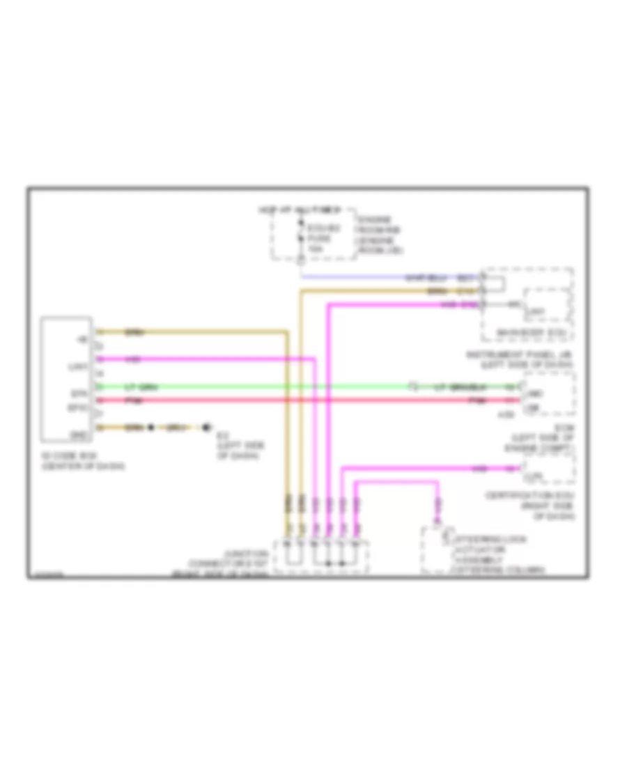
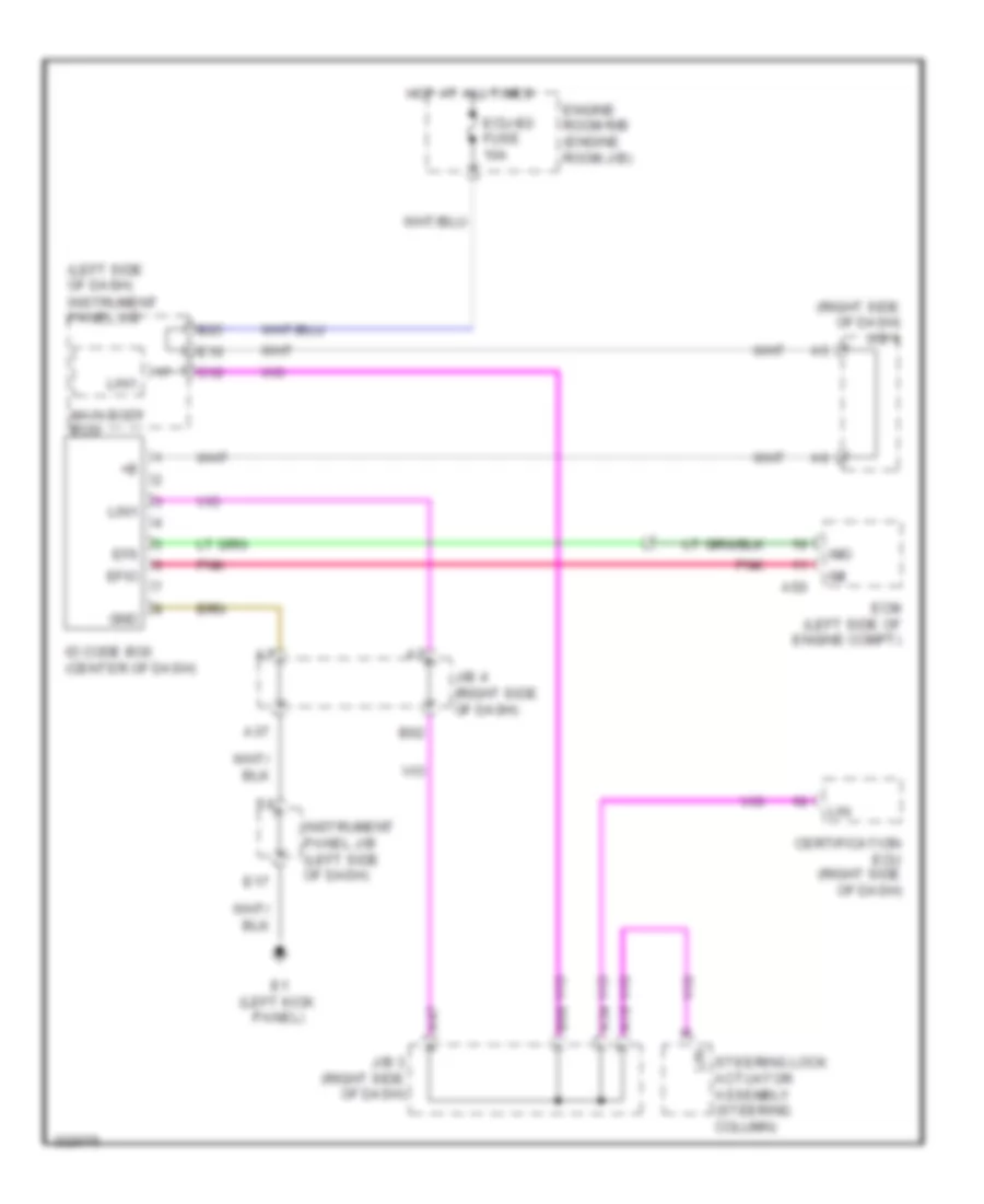
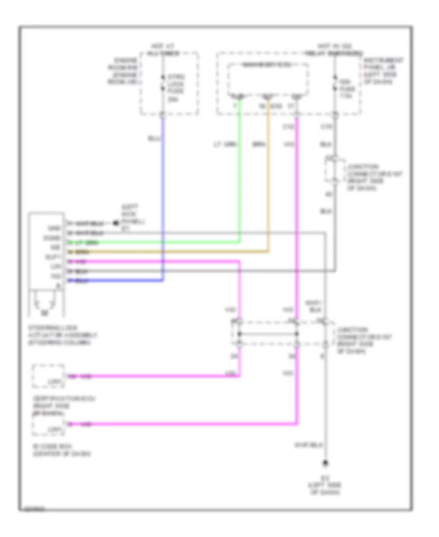
Immobilizer Wiring Diagram, NUMMI Made with Smart Key System for Toyota Corolla 2010
List of elements for Immobilizer Wiring Diagram, NUMMI Made with Smart Key System for Toyota Corolla 2010:
- A50
- B25
- C12
- Certification ecu (right side of dash)
- E10
- E2 (left side of dash)
- Ecm (left side of engine compt)
- Ecu-b2 fuse 10a
- Efii
- Efio
- Engine room r/b (engine room j/b)
- Gnd
- Hot at all times
- Id code box (center of dash)
- Imi
- Imo
- Instrument panel j/b (left side of dash)
- Junction connector e107 (right side of dash)
- Lin
- Lin1
- Main body ecu
- Pnk
- Steering lock actuator assembly (steering column)
Immobilizer Wiring Diagram, NUMMI Made without Smart Key System for Toyota Corolla 2010
List of elements for Immobilizer Wiring Diagram, NUMMI Made without Smart Key System for Toyota Corolla 2010:
- (left "b" pillar) left front door courtesy light switch assembly
- (left side of dash) instrument panel j/b
- A21
- A50
- Agnd
- Ant1
- Ant2
- B25
- Code
- Computer data lines system
- Cty
- E1 (left kick panel)
- E17
- E2 (left side of dash)
- E21
- E23
- E26
- Ecm (left side of engine compt)
- Ecu-b2 fuse 10a
- Efii
- Efio
- Engine room r/b (engine room j/b)
- Gnd
- Hot at all times
- Ign fuse 7.5a
- Imi
- Imo
- Ind
- Instrument panel j/b (left side of dash)
- Ksw
- Pnk
- Red
- Security ind
- Telltale light assembly
- Transponder key amplifier (steering column)
- Transponder key coil
- Transponder key ecu assembly (center of dash)
- Txct
- Unlock warning switch (steering column)
- Vc5
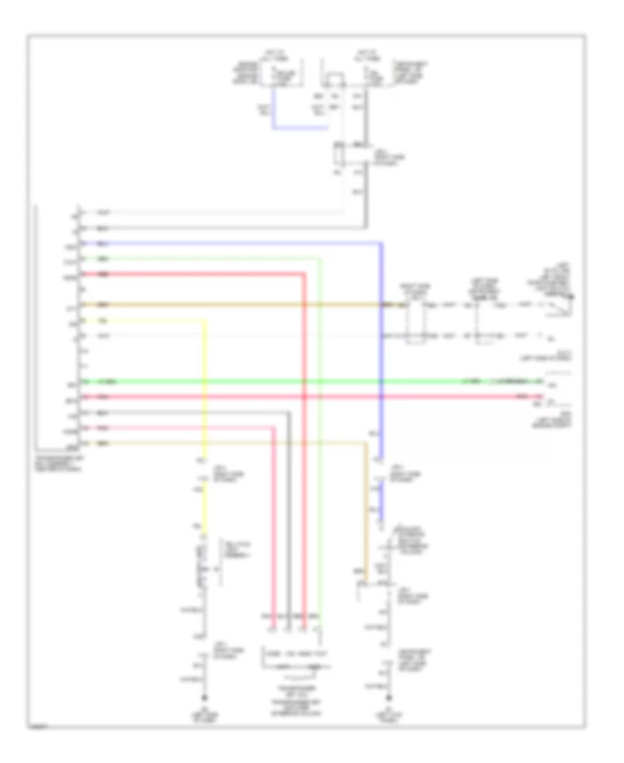
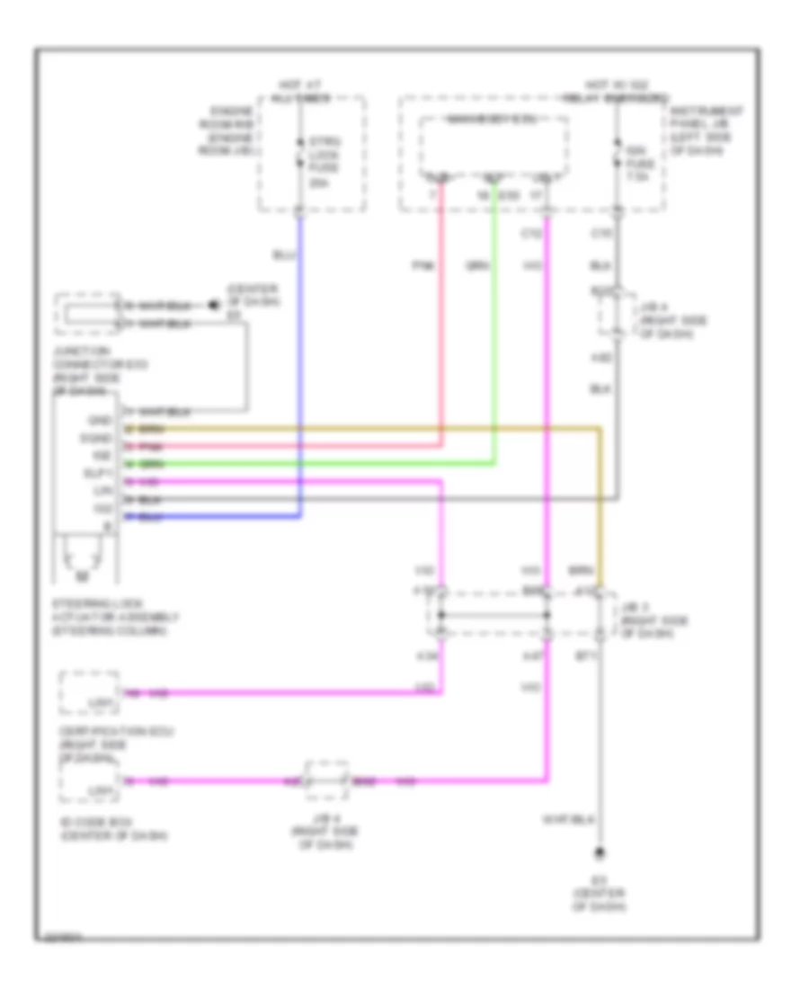
Immobilizer Wiring Diagram, TMC Made with Smart Key System for Toyota Corolla 2010
List of elements for Immobilizer Wiring Diagram, TMC Made with Smart Key System for Toyota Corolla 2010:
- (left side of dash) instrument panel j/b
- (right side of dash) j/b 4
- A10
- A34
- A37
- A47
- A50
- B25
- B62
- B68
- C12
- Certification ecu (right side of dash)
- E1 (left kick panel)
- E10
- E17
- Ecm (left side of engine compt)
- Ecu-b2 fuse 10a
- Efii
- Efio
- Engine room r/b (engine room j/b)
- Gnd
- Hot at all times
- Id code box (center of dash)
- Imi
- Imo
- Instrument panel j/b (left side of dash)
- J/b 3 (right side of dash)
- J/b 4 (right side of dash)
- Lin
- Lin1
- Main body ecu
- Pnk
- Steering lock actuator assembly (steering column)
Immobilizer Wiring Diagram, TMC Made without Smart Key System for Toyota Corolla 2010
List of elements for Immobilizer Wiring Diagram, TMC Made without Smart Key System for Toyota Corolla 2010:
- (left "b" pillar) left front door courtesy light switch assembly
- (left side of dash) instrument panel j/b
- (right side of dash)
- (right side of dash) j/b 4
- A10
- A11
- A13
- A19
- A21
- A37
- A50
- Agnd
- Ant1
- Ant2
- B14
- B21
- B22
- B25
- C15
- C35
- C40
- C42
- Code
- Cty
- Dlc 3 (left side of dash)
- E1 (left kick panel)
- E17
- E2 (left side of dash)
- Ecm (left side of engine compt)
- Ecu-b2 fuse 10a
- Efii
- Efio
- Engine room r/b (engine room j/b)
- Gnd
- Hot at all times
- Ign fuse 7.5a
- Imi
- Imo
- Ind
- Instrument panel j/b (left side of dash)
- J/b 4
- J/b 4 (right side of dash)
- Ksw
- Pnk
- Red
- Security ind
- Sil
- Telltale light assembly
- Transponder key amplifier (steering column)
- Transponder key coil
- Transponder key ecu assembly (center of dash)
- Txct
- Unlock warning switch (steering column)
- Vc5
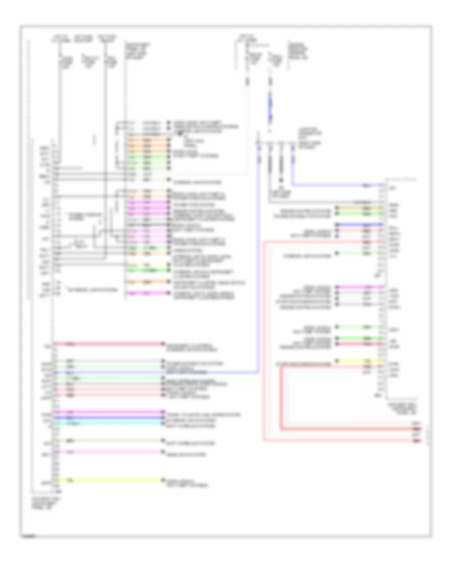
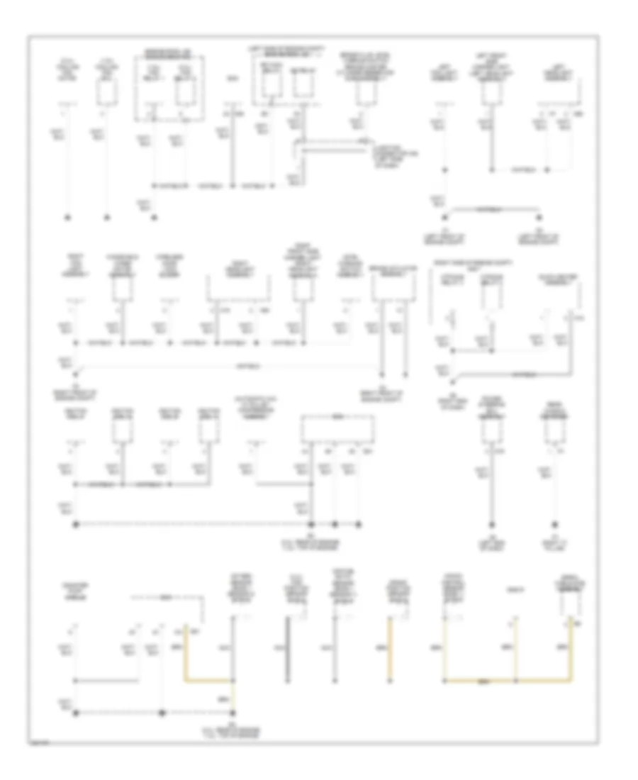
BODY CONTROL MODULES
Body Control Modules Wiring Diagram, NUMMI Made with Smart Key System (1 of 2) for Toyota Corolla 2010
List of elements for Body Control Modules Wiring Diagram, NUMMI Made with Smart Key System (1 of 2) for Toyota Corolla 2010:
- (right side of dash)
- A21
- Acc
- Acc fuse 7.5a
- Accd
- Accr
- Act+
- Act-
- Actd
- Altb
- Am1
- Am2
- Am2 2 fuse 7.5a
- B28
- B30
- Becu
- C12
- Canh
- Canl
- Cann
- Canp
- D14
- Dcty
- Door fuse 25a
- Door locks & anti-theft system
- Door locks & anti-theft system engine controls system
- Door locks & anti-theft systems
- Door locks, anti-theft & power windows systems
- Door locks, anti-theft, headlights & warning systems interior lights system
- E1 (left kick panel)
- E17
- E19
- E2 (left side of dash)
- E20
- E50
- E51
- E52
- Ecu ig 1 fuse 10a
- Ecu-b fuse 10a
- Engine controls system
- Engine controls system warning, audio, navigation & instrument cluster systems
- Engine room r/b (engine room j/b)
- Exterior lights system
- Gnd1
- Gnd2
- H13
- H14
- H17
- H18
- Haz
- Headlights system
- Horn
- Horns system
- Hot at all times
- Hot in on or acc
- Hot in on or start
- Hrly
- Ig1d
- Ig2d
- Ile
- Inds
- Indw
- Instrument cluster & interior lights systems
- Instrument cluster, headlights & navigation systems
- Instrument panel j/b (left side of dash)
- Interior lights & instrument cluster systems
- Interior lights system
- Interior lights, door locks & instrument cluster systems
- Interior lights, door locks, anti-theft & instrument cluster systems
- Junction connector e107
- Lcty
- Lgcy
- Lin1
- Lsr
- Lswd
- Lswp
- Main body ecu (instrument panel j/b)
- Pcty
- Pkb
- Pnk
- Power distribution system
- Power distribution system door locks & anti-theft systems
- Power tops system
- Power windows system
- Pws
- Rcty
- Red
- Shift interlock system
- Shift interlock system interior lights, door locks & anti-theft systems
- Slp
- Slr+
- Spd
- Ssw1
- Ssw2
- Starting/charging system
- Stp
- Str
- Str2
- Stsw
- Swil
- T-lp relay
- Tach
- Tcan
- Tlh
- Tr+
- Trly
- Trunk, tailgate, fuel doors system
- Ul1
- Ul3
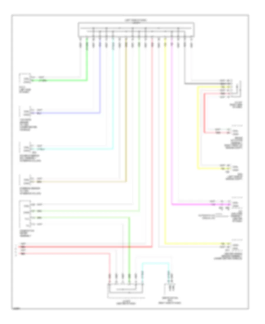
Body Control Modules Wiring Diagram, NUMMI Made with Smart Key System (2 of 2) for Toyota Corolla 2010
List of elements for Body Control Modules Wiring Diagram, NUMMI Made with Smart Key System (2 of 2) for Toyota Corolla 2010:
- (left side of dash) j/c e71
- A/c amplifier assembly (center of dash)
- A50
- Automatic a/c
- Brake actuator assembly (right front of engine compt)
- Canh
- Canl
- Center air bag sensor assembly (under center console)
- Certification ecu (right side of dash)
- Combination meter assembly
- Dlc 3 (left side of dash)
- E14
- E30
- E32
- E62
- Ecm (left side of engine compt)
- J/c a47 (right side of dash)
- J/c e72 (center of dash)
- Manual a/c
- Power steering ecu assembly (steering column)
- Red
- Steering sensor (w/ vsc) (steering column)
- Tx-
- Tx1-
- Yaw rate sensor (w/ vsc) (under center console)
Body Control Modules Wiring Diagram, NUMMI Made without Smart Key System for Toyota Corolla 2010
List of elements for Body Control Modules Wiring Diagram, NUMMI Made without Smart Key System for Toyota Corolla 2010:
- (left side of dash) j/c e71
- (right side of dash) j/c a47
- A/c amplifier assembly (center of dash)
- A21
- A50
- Acc
- Acc fuse 7.5a
- Act+
- Act-
- Actd
- Altb
- Anti-theft & instrument cluster systems
- Anti-theft system
- Automatic a/c
- B28
- B30
- Becu
- Brake actuator assembly (right front of engine compt)
- Bzr
- Canh
- Canl
- Center air bag sensor assembly (under center console)
- Combination meter assembly
- Dcty
- Dlc 3 (left side of dash)
- Door fuse 25a
- Door locks & anti-theft systems
- Door locks & anti-theft systems headlights system
- Door locks system & anti- theft systems
- Door locks, anti-theft & interior lights systems
- Door locks, anti-theft & power windows systems
- E1 (left kick panel)
- E14
- E17
- E19
- E20
- E23
- E30
- E32
- E62
- Ecm (left side of engine compt)
- Ecu ig 1 fuse 10a
- Ecu-b fuse 10a
- Engine controls system warning, audio, navigation & instrument cluster systems
- Engine room r/b (engine room j/b)
- Exterior lights system
- Gnd1
- H13
- H14
- H15
- H16
- H17
- H18
- Haz
- Headlights, door locks, anti-theft & warnings systems
- Horn
- Horns system
- Hot at all times
- Hot in on or acc
- Hot in on or start
- Hrly
- Ile
- Instrument cluster & interior lights systems
- Instrument cluster, navigation & headlights systems
- Instrument panel j/b (left side of dash)
- Interior lights system
- Interior lights system door locks, anti-theft & warning systems door locks, anti-theft & power windows systems
- Interior lights, door locks & instrument cluster systems
- Interior lights, door locks,
- Ksw
- Lcty
- Lgcy
- Lsr
- Lswd
- Lswp
- Main body ecu (instrument panel j/b)
- Manual a/c
- Pcty
- Pkb
- Pnk
- Power steering ecu assembly (steering column)
- Power tops system
- Power windows system
- Prg
- Pws
- Rcty
- Rda
- Red
- Spd
- Srx
- Steering sensor (w/ vsc) (steering column)
- Stx
- T-lp relay
- Trly
- Ul1
- Ul2
- Ul3
- Yaw rate sensor (w/ vsc) (under center console)
Body Control Modules Wiring Diagram, TMC Made with Smart Key System (1 of 2) for Toyota Corolla 2010
List of elements for Body Control Modules Wiring Diagram, TMC Made with Smart Key System (1 of 2) for Toyota Corolla 2010:
- A11
- A21
- Acc
- Acc fuse 7.5a
- Accd
- Accr
- Act+
- Act-
- Actd
- Altb
- Am1
- Am2
- Am2 2 fuse 7.5a
- B28
- B30
- B58
- B71
- Becu
- C12
- Canh
- Canl
- Cann
- Canp
- Dcty
- Door fuse 25a
- Door locks & anti-theft systems
- Door locks & anti-theft systems engine controls system
- Door locks, anti-theft & interior lights systems
- E1 (left kick panel)
- E17
- E19
- E20
- E5 (center of dash)
- E50
- E51
- E52
- Ecu ig 1 fuse 10a
- Ecu-b fuse 10a
- Engine controls system
- Engine room r/b (engine room j/b)
- Exterior lights system
- Gnd1
- Gnd2
- H13
- H14
- H16
- H17
- H18
- Haz
- Headlights system
- Horn
- Horns system door locks & anti-theft systems interior lights, door locks, anti-theft & instrument cluster systems
- Hot at all times
- Hot in on or acc
- Hot in on or start
- Hrly
- Ig1d
- Ig2d
- Ile
- Inds
- Indw
- Instrument cluster system
- Instrument panel j/b (left side of dash)
- Interior lights & instrument cluster systems
- Interior lights system
- Interior lights, door locks & anti-theft systems
- J/b 3 (right side of dash)
- Lcty
- Lgcy
- Lin1
- Lsr
- Lswd
- Lswp
- Main body ecu (instrument panel j/b)
- Pcty
- Pkb
- Pnk
- Power distribution system
- Power distribution system door locks & anti-theft systems
- Power windows system
- Pws
- Rcty
- Red
- Shift interlock system
- Slp
- Slr+
- Spd
- Ssw1
- Ssw2
- Starting/charging system
- Stp
- Str
- Str2
- Stsw
- Swil
- Tach
- Tcan
- Tlh
- Tr+
- Trly
- Trunk, tailgate, fuel doors system
- Ul1
- Ul2
- Ul3
Body Control Modules Wiring Diagram, TMC Made with Smart Key System (2 of 2) for Toyota Corolla 2010
List of elements for Body Control Modules Wiring Diagram, TMC Made with Smart Key System (2 of 2) for Toyota Corolla 2010:
- (center of dash) j/c e58
- A/c amplifier assembly (center of dash)
- A50
- Automatic a/c
- Brake actuator assembly (right front of engine compt)
- Canh
- Canl
- Center air bag sensor assembly (under center console)
- Certification ecu (right side of dash)
- Combination meter assembly
- Dlc 3 (left side of dash)
- E14
- E30
- E32
- E62
- Ecm (left side of engine compt)
- J/c a47 (right side of dash)
- J/c e59 (center of dash)
- Manual a/c
- Power steering ecu assembly (steering column)
- Red
- Steering sensor (steering column)
- Tx-
- Tx1-
- Yaw rate sensor (under center console)
Body Control Modules Wiring Diagram, TMC Made without Smart Key System for Toyota Corolla 2010
List of elements for Body Control Modules Wiring Diagram, TMC Made without Smart Key System for Toyota Corolla 2010:
- (center of dash) j/c e58
- (right side of dash) j/c a47
- A/c amplifier assembly (center of dash)
- A21
- A50
- Acc
- Acc fuse 7.5a
- Act+
- Act-
- Actd
- Altb
- Anti-theft & instrument cluster systems
- Automatic a/c
- B28
- B30
- Becu
- Brake actuator assembly (right front of engine compt)
- Bzr
- Canh
- Canl
- Center air bag sensor assembly (under center console)
- Combination meter assembly
- Dcty
- Dlc 3 (left side of dash)
- Door fuse 25a
- Door locks & anti-theft systems
- Door locks & anti-theft systems headlights system
- Door locks & anti-theft sytems
- Door locks system & anti- theft systems
- Door locks system instrument cluster & interior lights systems
- Door locks, anti-theft & headlights systems
- Door locks, anti-theft & interior lights systems
- Door locks, anti-theft & warning systems
- E1 (left kick panel)
- E14
- E17
- E19
- E20
- E23
- E30
- E32
- E62
- Ecm (left side of engine compt)
- Ecu ig 1 fuse 10a
- Ecu-b fuse 10a
- Engine room r/b (engine room j/b)
- Exterior lights system
- Gnd1
- H13
- H14
- H16
- H17
- H18
- Haz
- Horn
- Horns system
- Hot at all times
- Hot in on or acc
- Hot in on or start
- Hrly
- Ile
- Instrument cluster system
- Instrument panel j/b (left side of dash)
- Interior lights system
- Interior lights systems
- Interior lights, door locks & instrument cluster systems
- Interior lights, door locks/
- Ksw
- Lcty
- Lgcy
- Lsr
- Lswd
- Lswp
- Main body ecu (instrument panel j/b)
- Manual a/c
- Pcty
- Pkb
- Pnk
- Power steering ecu assembly (steering column)
- Power windows system
- Prg
- Pws
- Rcty
- Rda
- Red
- Spd
- Steering sensor (steering column)
- Ul1
- Ul2
- Ul3
- Yaw rate sensor (under center console)
COMPUTER DATA LINES
Computer Data Lines Wiring Diagram, NUMMI Made for Toyota Corolla 2010
List of elements for Computer Data Lines Wiring Diagram, NUMMI Made for Toyota Corolla 2010:
- (instrument panel j/b) main body ecu
- (left side of dash) j/c e71
- (right front of engine compt) brake actuator assembly
- (right side of dash) j/c a47
- A/c amplifier assembly (center of dash)
- A50
- Automatic a/c
- B23
- B4 (2.4l: rear of engine) (1.8l: top of engine)
- Bat
- Canh
- Canl
- Cann
- Canp
- Center air bag sensor assembly (under center console)
- Certification ecu (w/ smart key system) (right side of dash)
- Combination meter assembly
- Dia
- Dlc3 (left side of dash)
- E1 (left kick panel)
- E14
- E30
- E31
- E32
- E51
- E52
- E61
- E62
- Ecm (left side of engine compt)
- Hot at all times
- Instrument panel j/b (left side of dash)
- J/c e72 (w/ smart key system) (center of dash)
- Manual a/c
- Obd fuse 7.5a
- Occupant detection ecu (under front passenger's seat)
- Pnk
- Power steering ecu assembly (behind instrument cluster)
- Red
- Sil
- Steering sensor (w/ vsc) (steering column)
- Tac
- Tach
- Tire pressure warning ecu (center of dash)
- Transponder key ecu assembly (center of dash)
- Tx-
- Tx1-
- W/ smart key system
- W/o smart key system
- W/o vsc w/ vsc
- Yaw rate sensor (w/ vsc) (under center console)
Computer Data Lines Wiring Diagram, TMC Made for Toyota Corolla 2010
List of elements for Computer Data Lines Wiring Diagram, TMC Made for Toyota Corolla 2010:
- (center of dash) j/c e58
- (instrument panel j/b) main body ecu
- (right front of engine compt) brake actuator assembly
- (right side of dash) j/c a47
- A/c amplifier assembly (center of dash)
- A11
- A23
- A38
- A50
- A57
- Automatic a/c
- B19
- B23
- B31
- B4 (2.4l: rear of engine) (1.8l: top of engine)
- Bat
- C10
- C35
- Canh
- Canl
- Cann
- Canp
- Center air bag sensor assembly (under center console)
- Certification ecu (w/ smart key system) (right side of dash)
- Combination meter assembly
- Dia
- Dlc3 (left side of dash)
- E1 (left kick panel)
- E12
- E14
- E17
- E30
- E31
- E32
- E51
- E52
- E61
- E62
- Ecm (left side of engine compt)
- Hot at all times
- Instrument panel j/b (left side of dash)
- J/b 3 (right side of dash)
- J/b 4 (right side of dash)
- J/c e59 (w/ smart key system) (left side of dash)
- Manual a/c
- Obd fuse 7.5a
- Occupant detection ecu (under front passenger's seat)
- Pnk
- Power steering ecu assembly (behind instrument cluster)
- Red
- Sil
- Steering sensor (steering column)
- Tac
- Tach
- Tire pressure warning ecu (center of dash)
- Transponder key ecu assembly (center of dash)
- Tx-
- Tx1-
- W/ smart key system
- W/o smart key system
- Yaw rate sensor (under center console)
COOLING FAN
1.8L
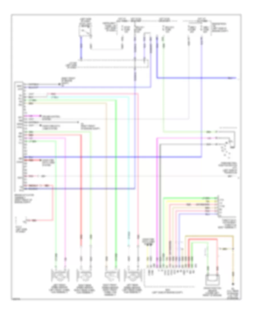
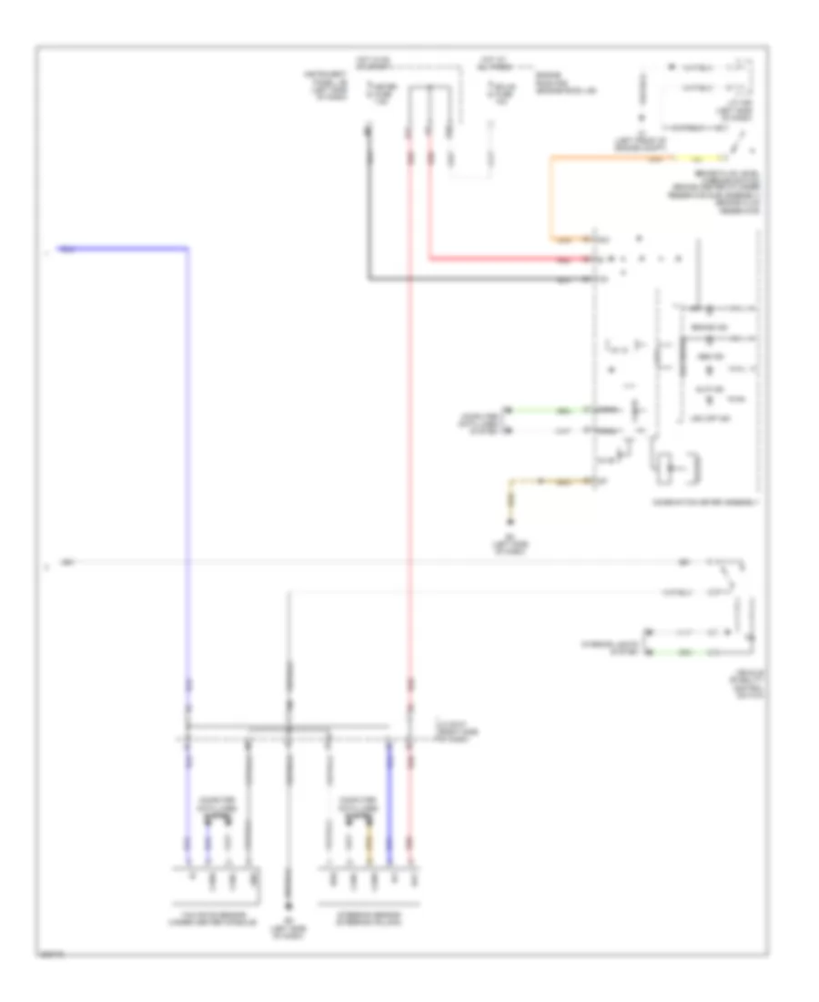
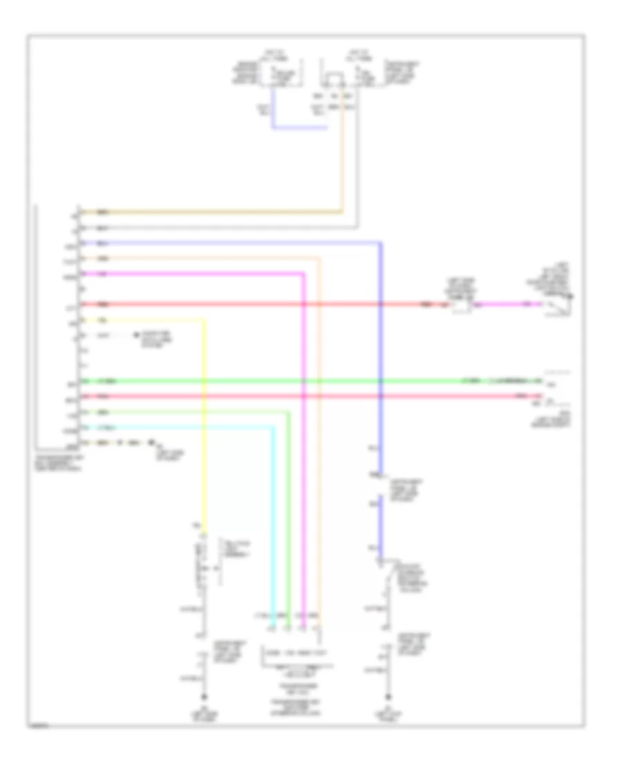
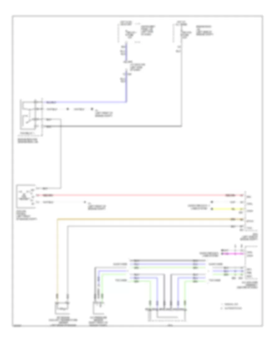
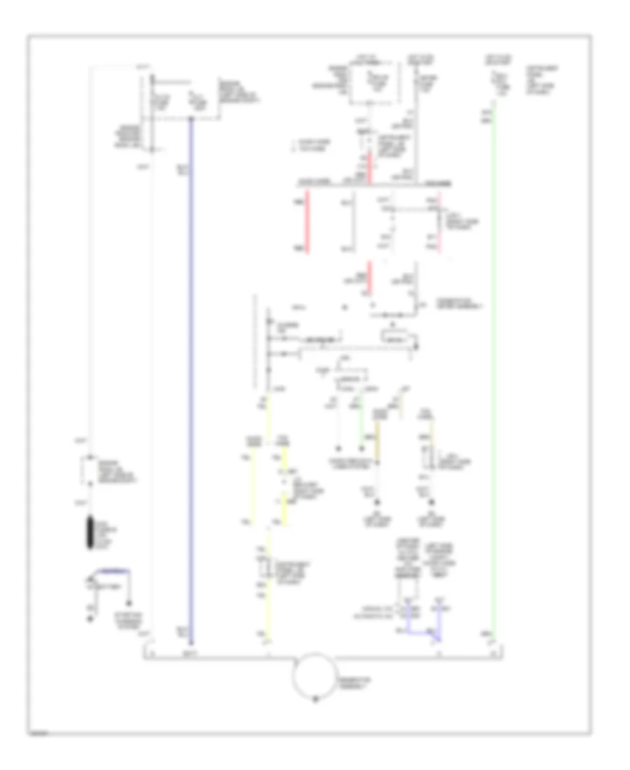
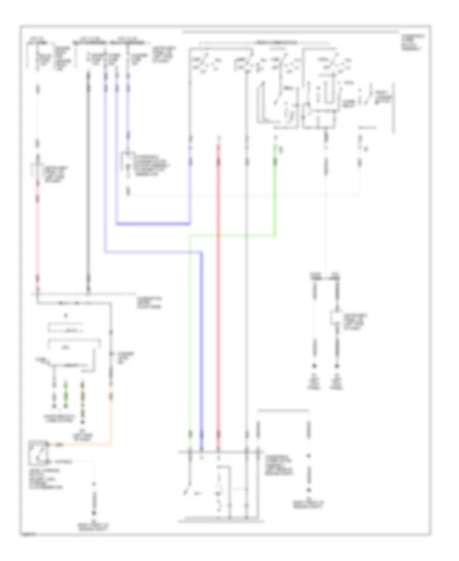
1.8L, Cooling Fan Wiring Diagram, NUMMI Made for Toyota Corolla 2010
List of elements for 1.8L, Cooling Fan Wiring Diagram, NUMMI Made for Toyota Corolla 2010:
- +b1
- A/c amplifier assembly (center of dash)
- A/c pressure sensor (right front of engine compt)
- A1 (left front of engine compt)
- A45
- A46
- A50
- Automatic a/c
- B24
- B31
- Canh
- Canl
- Computer data lines system
- Cooling fan ecu (left front of engine compt)
- E30
- E62
- Ecm (left side of engine compt)
- Ecu-ig 1 fuse 10a
- Efi engine coolant temperature sensor (left rear of engine)
- Engine room j/b (left side of engine compt)
- Engine room r/b (engine room j/b)
- Ethw
- Fan motor
- Fan relay 1
- Hot at all times
- Hot in on or start
- Instrument panel j/b (left side of dash)
- J/b 4
- J/c a45 & a46 (left side of dash)
- Manual a/c
- Nummi made
- Pre
- Rdi fan fuse 40a
- Rfc
- S5-3
- Sg-2
- Thw
- Tmc made
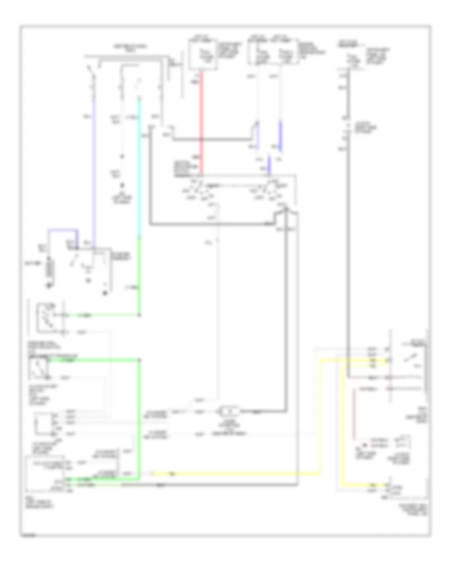
1.8L, Cooling Fan Wiring Diagram, TMC Made for Toyota Corolla 2010
List of elements for 1.8L, Cooling Fan Wiring Diagram, TMC Made for Toyota Corolla 2010:
- +b1
- A/c amplifier assembly (center of dash)
- A/c pressure sensor (right front of engine compt)
- A1 (left front of engine compt)
- A45
- A46
- A50
- Automatic a/c
- B24
- B31
- Canh
- Canl
- Computer data lines system
- Cooling fan ecu (left front of engine compt)
- E30
- E62
- Ecm (left side of engine compt)
- Ecu-ig 1 fuse 10a
- Efi engine coolant temperature sensor (left rear of engine)
- Engine room j/b (left side of engine compt)
- Engine room r/b (engine room j/b)
- Ethw
- Fan motor
- Fan relay 1
- Hot at all times
- Hot in on or start
- Instrument panel j/b (left side of dash)
- J/b 4
- J/c a45 & a46 (left side of dash)
- Manual a/c
- Nummi made
- Pre
- Rdi fan fuse 40a
- Rfc
- S5-3
- Sg-2
- Thw
- Tmc made
2.4L
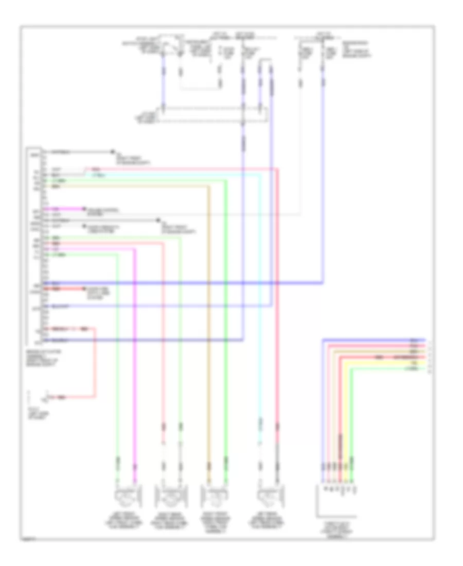
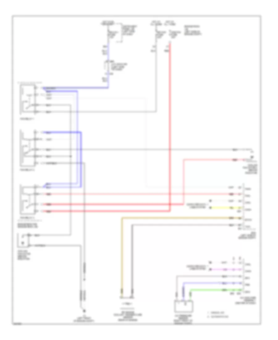
2.4L, Cooling Fan Wiring Diagram, NUMMI Made for Toyota Corolla 2010
List of elements for 2.4L, Cooling Fan Wiring Diagram, NUMMI Made for Toyota Corolla 2010:
- A/c amplifier assembly (center of dash)
- A/c pressure sensor (right front of engine compt)
- A1 (left front of engine compt)
- A45
- A46
- A50
- Automatic a/c
- B24
- B31
- Canh
- Canl
- Cds fan fuse 30a
- Computer data lines system
- Cooling fan motor (behind radiator)
- Cooling fan motor 2 (behind radiator)
- E30
- E62
- Ecm (left side of engine compt)
- Ecu-ig 1 fuse 10a
- Efi engine coolant temperature sensor (rear of engine)
- Engine room j/b (left side of engine compt)
- Engine room r/b (engine room j/b)
- Ethw
- Fan relay 1
- Fan relay 2
- Fan relay 3
- Fanh
- Fanl
- Hot at all times
- Hot in on or start
- Instrument panel j/b (left side of dash)
- J/c a45 & a46 (left side of dash)
- Manual a/c
- Pre
- Rdi fan fuse 40a
- Red
- S5-3
- Sg-2
- Thw
CRUISE CONTROL
Cruise Control Wiring Diagram, NUMMI Made (1 of 2) for Toyota Corolla 2010
List of elements for Cruise Control Wiring Diagram, NUMMI Made (1 of 2) for Toyota Corolla 2010:
- (1.8l)
- (left side of dash) j/c a45 & a46
- (or pnk)
- +b2
- +bm
- +res
- -set
- A/t
- A1 (left front of engine compt)
- A45
- A46
- A50
- Accelerator pedal assembly (left side of dash)
- B19
- B24
- B31
- B4 (2.4l: rear of engine) (1.8l: top of engine)
- Batt
- Cancel
- Canh
- Canl
- Ccs
- Computer data lines system
- Cruise control cancel switch (left side of dash)
- Cruise control main switch
- Cruise control switch
- Ecm (left side of engine compt)
- Ecu- ig 1 fuse 10a
- Ecu- ig 2 fuse 10a
- Efi 1 fuse 10a
- Efi main fuse 20a
- Efi main relay
- Engine room j/b (left side of engine compt)
- Engine room r/b (engine room j/b)
- Epa
- Epa2
- Eta
- Etcs fuse 10a
- Ge01
- Hot at all times
- Hot in on or start
- Igsw
- Instrument panel j/b (left side of dash)
- J/c a45 & a46 (left side of dash)
- M/t
- Mrel
- On-off
- Park/neutral position switch (left side of transaxle)
- Pnk
- Red
- Spd
- Spiral cable sub-assembly (steering column)
- St1-
- Stp
- Throttle w/ motor body (throttle body assembly)
- Transmission control switch (1.8l) (under center console)
- Vcp2
- Vcpa
- Vcta
- Vpa
- Vpa2
- Vta
- Vta1
- Vta2
Cruise Control Wiring Diagram, NUMMI Made (2 of 2) for Toyota Corolla 2010
List of elements for Cruise Control Wiring Diagram, NUMMI Made (2 of 2) for Toyota Corolla 2010:
- 5v +b
- 5v ic
- A4 (right front of engine compt)
- A45
- A46
- B12
- B18
- B21
- B30
- Brake actuator assembly (right front of engine compt)
- Can i/f
- Canh
- Canl
- Combination meter assembly
- Computer data lines system
- Cpu
- Cruise ind
- E2 (left side of dash)
- Ecu-b fuse 10a
- Engine room r/b (engine room j/b)
- Fl+
- Fl-
- Fr+
- Fr-
- Gnd1
- Gnd2
- Hot at all times
- Hot in on or start
- Ig2
- Ign fuse 7.5a
- Instrument panel j/b (left side of dash)
- J/c a45 & a46 (left side of dash)
- J/c a45 (left side of dash)
- Led driver
- Left front speed sensor (left front wheel hub assembly)
- Left rear speed sensor (left rear wheel hub assembly)
- Meter fuse 7.5a
- Pnk
- Red
- Right front speed sensor (right front wheel hub assembly)
- Right rear speed sensor (right rear wheel hub assembly)
- Rl+
- Rl-
- Rr+
- Rr-
- Sp1
- Stop fuse 10a
- Stop light switch (left side of dash)
- Stp
- W/ vsc
- W/o vsc
Cruise Control Wiring Diagram, TMC Made (1 of 2) for Toyota Corolla 2010
List of elements for Cruise Control Wiring Diagram, TMC Made (1 of 2) for Toyota Corolla 2010:
- +b2
- +bm
- +res
- -set
- A1 (left front of engine compt)
- A45
- A46
- A50
- Accelerator pedal assembly (left side of dash)
- B19
- B31
- B4 (2.4l: rear of engine) (1.8l: top of engine)
- Batt
- Cancel
- Canh
- Canl
- Ccs
- Computer data lines system
- Cruise control main switch
- Cruise control switch
- Ecm (left side of engine compt)
- Ecu- ig 2 fuse 10a
- Efi 1 fuse 10a
- Efi main fuse 20a
- Efi main relay
- Engine room j/b (left side of engine compt)
- Engine room r/b (engine room j/b)
- Epa
- Epa2
- Eta
- Etcs fuse 10a
- Ge01
- Hot at all times
- Hot in on or start
- Igsw
- Instrument panel j/b (left side of dash)
- J/c a45 & a46 (left side of dash)
- Mrel
- On-off
- Park/neutral position switch (left side of transaxle)
- Pnk
- Red
- Spd
- Spiral cable sub-assembly (steering column)
- St1-
- Stp
- Throttle w/ motor body (throttle body assembly)
- Vcp2
- Vcpa
- Vcta
- Vpa
- Vpa2
- Vta
- Vta1
- Vta2
Cruise Control Wiring Diagram, TMC Made (2 of 2) for Toyota Corolla 2010
List of elements for Cruise Control Wiring Diagram, TMC Made (2 of 2) for Toyota Corolla 2010:
- 5v +b
- 5v ic
- A20
- A4 (right front of engine compt)
- A45
- A46
- A70
- B10
- B11
- B12
- B14
- B18
- B21
- B30
- B4 (2.4l: rear of engine) (1.8l: top of engine)
- Brake actuator assembly (right front of engine compt)
- C11
- C14
- Can i/f
- Canh
- Canl
- Combination meter assembly
- Computer data lines system
- Cpu
- Cruise ind
- Display
- E2 (left side of dash)
- Ecu-b fuse 10a
- Engine room r/b (engine room j/b)
- Fl+
- Fl-
- Fr+
- Fr-
- Gnd1
- Gnd2
- H12
- Hot at all times
- Hot in on or start
- Ig2
- Ign fuse 7.5a
- Instrument panel j/b (left side of dash)
- J/b 4 (right side of dash)
- J/c a45 & a46 (left side of dash)
- J/c a45 (left side of dash)
- Led driver
- Left front speed sensor (left front wheel hub assembly)
- Left rear speed sensor (left rear wheel hub assembly)
- Meter fuse 7.5a
- Pnk
- Red
- Right front speed sensor (right front wheel hub assembly)
- Right rear speed sensor (right rear wheel hub assembly)
- Rl+
- Rl-
- Rr+
- Rr-
- Sp1
- Stop fuse 10a
- Stop light switch (left side of dash)
- Stp
DEFOGGERS
Defoggers Wiring Diagram, NUMMI Made for Toyota Corolla 2010
List of elements for Defoggers Wiring Diagram, NUMMI Made for Toyota Corolla 2010:
- A/c amplifier assembly (center of dash)
- Automatic a/c
- Def fuse 40a
- Def relay
- Def+
- Defb
- E1 (left kick panel)
- E2 (left side of dash)
- E30
- E4 (right kick panel)
- Ecu-ig 2 fuse 10a
- Gnd
- Heater control sub-assembly
- Hot at all times
- Hot in on or start
- Htr-ig fuse 10a
- Ig+
- Instrument panel j/b (left side of dash)
- Interior lights system
- L46
- Left outer rear view mirror assembly (left mirror)
- M11
- Manual a/c
- Mir htr fuse 10a
- Mirror heater
- Noise filter (rear window defogger) (left "c" pillar)
- P1 (right "c" pillar)
- Q10
- Q12
- Rdef
- Rdfg
- Rear window defogger
- Rear window defogger switch
- Red
- Right outer rear view mirror assembly (right mirror)
Defoggers Wiring Diagram, TMC Made for Toyota Corolla 2010
List of elements for Defoggers Wiring Diagram, TMC Made for Toyota Corolla 2010:
- A/c amplifier assembly (center of dash)
- Automatic a/c
- B14
- B16
- B19
- B28
- B32
- B38
- B45
- C26
- Def fuse 40a
- Def relay
- E1 (left kick panel)
- E17
- E18
- E2 (left side of dash)
- E30
- E4 (right kick panel)
- E56
- E57
- Ecu-ig 2 fuse 10a
- Gnd
- Heater control sub-assembly
- Hot at all times
- Hot in on or start
- Htr-ig fuse 10a
- Ig+
- Instrument panel j/b (left side of dash)
- Interior lights system
- J/b 4 (right side of dash)
- J/c e56 & e57 (right side of dash)
- L46
- Left outer rear view mirror assembly (left mirror)
- M11
- Manual a/c
- Mir htr fuse 10a
- Mirror heater
- Noise filter (rear window defogger) (left "c" pillar)
- P1 (right "c" pillar)
- Q10
- Q12
- Rdef
- Rdfg
- Rear window defogger
- Rear window defogger switch
- Right outer rear view mirror assembly (right mirror)
ELECTRONIC POWER STEERING
Electronic Power Steering Wiring Diagram, NUMMI Made for Toyota Corolla 2010
List of elements for Electronic Power Steering Wiring Diagram, NUMMI Made for Toyota Corolla 2010:
- (left end of dash) a5
- 5v +b
- 5v ic
- A75
- B30
- Can i/f
- Canh
- Canl
- Combination meter assembly
- Computer data lines system
- Cpu
- Cruise control system
- E2 (left side of dash)
- E32
- Ecu- ig1 fuse 10a
- Ecu-b fuse 10a
- Engine room j/b (left side of engine compt)
- Engine room r/b (engine room j/b)
- Eps fuse 60a
- Hot at all times
- Hot w/ ig1 relay energized
- Hot w/ ig2 relay energized
- Ig2
- Instrument panel j/b (left side of dash)
- Led driver
- Meter fuse 7.5a
- P/s ind
- Pgnd
- Pig
- Power steering ecu assembly (behind instrument cluster)
- Power steering motor
- Power steering torque sensor
- Red
- Resolver motor
- Rzcs
- Rzg
- Rzsn
- Rzv
- Steering column assembly
- Steering column assembly (1.8l)
- Steering column assembly (2.4l)
- Trq1
- Trq2
- Trqg
- Trqv
Electronic Power Steering Wiring Diagram, TMC Made for Toyota Corolla 2010
List of elements for Electronic Power Steering Wiring Diagram, TMC Made for Toyota Corolla 2010:
- (left end of dash) a5
- (right side of dash)
- 5v +b
- 5v ic
- A42
- A54
- A70
- B10
- B11
- B14
- B30
- C11
- Can i/f
- Canh
- Canl
- Combination meter assembly
- Computer data lines system
- Cpu
- Display
- E2 (left side of dash)
- E32
- Ecu- ig1 fuse 10a
- Ecu-b fuse 10a
- Engine room j/b (left side of engine compt)
- Engine room r/b (engine room j/b)
- Eps fuse 60a
- H12
- Hot at all times
- Hot w/ ig1 relay energized
- Hot w/ ig2 relay energized
- Instrument panel j/b (left side of dash)
- J/b 4
- J/b 4 (right side of dash)
- Led driver
- Meter fuse 7.5a
- P/s ind
- Pgnd a75
- Pig
- Pnk
- Power steering ecu assembly (behind instrument cluster)
- Power steering motor
- Power steering torque sensor
- Steering column assembly
- Trq1
- Trq2
- Trqg
- Trqv
ENGINE PERFORMANCE
1.8L
1.8L, Engine Performance Wiring Diagram, NUMMI Made (1 of 5) for Toyota Corolla 2010
List of elements for 1.8L, Engine Performance Wiring Diagram, NUMMI Made (1 of 5) for Toyota Corolla 2010:
- (left ''b'' pillar) l2
- +b2
- +bm
- A1 (left front of engine compt)
- A45
- A46
- A48
- A49
- A50
- Accelerator pedal assembly (left side of dash)
- Accr
- Anti-theft system
- B10
- B11
- B15
- B18
- Batt
- C/opn relay
- Canh
- Canl
- Ccs
- Computer data lines system
- Cooling fans system
- Cruise control system
- Ecm (left side of engine compt)
- Efi main fuse 20a
- Efi main relay
- Els1
- Els2
- Engine room j/b (left side of engine compt)
- Epa
- Epa2
- Fuel pump
- Fuel pump (fuel tank assembly) fuel sender gage assembly (top of fuel tank)
- Hot at all times
- Hot in on or start
- Hot w/ def relay energized
- Hot w/ t-lp relay energized
- Ig2 fuse 15a
- Ig2 relay
- Ign fuse 7.5a
- Igsw
- Imi
- Imo
- Instrument cluster system
- Instrument panel j/b (left side of dash)
- J/c a45 & a46 (left side of dash)
- J/c a46 (left side of dash)
- J/c a48 & a49 (right side of dash)
- M11
- Mir htr fuse 10a
- Mpmp
- Mrel
- Pnk
- Red
- Rfc
- Spd
- St1-
- Sta
- Starting/ charging system
- Stop fuse 10a
- Stop light switch (left side of dash)
- Stp
- Stsw
- Tach
- Tail fuse 10a
- Vcp2
- Vcpa
- Vpa
- Vpa2
- Vpmp
1.8L, Engine Performance Wiring Diagram, NUMMI Made (2 of 5) for Toyota Corolla 2010
List of elements for 1.8L, Engine Performance Wiring Diagram, NUMMI Made (2 of 5) for Toyota Corolla 2010:
- (instrument panel j/b) main body ecu
- (right side of dash) j/c e107
- A/t
- A45
- A46
- Acc
- Acc cut relay (w/o smart key system)
- Acc relay
- Accr
- Am2
- Am2 2 fuse 7.5a
- B3 (top of engine)
- B31
- B4 (top of engine)
- Backup light switch (transaxle assembly)
- Clutch start switch (left side of dash)
- E50
- E51
- E52
- Ecm (left side of engine compt)
- Ecu-b fuse 10a
- Efi 1 fuse 10a
- Efi 2 fuse 10a
- Engine room r/b (engine room j/b)
- Eo1
- Eo2
- Eo4
- Etcs fuse 10a
- Hot at all times
- Hot in on or acc
- Ht1b
- Ig2
- Ig2d
- Ignition or starter switch assembly
- J/c a45 & a46 (left side of dash)
- Lock off
- M/t
- Meo1
- Pnk
- Prg
- Red
- Slt+
- Slt-
- Star
- Start
- Starting/ charging system
- Starting/charging system
- W/ smart key system
- W/o smart key system
1.8L, Engine Performance Wiring Diagram, NUMMI Made (3 of 5) for Toyota Corolla 2010
List of elements for 1.8L, Engine Performance Wiring Diagram, NUMMI Made (3 of 5) for Toyota Corolla 2010:
- 5v +b
- 5v ic
- A/t
- A1a+
- A1a-
- A51
- A66
- Air fuel ratio sensor (bank 1 sensor 1) (right side of engine)
- B19
- B30
- Brake actuator assembly (right front of engine compt)
- Can i/f
- Combination meter assembly
- Computer data lines system
- Cpu
- Display
- E2 (left side of dash)
- E2g
- Ecu-ig 2 fuse 10a
- Ha1a
- Hot in on or start
- Ht1b
- Ig2
- Instrument panel j/b (left side of dash)
- Intake air flow meter sub- assembly (air intake duct)
- Led driver
- M/t
- Malfunction ind lamp
- Meter fuse 7.5a
- Nca
- Ox1b
- Oxygen sensor (bank 1 sensor 2) (right side of engine)
- Park/neutral position switch (left side of transaxle)
- Pnk
- Purge vsv (left rear of engine compt)
- Red
- Sp1
- Tha
- W/ vsc
- W/o vsc
1.8L, Engine Performance Wiring Diagram, NUMMI Made (4 of 5) for Toyota Corolla 2010
List of elements for 1.8L, Engine Performance Wiring Diagram, NUMMI Made (4 of 5) for Toyota Corolla 2010:
- (left rear of engine) efi engine coolant temperature sensor
- (rear of engine) noise filter (ignition)
- (top of cylinder head)
- (top of engine) b4
- (under left rear of vehicle) canister pump module
- B3 (top of engine)
- Canister pressure sensor
- Fuel injector 1
- Fuel injector 2
- Fuel injector 3
- Fuel injector 4
- Gnd
- Igf
- Ignition coil 1
- Ignition coil 2
- Ignition coil 3
- Ignition coil 4
- Igt1
- Igt2
- Igt3
- Igt4
- Knock control sensor (bank 1) (left side of engine)
- Leak detection pump
- Nca
- Pnk
- Red
- Throttle w/ motor body (throttle body assembly)
- Transmission control switch (under center console)
- Vent valve
- Vta
- Vta2
1.8L, Engine Performance Wiring Diagram, NUMMI Made (5 of 5) for Toyota Corolla 2010
List of elements for 1.8L, Engine Performance Wiring Diagram, NUMMI Made (5 of 5) for Toyota Corolla 2010:
- (left side of dash) j/c a45 & a46
- (left side of transaxle) electronically controlled transmission solenoid
- A/t
- A1a+
- A1a-
- A45
- A46
- B24
- B3 (top of engine)
- B31
- B4 (top of engine)
- Camshaft timing oil control valve (exhaust side) (right front of engine)
- Camshaft timing oil control valve (intake side) (right front of engine)
- Crank position sensor (lower left front of engine)
- Cruise control cancel switch (left side of dash)
- E2g
- Ecm (left side of engine compt)
- Ecu-ig 1 fuse 10a
- Eknk
- Eo3
- Eppm
- Eta
- Etha
- Etho
- Ethw
- Ev1+
- Ev1-
- Ex1b
- G2+
- G2-
- Ge01
- Ha1a
- Hot in on or start
- Igf1
- Igt1
- Igt2
- Igt3
- Igt4
- Instrument panel j/b (left side of dash)
- Knk1
- M/t
- Nca
- Ne+
- Ne-
- Nt+
- Nt-
- Oc1+
- Oc1-
- Oe1+
- Oe1-
- Ox1b
- Pnk
- Ppmp
- Red
- Slt+
- Slt-
- Slu+
- Slu-
- Tha
- Tho
- Tho1
- Thw
- Transmission revolution sensor (turbine) (left side of transaxle)
- Vc2
- Vcpp
- Vcta
- Vcv1
- Vta1
- Vta2
- Vve+
- Vvi+
- Vvi-
- Vvt sensor (exhaust side) (right rear of engine)
- Vvt sensor (intake side) (right rear of engine)
1.8L, Engine Performance Wiring Diagram, TMC Made (1 of 4) for Toyota Corolla 2010
List of elements for 1.8L, Engine Performance Wiring Diagram, TMC Made (1 of 4) for Toyota Corolla 2010:
- (left ''b'' pillar) l2
- +b2
- +bm
- A1 (left front of engine compt)
- A45
- A46
- A48
- A49
- A50
- Accelerator pedal assembly (left side of dash)
- B10
- B11
- B15
- B18
- Batt
- C/opn relay
- Canh
- Canl
- Ccs
- Computer data lines system
- Cooling fans system
- Cruise control system
- Ecm (left side of engine compt)
- Efi main fuse 20a
- Efi main relay
- Efii
- Efio
- Els1
- Els2
- Engine room j/b (left side of engine compt)
- Epa
- Epa2
- Fuel pump (fuel tank assembly)
- Hot at all times
- Hot in on or start
- Hot w/ def relay energized
- Hot w/ t-lp relay energized
- Ign fuse 7.5a
- Igsw
- Imi
- Imo
- Instrument panel j/b (left side of dash)
- Junction connector a45 & a46 (left side of dash)
- Junction connector a48 & a49 (right side of dash)
- Junction connector e57 (right side of dash)
- M11
- Mir htr fuse 10a
- Mpmp
- Mrel
- Pnk
- Red
- Rfc
- Spd
- St1-
- Sta
- Starting/ charging system
- Stop fuse 10a
- Stop light switch (left side of dash)
- Stp
- Stsw
- Tach
- Tail fuse 10a
- Transponder key ecu assembly (w/o smart key system) id code box (w/ smart key system) (center of dash)
- Vcp2
- Vcpa
- Vpa
- Vpa2
- Vpmp
- W/ smart key system
- W/o smart key system
1.8L, Engine Performance Wiring Diagram, TMC Made (2 of 4) for Toyota Corolla 2010
List of elements for 1.8L, Engine Performance Wiring Diagram, TMC Made (2 of 4) for Toyota Corolla 2010:
- (right side of dash) j/b 4
- (top of engine) b4
- A1 (left front of engine compt)
- A20
- A70
- B10
- B11
- B14
- B19
- B3 (top of engine)
- B30
- B31
- C11
- E2 (left side of dash)
- Ecm (left side of engine compt)
- Ecu-b fuse 10a
- Ecu-ig 2 fuse 10a
- Efi 1 fuse 10a
- Efi 2 fuse 10a
- Engine room j/b (left side of engine compt)
- Engine room r/b (engine room j/b)
- Eo1
- Eo2
- Eo4
- Etcs fuse 10a
- H12
- Hot at all times
- Hot in on or start
- Ht1b
- Ig 2 fuse 15a
- Ig2 relay
- Instrument panel j/b (left side of dash)
- Junction connector a46 (left side of dash)
- Meo1
- Meter fuse 7.5a
- Pnk
- Prg
- Red
- Slt+
- Slt-
- Star
- Starting/ charging system
1.8L, Engine Performance Wiring Diagram, TMC Made (3 of 4) for Toyota Corolla 2010
List of elements for 1.8L, Engine Performance Wiring Diagram, TMC Made (3 of 4) for Toyota Corolla 2010:
- (left rear of engine) efi engine coolant temperature sensor
- (rear of engine) noise filter (ignition)
- (top of cylinder head)
- 5v +b
- 5v ic
- A1a+
- A1a-
- Air fuel ratio sensor (bank 1 sensor 1) (right side of engine)
- B3 (top of engine)
- Buzzer
- Can i/f
- Combination meter assembly
- Computer data lines system
- Cpu
- Display
- E2g
- Fuel injector 1
- Fuel injector 2
- Fuel injector 3
- Fuel injector 4
- Gnd
- Ha1a
- Ht1b
- I/f
- Ig2
- Igf
- Ignition coil 1
- Ignition coil 2
- Ignition coil 3
- Ignition coil 4
- Igt1
- Igt2
- Igt3
- Igt4
- Intake air flow meter sub-assembly (air intake duct)
- Malfunction ind lamp
- Nca
- Ox1b
- Oxygen sensor (bank 1 sensor 2) (right side of engine)
- Park/neutral position switch (left side of transaxle)
- Pnk
- Purge vsv (left rear of engine compt)
- Red
- Tha
1.8L, Engine Performance Wiring Diagram, TMC Made (4 of 4) for Toyota Corolla 2010
List of elements for 1.8L, Engine Performance Wiring Diagram, TMC Made (4 of 4) for Toyota Corolla 2010:
- (left side of engine compt) ecm
- (left side of transaxle)
- (under left rear of vehicle) canister pump module
- A1a+
- A1a-
- B3 (top of engine)
- B31
- B4 (top of engine)
- Brake actuator assembly (right front of engine compt)
- Camshaft timing oil control valve assembly (exhaust side) (right front of engine)
- Camshaft timing oil control valve assembly (intake side) (right front of engine)
- Canister pressure sensor
- Crank position sensor (lower left front of engine)
- E2g
- Eknk
- Electronically controlled transmission solenoid
- Eo3
- Eppm
- Eta
- Etha
- Etho
- Ethw
- Ev1+
- Ev1-
- Ex1b
- G2+
- G2-
- Ge01
- Ha1a
- Igf1
- Igt1
- Igt2
- Igt3
- Igt4
- Knk1
- Knock control sensor (bank 1) (left side of engine)
- Leak detection pump
- Nca
- Ne+
- Ne-
- Nt+
- Nt-
- Oc1+
- Oc1-
- Oe1+
- Oe1-
- Ox1b
- Pnk
- Ppmp
- Red
- Slt+
- Slt-
- Slu+
- Slu-
- Sp1
- Tha
- Tho
- Tho1
- Throttle w/ motor body (throttle body assembly)
- Thw
- Transmission control switch (under center console)
- Transmission revolution sensor (turbine) (left side of transaxle)
- Vc2
- Vcpp
- Vcta
- Vcv1
- Vent valve
- Vta
- Vta1
- Vta2
- Vve+
- Vve-
- Vvi+
- Vvi-
- Vvt sensor (exhaust side) (right rear of engine)
- Vvt sensor (intake side) (right rear of engine)
2.4L
2.4L, Engine Performance Wiring Diagram (1 of 4) for Toyota Corolla 2010
List of elements for 2.4L, Engine Performance Wiring Diagram (1 of 4) for Toyota Corolla 2010:
- (left ''b'' pillar) l2
- (left side of engine compt)
- +b2
- +bm
- A1 (left front of engine compt)
- A45
- A46
- A48
- A49
- A50
- Accelerator pedal assembly (left side of dash)
- B10
- B11
- B15
- B18
- Batt
- C/opn relay
- Canh
- Canl
- Ccs
- Computer data lines system
- Cooling fans system
- Cruise control system
- Ecm (left side of engine compt)
- Efi main fuse 20a
- Efi main relay
- Efii
- Efio
- Els1
- Els3
- Engine room j/b
- Epa
- Epa2
- Fanh
- Fanl
- Fuel pump (fuel tank assembly)
- Hot at all times
- Hot in on or start
- Hot w/ def relay energized
- Hot w/ t-lp relay energized
- Ig 2 fuse 15a
- Ig2 relay
- Ign fuse 7.5a
- Igsw
- Imi
- Imo
- Instrument panel j/b (left side of dash)
- J/c a45 & a46 (left side a45 of dash)
- J/c a45 & a46 (left side of dash)
- J/c a46 (left side of dash)
- J/c a48 & a49 (right side of dash)
- M11
- Meter fuse 7.5a
- Mir htr fuse 10a
- Mpmp
- Mrel
- Of engine compt) a1
- Pnk
- Red
- Sftd
- Sftu
- Spd
- St1-
- Sta
- Starting/ charging system
- Stop fuse 10a
- Stop light switch (left side of dash)
- Stp
- Stsw
- Tach
- Tail fuse 10a
- Transponder key ecu assembly (center of dash)
- Vca2
- Vcp2
- Vcpa
- Vpa
- Vpa2
- Vpmp
2.4L, Engine Performance Wiring Diagram (2 of 4) for Toyota Corolla 2010
List of elements for 2.4L, Engine Performance Wiring Diagram (2 of 4) for Toyota Corolla 2010:
- (rear of engine) b3
- (rear of engine) b4
- (right front of engine compt) brake actuator assembly
- A/t
- A45
- A46
- A51
- A66
- Acc
- Alt
- B19
- B30
- B31
- Backup light switch (transaxle assembly)
- Clutch start switch (left side of dash)
- Ecm (left side of engine compt)
- Ecu ig 1 fuse 10a
- Ecu ig 2 fuse 10a
- Ecu-b fuse 10a
- Efi 1 fuse 10a
- Efi 2 fuse 10a
- Engine room r/b (engine room j/b)
- Eo1
- Eo2
- Eo4
- Etcs fuse 10a
- Hot at all times
- Hot in on or start
- Ht1b
- Ig 2 fuse 7.5a
- Ignition or starter switch assembly
- Instrument panel j/b (left side of dash)
- J/c a45 & a46 (left side of dash)
- Lock off
- M/t
- Meo1
- Nsw
- Pnk
- Prg
- Red
- Sp1
- St1
- Start
- Starting/ charging system
- W/ vsc
- W/o vsc
2.4L, Engine Performance Wiring Diagram (3 of 4) for Toyota Corolla 2010
List of elements for 2.4L, Engine Performance Wiring Diagram (3 of 4) for Toyota Corolla 2010:
- (rear of engine) efi engine coolant temperature sensor
- (rear of engine) noise filter (ignition)
- (top of cylinder head)
- 5v +b
- 5v ic
- A1a+
- A1a-
- Air fuel ratio sensor (bank 1 sensor 1) (right side of engine)
- B3 (rear of engine)
- Can i/f
- Canh
- Canl
- Combination meter assembly
- Computer data lines system
- Cpu
- Display
- E2 (left side of dash)
- E2g
- Efi
- Fuel injector 1
- Fuel injector 2
- Fuel injector 3
- Fuel injector 4
- Gnd
- Ha1a
- Ht1b
- Ig+
- Ig2
- Igf
- Ignition coil 1
- Ignition coil 2
- Ignition coil 3
- Ignition coil 4
- Igt1
- Igt2
- Igt3
- Igt4
- Intake air flow meter sub assembly (air intake duct)
- Malfunction ind lamp
- Nca
- Ox1b
- Oxygen sensor (bank 1 sensor 2) (right side of engine)
- Park/neutral position switch (left side of transaxle)
- Pnk
- Purge vsv (left rear of engine compt)
- Red
- Tha
2.4L, Engine Performance Wiring Diagram (4 of 4) for Toyota Corolla 2010
List of elements for 2.4L, Engine Performance Wiring Diagram (4 of 4) for Toyota Corolla 2010:
- (left side of transaxle) electronically controlled transmission solenoid
- (rear of engine) b4
- (under left rear of vehicle) canister pump module
- A1a+
- A1a-
- B3 (rear of engine)
- B31
- B4 (rear of engine)
- Cam position sensor (rear of engine)
- Camshaft timing oil control valve assembly (right front of engine)
- Canister pressure sensor
- Crank position sensor (lower left front of engine)
- Dsl
- E2 (left side of dash)
- E2g
- Ecm (left side of engine compt)
- Eknk
- Eo3
- Eppm
- Eta
- Etha
- Etho
- Ethw
- Ex1b
- G2+
- G2-
- Ge01
- Ha1a
- Igf1
- Igt1
- Igt2
- Igt3
- Igt4
- Knk1
- Knock control sensor (bank 1) (left side of engine)
- Leak detection pump
- Mgnd
- Mtrb
- Nc+
- Nc-
- Nca
- Ne+
- Ne-
- Nt+
- Nt-
- Oc1+
- Oc1-
- Ox1b
- Pnk
- Ppmp
- Red
- Sgnd
- Sl1+
- Sl1-
- Sl2+
- Sl2-
- Sl3+
- Sl3-
- Slt+
- Slt-
- Tha
- Tho
- Tho1
- Throttle w/ motor body (throttle body assembly)
- Thw
- Transmission control switch (under center console)
- Transmission revolution sensor (counter gear) (left rear of transaxle)
- Transmission revolution sensor (turbine) (left side of transaxle)
- Vcc
- Vcpp
- Vcta
- Vent valve
- Vgnd
- Vlvb
- Vout
- Vta
- Vta1
- Vta2
EXTERIOR LIGHTS
Backup Lamps Wiring Diagram, NUMMI Made for Toyota Corolla 2010
List of elements for Backup Lamps Wiring Diagram, NUMMI Made for Toyota Corolla 2010:
- 1.8l
- 2.4l
- A/t
- A30
- B17
- B19
- Backup light switch assembly (transaxle assembly)
- Ecu-ig 2 fuse 10a
- Hot in on or start
- Instrument panel j/b (left side of dash)
- L3 (left rear of trunk)
- Left backup light bulb
- M/t
- Park/ neutral position switch assembly (left side of transaxle)
- Red
- Right backup light bulb
Backup Lamps Wiring Diagram, TMC Made for Toyota Corolla 2010
List of elements for Backup Lamps Wiring Diagram, TMC Made for Toyota Corolla 2010:
- A30
- B17
- B19
- Ecu-ig 2 fuse 10a
- Hot in on or start
- Instrument panel j/b (left side of dash)
- J/c l32 & l33 (left side of trunk) l33
- J/c l34 (left side of trunk)
- L3 (left rear of trunk)
- L32
- Left backup light bulb
- Park/ neutral position switch assembly (left side of transaxle)
- Red
- Right backup light bulb
Exterior Lamps Wiring Diagram, NUMMI Made (1 of 2) for Toyota Corolla 2010
List of elements for Exterior Lamps Wiring Diagram, NUMMI Made (1 of 2) for Toyota Corolla 2010:
- (left side of dash) j/c a45 & a46
- (right side of dash) daytime running light relay
- A10
- A12
- A27
- A28
- A29
- A45
- A46
- A50
- Alt fuse 120a
- B12
- B14
- B15
- B18
- B21
- B31
- B32
- B33
- Brake actuator assembly (right front of engine compt)
- Center stop light assembly (w/ rear spoiler)
- Center stop light assembly (w/o rear spoiler)
- Control
- Cruise
- D10
- E1 (left kick panel)
- E17
- E24
- E50
- Ecm (left side of engine compt)
- Ecu-ig fuse 10a
- Ehw
- Engine room j/b (left side of engine compt)
- Engine room r/b (engine room j/b)
- Flasher relay
- Gnd
- Head
- Headlight dimmer switch assembly
- Hot at all times
- Hot in run or start
- Instrument panel j/b (left side of dash)
- L3 (left rear of trunk)
- Left
- Left license plate light assembly
- Left rear combination light assembly
- Light control switch
- Main body ecu (instrument panel j/b)
- Off
- Pnk
- Red
- Right
- Right license plate light assembly
- Right rear combination light assembly
- S11
- S12
- S17
- S18
- Shift lock control ecu sub assembly (under center console)
- Stop
- Stop fuse 10a
- Stop light switch (left side of dash)
- System
- T-lp relay
- Tail
- Tail fuse 10a
- Turn
- Turn switch
- Turn- haz fuse 10a
- W/ vsc
- W/o vsc
Exterior Lamps Wiring Diagram, NUMMI Made (2 of 2) for Toyota Corolla 2010
List of elements for Exterior Lamps Wiring Diagram, NUMMI Made (2 of 2) for Toyota Corolla 2010:
- 5v ic
- A1 (left front of engine compt)
- A18
- A3 (right front of engine compt)
- A48
- A49
- B30
- Combination meter assembly
- Cpu
- E2 (left side of dash)
- Ecu-b fuse 10a
- Engine room r/b (engine room j/b)
- Hazard warning switch signal assembly
- Hot at all times
- Hot in on or start
- I/f
- Ig+
- Ill+
- Instrument panel j/b (left side of dash)
- J/c a48 & a49 (right side of dash)
- Led driver
- Left front side marker light (left headlight assembly)
- Left headlight assembly
- Left turn ind
- Meter fuse 7.5a
- Optitron meter except usa
- Parking
- Red
- Right front side marker light (right headlight assembly)
- Right headlight assembly
- Right turn ind
- Tail ind
- Turn
Exterior Lamps Wiring Diagram, TMC Made (1 of 2) for Toyota Corolla 2010
List of elements for Exterior Lamps Wiring Diagram, TMC Made (1 of 2) for Toyota Corolla 2010:
- (left side of dash) j/c a45 & a46
- (right side of dash) daytime running light relay
- A27
- A28
- A29
- A37
- A41
- A43
- A45
- A46
- A47
- A50
- A53
- A55
- A85
- A89
- A95
- A96
- Alt fuse 120a
- B12
- B14
- B15
- B18
- B21
- B31
- B32
- B33
- Brake actuator assembly (right front of engine compt)
- Center stop light assembly
- Control
- Cruise
- D10
- E1 (left kick panel)
- E17
- E24
- Ecm (left side of engine compt)
- Ecu-ig2 fuse 10a
- Ehw
- Engine room j/b (left side of engine compt)
- Engine room r/b (engine room j/b)
- Flasher relay
- Gnd
- Head
- Headlight dimmer switch assembly
- Hot at all times
- Hot in run or start
- Instrument panel j/b (left side of dash)
- J/b 4 (right side of dash)
- J/c l30 & l31 (left side of trunk)
- J/c l32 & l33 (left side of trunk)
- J/c l34 (left side of trunk)
- L3 (left rear of trunk)
- L30
- L31
- L32
- L33
- Left
- Left license plate light assembly
- Left rear combination light assembly
- Light control switch
- Noise filter (stop) (left "c" pillar)
- Off
- Red
- Right
- Right license plate light assembly
- Right rear combination light assembly
- S11
- S12
- S17
- S18
- Stop
- Stop fuse 10a
- Stop light switch (left side of dash)
- System
- T-lp relay
- Tail
- Tail fuse 10a
- Turn
- Turn haz fuse 10a
- Turn signal switch
Exterior Lamps Wiring Diagram, TMC Made (2 of 2) for Toyota Corolla 2010
List of elements for Exterior Lamps Wiring Diagram, TMC Made (2 of 2) for Toyota Corolla 2010:
- (right front of engine compt) a3
- 5v ic
- A1 (left front of engine compt)
- A18
- A48
- A49
- A70
- A76
- B10
- B11
- B14
- B30
- C11
- C28
- C30
- Combination meter assembly
- Cpu
- E2 (left side of dash)
- E50
- Ecu-b fuse 10a
- Engine room r/b (engine room j/b)
- H12
- Hazard warning signal switch assembly
- Hot at all times
- Hot in on or start
- I/f
- Ig+
- Ill+
- Instrument panel j/b (left side of dash)
- J/b 4 (right side of dash)
- J/c a48 & a49 (right side of dash)
- Led driver
- Left front side marker light (left headlight assembly)
- Left headlight assembly
- Left turn ind
- Main body ecu (instrument panel j/b)
- Meter fuse 10a
- Optitron meter
- Parking
- Pnk
- Right front side marker light (right headlight assembly)
- Right headlight assembly
- Right turn ind
- Shift lock control ecu sub assembly (under center console)
- Tail ind
- Turn
GROUND DISTRIBUTION
Ground Distribution Wiring Diagram, NUMMI Made (1 of 3) for Toyota Corolla 2010
List of elements for Ground Distribution Wiring Diagram, NUMMI Made (1 of 3) for Toyota Corolla 2010:
- (1.8l) cooling fan ecu
- (1.8l) fan relay 1
- (2.4l) cam position sensor shield
- (2.4l) cooling fan motor
- (2.4l) fan relay 2
- (automatic a/c) w/ pulley compressor assembly
- (engine room j/b) engine room r/b
- (left side of engine compt) engine room j/b
- (right side of engine compt) r/b 7
- A1 (left front of engine compt)
- A15
- A18
- A2 (left front of engine compt)
- A3 (right front of engine compt)
- A4 (right front of engine compt)
- A5 (left end of dash)
- A50
- A6 (right end of dash)
- A64
- A65
- A75
- Air fuel ratio sensor (bank 1 sensor 1) shield
- B3 (2.4l: rear of engine) (1.8l: top of engine)
- B31
- B4 (2.4l: rear of engine) (1.8l: top of engine)
- Brake actuator assembly
- Brake fluid level warning switch (brake master cylinder reservoir sub-assembly)
- Canister pump module
- Crank position sensor shield
- Dlc 3
- Ecm
- Efi main relay
- Htr sub relay 1
- Htr sub relay 3
- Ig2 relay
- Ignition coil 1
- Ignition coil 2
- Ignition coil 3
- Ignition coil 4
- Junction connector a46 (left side of dash)
- Knock control sensor (bank 1) shield
- Left fog light assembly
- Left front side marker light (left headlight assembly)
- Left headlight assembly
- Level warning switch assembly
- Nca
- Oxygen sensor (bank 1 sensor 2) shield
- P1 (right "c" pillar)
- Power steering ecu assembly
- Quick heater assembly
- Rear window defogger
- Right fog light assembly
- Right front side marker light (right headlight assembly)
- Right headlight assembly
- Spiral cable sub- assembly
- Windshield wiper motor assembly
- Wireless door lock buzzer
Ground Distribution Wiring Diagram, NUMMI Made (2 of 3) for Toyota Corolla 2010
List of elements for Ground Distribution Wiring Diagram, NUMMI Made (2 of 3) for Toyota Corolla 2010:
- (1.8l) st cut relay
- (2.4l) transmission control switch
- (auto- matic a/c) heater control sub- assembly
- (automatic a/c) a/c amplifier assembly
- (center of dash) r/b 8
- (if equipped)
- (manual
- (manual a/c) a/c amplifier assembly
- (manual a/c) heater control base sub- assembly
- (w/ power window) power window regulator master switch assembly
- (w/ smart key system)
- (w/ smart key system) id code box
- (w/ smart key system) left front door electrical key oscillator
- (w/ smart key system) left front door lock assembly
- (w/ smart key system) steering lock actuator assembly
- (w/ vsc)
- (w/o power window) left front door lock control switch assembly
- (w/o smart key system) transponder key ecu assembly
- A/c) htr relay
- Acc relay
- Assembly
- Center air bag sensor assembly
- Certifi- cation ecu
- Combi- nation meter assembly
- E1 (left kick panel)
- E14
- E17
- E2 (left side of dash)
- E28
- E30
- E51
- E62
- Engine switch
- Flasher relay
- Glass breakage sensor ecu assembly
- Hazard warning signal switch assembly
- Ig1 relay
- Inner rear view mirror assembly
- Instrument panel j/b (left side of dash)
- Junction connector e107 (right side of dash)
- Left outer rear view mirror assembly
- Main body ecu
- Map light assembly
- Noise filter
- O10
- Pwr outlet relay
- Pwr relay
- Room light 1 assembly
- Seat heater switch
- Shift lock control ecu sub- assembly
- Sliding roof control ecu
- St relay
- Steering lock actuator assembly
- Steering sensor
- Telltale light assembly
- Theft warning ecu
- Tire pressure warning ecu
- To instrument panel j/b (diagram 3 of 3)
- Vehicle stability control switch
- W/ sliding roof
- W/o sliding roof
- Wind- shield wiper switch assembly
- Yaw rate sensor assembly
Ground Distribution Wiring Diagram, NUMMI Made (3 of 3) for Toyota Corolla 2010
List of elements for Ground Distribution Wiring Diagram, NUMMI Made (3 of 3) for Toyota Corolla 2010:
- (automatic a/c) blower w/ fan motor sub- assembly
- (built-in type amplifier & w/ navigation system) navigation receiver assembly
- (built-in type amplifier & w/o navigation system) radio receiver assembly
- (manual a/c) blower resistor
- (manual a/c) heater control sub- assembly
- (separate type amplifier) radio receiver assembly
- (separate type amplifier) stereo component amplifier assembly
- (w/ smart key system) door control receiver
- (w/ smart key system) right front door electrical key oscillator
- (w/o smart key system) door control receiver
- (w/o smart key system) key inter lock solenoid
- (w/o smart key system) un-lock warning switch assembly
- Center stop light assembly
- Cigarette lighter assembly
- Combination meter assembly
- Daytime running light relay
- Dlc 3
- E102
- E103
- E3 (right side of dash)
- E4 (right kick panel)
- E5 (center of dash)
- From instrument a panel j/b (diagram 2 of 3)
- Front lumbar power seat switch
- Front power outlet socket
- Fuel pump fuel sender gauge assembly
- Headlight dimmer switch assembly
- Instrument panel j/b (left side of dash)
- Junction connector l57 & q9 (under driver's seat)
- L1 (left "c" pillar)
- L2 (left "b" pillar)
- L3 (left rear of trunk)
- L57
- Left backup light bulb
- Left front power seat switch
- Left front seat heater assembly
- Left license plate light assembly
- Left rear combination light assembly
- Left rear door lock assembly
- Luggage compartment door lock assembly
- Luggage compartment door lock cylinder assembly
- Luggage compartment door opener switch assembly
- M1 (right "c" pillar)
- M2 (right "b" pillar)
- Occupant detection ecu
- Outer mirror switch assembly
- Rear power outlet socket
- Right backup light bulb
- Right front door lock assembly
- Right front door lock control switch assembly
- Right front seat heater assembly
- Right license plate light assembly
- Right outer rear view mirror assembly
- Right rear combination light assembly
- Right rear door lock assembly
- Tire pressure warning reset switch
- W/ rear spoiler
- W/o rear spoiler
Ground Distribution Wiring Diagram, TMC Made (1 of 3) for Toyota Corolla 2010
List of elements for Ground Distribution Wiring Diagram, TMC Made (1 of 3) for Toyota Corolla 2010:
- (engine room j/b) engine room r/b
- (left headlight assembly)
- (left side of engine compt) engine room j/b
- (right side of engine compt) r/b 7
- A1 (left front of engine compt)
- A15
- A18
- A2 (left front of engine compt)
- A3 (right front of engine compt)
- A4 (right front of engine compt)
- A5 (left end of dash)
- A50
- A6 (right end of dash)
- A64
- A65
- A75
- Air fuel ratio sensor (bank 1 sensor 1) shield
- B3 (2.4l: rear of engine) (1.8l: top of engine)
- B31
- B4 (2.4l: rear of engine) (1.8l: top of engine)
- Brake actuator assembly
- Brake fluid level warning switch (brake master cylinder reservoir sub-assembly)
- C10
- C14
- Canister pump module
- Cooling fan ecu
- Crank position sensor shield
- Dlc 3
- Ecm
- Efi main relay
- Fan relay 1
- Htr sub relay 1
- Htr sub relay 3
- Ig2 relay
- Ignition coil 1
- Ignition coil 2
- Ignition coil 3
- Ignition coil 4
- Instrument panel j/b (left side of dash)
- Junction connector a46 (left side of dash)
- Knock control sensor (bank 1) shield
- Left fog light assembly
- Left front side marker light
- Left headlight assembly
- Nca
- Oxygen sensor (bank 1 sensor 2) shield
- Power steering ecu assembly
- Quick heater assembly
- Right fog light assembly
- Right front side marker light (right headlight assembly)
- Right headlight assembly
- Spiral cable sub- assembly
- W/ pulley compressor assembly
- Windshield wiper motor assembly
- Wireless door lock buzzer
Ground Distribution Wiring Diagram, TMC Made (2 of 3) for Toyota Corolla 2010
List of elements for Ground Distribution Wiring Diagram, TMC Made (2 of 3) for Toyota Corolla 2010:
- (center of dash) r/b 5
- (center of dash) r/b 6
- (manual a/c) htr relay
- (w/ smart key system) id code box
- (w/o smart key system) key inter lock solenoid
- (w/o smart key system) transponder key ecu assembly
- (w/o smart key system) unlock warning switch assembly
- A/c amplifier assembly
- A13
- A26
- A28
- A37
- A52
- A53
- A62
- A63
- A64
- A65
- A85
- Acc relay
- Automatic a/c
- B14
- B26
- B37
- B38
- B39
- C26
- C40
- Center air bag sensor assembly
- Combination meter assembly
- Dlc 3
- Door control receiver
- E1 (left kick panel)
- E12
- E14
- E17
- E18
- E2 (left side of dash)
- E30
- E62
- Flasher relay
- From j/b 4 (diagram (2 of 3)
- Hazard warning signal switch assembly
- Headlight dimmer switch assembly
- Heater control base sub- assembly
- Heater control sub- assembly
- Ig1 relay
- Instrument panel j/b (left side of dash)
- J/b 4 (right side of dash)
- Left front door electrical key oscillator
- Left front door lock assembly
- Left outer rear view mirror assembly
- M1 (right "c" pillar)
- M2 (right "b" pillar)
- Main body ecu
- Manual a/c
- Map light assembly
- Noise filter
- Occupant detection ecu
- Outer mirror switch assembly
- Power window regulator master switch assembly
- Pwr outlet relay
- Pwr relay
- Right rear door lock assembly
- Room light assembly 1
- Shift lock control ecu sub- assembly
- St relay
- Steering sensor
- Telltale light assembly
- Tire pressure warning ecu
- To j/b 4 (diagram (2 of 3)
- Vehicle stability control switch
- W/ smart key system
- W/o smart key system
- Wind- shield wiper switch assembly
- Yaw rate sensor assembly
Ground Distribution Wiring Diagram, TMC Made (3 of 3) for Toyota Corolla 2010
List of elements for Ground Distribution Wiring Diagram, TMC Made (3 of 3) for Toyota Corolla 2010:
- (center of dash) (w/ smart key system) r/b 6
- (w/ smart key system)
- A11
- A12
- A23
- A24
- A36
- A69
- B71
- Blower resistor
- Blower w/ fan motor sub- assembly
- Center stop light assembly
- Certification ecu
- Cigarette lighter assembly
- Combination meter assembly
- Daytime running light relay
- E3 (right side of dash)
- E4 (right kick
- E5 (center of dash)
- E51
- Engine switch
- Front power outlet socket
- Fuel pump fuel sender gauge assembly
- Heater control sub- assembly
- J/b 3 (right side of dash)
- Junction connector e53 (right side of dash)
- Junction connector l30 & l31 (left side of trunk)
- Junction connector l34 (left side of trunk)
- L1 (left "c" pillar)
- L2 (left "b" pillar)
- L3 (left rear of trunk)
- L30
- L31
- Left backup light bulb
- Left license plate light assembly
- Left rear combination light assembly
- Left rear door lock assembly
- Luggage compartment door lock assembly
- Luggage compartment door lock cylinder assembly
- Luggage compartment door opener switch assembly
- Main body ecu
- P1 (right "c" pillar)
- Panel)
- Radio receiver assembly
- Rear power outlet socket
- Rear window defogger
- Right backup light bulb
- Right front door electrical key oscillator
- Right front door lock assembly
- Right front door lock control switch assembly
- Right license plate light assembly
- Right outer rear view mirror assembly
- Right rear combination light assembly
- St cut relay
- Steering lock actuator assembly
- Tire pressure warning reset switch
HEADLIGHTS
Headlights Wiring Diagram, NUMMI Made for Toyota Corolla 2010
List of elements for Headlights Wiring Diagram, NUMMI Made for Toyota Corolla 2010:
- (engine room j/b) engine room r/b
- (right side of dash) j/c a48 & a49
- (usa)
- A1 (left front of engine compt)
- A3 (right front of engine compt)
- A37
- A38
- A48
- A49
- A64
- A65
- Automatic light control sensor (left side of dash)
- B30
- B34
- Beam ind
- C16
- Chg-
- Cltb
- Clte
- Clts
- Combination meter assembly
- Csb
- Cse
- Cso
- Daytime running light relay (right side of dash)
- Dim
- Dimmer relay
- Dimmer switch
- Drl
- E1 (left kick panel)
- E2 (left side of dash)
- E5 (center of dash)
- Ecu-b fuse 10a
- Ecu-ig1 fuse 10a
- Engine room j/b (left side of engine compt)
- Engine room r/b (engine room j/b)
- Exterior lights system
- Flash
- Fog
- Fog light switch
- Fr fog fuse 15a
- Fr fog relay
- Front fog ind
- Generator assembly
- H-lp
- H-lp main fuse 50a
- H-lp relay
- H-on
- Head
- Head ind
- Headlight dimmer switch assembly
- High
- Hot at all times
- Hot in on or start
- Ind
- Instrument panel j/b (left side of dash)
- Left fog light assembly
- Left headlight assembly
- Left hi h-lp fuse 10a
- Left lo h-lp fuse 10a
- Light control switch
- Low
- Off
- Parking brake switch (under center console)
- Pkb
- Pnk
- R/b 8 (center of dash)
- Red
- Right fog light assembly
- Right headlight assembly high
- Right hi h-lp fuse 10a
- Right lo h-lp fuse 10a
- Tail
Headlights Wiring Diagram, TMC Made for Toyota Corolla 2010
List of elements for Headlights Wiring Diagram, TMC Made for Toyota Corolla 2010:
- (engine room j/b) engine room r/b
- (right side of dash) j/c a48 & a49
- A1 (left front of engine compt)
- A3 (right front of engine compt)
- A37
- A38
- A42
- A43
- A48
- A49
- A56
- A64
- A65
- A85
- Automatic light control sensor (left side of dash)
- B10
- B14
- B30
- B34
- B66
- B67
- B71
- Beam ind
- C11
- C16
- C49
- Chg-
- Cltb
- Clte
- Clts
- Combination meter assembly
- Csb
- Cse
- Cso
- Daytime running light relay (right side of dash)
- Dim
- Dimmer relay
- Dimmer switch
- Drl
- E1 (left kick panel)
- E17
- E2 (left side of dash)
- E5 (center of dash)
- E56
- E57
- Ecu-b fuse 10a
- Ecu-ig1 fuse 10a
- Engine room j/b (left side of engine compt)
- Engine room r/b (engine room j/b)
- Exterior lights system
- Flash
- Fog
- Fog light switch
- Fr fog fuse 15a
- Fr fog relay
- Front fog ind
- Generator assembly
- H-lp
- H-lp relay
- H-on
- H12
- Head
- Head ind
- Headlight dimmer switch assembly
- High
- Hot at all times
- Hot in on or start
- Ind
- Instrument panel j/b (left side of dash)
- J/b 3
- J/b 3 (right side of dash)
- J/b 4
- J/b 4 (right side of dash)
- J/c e56 & e57
- J/c e56 & e57 (right side of dash)
- Left fog light assembly
- Left headlight assembly
- Left hi h-lp fuse 10a
- Left lo h-lp fuse 10a
- Light control switch
- Low
- Main h-lp fuse 50a
- Off
- Parking brake switch (under center console)
- Pkb
- Pnk
- R/b 6 (center of dash)
- Red
- Right fog light assembly
- Right headlight assembly high
- Right hi h-lp fuse 10a
- Right lo h-lp fuse 10a
- Tail
HORN
Horn Wiring Diagram for Toyota Corolla 2010
List of elements for Horn Wiring Diagram for Toyota Corolla 2010:
- (steering column) spiral cable sub-assembly
- A32
- B28
- C32
- Engine room j/b (left side of engine compt)
- Horn
- Horn fuse 10a
- Horn relay
- Horn switch
- Hot at all times
- Instrument panel j/b (left side of dash)
- J/b 4
- Low pitched horn assembly (center front of engine compt)
- Main body ecu
- Nummi made
- Steering pad switch assembly
- Tmc made
INSTRUMENT CLUSTER
Instrument Cluster Wiring Diagram, NUMMI Made for Toyota Corolla 2010
List of elements for Instrument Cluster Wiring Diagram, NUMMI Made for Toyota Corolla 2010:
- (washer fluid reservoir) (except usa) level warning switch
- 5v ic
- 5v+b
- A1 (left front of engine compt)
- A21
- A3 (right front of engine compt)
- A50
- Abs ind
- Active circuit
- Ambient temperature sensor (automatic a/c) (center front of engine compt)
- B30
- Beam ind
- Brake actuator assembly (right front of engine compt)
- Brake fluid level warning switch (brake fluid reservoir)
- Brake ind
- Buzzer
- Can i/f
- Canh
- Charge ind
- Combination meter assembly
- Computer data lines system
- Computer data lines system interior lights system
- Cour- tesy
- Cpu
- Cruise ind
- Dcty
- Display
- Door ind
- Driver's seat belt ind
- E100
- E106
- E19
- E2 (left side of dash)
- E20
- E26
- E50
- E52
- E61
- Ecm (left side of engine compt)
- Ecu-b fuse 10a
- Engine oil pressure switch (1.8l : lower left front of engine) (2.4l : lower left rear of engine)
- Engine room r/b (engine room j/b)
- Except optitron meter
- Except usa
- Exterior lights system
- Front fog ind
- Fuel gauge
- Fuel ind
- Fuel sender gauge assembly (top of fuel tank)
- Head ind
- Headlights system
- Hot at all times
- Hot in on or start
- I/f
- Ig2
- Illumination ind
- Instrument panel j/b (left side of dash)
- Interior lights system
- Junction connector a46 (left side of dash)
- L3 (left rear of trunk)
- Lcty
- Led driver
- Left front door courtesy light switch assembly (left "b" pillar)
- Left rear door courtesy light switch assembly (base of left "c" pillar)
- Left turn ind
- Lgcy
- Luggage compartment door lock assembly (center rear of trunk lid)
- Main body ecu (instrument panel j/b) canl
- Maint reqd ind
- Malfunction ind lamp
- Meter fuse 7.5a
- Ms-can
- Multi display switch
- Navigation receiver assembly
- Oil pressure ind
- Optitron meter
- Parking brake switch (under center console)
- Pcty
- Pkb
- Pnk
- Power steering ind
- Radio receiver assembly
- Rcty
- Red
- Right front door courtesy light switch assembly (right "b" pillar)
- Right rear door courtesy light switch assembly (base of right "c" pillar)
- Right turn ind
- Separate type amplifier
- Sliding roof control ecu (front center of roof)
- Slip ind
- Smart key ind
- Sp1
- Spd
- Speedometer
- Srs ind
- Starting/charging system
- Stereo component amplifier assembly (under front passenger seat)
- Tachometer
- Tail ind
- Temp gauge
- Tire pressure ind
- Tire pressure warning ecu (center of dash)
- Trip switch
- Vsc off ind
- W/ navigation
- W/ sliding roof
- W/ smart key system
- W/ vsc
- W/o navigation
- W/o smart key system
- W/o vsc
- Warning systems
- Washer level ind (except usa)
Instrument Cluster Wiring Diagram, TMC Made for Toyota Corolla 2010
List of elements for Instrument Cluster Wiring Diagram, TMC Made for Toyota Corolla 2010:
- (or pnk)
- (right side of dash) j/b 4
- 5v ic
- 5v+b
- A1 (left front of engine compt)
- A20
- A21
- A41
- A50
- A56
- A70
- A88
- A94
- Abs ind
- Active circuit
- Ambient temperature sensor (automatic a/c) (center front of engine compt)
- B10
- B11
- B14
- B15
- B20
- B30
- B65
- B68
- Beam ind
- Brake actuator assembly (right front of engine compt)
- Brake fluid level warning switch (brake fluid reservoir)
- Brake ind
- Buzzer
- C11
- C27
- C34
- Can i/f
- Canh
- Canl
- Charge ind
- Combination meter assembly
- Computer data lines system
- Cour- tesy
- Cpu
- Cruise ind
- Dcty
- Display
- Door ind
- Driver's seat belt ind
- E19
- E2 (left side of dash)
- E20
- E26
- E5 (center of dash)
- E50
- E52
- E61
- Ecm (left side of engine compt)
- Ecu-b fuse 10a
- Engine oil pressure switch (2.4l: lower left rear of engine) (1.8l: lower left front of engine)
- Engine room r/b (engine room j/b)
- Except optitron meter
- Exterior lights system warning systems
- Front fog ind
- Fuel gauge
- Fuel ind
- Fuel sender gauge assembly (top of fuel tank)
- H12
- Head ind
- Headlights system
- Hot at all times
- Hot in on or start
- I/f
- Ig2
- Illumination ind
- Instrument panel j/b (left side of dash)
- Interior lights system
- J/b 3 (right side of dash)
- Junction connector a46 (left side of dash)
- Junction connector e53 (right side of dash)
- Junction connector l30 & l31 (left side of trunk)
- L3 (left rear of trunk)
- L30
- L31
- Lcty
- Led driver
- Left front door courtesy light switch assembly (left "b" pillar)
- Left rear door courtesy light switch assembly (base of left "c" pillar)
- Left turn ind
- Lgcy
- Luggage compartment door lock assembly (center rear of trunk lid)
- Main body ecu (instrument panel j/b)
- Maint reqd ind
- Malfunction ind lamp
- Meter fuse 7.5a
- Ms-can
- Multi display switch
- Oil pressure ind
- Optitron meter
- Parking brake switch (under center console)
- Pcty
- Pkb
- Pnk
- Power steering ind
- Radio receiver assembly
- Rcty
- Red
- Right front door courtesy light switch assembly (right "b" pillar)
- Right rear door courtesy light switch assembly (base of right "c" pillar)
- Right turn ind
- Slip ind
- Smart key ind
- Sp1
- Spd
- Speedometer
- Srs ind
- Starting/charging system
- Tachometer
- Tail ind
- Temp gauge
- Tire pressure ind
- Tire pressure warning ecu (center of dash)
- Trip switch
- Vsc off ind
- W/ smart key system
- W/o smart key system
- Warning systems
INTERIOR LIGHTS
Courtesy Lamps Wiring Diagram, NUMMI Made for Toyota Corolla 2010
List of elements for Courtesy Lamps Wiring Diagram, NUMMI Made for Toyota Corolla 2010:
- (right "b" pillar)
- +b1
- A13
- A21
- Acc
- Acc fuse 7.5a
- Altb
- Am1
- Am2
- Am2 2 fuse 7.5a
- B13
- B30
- Becu
- Cty
- Dcty
- Diode (luggage compartment light assembly 1)
- Dome fuse 10a
- Dome light map light
- Door
- Door fuse 25a
- E1 (left kick panel)
- E17
- E19
- E2 (left side of dash)
- E20
- E23
- E4 (right kick panel)
- E50
- E51
- E52
- E61
- Ecu ig 1 fuse 10a
- Ecu-b fuse 10a
- Engine room r/b (engine room j/b)
- Gnd
- Gnd1
- Gnd2
- Hot at all times
- Hot in on or acc
- Hot in on or start
- Ile
- Instrument panel j/b (left side of dash)
- J/c e107 (right side of dash)
- Ksw
- L2 (left "b" pillar)
- L3 (left rear of trunk)
- Lcty
- Left front door courtesy light switch assembly (left "b" pillar)
- Left front door lock assembly (driver's door)
- Left rear door courtesy light switch assembly (base of left "c" pillar)
- Left rear door lock assembly (left rear door)
- Lgcy
- Lsr
- Lswd
- Lswp
- Luggage compartment door lock assembly (center rear of trunk lid)
- Luggage compartment light assembly 1
- Main body ecu
- Map light assembly
- Off
- Pcty
- Pnk
- Rcty
- Red
- Right front door courtesy light switch assembly (right "b" pillar)
- Right front door lock assembly (front passenger's door)
- Right rear door courtesy light switch assembly (base of right "c" pillar)
- Right rear door lock assembly (right rear door)
- Room light assembly 1
- Un-lock warning switch (w/o smart key system) (steering column)
- Unlock detection
- W/ sliding roof
- W/ smart key system
- W/o sliding roof
- W/o smart key system
Courtesy Lamps Wiring Diagram, TMC Made for Toyota Corolla 2010
List of elements for Courtesy Lamps Wiring Diagram, TMC Made for Toyota Corolla 2010:
- (left side of trunk) j/c l30 & l31
- (right "b" pillar)
- A11
- A13
- A19
- A21
- A37
- A74
- A88
- A94
- Acc
- Acc fuse 7.5a
- Altb
- Am1
- Am2
- Am2 2 fuse 7.5a
- B13
- B30
- B58
- B71
- Becu
- C23
- C27
- C34
- Dcty
- Diode (luggage compartment light assembly 1)
- Dome fuse 10a
- Door
- Door fuse 25a
- E1 (left kick panel)
- E17
- E19
- E20
- E23
- E4 (right kick panel)
- E5 (center of dash)
- E50
- E51
- E52
- E61
- Ecu ig 1 fuse 10a
- Ecu-b fuse 10a
- Engine room r/b (engine room j/b)
- Gnd1
- Gnd2
- Hot at all times
- Hot in on or acc
- Hot in on or start
- Ile
- Instrument panel j/b (left side of dash)
- J/b 3 (right side of dash)
- J/b 4 (right side of dash)
- Ksw
- L2 (left "b" pillar)
- L3 (left rear of trunk)
- L30
- L31
- Lcty
- Left front door courtesy light switch assembly (left "b" pillar)
- Left front door lock assembly (driver's door)
- Left rear door courtesy light switch assembly (base of left "c" pillar)
- Left rear door lock assembly (left rear door)
- Lgcy
- Lsr
- Lswd
- Lswp
- Luggage compartment door lock assembly (center rear of trunk lid)
- Luggage compartment light assembly 1
- Main body ecu
- Map light
- Map light assembly
- Off
- Pcty
- Pnk
- Rcty
- Right front door courtesy light switch assembly (right "b" pillar)
- Right front door lock assembly (front passenger's door)
- Right rear door courtesy light switch assembly (base of right "c" pillar)
- Right rear door lock assembly (right rear door)
- Room light assembly 1
- Unlock detection
- Unlock warning switch (w/o smart key system) (steering column)
- W/ smart key system
- W/o smart key system
Instrument Illumination Wiring Diagram, NUMMI Made (1 of 2) for Toyota Corolla 2010
List of elements for Instrument Illumination Wiring Diagram, NUMMI Made (1 of 2) for Toyota Corolla 2010:
- (right side of dash) daytime running light relay
- Built-in type amplifier separate type amplifier
- C10
- C14
- Cigarette lighter assembly
- E1 (left kick panel)
- E103
- E17
- E26
- Head
- Headlight dimmer switch assembly
- Heater control base sub-assembly (manual a/c)
- Heater control sub-assembly (manual a/c)
- Heater control sub-assembly 3 (manual a/c)
- Hot in on or start
- Ill+
- Ill-
- Instrument panel j/b (left side of dash)
- J/c e107 (right side of dash)
- Left steering switch
- Light control switch
- Manual a/c
- Meter fuse 7.5a
- Mode ind
- Navigation receiver assembly (w/ navigation) radio receiver assembly (w/o navigation)
- Off
- P10
- Panel fuse 7.5a
- Right steering switch
- Seek ind
- Spiral cable sub-assembly (steering column)
- Steering pad switch assembly (if equipped)
- Swg
- T-lp relay
- Tail
- Telephone ind
- Telltale light assembly
- Transmission control switch (under center console)
- Voice ind
- Volume ind
Instrument Illumination Wiring Diagram, NUMMI Made (2 of 2) for Toyota Corolla 2010
List of elements for Instrument Illumination Wiring Diagram, NUMMI Made (2 of 2) for Toyota Corolla 2010:
- (right side of dash) j/c e107
- (w/ smart key system)
- 5v ic
- Alt fuse 120a
- B30
- Com
- Combination meter assembly
- Cpu
- E2 (left side of dash)
- Ecu-b fuse 10a
- Engine room r/b (engine room j/b)
- Engine switch
- Gnd
- Hazard warning signal switch assembly
- Heater control sub-assembly (automatic a/c)
- Hot at all times
- I/f
- Ig+
- Ill+
- Ill-
- Illumination
- Instrument panel j/b (left side of dash)
- J/c e107 (right side of dash)
- Led driver
- Main body ecu (w/ smart key system) (instrument panel j/b)
- Red
- Seat heater switch
- Swil
- Tail ind (w/ optitron except usa)
- Tlh
- Vehicle stability control switch (w/ vsc)
- W/ optitron meter
- W/o optitron meter
Instrument Illumination Wiring Diagram, TMC Made (1 of 2) for Toyota Corolla 2010
List of elements for Instrument Illumination Wiring Diagram, TMC Made (1 of 2) for Toyota Corolla 2010:
- (right side of dash) j/b 3
- (right side of dash) j/b 4
- (w/ smart key system)
- A13
- A23
- A24
- A37
- A41
- A48
- A49
- A51
- A58
- A60
- A72
- A74
- A84
- A85
- A89
- A95
- A96
- Alt fuse 120a
- B13
- B14
- B23
- B24
- B25
- B35
- B36
- B47
- B71
- B73
- C12
- C40
- C48
- C60
- Cigarette lighter assembly
- Com
- E1 (left kick panel)
- E17
- E2 (left side of dash)
- E5 (center of dash)
- E51
- Ecu-b fuse 10a
- Engine room r/b (engine room j/b)
- Engine switch
- Gnd
- Hazard warning signal switch assembly
- Heater control base sub- assembly
- Heater control sub- assembly
- Heater control sub- assembly (automatic a/c)
- Heater control sub- assembly (manual a/c)
- Hot at all times
- Hot in on or start
- Ill+
- Ill-
- Instrument panel j/b (left side of dash)
- J/b 3 (right side of dash)
- J/b 4 (right side of dash)
- Main body ecu
- Meter fuse 7.5a
- Panel fuse 7.5a
- Pnk
- Radio receiver assembly
- Swil
- T-lp relay
- Tail fuse 10a
- Telltale light assembly
- Tlh
- Transmission control switch (under center console)
- Trly
- Vehicle stability control switch
Instrument Illumination Wiring Diagram, TMC Made (2 of 2) for Toyota Corolla 2010
List of elements for Instrument Illumination Wiring Diagram, TMC Made (2 of 2) for Toyota Corolla 2010:
- 5v ic
- A70
- B10
- B11
- B14
- B30
- C11
- C30
- Combination meter assembly
- Cpu
- Daytime running light relay (right side of dash)
- E2 (left side of dash)
- E5 (center of dash)
- H12
- Head
- Headlight dimmer switch assembly
- I/f
- Ig+
- Ill+
- Ill-
- Illumination
- Instrument panel j/b (left side of dash)
- J/b 4 (right side of dash)
- J/c e53 (right side of dash)
- Led driver
- Light control switch
- Off
- Pnk
- Tail
- Tail ind
- W/ optitron meter
- W/o optitron meter
NAVIGATION
Navigation Wiring Diagram (1 of 2) for Toyota Corolla 2010
List of elements for Navigation Wiring Diagram (1 of 2) for Toyota Corolla 2010:
- (under center console) parking brake switch
- Acc
- Acc fuse 7.5a
- Agnd
- Ali
- Alo
- Ant
- Antenna
- Antenna amplifier (center of dash)
- Ari
- Aro
- Asgn
- Au2
- Auxi
- Auxo
- B30
- Cdl+
- Cdl-
- Cdr+
- Cdr-
- Csld
- D14
- E106
- E26
- E3 (right side of dash)
- E6 au1 spiral cable sub assembly (steering column)
- E90
- E99
- Eau
- Fl+
- Fl-
- Fr+
- Fr-
- Gnd
- Gps antenna
- Hot in on or acc
- Hot in on or start
- Ill+
- Ill-
- Instrument panel j/b (left side of dash)
- Interior lights system
- Left rear speaker assembly
- Meter fuse 7.5a
- Mode
- Mute
- Navigation receiver assembly
- Nca
- Pkb
- Pnk
- Red
- Rev
- Right rear speaker assembly
- Rl+
- Rl-
- Rr+
- Rr-
- Seek+
- Seek-
- Spd
- Steering pad switch
- Steering pad switch assembly (if equipped)
- Stereo jack adapter assembly 1
- Sw1
- Sw2
- Swg
- Txi+
- Txi-
- Txm+
- Txm-
- Txo+
- Txo-
- Vol+
- Vol-
Navigation Wiring Diagram (2 of 2) for Toyota Corolla 2010
List of elements for Navigation Wiring Diagram (2 of 2) for Toyota Corolla 2010:
- (right front of engine compt) brake actuator assembly
- 4 speaker
- 5v +b
- 5v ic
- A/t
- Acc
- B17
- B19
- Backup light switch (transaxle assembly)
- C13
- Can i/f
- Combination meter assembly
- Computer data lines system
- Cpu
- E2 (left side of dash)
- Ecu-b fuse 10a
- Ecu-ig 2 fuse 10a
- Engine room r/b (engine room j/b)
- Flo+
- Flo-
- Fro+
- Fro-
- Gnd
- Hot at all times
- Hot in on or start
- Ig2
- Instrument panel j/b (left side of dash)
- Left front speaker 1 assembly
- Left front speaker 2 assembly (6 speaker)
- M/t
- M16
- M19
- Mute
- Nca
- Park/neutral position switch (left side of transaxle)
- Pnk
- Rad 1 fuse 15a
- Red
- Right front speaker 1
- Right front speaker 2 assembly (6 speaker)
- Sld
- Sp1
- Stereo component tuner assembly (right side of trunk)
- Tx+
- Tx-
- Txi+
- Txi-
- Txo+
- Txo-
- W/ vsc
- W/o vsc
POWER DISTRIBUTION
Power Distribution Wiring Diagram, NUMMI Made (1 of 3) for Toyota Corolla 2010
List of elements for Power Distribution Wiring Diagram, NUMMI Made (1 of 3) for Toyota Corolla 2010:
- (engine room j/b) engine room r/b
- (left side of dash) instrument panel j/b
- (left side of engine compt) engine room j/b
- 1.8l
- 2.4l
- A1 (left front of engine compt)
- Abs 1 fuse 50a
- Abs 3 fuse 30a
- Acc cut relay (1.8l & w/o smart key system)
- Air conditioning & anti-theft systems
- Air conditioning system
- Alt fuse 120a
- Alt-s fuse 7.5a
- Am2 2 fuse 7.5a
- Am2 fuse 30a
- Amp fuse (separate type amplifier) 30a
- Anti-lock brakes system
- Anti-theft system
- B30
- Battery
- C/opn relay
- C15
- Cds fan fuse (2.4l) 30a
- Cooling fans system
- Cruise control, transmissions & engine controls systems
- Dcc short pin
- Dome fuse 10a
- E16
- E21
- Ecu-b fuse (1.8l) 10a
- Ecu-b2 fuse 10a
- Efi main fuse 20a
- Efi main relay
- Electronic power steering system
- Engine controls system
- Engine controls, cruise control & transmissions systems
- Engine controls, starting/ charging, anti-theft & shift interlock systems
- Eps fuse 60a
- Etcs fuse 10a
- Exterior lights system
- From alt fuse (diagram 1 of 3)
- From strg lock fuse (diagram 1 of 3)
- H-lp main fuse 50a
- H12
- Headlights & air conditioning systems
- Headlights system
- Horn fuse 10a
- Horn relay
- Htr fuse 50a
- Htr sub 1 fuse 30a
- Htr sub 3 fuse 30a
- Ig2 fuse 15a
- Ig2 relay
- Ign fuse 7.5a
- Instrument cluster & headlights systems
- Interior lights, anti-theft & door locks systems
- Junction connector a46 (left side of dash)
- Main body ecu
- Meter fuse 7.5a
- Navigation & sound systems
- P/i fuse 50a
- Pnk
- Pwr outlet fuse 15a
- Rad 1 fuse 15a
- Rdi fan fuse 40a
- Red
- Shift interlock system
- Sound systems
- Starting/ charging system
- Strg lock fuse 20a
- To acc relay (diagram 2 of 3)
- To am2 2 fuse (diagram 1 of 3)
- To h-lp main fuse (diagram 1 of 3)
- To ig2 2 fuse (diagram 3 of 3)
- To ignition or starter switch assembly (diagram 2 of 3)
- To instrument panel j/b (diagram 3 of 3)
- To junction connector e107 (diagram 3 of 3)
- To main body ecu (diagram 3 of 3)
- To power outlet relay (diagram 3 of 3)
- Turn- haz fuse 10a
- W/ smart key system
- W/o smart key system
Power Distribution Wiring Diagram, NUMMI Made (2 of 3) for Toyota Corolla 2010
List of elements for Power Distribution Wiring Diagram, NUMMI Made (2 of 3) for Toyota Corolla 2010:
- (engine room j/b) engine room r/b
- (left side of dash) instrument panel j/b
- (manual a/c) htr relay
- 1.8l
- 2.4l
- A/c
- A10
- A19
- A29
- Acc
- Acc fuse 7.5a
- Acc relay
- Acc-b fuse 25a
- Air
- Altd
- Am1
- Am2
- Automatic
- B15
- B19
- B24
- B33
- B36
- Cig fuse 15a
- Cigarette lighter assembly
- Conditioning system
- Cooling fans, anti-lock brakes & cruise control systems
- D14
- Door locks, sound & navigation systems
- E1 (left kick panel)
- E17
- E2 (left side of dash)
- E5 (center of dash)
- Ecu- ig 1 fuse 10a
- Ecu-ig 2 fuse 10a
- Engine controls, cruise control, exterior lights, transmissions, anti-lock brakes, navigation, sound, starting/charging & door locks systems
- Engine controls, interior lights & exterior lights systems
- Flasher relay
- Fr door fuse 20a
- From acc cut relay (diagram 1 of 3)
- From am2 2 fuse (diagram 1 of 3)
- From am2 fuse (diagram 1 of 3)
- From ignition or starter switch assembly (diagram 2 of 3)
- From noise filter n (diagram 2 of 3)
- From pwr relay m (diagram 2 of 3)
- Front power outlet socket
- H10
- H11
- Headlights system
- Ig1
- Ig1 relay
- Ig2
- Ignition or starter switch assembly (w/o smart key system)
- Interior lights & exterior lights systems
- Interior lights system
- Lock
- Main body ecu
- Mirrors system
- Noise filter
- Off
- On off
- P10
- Panel fuse 7.5a
- Pnk
- Power fuse 30a
- Power windows & power tops systems
- Power windows system
- Pwr relay
- Red
- Rl door fuse 20a
- Rr door fuse 20a
- S15
- Shift interlock system
- St1
- St2
- Start
- Starting/ charging system
- T-lp relay
- Tail fuse 10a
- To acc relay (diagram 2 of 3)
- To am1 fuse (diagram 3 of 3)
- To def relay (diagram 3 of 3)
- To door fuse (diagram 3 of 3)
- To htr-ig fuse (diagram 3 of 3)
- To ig1 relay (diagram 2 of 3)
- To main body ecu (diagram 3 of 3)
- To obd fuse (diagram 3 of 3)
- To power outlet relay (diagram 3 of 3)
- W/ smart key system
- W/o smart key system
- Warning, interior lights & exterior lights systems
- Warning, shift interlock, transmissions (2.4l), cruise control (2.4l), electronic power steering, anti-theft, headlights & anti-lock brakes systems
- Wiper fuse 25a
- Wiper/washer system
Power Distribution Wiring Diagram, NUMMI Made (3 of 3) for Toyota Corolla 2010
List of elements for Power Distribution Wiring Diagram, NUMMI Made (3 of 3) for Toyota Corolla 2010:
- (left side of dash) instrument panel j/b
- 1.8l
- 30a
- Accd
- Am1
- Am1 fuse 7.5a
- Am2
- B18
- Computer data lines system
- Def fuse 40a
- Def relay
- Defogger & air conditioning systems
- Defogger & engine controls systems
- Defogger system
- Door fuse 25a
- E2 (left side of dash)
- E28
- E5 (center of dash)
- E50
- E51
- Engine room r/b (engine room j/b)
- Engine switch (w/ smart key system)
- Fr fog fuse 15a
- From acc fuse (diagram 2 of 3)
- From acc relay (diagram 2 of 3)
- From alt fuse (diagram 1 of 3)
- From am2 2 fuse (diagram 1 of 3)
- From def fuse s (diagram 3 of 3)
- From ecu-ig 2 fuse (diagram 2 of 3)
- From ig1 relay (diagram 2 of 3)
- From ig2 relay (diagram 1 of 3)
- From ignition or starter switch assembly (diagram 2 of 3)
- From main body ecu p (diagram 2 of 3)
- From pwr outlet fuse (diagram 1 of 3)
- From t-lp relay q (diagram 2 of 3)
- Headlights system
- Htr-ig fuse 10a
- Ig id
- Ig2 2 fuse (2.4l) 7.5a
- Ig2d
- Instrument panel j/b (left side of dash)
- Junction connector e107 (right side of dash)
- M11
- Main body ecu (w/ smart key system) (instrument panel j/b)
- Mir htr fuse 10a
- Obd fuse 7.5a
- Power outlet relay
- Power tops system
- Pwr seat fuse
- Q10
- Q11
- Q12
- Q13
- Rear power outlet socket
- Red
- Seat htr fuse 15a
- Seats system
- Ssw1
- Ssw2
- Stop fuse 10a
- Sunroof fuse 20a
- To def relay (diagram 3 of 3)
- Transmissions, anti-lock brakes, cruise control, engine controls, shift interlock & exterior lights systems
- Washer fuse 15a
- Wiper/washer system
Power Distribution Wiring Diagram, TMC Made (1 of 3) for Toyota Corolla 2010
List of elements for Power Distribution Wiring Diagram, TMC Made (1 of 3) for Toyota Corolla 2010:
- (left side of engine compt) engine room j/b
- (not used)
- (right side of dash) j/b 3
- A1 (left front of engine compt)
- Abs 1 fuse 50a
- Abs 3 fuse 30a
- Acc
- Accd
- Air conditioning & anti-theft systems
- Air conditioning system
- Alt fuse 120a
- Alt s fuse 7.5a
- Am1
- Am2
- Am2 2 fuse 7.5a
- Am2 fuse 30a
- Anti-lock brakes system
- B54
- B55
- B58
- Battery
- Cooling fans system
- Dcc short pin
- Dome fuse 10a
- E50
- E51
- Ecu b fuse 10a
- Ecu b2 fuse 10a
- Efi main fuse 20a
- Efi main relay
- Electronic power steering system
- Engine controls system
- Engine room r/b (engine room j/b)
- Eps fuse 60a
- Etcs fuse 10a
- Exterior lights system
- From alt fuse a (diagram 1 of 3)
- From engine room j/b (diagram 1 of 3)
- H lp main fuse 50a
- Headlights system
- Horn fuse 10a
- Horn relay
- Htr fuse 50a
- Htr sub 1 fuse 30a
- Htr sub 3 fuse 30a
- Ig1
- Ig1d
- Ig2
- Ig2 fuse 15a
- Ig2 relay
- Ig2d
- Ignition or starter switch assembly (w/o smart key system)
- Interior lights & door locks systems
- Interior lights, headlights & air conditioning systems
- J/c a46 (left side of dash)
- Lock
- Main body ecu (w/ smart key system)
- Off
- On off
- P/i fuse 50a
- Pnk
- Pwr outlet fuse 15a
- Rad 1 fuse 15a
- Rdi fan fuse 40a
- Red
- Shift interlock system
- Sound systems
- St1
- St2
- Start
- Starting/ charging system
- Strg lock fuse 20a
- To abs 3 fuse (diagram 1 of 3)
- To engine room j/b (diagram 1 of 3)
- To instrument panel j/b (diagram 2 of 3)
- To instrument panel j/b (diagram 3 of 3)
- To r/b 5 (diagram 3 of 3)
- To r/b 6 (diagram 3 of 3)
- Turn haz fuse 10a
Power Distribution Wiring Diagram, TMC Made (2 of 3) for Toyota Corolla 2010
List of elements for Power Distribution Wiring Diagram, TMC Made (2 of 3) for Toyota Corolla 2010:
- (left side of dash) instrument panel j/b
- A29
- Acc b fuse 25a
- Air conditioning & defogger systems
- Air conditioning system
- Am1 fuse 7.5a
- Anti-lock brakes, exterior lights, engine controls, cruise control & shift interlock systems
- B15
- B18
- B19
- B24
- B33
- B36
- C/opn relay
- C15
- Computer data lines system
- Cooling fans & anti-lock brakes systems
- Def fuse 40a
- Def relay
- Defogger system
- Door fuse 25a
- E1 (left kick panel)
- E16
- E17
- E2 (left side of dash)
- E21
- E51
- Ecu ig 1 fuse 10a
- Ecu ig 2 fuse 10a
- Engine controls & defogger systems
- Engine controls & exterior lights systems
- Exterior lights & engine controls systems
- Exterior lights system
- Flasher relay
- Fr fog fuse 15a
- From def fuse (diagram 2 of 3)
- From engine room j/b (diagram 1 of 3)
- From ignition or starter switch assembly (diagram 1 of 3)
- From j/b 3 (diagram 1 of 3)
- Headlights system
- Htr ig fuse 10a
- Htr relay
- Ig1 relay
- Ign fuse 7.5a
- Interior lights system
- M11
- Main body ecu
- Main body ecu (instrument panel j/b)
- Meter fuse 7.5a
- Mir htr fuse 10a
- Noise filter
- Obd fuse 7.5a
- Panel fuse 7.5a
- Pnk
- Pwr relay
- Q10
- Q12
- Red
- S15
- Shift interlock, warning, anti-lock brakes, electronic power steering & headlights systems
- Starting/ charging system
- Stop fuse 10a
- T-lp relay
- Tail fuse 10a
- Tlh
- To def relay (diagram 2 of 3)
- To r/b 5 (diagram 3 of 3)
- Transmissions, door locks, anti-lock brakes, starting/charging & exterior lights systems
- W/ smart key system
- Washer fuse 15a
- Wiper fuse 25a
- Wiper/washer system
Power Distribution Wiring Diagram, TMC Made (3 of 3) for Toyota Corolla 2010
List of elements for Power Distribution Wiring Diagram, TMC Made (3 of 3) for Toyota Corolla 2010:
- (center of dash) r/b 5
- (left side of dash) instrument panel j/b
- A14
- A15
- A23
- A24
- A37
- A65
- Acc cut relay (w/o smart key system)
- Acc fuse 7.5a
- Acc relay
- Anti-lock brakes, instrument cluster & headlights systems
- B30
- B71
- Cig fuse 15a
- Cigarette lighter assembly
- E1 (left kick panel)
- E17
- E2 (left side of dash)
- E5 (center of dash)
- E51
- E54
- E55
- Engine controls system
- Engine switch (w/ smart key system)
- From engine room r/b (diagram 1 of 3)
- From ignition or starter switch assembly (diagram 1 of 3)
- From instrument panel j/b (diagram 2 of 3)
- From j/b 3 (diagram 1 of 3)
- Front power outlet socket
- Instrument panel j/b (left side of dash)
- Interior lights system
- J/b 3 (right side of dash)
- J/b 4 (right side of dash)
- J/c e53 (right side of dash)
- J/c e54 & e55 (right side of dash)
- Main body ecu
- Main body ecu (w/ smart key system)
- Mirrors, sound, door locks & interior lights systems
- Pwr outlet relay
- R/b 6 (center of dash)
- Rear power outlet socket
- Red
- Ssw1
- Ssw2
- W/ smart key system
POWER DOOR LOCKS
Power Door Locks Wiring Diagram, NUMMI Made with Smart Key System (1 of 3) for Toyota Corolla 2010
List of elements for Power Door Locks Wiring Diagram, NUMMI Made with Smart Key System (1 of 3) for Toyota Corolla 2010:
- (left "b" pillar) l2
- (left kick panel) e1
- (right "b" pillar) m2
- (right kick panel) e4
- (right side of dash) j/c e107
- 5v ic
- 5v+b
- A21
- Acc
- Acc fuse 7.5a
- Act+
- Act-
- Actd
- Altb
- Am1
- Am2
- Am2 2 fuse 7.5a
- B30
- C12
- Can i/f
- Canh
- Canl
- Combination meter assembly
- Computer data lines system
- Cpu
- D14
- Dcty
- Dome fuse 10a
- Door fuse 25a
- E1 (left kick panel)
- E17
- E19
- E2 (left side of dash)
- E20
- E21
- E50
- E51
- E52
- E60
- Ecu-b fuse 10a
- Ecu-ig 1 fuse 10a
- Engine room r/b (engine room j/b)
- Gnd1
- Gnd2
- H12
- H13
- H14
- H17
- H18
- Hot at all times
- Hot in on or acc
- Hot in on or start
- Ign fuse 7.5a
- Inds
- Indw
- Instrument panel j/b (left side of dash)
- J/c e107 (right side of dash)
- Key lock
- Key unlk
- Lcty
- Led driver
- Left front door courtesy light switch assembly (left "b" pillar)
- Left front door lock assembly (driver's door)
- Left rear door courtesy light switch assembly (base of left "c" pillar)
- Left rear door lock assembly (left rear door)
- Lin1
- Lsr
- Lssr
- Lswd
- Lswp
- Main body ecu (instrument panel j/b)
- Pcty
- Pnk
- Rcty
- Red
- Right front door lock assembly (front passenger's door)
- Right rear door lock assembly (right rear door)
- Smart key ind
- Srx
- Ssw1
- Ssw2
- Stx
- Swil
- Ul1
- Ul3
- Unlk detection
Power Door Locks Wiring Diagram, NUMMI Made with Smart Key System (2 of 3) for Toyota Corolla 2010
List of elements for Power Door Locks Wiring Diagram, NUMMI Made with Smart Key System (2 of 3) for Toyota Corolla 2010:
- (right side of dash) j/c e107
- +b1
- 23e
- Agnd
- Antenna coil
- B30
- Brk+
- Brk-
- Clgb
- Code
- Com
- D12
- E1 (left kick panel)
- E17
- E2 (left side of dash)
- E4 (right kick panel)
- Engine switch
- Gb+b
- Gbig
- Gbs
- Gbsi
- Glass breakage sensor ecu assembly (right side of dash)
- Glass breakage sensor microphone (right side of dash)
- Gnd
- Inds
- Indw
- Instrument panel j/b (left side of dash)
- J/c e107 (right side of dash)
- Ksw
- Left front door lock control switch assembly
- Lock
- Mi+
- Mi-
- Mic+
- Mic-
- Power window
- Red
- Regulator master switch assembly
- Right front door courtesy light switch assembly (right "b" pillar)
- Right front door lock control switch assembly
- Right rear door courtesy light switch assembly (base of right "c" pillar)
- Ss1
- Ss2
- Swil
- Theft warning ecu assembly (right side of dash)
- Txct
- Un-lock warning switch (steering column)
- Unlock
- Vc5
- W/ power window
- W/o power window
Power Door Locks Wiring Diagram, NUMMI Made with Smart Key System (3 of 3) for Toyota Corolla 2010
List of elements for Power Door Locks Wiring Diagram, NUMMI Made with Smart Key System (3 of 3) for Toyota Corolla 2010:
- (center front of trunk) indoor luggage compartment electrical key oscillator
- (center of rear bumper) outside luggage electrical key antenna
- (left rear of engine compt) wireless door lock buzzer
- (left side of trunk) rear electrical key oscillator
- (under center console) front electrical key oscillator
- A3 (right front of engine compt)
- Acc
- Agnd
- Ant
- Ant1
- Ant2
- Asel
- B13
- B25
- Bzr
- Canh
- Canl
- Certification ecu (right side of dash)
- Cg1b
- Cg2b
- Cg5b
- Cg6b
- Cg7b
- Cg8b
- Clg
- Clg1
- Clg2
- Clg3
- Clg4
- Clg5
- Clg6
- Clg7
- Clg8
- Clgb
- Code
- Computer data lines system
- Data
- Door control receiver (right "c" pillar)
- E1 (left kick panel)
- E10
- E2 (left side of dash)
- E4 (right kick panel)
- Ecu-b2 fuse 10a
- Electrical key antenna (right side of rear bumper)
- Engine room r/b (engine room j/b)
- Gnd
- Hot at all times
- Ind
- Ind security
- Instrument panel j/b (left side of dash)
- J/c e107 (right side of dash)
- L3 (left rear of trunk)
- Left front door electrical key oscillator (driver's door)
- Left front door outside handle assembly
- Lin
- Luggage compartment door opener switch assembly
- M1 (right "c" pillar)
- Nca
- Pnk
- Rc0
- Rda
- Red
- Right front door electrical key oscillator (front passenger's door)
- Right front door outside handle assembly
- Rssi
- Sel
- Sel1
- Sel2
- Sen1
- Sen2
- Sens
- Sgt
- Telltale light assembly
- Trg+
- Trg-
- Tsw1
- Tsw2
- Tsw5
- Txct
- Vc5
- W/ theft deterrent
- W/o theft deterrent
Power Door Locks Wiring Diagram, NUMMI Made without Smart Key System (1 of 2) for Toyota Corolla 2010
List of elements for Power Door Locks Wiring Diagram, NUMMI Made without Smart Key System (1 of 2) for Toyota Corolla 2010:
- (base of left "c" pillar) left rear door courtesy light switch assembly
- (center rear of trunk lid) luggage compartment door lock assembly
- (right "c" pillar) m1
- (right front of engine compt) a3
- A21
- Acc
- Acc fuse 7.5a
- Act+
- Act-
- Actd
- Altb
- B13
- B28
- B30
- Becu
- Bzr
- Canh
- Canl
- Computer data lines system
- Courtesy
- Daytime running light relay (right side of dash)
- Dcty
- Detection unlk
- Dome fuse 10a
- Door control receiver (right "c" pillar)
- Door fuse 25a
- E1 (left kick panel)
- E17
- E19
- E2 (left side of dash)
- E20
- E23
- E4 (right kick panel)
- E50
- E51
- E61
- Ecu-b fuse 10a
- Ecu-ig 1 fuse 10a
- Ehw
- Engine room j/b (left side of engine compt)
- Engine room r/b (engine room j/b)
- Flasher relay
- Gnd
- Gnd1
- Gnd2
- H-lp
- H-lp relay
- H12
- H13
- H14
- H15
- H16
- H17
- H18
- Haz
- Horn
- Horn relay
- Hot at all times
- Hot in on or acc
- Hot in on or start
- Hrly
- Ile
- Instrument panel j/b (left side of dash)
- Interior lights system
- J/c e107 (right side of dash)
- Key lock
- Key unlk
- Ksw
- L3 (left rear of trunk)
- Lcty
- Left front door lock assembly (driver's door)
- Lgcv
- Lock key
- Lsr
- Lssr
- Lswd
- Lswp
- Main body ecu (instrument panel j/b)
- Pcty
- Pnk
- Prg
- Rcty
- Rda
- Red
- Right front door lock assembly (front passenger's door)
- Srx
- Stx
- Tr+
- Ul1
- Ul2
- Ul3
- Unlk detection
- Wireless door lock buzzer (left rear of engine compt)
Power Door Locks Wiring Diagram, NUMMI Made without Smart Key System (2 of 2) for Toyota Corolla 2010
List of elements for Power Door Locks Wiring Diagram, NUMMI Made without Smart Key System (2 of 2) for Toyota Corolla 2010:
- (base of right "c" pillar) right rear door courtesy light switch assembly
- (left "b" pillar)
- (left "b" pillar) l2
- (right "b" pillar) m2
- (right side of dash) j/c e107
- (steering column) un-lock warning switch
- +b1
- Brk+
- Brk-
- D12
- E1 (left kick panel)
- E17
- E2 (left side of dash)
- E23
- E4 (right kick panel)
- Gb+b
- Gbig
- Gbs
- Gbsi
- Glass breakage sensor ecu assembly (right side of dash)
- Glass breakage sensor microphone (right side of dash)
- Gnd
- Ind
- Instrument panel j/b (left side of dash)
- J/c e107 (right side of dash)
- Ksw
- Left front door courtesy light switch assembly
- Left front door lock control switch assembly
- Left rear door lock assembly (left rear door)
- Lock
- Lssr
- Mi+
- Mi-
- Mic+
- Mic-
- Power window regulator master switch assembly
- Red
- Right front door courtesy light switch assembly (right "b" pillar)
- Right front door lock control switch assembly
- Right rear door lock assembly (right rear door)
- Security ind
- Telltale light assembly
- Theft warning ecu assembly (right side of dash)
- Un-lock warning switch (steering column)
- Unlk detection
- Unlock
- W/ power window
- W/o power window
Power Door Locks Wiring Diagram, TMC Made with Smart Key System (1 of 3) for Toyota Corolla 2010
List of elements for Power Door Locks Wiring Diagram, TMC Made with Smart Key System (1 of 3) for Toyota Corolla 2010:
- (left "b" pillar) l2
- (left kick panel) e1
- (left side of dash) e2
- (right kick panel) e4
- (right side of dash) j/b 3
- 5v+b
- A11
- A21
- A40
- A74
- Acc
- Acc fuse 7.5a
- Act+
- Act-
- Actd
- Altb
- Am1
- Am2
- Am2 fuse 7.5a
- B10
- B14
- B22
- B30
- B58
- B65
- B71
- B76
- C11
- C12
- C15
- C23
- C57
- C58
- Can i/f
- Canh
- Canl
- Combination meter assembly
- Computer data lines system
- Cpu
- Dcty
- Dome fuse 10a
- Door fuse 25a
- E1 (left kick panel)
- E17
- E19
- E20
- E5 (center of dash)
- E50
- E51
- E52
- E56
- E57
- Ecu-b fuse 10a
- Ecu-ig 1 fuse 10a
- Engine room r/b (engine room j/b)
- Gnd1
- Gnd2
- H12
- H13
- H14
- H16
- H17
- H18
- Hot at all times
- Hot in on or acc
- Hot in on or start
- Ign fuse 7.5a
- Inds
- Indw
- Instrument panel j/b (left side of dash)
- J/b 3 (right side of dash)
- J/b 4 (right side of dash)
- J/c e56 & e57 (right side of dash)
- Key lock
- Key unlk
- Lcty
- Led driver
- Left front door lock assembly (driver's door)
- Left rear door courtesy light switch assembly (base of left "c" pillar)
- Left rear door lock assembly (left rear door)
- Lin1
- Lock key
- Lsr
- Lssr
- Lswd
- Lswp
- Main body ecu (instrument panel j/b)
- Pcty
- Pnk
- Rcty
- Red
- Right front door lock assembly (front passenger's door)
- Smart key ind
- Ssw1
- Ssw2
- Swil
- Ul1
- Ul2
- Ul3
- Unlk detection
Power Door Locks Wiring Diagram, TMC Made with Smart Key System (2 of 3) for Toyota Corolla 2010
List of elements for Power Door Locks Wiring Diagram, TMC Made with Smart Key System (2 of 3) for Toyota Corolla 2010:
- (right "b" pillar) m2
- A13
- A14
- A15
- A20
- A21
- A23
- A24
- A25
- A26
- A3 (right front of engine compt)
- A34
- A36
- A39
- A44
- A88
- A94
- Agnd
- Antenna coil
- B13
- B45
- B46
- B68
- B70
- B71
- C27
- C34
- Code
- E1 (left kick panel)
- E4 (right kick panel)
- E5 (center of dash)
- Engine switch
- Inds
- Indw
- Instrument panel j/b (left side of dash)
- J/b 3 (right side of dash)
- J/b 4 (right side of dash)
- Left front door courtesy light switch assembly (left "b" pillar)
- Lock
- Lssr
- Pnk
- Power window regulator master switch assembly
- Red
- Right front door courtesy light switch assembly (right "b" pillar)
- Right front door lock control switch assembly
- Right rear door courtesy light switch assembly (base of right "c" pillar)
- Right rear door lock assembly (right rear door)
- Ss1
- Ss2
- Swil
- Txct
- Unlk detection
- Unlock
- Vc5
- Wireless door lock buzzer (left rear of engine compt)
Power Door Locks Wiring Diagram, TMC Made with Smart Key System (3 of 3) for Toyota Corolla 2010
List of elements for Power Door Locks Wiring Diagram, TMC Made with Smart Key System (3 of 3) for Toyota Corolla 2010:
- (center front of trunk) indoor luggage compartment electrical key oscillator
- (center of rear bumper) outside luggage electrical key antenna
- (left side of trunk) rear electrical key oscillator
- (right side of dash) j/b 4
- (under center console) front electrical key oscillator
- A27
- A31
- A32
- A40
- A44
- A64
- Acc
- Agnd
- Ant
- Ant1
- Ant2
- Asel
- B14
- B25
- B69
- B75
- B80
- Bzr
- C40
- C42
- C53
- Canh
- Canl
- Certification ecu (right side of dash)
- Cg1b
- Cg2b
- Cg5b
- Cg6b
- Cg7b
- Cg8b
- Clg
- Clg1
- Clg2
- Clg3
- Clg4
- Clg5
- Clg6
- Clg7
- Clg8
- Clgb
- Code
- Computer data lines system
- Data
- Door control receiver (right "c" pillar)
- E1 (left kick panel)
- E10
- E2 (left side of dash)
- E4 (right kick panel)
- Ecu-b2 fuse 10a
- Electrical key antenna (right side of rear bumper)
- Engine room r/b (engine room j/b)
- Gnd
- Hot at all times
- Ind
- Ind security
- Instrument panel j/b (left side of dash)
- J/b 3 (right side of dash)
- J/b 4 (right side of dash)
- J/c l30 & l31 (left side of trunk)
- L3 (left rear of trunk)
- L30
- L31
- Left front door electrical key oscillator (driver's door)
- Left front door outside handle assembly
- Lin
- Luggage compartment door opener switch assembly
- M1 (right "c" pillar)
- Pnk
- Rc0
- Rda
- Red
- Right front door electrical key oscillator (front passenger's door)
- Right front door outside handle assembly
- Rssi
- Sel
- Sel1
- Sel2
- Sen1
- Sen2
- Sens
- Sgt
- Telltale light assembly
- Trg+
- Trg-
- Tsw1
- Tsw2
- Tsw5
- Txct
- Vc5
Power Door Locks Wiring Diagram, TMC Made without Smart Key System (1 of 2) for Toyota Corolla 2010
List of elements for Power Door Locks Wiring Diagram, TMC Made without Smart Key System (1 of 2) for Toyota Corolla 2010:
- (center rear of trunk lid) luggage compartment door lock assembly
- (left rear of trunk) l3
- (right "c" pillar) m1
- (right front of engine compt) a3
- A11
- A21
- A44
- A92
- Acc
- Acc fuse 7.5a
- Act+
- Act-
- Actd
- Altb
- B13
- B28
- B30
- B71
- Becu
- Bzr
- Canh
- Canl
- Computer data lines system
- Courtesy
- Daytime running light relay (right side of dash)
- Dcty
- Dome fuse 10a
- Door control receiver (right "c" pillar)
- Door fuse 25a
- E1 (left kick panel)
- E17
- E19
- E20
- E23
- E5 (center of dash)
- E50
- E51
- E56
- E57
- E61
- Ecu-b fuse 10a
- Ecu-ig 1 fuse 10a
- Ehw
- Engine room j/b (left side of engine compt)
- Engine room r/b (engine room j/b)
- Flasher relay
- Gnd
- Gnd1
- Gnd2
- H-lp
- H-lp relay
- H13
- H14
- H16
- H17
- H18
- Haz
- Horn
- Horn relay
- Hot at all times
- Hot in on or acc
- Hot in on or start
- Hrly
- Ile
- Instrument panel j/b (left side of dash)
- Interior lights system
- J/b 3 (right side of dash)
- J/b 4 (right side of dash)
- J/c e56 & e57 (right side of dash) e57
- J/c l30 & l31 (left side of trunk)
- Key lock
- Key unlk
- Ksw
- L30
- L31
- Lcty
- Left front door lock assembly (driver's door)
- Left rear door courtesy light switch assembly (base of left "c" pillar)
- Lgcv
- Lsr
- Lssr
- Lswd
- Lswp
- Main body ecu (instrument panel j/b)
- Pcty
- Pnk
- Prg
- Rcty
- Rda
- Red
- Tr+
- Ul1
- Ul2
- Ul3
- Unlk detection
- Wireless door lock buzzer (left rear of engine compt)
Power Door Locks Wiring Diagram, TMC Made without Smart Key System (2 of 2) for Toyota Corolla 2010
List of elements for Power Door Locks Wiring Diagram, TMC Made without Smart Key System (2 of 2) for Toyota Corolla 2010:
- (base of right "c" pillar) right rear door courtesy light switch assembly
- (left "b" pillar) l2
- (right "b" pillar) m2
- (right side of dash)
- (right side of dash) j/b 4
- A13
- A19
- A37
- A74
- A88
- A94
- C23
- C27
- C31
- C34
- C57
- Detection unlk
- E1 (left kick panel)
- E4 (right kick panel)
- E56
- E57
- J/b 3 (right side of dash)
- J/b 4
- J/b 4 (right side of dash)
- J/c e56 & e57 (right side of dash)
- Left front door courtesy light switch assembly (left "b" pillar)
- Left rear door lock assembly (left rear door)
- Lock
- Lock key
- Lssr
- Pnk
- Power window regulator master switch assembly
- Red
- Right front door courtesy light switch assembly (right "b" pillar)
- Right front door lock assembly (front passenger's door)
- Right front door lock control switch assembly
- Right rear door lock assembly (right rear door)
- Un-lock warning switch (steering column)
- Unlk detection
- Unlk key
- Unlock
POWER MIRRORS
Electrochromic Mirror Wiring Diagram for Toyota Corolla 2010
List of elements for Electrochromic Mirror Wiring Diagram for Toyota Corolla 2010:
- E2 (left side of dash)
- Ecu-ig 2 fuse 10a
- Hot w/ ig1 relay energized
- Inner rear view mirror assembly
- Instrument panel j/b (left side of dash)
Power Mirrors Wiring Diagram for Toyota Corolla 2010
List of elements for Power Mirrors Wiring Diagram for Toyota Corolla 2010:
- A40
- Acc fuse 7.5a
- B14
- Defogger system
- Down
- E2 (left side of dash)
- E57 j/c e56 & e57 (right side of dash) e56
- Hot w/ acc relay energized
- Instrument panel j/b (left side of dash)
- J/b 4 (right side of dash)
- Left
- Left outer rear view mirror assembly (left mirror)
- Left/
- Mirror heater
- Nummi made
- Operation switch
- Outer mirror switch assembly
- Pnk
- Right
- Right outer rear view mirror assembly (right mirror)
- Right/ down
- Select switch
- Tmc made
POWER SEATS
Heated Seats Wiring Diagram for Toyota Corolla 2010
List of elements for Heated Seats Wiring Diagram for Toyota Corolla 2010:
- (left "b" pillar)
- E2 (left side of dash)
- Hot in on or start
- Ill+
- Ill-
- Instrument panel j/b (left side of dash)
- Interior lights system
- Left front seat heater assembly
- Left side seat switch
- M2 (right "b" pillar)
- Pnk
- Q11
- Right front seat heater assembly
- Seat back
- Seat cushion
- Seat heater switch
- Seat htr fuse 15a
- Seat switch right side
Power Seats Wiring Diagram for Toyota Corolla 2010
List of elements for Power Seats Wiring Diagram for Toyota Corolla 2010:
- (under driver's seat) j/c q9 & l57
- Down
- E front lumbar power seat front switch
- Fdwn
- Front
- Front vertical
- Fup
- Hot at all times
- Instrument panel j/b (left side of dash)
- J/c q9 & l57 (under driver's seat)
- L2 (left "b" pillar)
- L57
- Ldwn
- Left front lumbar support motor (driver's seat back)
- Left front power seat lift position motor (under driver's seat)
- Left front power seat reclining position motor (driver's seat back)
- Left front power seat slide position motor (under driver's seat)
- Left front power seat switch
- Left front power seat vertical position motor (under driver's seat)
- Lifter
- Lup
- Pwr seat fuse 30a
- Q13
- Rclf
- Rclr
- Rear
- Reclining
- Red
- Sldf
- Sldr
- Slide
POWER TOP/SUNROOF
Power Top/Sunroof Wiring Diagram for Toyota Corolla 2010
List of elements for Power Top/Sunroof Wiring Diagram for Toyota Corolla 2010:
- (left kick panel)
- (left side of dash) e2
- (left side of dash) instrument panel j/b
- 5v +b
- 5v ic
- A21
- Acc
- Acc fuse 7.5a
- Alt fuse 120a
- Altb
- B30
- Becu
- Brake actuator assembly (right front of engine compt)
- Can i/f
- Canh
- Canl
- Cls
- Combination meter assembly
- Computer data lines system
- Cpu
- Dcty
- Door fuse 25a
- E1 (left kick panel)
- E17
- E52
- E61
- Ecu-b fuse 10a
- Ecu-ig1 fuse 10a
- Engine room j/b (left side of engine compt)
- Engine room r/b (engine room j/b)
- Fr door fuse 20a
- Gnd
- Gnd1
- H10
- Hot at all times
- Hot w/ acc relay energized
- Hot w/ ig1 relay energized
- Hot w/ ig2 relay energized
- Ig+
- Ig2
- Instrument panel j/b (left side of dash)
- Left front door courtesy light switch assembly (left "b" pillar)
- Main body ecu
- Map light assembly
- Meter fuse 7.5a
- Opn
- Pwr relay
- Pws
- Red
- Sliding roof control ecu (nummi made) (front center of roof)
- Sliding roof control switch
- Sp1
- Spd
- Sunroof fuse 20a
- W/ smart key system
- W/ vsc
- W/o smart key system
- W/o vsc
POWER WINDOWS
Power Windows Wiring Diagram for Toyota Corolla 2010
List of elements for Power Windows Wiring Diagram for Toyota Corolla 2010:
- (or pnk)
- A19
- A21
- Acc
- Acc fuse 7.5a
- Alt fuse 120a
- Dcty
- Door locks system
- Down
- E1 (left kick panel)
- E17
- Engine room j/b (left side of engine compt)
- Fr door fuse 20a
- Gnd1
- H10
- H11
- Hot at all times
- Hot in on or acc
- Instrument panel j/b (left side of dash)
- Left front door courtesy light switch assembly (left "b" pillar)
- Left front door window regulator sub assembly (driver's door)
- Left rear power window regulator motor assembly (left rear door)
- Left rear power window regulator switch assembly
- Main body ecu
- Pnk
- Power fuse 30a
- Power window regulator master switch assembly
- Pwr relay
- Pws
- Red
- Right front door window regulator sub assembly (front passenger's door)
- Right front power window regulator switch assembly
- Right rear power window regulator switch assembly
- Right rear u power window regulator motor assembly (right rear door)
- Rl door fuse 20a
- Rr door fuse 20a
RADIO
Radio Wiring Diagram, NUMMI Made with Navigation, with Built-in Amplifier (1 of 2) for Toyota Corolla 2010
List of elements for Radio Wiring Diagram, NUMMI Made with Navigation, with Built-in Amplifier (1 of 2) for Toyota Corolla 2010:
- (under center console) parking brake switch
- Acc
- Acc fuse 7.5a
- Agnd
- Ali
- Alo
- Ant
- Antenna
- Antenna amplifier (center of dash)
- Ari
- Aro
- Asgn
- Au2
- Auxi
- Auxo
- B30
- Cdl+
- Cdl-
- Cdr+
- Cdr-
- Csld
- D14
- E106
- E26
- E3 (right side of dash)
- E6 au1 spiral cable sub assembly (steering column)
- E90
- E99
- Eau
- Fl+
- Fl-
- Fr+
- Fr-
- Gnd
- Gps antenna
- Hot in on or acc
- Hot in on or start
- Ill+
- Ill-
- Instrument panel j/b (left side of dash)
- Interior lights system
- Left rear speaker assembly
- Meter fuse 7.5a
- Mode
- Mute
- Navigation receiver assembly
- Nca
- Pkb
- Pnk
- Red
- Rev
- Right rear speaker assembly
- Rl+
- Rl-
- Rr+
- Rr-
- Seek+
- Seek-
- Spd
- Steering pad switch
- Steering pad switch assembly (if equipped)
- Stereo jack adapter assembly 1
- Sw1
- Sw2
- Swg
- Txi+
- Txi-
- Txm+
- Txm-
- Txo+
- Txo-
- Vol+
- Vol-
Radio Wiring Diagram, NUMMI Made with Navigation, with Built-in Amplifier (2 of 2) for Toyota Corolla 2010
List of elements for Radio Wiring Diagram, NUMMI Made with Navigation, with Built-in Amplifier (2 of 2) for Toyota Corolla 2010:
- (right front of engine compt) brake actuator assembly
- 4 speaker
- 5v +b
- 5v ic
- A/t
- Acc
- B17
- B19
- Backup light switch (transaxle assembly)
- C13
- Can i/f
- Combination meter assembly
- Computer data lines system
- Cpu
- E2 (left side of dash)
- Ecu-b fuse 10a
- Ecu-ig 2 fuse 10a
- Engine room r/b (engine room j/b)
- Flo+
- Flo-
- Fro+
- Fro-
- Gnd
- Hot at all times
- Hot in on or start
- Ig2
- Instrument panel j/b (left side of dash)
- Left front speaker 1 assembly
- Left front speaker 2 assembly (6 speaker)
- M/t
- M16
- M19
- Mute
- Nca
- Park/neutral position switch (left side of transaxle)
- Pnk
- Rad 1 fuse 15a
- Red
- Right front speaker 1
- Right front speaker 2 assembly (6 speaker)
- Sld
- Sp1
- Stereo component tuner assembly (right side of trunk)
- Tx+
- Tx-
- Txi+
- Txi-
- Txo+
- Txo-
- W/ vsc
- W/o vsc
Radio Wiring Diagram, NUMMI Made with Separate Amplifier (1 of 2) for Toyota Corolla 2010
List of elements for Radio Wiring Diagram, NUMMI Made with Separate Amplifier (1 of 2) for Toyota Corolla 2010:
- 5v +b
- 5v ic
- Acc
- Agnd
- Ali
- Alo
- Ant
- Antenna
- Antenna amplifier (center of dash)
- Ari
- Aro
- Asgn
- Atx+
- Atx-
- Au2
- Auxi
- Auxo
- B30
- Can i/f
- Combination meter assembly
- Computer data lines system
- Cpu
- E103
- E104
- E2 (left side of dash)
- E26
- E3 (right side of dash)
- E6 au1 spiral cable sub assembly (steering column)
- Eau
- Ecu-b fuse 10a
- Engine room r/b (engine room j/b)
- Hot at all times
- Hot in on or start
- Ig2
- Ill+
- Ill-
- Instrument panel j/b (left side of dash)
- Interior lights
- Interior lights system
- Ivo+
- Ivo-
- Left steering pad switch
- Macc
- Meter fuse 7.5a
- Mi1+
- Mic+
- Mic-
- Mode
- Mute
- Nca
- O10
- Off hook
- On hook
- Pnk
- Rad 1 fuse 15a
- Radio receiver assembly
- Red
- Right steering pad switch
- Seek+
- Seek-
- Sgnd
- Sld
- Sld1
- Sns2
- Spd
- Steering pad switch assembly (if equipped)
- Stereo jack adapter assembly 1
- Sw1
- Sw2
- Swg
- System
- Telephone microphone assembly (center front of roof)
- Voice
- Vol+
- Vol-
- W/ sliding roof
- W/o sliding roof
Radio Wiring Diagram, NUMMI Made with Separate Amplifier (2 of 2) for Toyota Corolla 2010
List of elements for Radio Wiring Diagram, NUMMI Made with Separate Amplifier (2 of 2) for Toyota Corolla 2010:
- +b2
- Acc
- Acc fuse 7.5a
- Amp fuse 30a
- Brake actuator assembly (right front of engine compt)
- D14
- E100
- E101
- E102
- E5 (center of dash)
- Engine room r/b (engine room j/b)
- Fl+
- Fl-
- Fr+
- Fr-
- Gnd
- Gnd2
- Hot at all times
- Hot in on or acc
- Instrument panel j/b (left side of dash)
- Int+
- Int-
- Junction connector e107 (right side of dash)
- Left front speaker 1 assembly
- Left front speaker 3 assembly
- Left rear speaker assembly
- Mute
- Pnk
- Red
- Right front speaker 1 assembly
- Right front speaker 3 assembly
- Right rear speaker assembly
- Rl+
- Rl-
- Rr+
- Rr-
- Sl+
- Sl-
- Sp1
- Spd
- Sr+
- Sr-
- Stereo component amplifier assembly (under front passenger seat)
- Tx+
- Tx-
- W/ vsc
- W/o vsc
- Wf1+
- Wf1-
- Wf2+
- Wf2-
- Wfl+
- Wfl-
- Wfr+
- Wfr-
Radio Wiring Diagram, NUMMI Made without Navigation, with Built-in Amplifier (1 of 2) for Toyota Corolla 2010
List of elements for Radio Wiring Diagram, NUMMI Made without Navigation, with Built-in Amplifier (1 of 2) for Toyota Corolla 2010:
- Acc
- Acc fuse 7.5a
- Agnd
- Ali
- Alo
- Ant
- Antenna
- Antenna amplifier (center of dash)
- Ari
- Aro
- Asgn
- Au2
- Aux1
- Auxo
- B30
- Cdl+
- Cdl-
- Cdr+
- Cdr-
- Csld
- D14
- E26
- E3 (right side of dash)
- E6 au1 spiral cable sub assembly (steering column)
- E90
- Eau
- Fl+
- Fl-
- Fr+
- Fr-
- Gnd
- Gps antenna
- Hot in on or acc
- Hot in on or start
- Ill+
- Ill-
- Instrument panel j/b (left side of dash)
- Interior lights system
- Left rear speaker assembly
- Meter fuse 7.5a
- Mode
- Mute
- Nca
- Pnk
- Radio receiver assembly
- Red
- Right rear speaker assembly
- Rl+
- Rl-
- Rr+
- Rr-
- Seek+
- Seek-
- Spd
- Steering pad switch
- Steering pad switch assembly (if equipped)
- Stereo jack adapter assembly 1
- Sw1
- Sw2
- Swg
- Txm+
- Txm-
- Vol+
- Vol-
Radio Wiring Diagram, NUMMI Made without Navigation, with Built-in Amplifier (2 of 2) for Toyota Corolla 2010
List of elements for Radio Wiring Diagram, NUMMI Made without Navigation, with Built-in Amplifier (2 of 2) for Toyota Corolla 2010:
- (right front of engine compt)
- 4 speaker
- 5v +b
- 5v ic
- Acc
- Brake actuator assembly
- Can i/f
- Combination meter assembly
- Computer data lines system
- Cpu
- E2 (left side of dash)
- Ecu-b fuse 10a
- Engine room r/b (engine room j/b)
- Flo+
- Flo-
- Fro+
- Fro-
- Gnd
- Hot at all times
- Ig2
- Left front speaker 1 assembly
- Left front speaker 2 assembly (6 speaker)
- M16
- Mute
- Nca
- Pnk
- Rad 1 fuse 15a
- Red
- Right front speaker 1
- Right front speaker 2 assembly (6 speaker)
- Sld
- Sp1
- Stereo component tuner assembly (right side of trunk)
- Tx+
- Tx-
- W/ vsc
- W/o vsc
Radio Wiring Diagram, TMC Made (1 of 2) for Toyota Corolla 2010
List of elements for Radio Wiring Diagram, TMC Made (1 of 2) for Toyota Corolla 2010:
- A40
- A41
- A70
- Acc
- Acc fuse 7.5a
- Agnd
- Ali
- Alo
- Ant
- Antenna
- Antenna amplifier (center of dash)
- Ari
- Aro
- Asgn
- Auxi
- Auxo
- B10
- B11
- B14
- B30
- B65
- B68
- C11
- Cdl+
- Cdl-
- Cdr+
- Cdr-
- Csld
- E2 (left side of dash)
- E26
- E3 (right side of dash)
- E90
- Fl+
- Fl-
- Fr+
- Fr-
- Gnd
- H12
- Hot in on or acc
- Hot in on or start
- Instrument panel j/b (left side of dash)
- J/b 3 (right side of dash)
- J/b 4 (right side of dash)
- Left rear speaker assembly
- Meter fuse 7.5a
- Mute
- Nca
- Pnk
- Radio receiver assembly
- Red
- Right rear speaker assembly
- Rl+
- Rl-
- Rr+
- Rr-
- Spd
- Stereo jack adapter assembly 1
- Txm+
- Txm-
Radio Wiring Diagram, TMC Made (2 of 2) for Toyota Corolla 2010
List of elements for Radio Wiring Diagram, TMC Made (2 of 2) for Toyota Corolla 2010:
- 4 speaker
- 5v +b
- 5v ic
- Acc
- Brake actuator assembly (right front of engine compt)
- Can i/f
- Combination meter assembly
- Computer data lines system
- Cpu
- Ecu-b fuse 10a
- Engine room r/b (engine room j/b)
- Flo+
- Flo-
- Fro+
- Fro-
- Gnd
- Hot at all times
- Ig2
- Left front speaker 1 assembly
- Left front speaker 2 assembly (6 speaker)
- Mute
- Nca
- Pnk
- Rad 1 fuse 15a
- Red
- Right front speaker 1
- Right front speaker 2 assembly (6 speaker)
- Sld
- Sp1
- Stereo component tuner assembly (right side of trunk)
- Tx+
- Tx-
SHIFT INTERLOCK
Shift Interlock Wiring Diagram, NUMMI Made for Toyota Corolla 2010
List of elements for Shift Interlock Wiring Diagram, NUMMI Made for Toyota Corolla 2010:
- (left side of dash) stop light switch
- A50
- Acc
- B12
- B18
- B19
- B31
- Canh
- Canl
- Computer data lines system
- E1 (left kick panel)
- E2 (left side of dash)
- Ecm (left side of engine compt)
- Ecu ig 1 fuse 10a
- Ecu ig 2 fuse 10a
- Hot at all times
- Hot in on or start
- Hot w/ ig1 relay energized
- Ignition or starter switch assembly (w/o smart key system)
- Instrument panel j/b (left side of dash)
- J/c a45 (left side of dash)
- Key interlock solenoid (w/o smart key system) (left side of dash)
- Kls+
- Lock
- Main body ecu
- Main body ecu (instrument panel j/b)
- Off
- Park/neutral position switch assembly (a/t) (left side of transaxle)
- Parking brake switch (under center console)
- Pkb
- S18
- Shift lock control ecu sub assembly (under center console)
- Shift lock solenoid
- Sls+
- Sls-
- Start
- Stop fuse 10a
- Stp
Shift Interlock Wiring Diagram, TMC Made for Toyota Corolla 2010
List of elements for Shift Interlock Wiring Diagram, TMC Made for Toyota Corolla 2010:
- (left side of dash) stop light switch
- (right side of dash) j/b 4
- (under center console) parking brake switch
- A37
- A42
- A50
- A56
- A63
- A64
- A66
- Acc
- B12
- B15
- B18
- B19
- B31
- Canh
- Canl
- Computer data lines system
- E1 (left kick panel)
- E17
- E2 (left side of dash)
- E50
- Ecm (left side of engine compt)
- Ecu ig 1 fuse 10a
- Ecu ig 2 fuse 10a
- Hot at all times
- Hot in on or start
- Hot w/ ig1 relay energized
- Ignition or starter switch assembly (w/o smart key system)
- Instrument panel j/b (left side of dash)
- J/b 4 (right side of dash)
- J/c a45 (left side of dash)
- Key interlock solenoid (w/o smart key system) (steering column)
- Kls+
- Lock
- Main body ecu
- Main body ecu (instrument panel j/b)
- Off
- Park/neutral position switch assembly (left side of transaxle)
- Pkb
- Red
- S18
- Shift lock control ecu sub assembly (under center console)
- Shift lock solenoid
- Sls+
- Sls-
- Start
- Stop fuse 10a
- Stp
Steering Column Wiring Diagram, NUMMI Made for Toyota Corolla 2010
List of elements for Steering Column Wiring Diagram, NUMMI Made for Toyota Corolla 2010:
- (left kick panel) e1
- 20a
- C12
- C15
- Certification ecu (right side of dash)
- E2 (left side of dash)
- E50
- Engine room r/b (engine room j/b)
- Gnd
- Hot at all times
- Hot w/ ig2 relay energized
- Id code box (center of dash)
- Ig2
- Ige
- Ign fuse 7.5a
- Instrument panel j/b (left side of dash)
- Junction connector e107 (right side of dash)
- Lin
- Lin1
- Main body ecu
- Sgnd
- Slp
- Slp1
- Slr+
- Steering lock actuator assembly (steering column)
- Strg lock fuse
Steering Column Wiring Diagram, TMC Made for Toyota Corolla 2010
List of elements for Steering Column Wiring Diagram, TMC Made for Toyota Corolla 2010:
- (center of dash) e5
- 20a
- A10
- A12
- A34
- A47
- A82
- B22
- B62
- B68
- B71
- C12
- C15
- Certification ecu (right side of dash)
- E5 (center of dash)
- E50
- Engine room r/b (engine room j/b)
- Gnd
- Hot at all times
- Hot w/ ig2 relay energized
- Id code box (center of dash)
- Ig2
- Ige
- Ign fuse 7.5a
- Instrument panel j/b (left side of dash)
- J/b 3 (right side of dash)
- J/b 4 (right side of dash)
- Junction connector e53 (right side of dash)
- Lin
- Lin 1
- Lin1
- Main body ecu
- Pnk
- Sgnd
- Slp
- Slp1
- Slr+
- Steering lock actuator assembly (steering column)
- Strg lock fuse
STARTING/CHARGING
Charging Wiring Diagram for Toyota Corolla 2010
List of elements for Charging Wiring Diagram for Toyota Corolla 2010:
- (center of dash) (w/ ptc heater) a/c amplifier assembly
- (left side of engine compt) (nummi made & 2.4l) ecm
- (right side of dash)
- 5v ic
- 5v+b
- A70
- Alt
- Alt fuse 120a
- Alt-s fuse 7.5a
- Automatic a/c
- B10
- B11
- B14
- B19
- B30
- B31
- B34
- Batt
- Battery
- C11
- C16
- Can i/f
- Canh
- Canl
- Charge ind
- Chg-
- Combination meter assembly
- Computer data lines system
- Cpu
- E2 (left side of dash)
- E30
- E57
- E63
- Ecu- ig 2 fuse 10a
- Ecu-b fuse 10a
- Engine room j/b (left side of engine compt)
- Engine room r/b (engine room j/b)
- Generator assembly
- H12
- Hot at all times
- Hot in on or start
- Ig+
- Instrument panel j/b (left side of dash)
- J/b 4
- J/c e56 & e57 (right side of dash) e56
- Led driver
- Manual a/c
- Meter fuse 7.5a
- Nummi made
- Pnk
- Red
- Starting/ charging system
- Tmc made
Starting Wiring Diagram, NUMMI Made for Toyota Corolla 2010
List of elements for Starting Wiring Diagram, NUMMI Made for Toyota Corolla 2010:
- (2.4l & a/t) (1.8l)
- (center of dash) r/b 8
- 1.8l
- 2.4l
- A45
- A46
- A50
- Acc
- Am1
- Am1 fuse 7.5a
- Am2
- Am2 2 fuse 7.5a
- Am2 fuse 30a
- Battery
- C15
- Clutch start switch (m/t) (left side of dash)
- Diode (starting) (1.8l) (center of dash)
- E2 (left side of dash)
- E52
- Ecm (left side of engine compt)
- Engine room r/b (engine room j/b)
- Hot at all times
- Hot in on or start
- Ign fuse 7.5a
- Ignition or starter switch assembly
- Instrument panel j/b (left side of dash)
- J/c a45 & a46 (left side of dash)
- J/c e107 (right side of dash)
- Lock
- Main body ecu (instrument panel j/b)
- Nsw star b31
- On off
- Park/neutral position switch (a/t) (left side of transaxle)
- R/b 8 (1.8l) (center of dash)
- Red
- St cut relay
- St relay
- St1
- St2
- Sta
- Start
- Starter assembly
- Str
- Str2
- Stsw
- W/ smart key system
- W/o smart key system
Starting Wiring Diagram, TMC Made for Toyota Corolla 2010
List of elements for Starting Wiring Diagram, TMC Made for Toyota Corolla 2010:
- (center of dash) r/b 5
- (right side of dash)
- A37
- A45
- A46
- A50
- A62
- Acc
- Acc cut relay
- Acc lock
- Accr
- Am1
- Am1 fuse 7.5a
- Am2
- Am2 2 fuse 7.5a
- Am2 fuse 30a
- B30
- B31
- B37
- B49
- Battery
- Diode (starting) (left side of dash)
- E1 (left kick panel)
- E17
- E21
- E5 (center of dash)
- E52
- Ecm (left side of engine compt)
- Ecu-b fuse 10a
- Engine room r/b (engine room j/b)
- Hot at all times
- Hot in on or start
- Ign fuse 7.5a
- Ignition or starter switch assembly
- Instrument panel j/b (left side of dash)
- J/b 3 (right side of dash)
- J/b 4
- J/c a45 & a46 (left side of dash)
- J/c e53 (right side of dash)
- Lock
- Main body ecu (instrument panel j/b)
- Off
- On off
- Park/neutral position switch assembly (left side of transaxle)
- Power distribution system
- R/b 5 (center of dash)
- R/b 6 (center of dash)
- Red
- St cut relay
- St relay
- St2
- Sta
- Star
- Start
- Starter assembly
- Str
- Str2
- Stsw
- W/ smart key system
- W/o smart key system
SUPPLEMENTAL RESTRAINTS
Supplemental Restraints Wiring Diagram (1 of 2) for Toyota Corolla 2010
List of elements for Supplemental Restraints Wiring Diagram (1 of 2) for Toyota Corolla 2010:
- (or pnk)
- (right side of dash) front passenger side squib circuit
- (steering wheel)
- +sl
- +sr
- -sl
- -sr
- A63
- A70
- B11
- B22
- B75
- Bbl+
- Bbl-
- Bbr+
- Bbr-
- Bcr+
- Bcr-
- Buckle switch
- C15
- C44
- C58
- Canh
- Canl
- Center air bag sensor assembly (under center console)
- Computer data lines system
- D2+
- D2-
- Driver side squib 2nd step circuit
- Driver side squib circuit
- E14
- E16
- E21
- Ecu-ig 2 fuse 10a
- Fsr+
- Fsr-
- Hot in on or start
- Icl+
- Icl-
- Icr+
- Icr-
- Ig2
- Ign fuse 7.5a
- Instrument panel j/b (left side of dash)
- J/b 3 (right side of dash)
- J/b 4 (right side of dash)
- L16
- Lbe+
- Lbe-
- Left front seat inner belt assembly (under driver's seat)
- Left side air bag squib circuit (w/ side air bag) (under driver's seat)
- Lsp+
- Lsp-
- Meter fuse 7.5a
- Nummi made
- P-ab
- P2+
- P2-
- Paon
- Pl+
- Pl-
- Pnk
- Pr+
- Pr-
- Red
- Right curtain shield air bag assembly (w/ side air bag) (right roof rail)
- Right front seat outer belt assembly (under front passenger's seat)
- Right rear air bag sensor (w/ side air bag) (base of right "c" pillar)
- Right side air bag sensor (w/ side air bag) (right "b" pillar)
- Right side air bag squib circuit (w/ side air bag) (under front passenger's seat)
- S15
- Seat position air bag sensor
- Sfl+
- Sfl-
- Sfr+
- Sfr-
- Sil
- Spiral cable sub-assembly (steering column)
- Tmc made
Supplemental Restraints Wiring Diagram (2 of 2) for Toyota Corolla 2010
List of elements for Supplemental Restraints Wiring Diagram (2 of 2) for Toyota Corolla 2010:
- (left roof rail) (w/ side air bag) left curtain shield air bag assembly
- (left side of grille) left front air bag sensor
- (or pnk)
- (or red)
- (right side of grille) right front air bag sensor
- (under driver's seat) left front seat outer belt assembly
- +sl
- +sr
- -sl
- -sr
- 5v ic
- 5v+b
- B10
- B14
- B30
- Bbl+
- Bbl-
- Bcl+
- Bcl-
- Bgnd
- Bsw
- Buckle switch
- C11
- Can i/f
- Canh
- Canl
- Combination meter assembly
- Computer data lines system
- Cpu
- Dia
- E1 (left kick panel)
- E14
- E17
- E2 (left side of dash)
- E30
- Ecu-b fuse 10a
- Engine room r/b (engine room j/b)
- Fsr+
- Fsr-
- Gbt
- Gnd
- Gps
- Gsp
- H12
- Hot at all times
- Ig+
- Instrument panel j/b (left side of dash)
- J/b 4 (right side of dash)
- Led driver
- Left rear air bag sensor (w/ side air bag) (base of left "c'' pillar)
- Left side air bag sensor (w/ side air bag) (left "b" pillar)
- M1 (right "c'' pillar)
- Nummi made
- Nummi made tmc made
- Occupant detection ecu (under front passenger seat)
- Occupant detection sensor (under front passenger seat)
- P-ab
- Paon
- Passenger air bag on/off indicator
- Pnk
- Red
- Right front seat inner belt assembly (under front passenger's seat)
- Seat belt tension sensor (base of right "b" pillar)
- Seat position sensor (under front passenger's seat)
- Srs ind
- Telltale light assembly
- Tmc made
- Vbt
- Vps
TRANSMISSION
1.8L
1.8L, Transmission Wiring Diagram, NUMMI Made (1 of 2) for Toyota Corolla 2010
List of elements for 1.8L, Transmission Wiring Diagram, NUMMI Made (1 of 2) for Toyota Corolla 2010:
- (engine room j/b)
- (left front of engine compt) a1
- (left side of dash) accelerator pedal assembly
- (left side of engine compt)
- +b2
- +bm
- A1 (left front of engine compt)
- A50
- B3 (top of engine)
- B31
- B4 (top of engine)
- Batt
- Canl
- Computer data lines system
- E01
- E02
- E04
- E2g
- Ecm (left side of engine compt)
- Efi 1 fuse 10a
- Efi engine coolant temperature sensor (left rear of engine)
- Efi main fuse 20a
- Efi main relay
- Electronically controlled transmission solenoid (left side of transaxle)
- Engine room j/b
- Engine room r/b
- Eo3
- Epa
- Epa2
- Eta
- Etcs fuse 10a
- Etha
- Etho
- Ethw
- Geo1
- Hot at all times
- Igsw
- Intake air flow meter sub-assembly (air intake duct)
- Me01
- Mrel
- Nt+
- Nt-
- Pnk
- Red
- Slt+
- Slt-
- Slu+
- Slu-
- Spd
- St1-
- Stp
- Tha
- Tho
- Tho1
- Thw
- Vcp2
- Vcpa
- Vcta
- Vpa
- Vpa2
- Vta1
- Vta2
1.8L, Transmission Wiring Diagram, NUMMI Made (2 of 2) for Toyota Corolla 2010
List of elements for 1.8L, Transmission Wiring Diagram, NUMMI Made (2 of 2) for Toyota Corolla 2010:
- (engine room j/b)
- 5v ic
- A45
- A46
- B18
- B19
- B30
- Can i/f
- Combination meter assembly
- Computer data lines system
- Cpu
- Display
- E2 (left side of dash)
- Ecu ig 2 fuse 10a
- Ecu-b fuse 10a
- Engine room r/b
- Hot at all times
- Hot in on or start
- Ig2
- Ign fuse 7.5a
- Instrument cluster system
- Instrument panel j/b (left side of dash)
- J/c a45 & a46 (left side of dash)
- Meter fuse 7.5a
- Park/neutral position switch (left side of transaxle)
- Pnk
- Red
- Stop fuse 10a
- Stop light switch (left side of dash)
- Throttle w/ motor body (throttle body assembly)
- Transmission control switch (under center console)
- Transmission revolution sensor (turbine) (left side of transaxle)
- Vta
- Vta2
1.8L, Transmission Wiring Diagram, TMC Made (1 of 2) for Toyota Corolla 2010
List of elements for 1.8L, Transmission Wiring Diagram, TMC Made (1 of 2) for Toyota Corolla 2010:
- (engine room j/b)
- (left front of engine compt) a1
- (left side of dash) accelerator pedal assembly
- (left side of engine compt)
- +b2
- +bm
- A1 (left front of engine compt)
- A50
- B3 (top of engine)
- B31
- B4 (top of engine)
- Batt
- Canl
- Computer data lines system
- E01
- E02
- E04
- E2g
- Ecm (left side of engine compt)
- Efi 1 fuse 10a
- Efi engine coolant temperature sensor (left rear of engine)
- Efi main fuse 20a
- Efi main relay
- Electronically controlled transmission solenoid (left side of transaxle)
- Engine room j/b
- Engine room r/b
- Eo3
- Epa
- Epa2
- Eta
- Etcs fuse 10a
- Etha
- Etho
- Ethw
- Geo1
- Hot at all times
- Igsw
- Intake air flow meter sub-assembly (air intake duct)
- Me01
- Mrel
- Nt+
- Nt-
- Pnk
- Red
- Slt+
- Slt-
- Slu+
- Slu-
- Spd
- St1-
- Stp
- Tach
- Tha
- Tho
- Tho1
- Thw
- Vcp2
- Vcpa
- Vcta
- Vpa
- Vpa2
- Vta1
- Vta2
1.8L, Transmission Wiring Diagram, TMC Made (2 of 2) for Toyota Corolla 2010
List of elements for 1.8L, Transmission Wiring Diagram, TMC Made (2 of 2) for Toyota Corolla 2010:
- (engine room j/b)
- (left side of dash) stop light switch
- 5v ic
- A20
- A45
- A46
- A70
- B10
- B11
- B18
- B19
- B30
- Buzzer
- C11
- Can i/f
- Combination meter assembly
- Computer data lines system
- Cpu
- Display
- E2 (left side of dash)
- Ecu ig 2 fuse 10a
- Ecu-b fuse 10a
- Engine room r/b
- H12
- Hot at all times
- Hot in on or start
- I/f
- Ig2
- Ign fuse 7.5a
- Instrument cluster system
- Instrument panel j/b (left side of dash)
- J/b 4 (right side of dash)
- J/c a45 & a46 (left side of dash)
- Meter fuse 7.5a
- Park/neutral position switch (left side of transaxle)
- Pnk
- Red
- Stop fuse 10a
- Throttle w/ motor body (throttle body assembly)
- Transmission control switch (under center console)
- Transmission revolution sensor (turbine) (left side of transaxle)
- Vta
- Vta2
2.4L
2.4L, Transmission Wiring Diagram (1 of 2) for Toyota Corolla 2010
List of elements for 2.4L, Transmission Wiring Diagram (1 of 2) for Toyota Corolla 2010:
- (engine room j/b)
- (left front of engine compt) a1
- (left side of dash) accelerator pedal assembly
- (left side of engine compt)
- +b2
- +bm
- A1 (left front of engine compt)
- A50
- B3 (rear of engine)
- B31
- Batt
- Canl
- Computer data lines system
- Dsl
- E02
- E04
- E2g
- Ecm (left side of engine compt)
- Efi 1 fuse 10a
- Efi engine coolant temperature sensor (rear of engine)
- Efi main fuse 20a
- Efi main relay
- Electronically controlled transmission solenoid (left side of transaxle)
- Engine room j/b
- Engine room r/b
- Eo3
- Epa
- Epa2
- Eta
- Etcs fuse 10a
- Etha
- Etho
- Ethw
- Geo1
- Hot at all times
- Igsw
- Intake air flow meter sub-assembly (air intake duct)
- Mrel
- Nc+
- Nc-
- Nt+
- Nt-
- Pnk
- Red
- Sftd
- Sftu
- Sl1+
- Sl1-
- Sl2+
- Sl2-
- Sl3+
- Sl3-
- Slt+
- Slt-
- Spd
- St1-
- Stp
- Tha
- Tho
- Tho1
- Thw
- Vcp2
- Vcpa
- Vcta
- Vpa
- Vpa2
- Vta1
- Vta2
2.4L, Transmission Wiring Diagram (2 of 2) for Toyota Corolla 2010
List of elements for 2.4L, Transmission Wiring Diagram (2 of 2) for Toyota Corolla 2010:
- (engine room j/b)
- (left side of dash) e2
- 5v ic
- A45
- A46
- B18
- B19
- B30
- Can i/f
- Combination meter assembly
- Computer data lines system
- Cpu
- Display
- E2 (left side of dash)
- Ecu ig 1 fuse 10a
- Ecu ig 2 fuse 10a
- Ecu-b fuse 10a
- Engine room r/b
- Hot at all times
- Hot in on or start
- Ig2
- Ign fuse 7.5a
- Instrument cluster system
- Instrument panel j/b (left side of dash)
- J/c a45 & a46 (left side of dash)
- Meter fuse 7.5a
- Park/neutral position switch (left side of transaxle)
- Pnk
- Red
- Stop fuse 10a
- Stop light switch (left side of dash)
- Throttle w/ motor body (throttle body assembly)
- Transmission control switch (under center console)
- Transmission revolution sensor (counter gear) (left rear of transaxle)
- Transmission revolution sensor (turbine) (left side of transaxle)
- Vta
- Vta2
TRUNK, TAILGATE, FUEL DOOR
Tailgate Release Wiring Diagram for Toyota Corolla 2010
List of elements for Tailgate Release Wiring Diagram for Toyota Corolla 2010:
- (left rear of trunk) l3
- (or red)
- (right side of dash) j/c e107
- A11
- Acc
- Acc fuse 7.5a
- B71
- Canh
- Canl
- Certification ecu (right side of dash)
- Computer data lines system
- D14
- E2 (left side of dash)
- E5 (center of dash)
- E50
- E51
- E52
- Ecu-ig 1 fuse 10a
- Gnd2
- Hot in on or acc
- Hot in on or start
- Instrument panel j/b (left side of dash)
- J/b 3 (right side of dash)
- J/c e107 (right side of dash)
- J/c l30 & l31 (left side of trunk)
- L3 (left rear of trunk)
- L30
- L31
- Lgcy
- Luggage compartment door lock assembly (center rear of trunk lid)
- Luggage compartment door lock cylinder assembly (right rear of trunk lid)
- Luggage compartment door opener switch assembly
- Main body ecu (instrument panel j/b)
- Nummi made
- Pnk
- Red
- Tcan
- Tmc made
- Tr+
- Tsw5
WARNING SYSTEMS
Chime Wiring Diagram, NUMMI Made for Toyota Corolla 2010
List of elements for Chime Wiring Diagram, NUMMI Made for Toyota Corolla 2010:
- (left "b" pillar) left front door courtesy light switch assembly
- (left side of dash) e2
- 5v +b
- 5v ic
- A21
- Acc
- Acc fuse 7.5a
- Alt fuse 120a
- Altb
- Am1
- Am2
- Am2 2 fuse (w/ smart key system) 7.5a
- B30
- Becu
- Bgnd
- Bsw
- Buckle switch
- Buzzer
- Can i/f
- Canh
- Canl
- Center air bag sensor assembly (under center console)
- Combination meter assembly
- Computer data lines system
- Cpu
- Daytime running light relay (right side of dash)
- Dcty
- Dia
- Door fuse 25a
- Door ind
- Driver's seat belt ind
- E1 (left kick panel)
- E14
- E16
- E17
- E23
- E30
- E50
- E51
- E52
- E61
- Ecu ig 1 fuse 10a
- Ecu ig 2 fuse 10a
- Ecu-b fuse 10a
- Engine room j/b (left side of engine compt)
- Engine room r/b (engine room j/b)
- Front passenger seat belt warning light
- Fsr+
- Fsr-
- Gnd1
- Head
- Headlight dimmer switch assembly
- Hot at all times
- Hot in on or acc
- Hot in on or start
- I/f
- Ig+
- Ig2
- Ign fuse 7.5a
- Ill+
- Instrument panel j/b (left side of dash)
- J/c e107 (right side of dash)
- Ksw
- L16
- L48
- L56
- Lbe+
- Lbe-
- Led driver
- Left front seat inner belt assembly (under driver's seat)
- Light control switch
- Main body ecu (instrument panel j/b)
- Meter fuse 7.5a
- Occupant detection ecu (under front passenger's seat)
- Off
- Parking brake switch (under center console)
- Pkb
- Pnk
- Rbe+
- Rbe-
- Red
- Right front seat inner belt assembly (under front passenger's seat)
- S15
- Sil
- T-lp relay
- Tail
- Tail fuse 10a
- Telltale light assembly
- Unlock warning switch assembly (w/o smart key system) (steering column)
- W/ power seat
- W/ smart key system
- W/o power seat
- W/o smart key system
- Wrnp
Chime Wiring Diagram, TMC Made for Toyota Corolla 2010
List of elements for Chime Wiring Diagram, TMC Made for Toyota Corolla 2010:
- (left "b" pillar) left front door courtesy light switch assembly
- (left side of dash) e2
- (right side of dash) j/b 4
- 5v +b
- 5v ic
- A13
- A19
- A21
- A37
- A41
- A56
- A70
- A85
- A89
- Acc
- Acc fuse 7.5a
- Alt fuse 120a
- Altb
- Am1
- Am2
- Am2 2 fuse 7.5a
- B10
- B11
- B14
- B15
- B30
- B58
- Becu
- Bgnd
- Bsw
- Buckle switch
- Buzzer
- C11
- C30
- C31
- C44
- C45
- Can i/f
- Canh
- Canl
- Center air bag sensor assembly (under center console)
- Combination meter assembly
- Computer data lines system
- Cpu
- Daytime running light relay (right side of dash)
- Dcty
- Dia
- Door fuse 25a
- Door ind
- Driver's seat belt ind
- E1 (left kick panel)
- E14
- E16
- E17
- E23
- E30
- E50
- E51
- E52
- E61
- Ecu ig 1 fuse 10a
- Ecu ig 2 fuse 10a
- Ecu-b fuse 10a
- Engine room j/b (left side of engine compt)
- Engine room r/b (engine room j/b)
- Front passenger seat belt warning light
- Fsr+
- Fsr-
- Gnd1
- H12
- Head
- Headlight dimmer switch assembly
- Hot at all times
- Hot in on or acc
- Hot in on or start
- I/f
- Ig+
- Ig2
- Ign fuse 7.5a
- Ill+
- Instrument panel j/b (left side of dash)
- J/b 3 (right side of dash)
- J/b 4 (right side of dash)
- Ksw
- L16
- Lbe+
- Lbe-
- Led driver
- Left front seat inner belt assembly (under driver's seat)
- Light control switch
- Main body ecu (instrument panel j/b)
- Meter fuse 7.5a
- Occupant detection ecu (under front passenger's seat)
- Off
- Parking brake switch (under center console)
- Pkb
- Pnk
- Rbe+
- Rbe-
- Red
- Right front seat inner belt assembly (under front passenger's seat)
- Sil
- T-lp relay
- Tail
- Tail fuse 10a
- Telltale light assembly
- Unlock warning switch assembly (w/o smart key system) (steering column)
- W/ smart key system
- W/o smart key system
- Wrnp
Tire Pressure Monitoring Wiring Diagram, NUMMI Made for Toyota Corolla 2010
List of elements for Tire Pressure Monitoring Wiring Diagram, NUMMI Made for Toyota Corolla 2010:
- (left side of dash) e2
- +5v
- 5v ic
- A50
- Active circuit
- B30
- Brake actuator assembly (right front side of engine compt)
- Can i/f
- Canh
- Canl
- Clsw
- Combination meter assembly
- Computer data lines system
- Cpu
- E1 (left kick panel)
- E2 (left side of dash)
- Ecm (left side of engine compt)
- Ecu-b fuse 10a
- Ecu-ig 1 fuse 10a
- Engine room r/b (engine room j/b)
- Gnd
- Gnd2
- Hot at all times
- Hot in on or start
- Ig+
- Ig2
- Ind
- Instrument panel j/b (left side of dash)
- Meter fuse 7.5a
- Pnk
- Rda
- Red
- Rf5v
- Sil
- Sp1
- Spd
- Tach
- Tire
- Tire pressure ind
- Tire pressure warning antenna & receiver (left "c" pillar)
- Tire pressure warning ecu (center of dash)
- Tire pressure warning reset switch
- W/ vsc
- W/o vsc
Tire Pressure Monitoring Wiring Diagram, TMC Made for Toyota Corolla 2010
List of elements for Tire Pressure Monitoring Wiring Diagram, TMC Made for Toyota Corolla 2010:
- +5v
- 5v ic
- A42
- A43
- A50
- A65
- A69
- A70
- Active circuit
- B10
- B11
- B14
- B19
- B30
- B39
- B66
- B71
- Brake actuator assembly (right front side of engine compt)
- C11
- Can i/f
- Canh
- Canl
- Clsw
- Combination meter assembly
- Computer data lines system
- Cpu
- E2 (left side of dash)
- E5 (center of dash)
- Ecm (left side of engine compt)
- Ecu-b fuse 10a
- Ecu-ig 1 fuse 10a
- Engine room r/b (engine room j/b)
- Gnd
- Gnd2
- H12
- Hot at all times
- Hot in on or start
- Ig+
- Ig2
- Ind
- Instrument panel j/b (left side of dash)
- J/b 3 (right side of dash)
- J/b 4 (right side of dash)
- Meter fuse 7.5a
- Pnk
- Rda
- Red
- Rf5v
- Sil
- Sp1
- Spd
- Tach
- Tire
- Tire pressure ind
- Tire pressure warning antenna & receiver (left "c" pillar)
- Tire pressure warning ecu (center of dash)
- Tire pressure warning reset switch
WIPER/WASHER
Wiper/Washer Wiring Diagram for Toyota Corolla 2010
List of elements for Wiper/Washer Wiring Diagram for Toyota Corolla 2010:
- 5v +b
- 5v ic
- A3 (right front of engine compt)
- B30
- B36
- Can i/f
- Combination meter (nummi made)
- Computer data lines system
- Cpu
- E1 (left kick panel)
- E10
- E17
- E2 (left side of dash)
- Ecu-b fuse 10a
- Engine room r/b (engine room j/b)
- Front washer switch
- Front wiper switch
- Hot at all times
- Hot w/ ig1 relay energized
- Hot w/ ig2 relay energized
- Instrument panel j/b (left side of dash)
- Int
- Level warning switch (except usa) (washer fluid reservoir)
- Meter fuse 7.5a
- Mist
- Nummi made
- Off
- Red
- Tmc made
- Washer fuse 15a
- Washer level ind
- Windshield washer motor & pump assembly (washer fluid reservoir)
- Windshield wiper motor assembly (left rear of engine compt)
- Windshield wiper switch assembly
- Wiper fuse 25a
- Wiper relay
- Wlvl

 Dansk
Dansk Deutsch
 Ελληνικά
 English
 English
 Español
 Suomi
Suomi Français
 Français
 עברית
עברית Hrvatski
 Magyar
 Italiano
 日本語
日本語 한국어
한국어 Nederlands
 Polski
 Português
 Português
 Română
 Русский
 Slovenčina
 Slovenščina
 Svenska
 Türkçe
 中文 (中国)