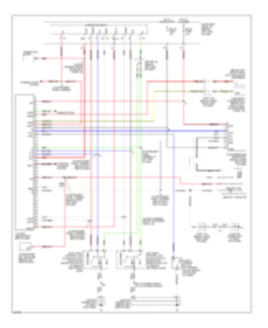
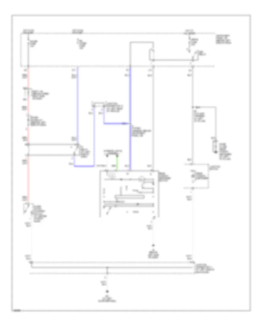
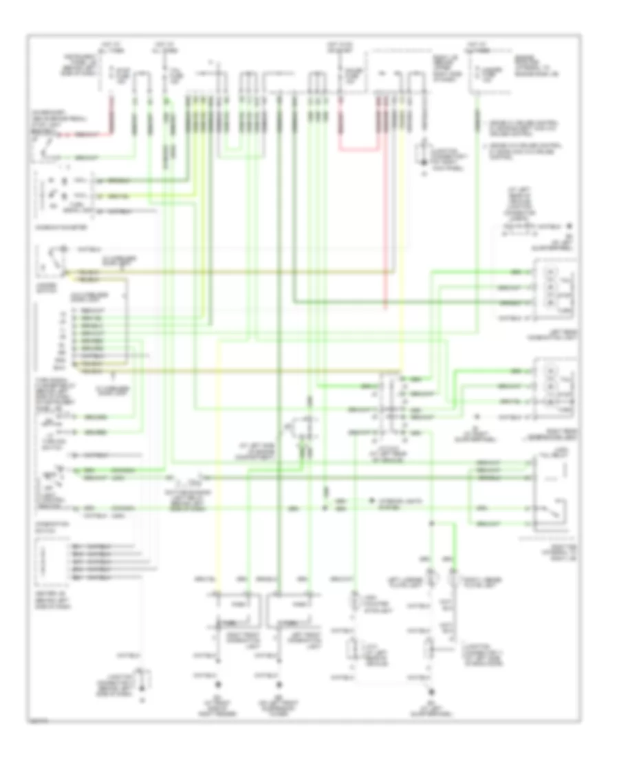
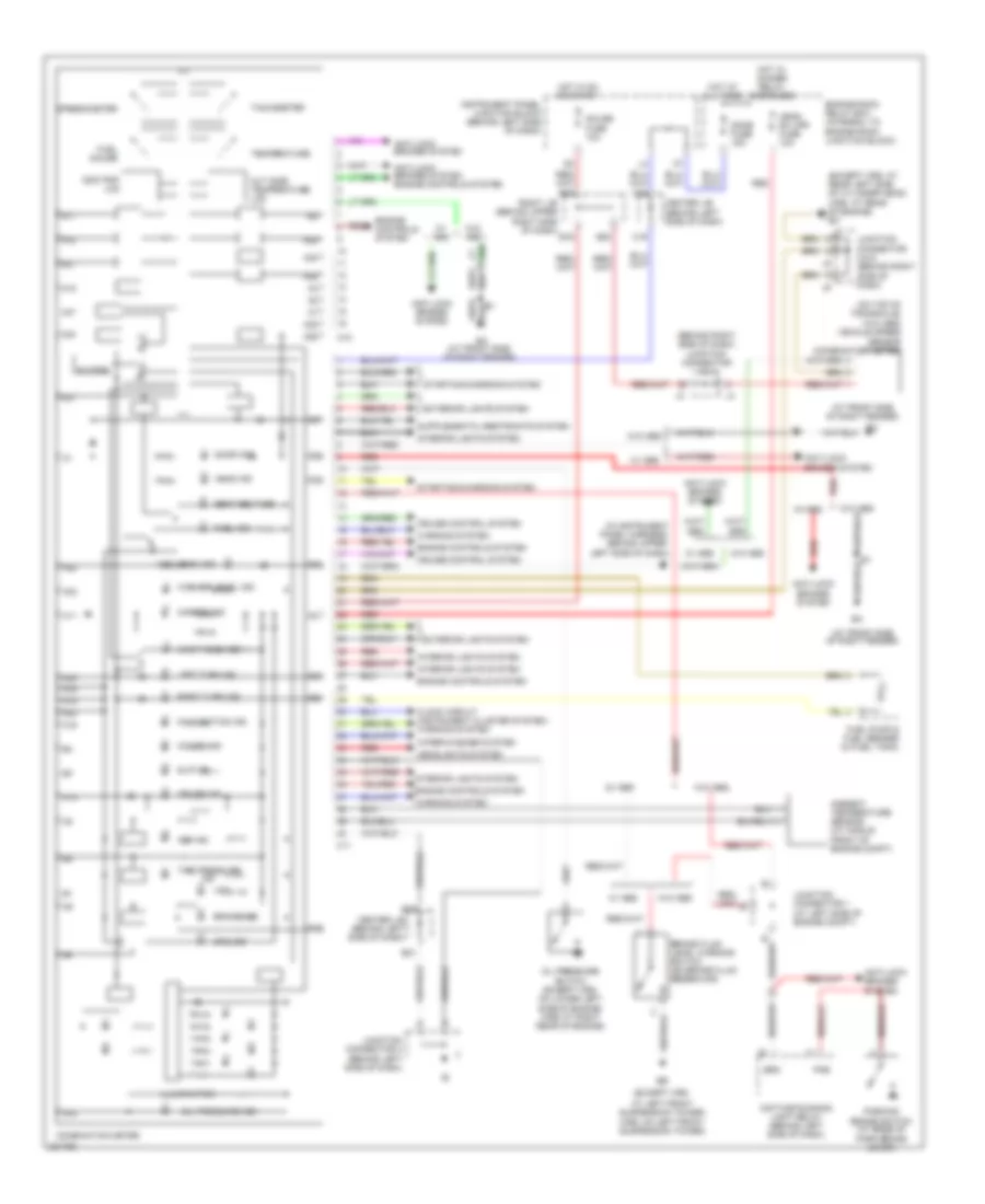
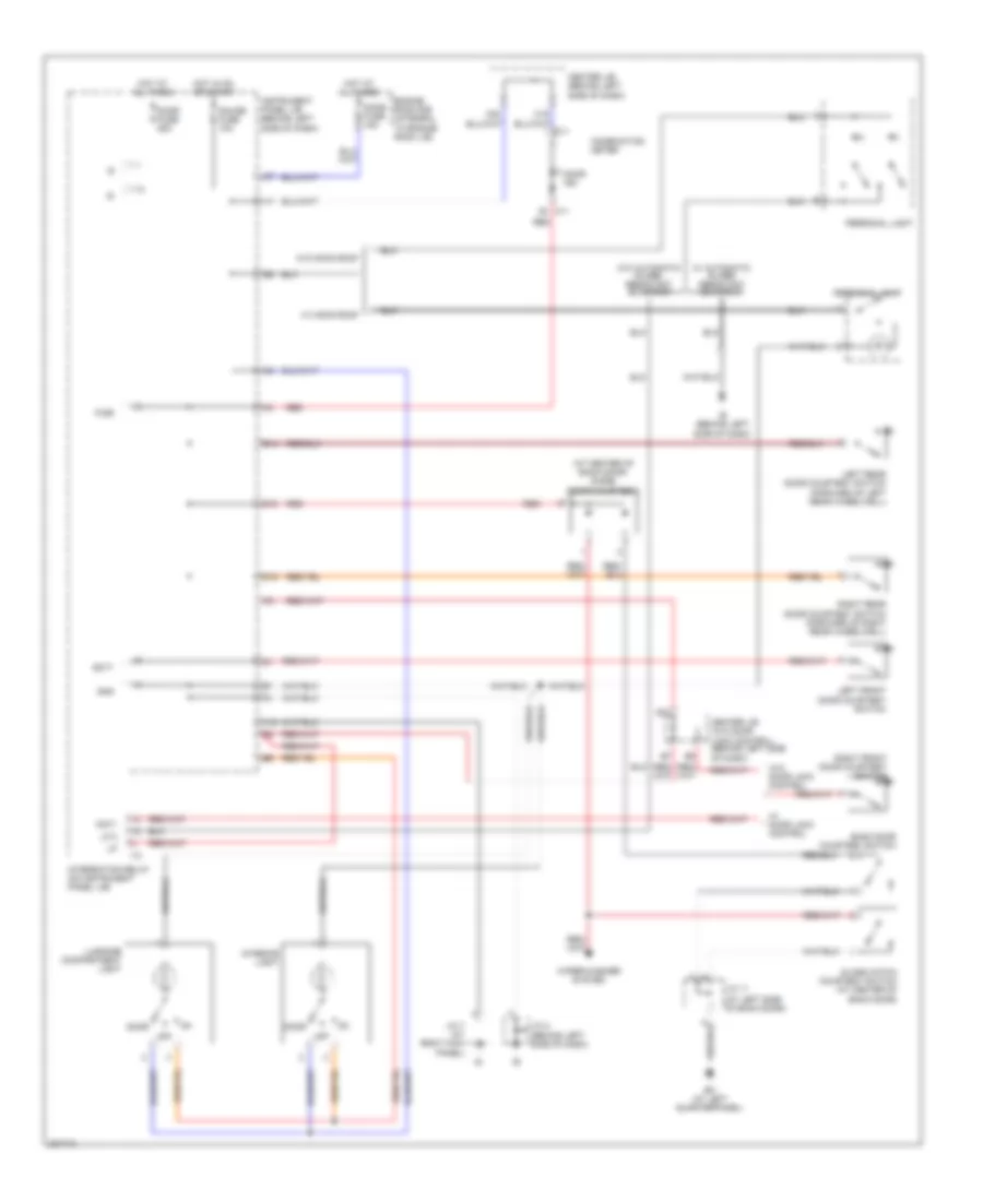
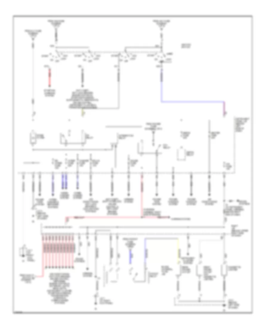
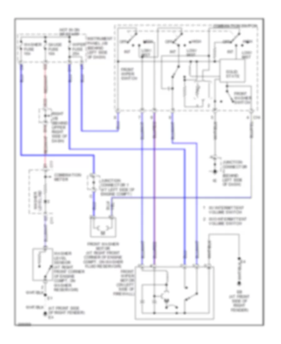
AIR CONDITIONING
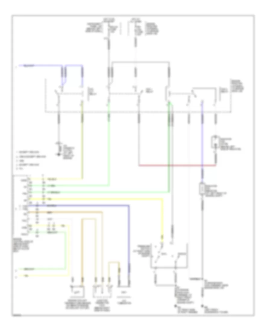
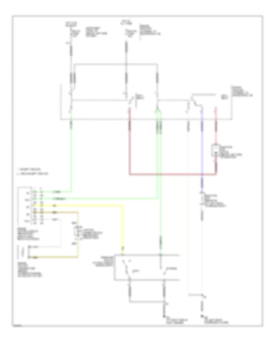
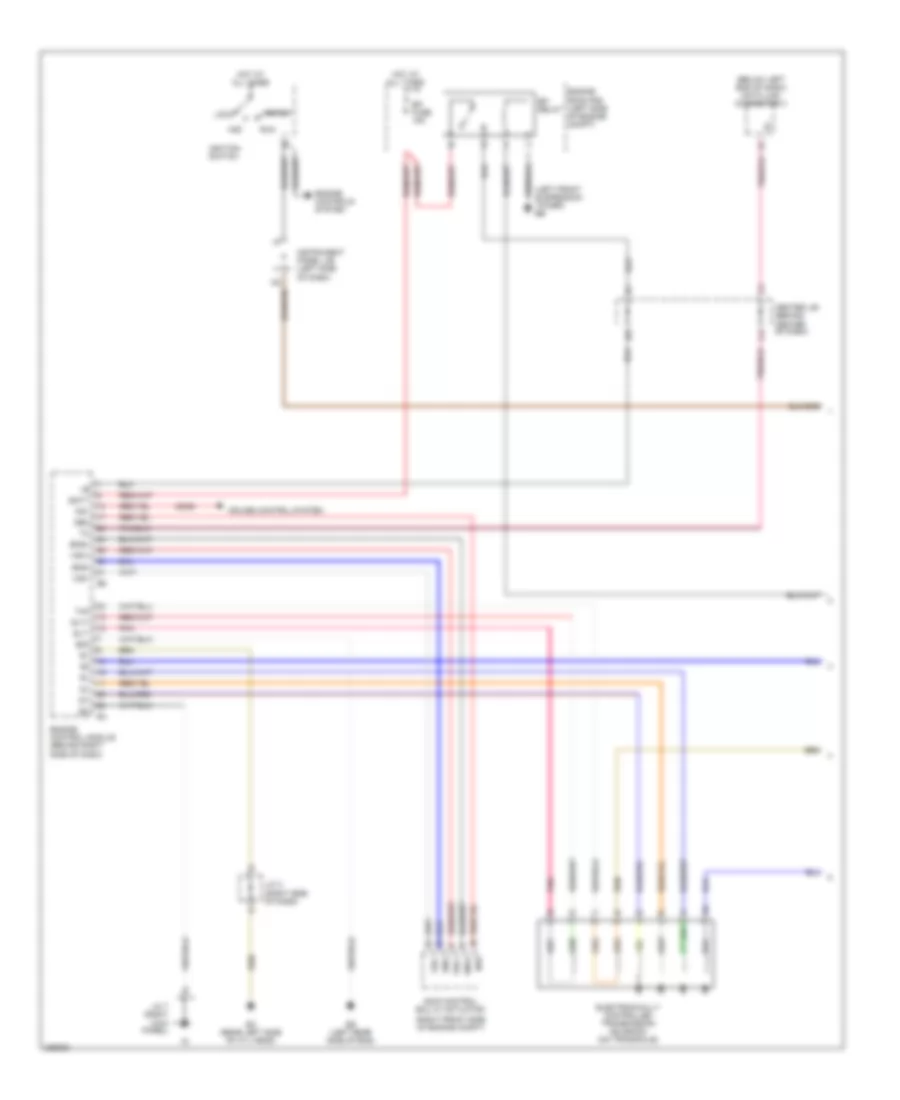
Manual A/C Wiring Diagram (1 of 2) for Toyota Matrix 2006
 https://portal-diagnostov.com/license.html
Automotive Electricians Portal FZCO
Automotive Electricians Portal FZCO
https://portal-diagnostov.com/license.html
https://portal-diagnostov.com/license.html
Automotive Electricians Portal FZCO
Automotive Electricians Portal FZCO
List of elements for Manual A/C Wiring Diagram (1 of 2) for Toyota Matrix 2006:
- (integral to right j/b) right r/b
- A/c fuse 10a
- A/c switch
- A/c switch & air inlet control switch
- A11
- A20
- Air inlet control switch
- Air inlet servo control motor (behind glove box)
- B12
- B22
- Blower motor (below right side of dash, in heater-a/c housing)
- Blower resistor (below right side of dash, in heater-a/c housing)
- Blower switch
- Defroster mode switch
- Dome fuse 15a
- Engine room r/b (integral to engine room j/b)
- Fresh
- Gauge fuse 10a
- Heater fuse 40a
- High
- Hot at all times
- Hot in on or start
- Htr relay
- I10 (in instrument panel harness, behind right end of dash)
- Illum
- Instrument panel j/b (behind left side of dash)
- Interior lights system
- Junction connector (at right kick panel)
- Junction connector 7 (at right kick panel)
- Low
- Off
- Pnk
- Recirc
- Red
- Right j/b (behind upper right side of dash)
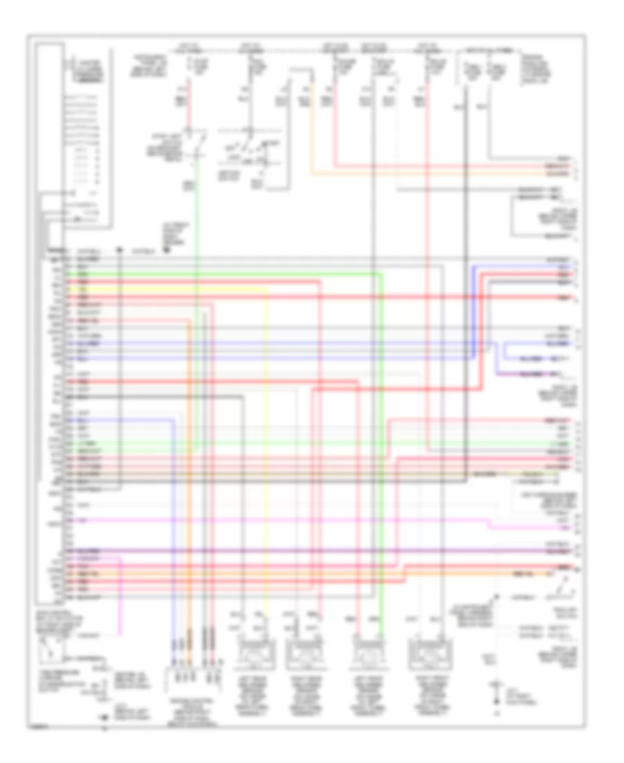
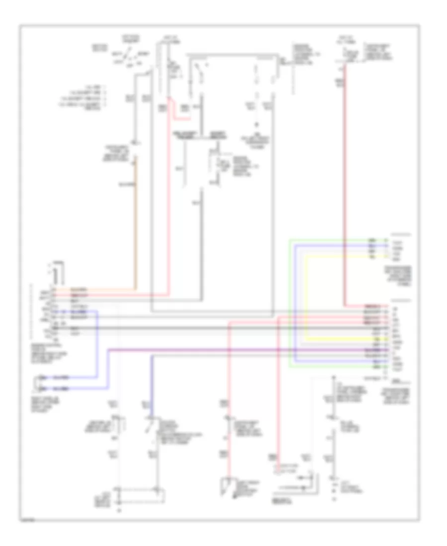
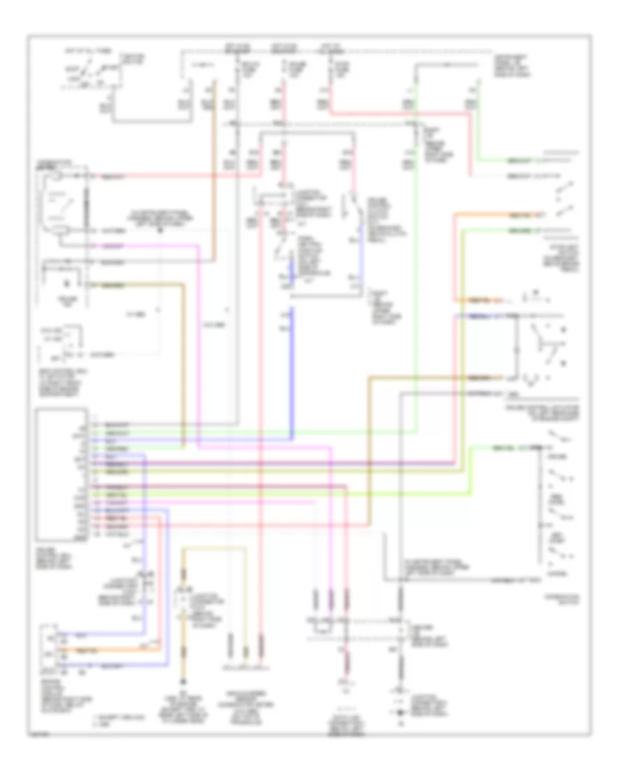
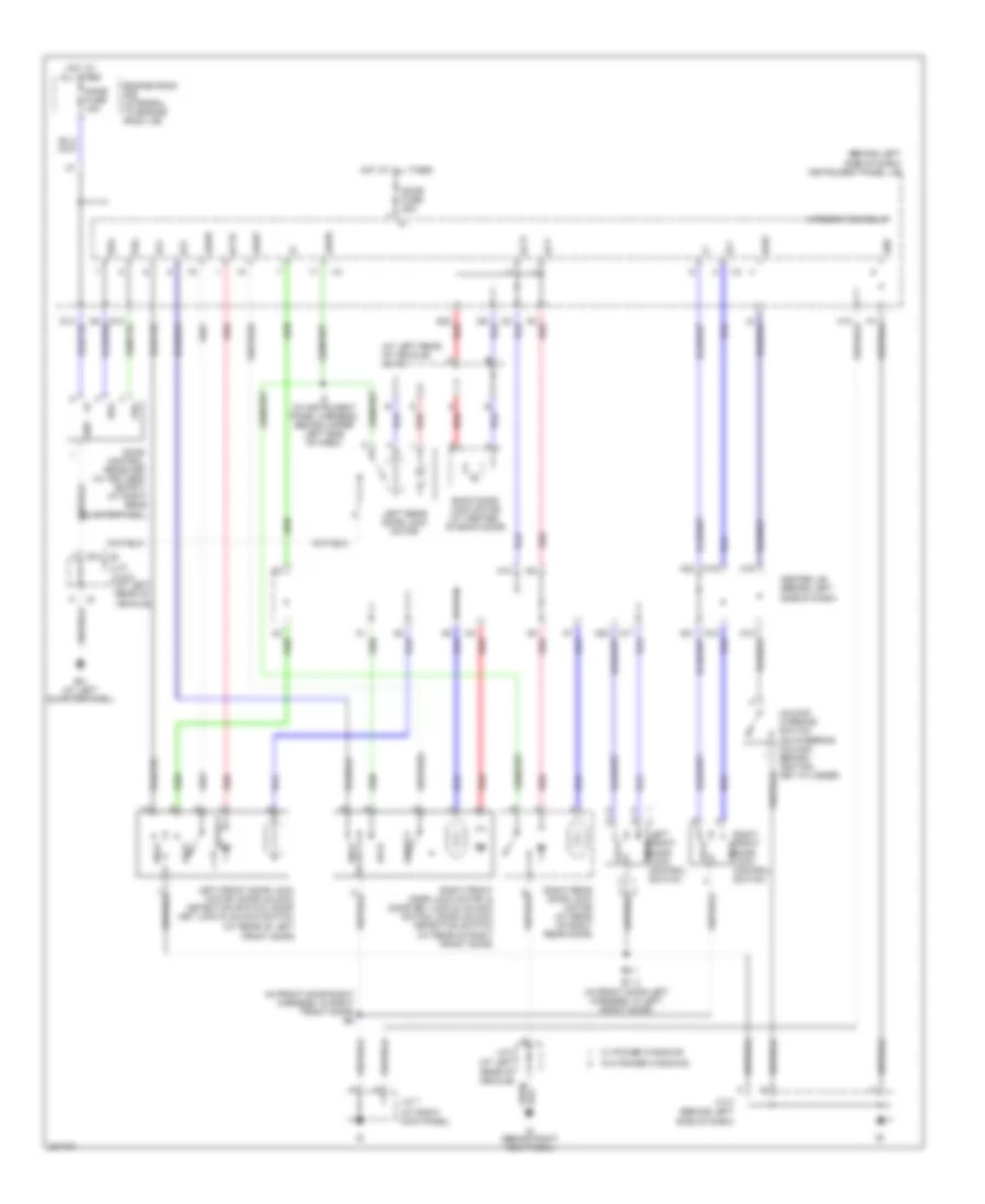
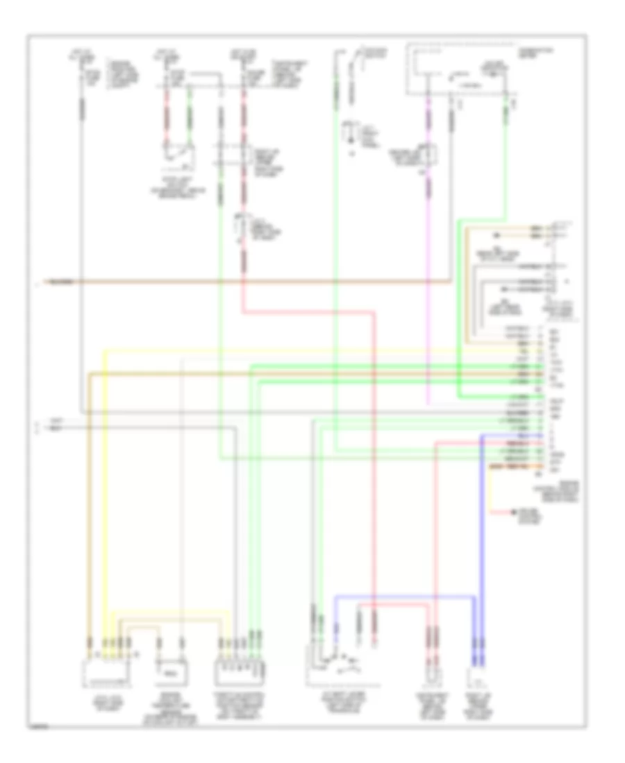
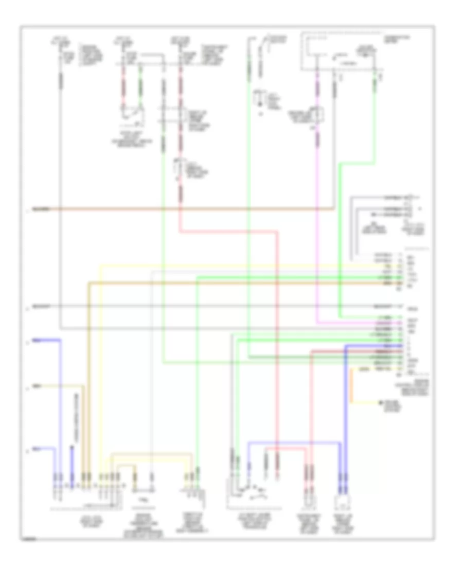
Manual A/C Wiring Diagram (2 of 2) for Toyota Matrix 2006
List of elements for Manual A/C Wiring Diagram (2 of 2) for Toyota Matrix 2006:
- (in engine room main harness, at right front corner of engine compt)
- A/c magnetic clutch (at left front of engine)
- A/c thermistor
- A/cs
- Acld
- Acmg
- All
- Dual
- E4 (in engine room main harness, near engine room j/b)
- Ea (at front side of right fender)
- Eb (left front suspension tower)
- Ecu-ig fuse 10a
- Engine control module (behind right side of dash, below glove box)
- Engine coolant temperature sensor (on rear of engine, on coolant outlet)
- Engine room r/b (integral to engine room j/b)
- Except xrs 2wd
- Except xrs 4wd
- Fan
- Fan 1 relay
- Fan 2 relay
- Hot at all times
- Hot in on or start
- Instrument panel j/b (behind left side of dash)
- J5 f
- J6 h
- Junction connector 5 & 6 (behind right side of dash)
- M/g clt relay
- Pressure switch (at right side of engine compt)
- Radiator fan motor (behind left side of radiator)
- Radiator fan resistor (at left front of engine compt)
- Rdi fan fuse 40a
- Single
- The
- Thr
- Thw
- Xrs
- Xrs & except xrs 4wd
ANTI-LOCK BRAKES
Anti-lock Brakes Wiring Diagram, with VSC (1 of 2) for Toyota Matrix 2006
List of elements for Anti-lock Brakes Wiring Diagram, with VSC (1 of 2) for Toyota Matrix 2006:
- (at front side of right fender) ea
- A11
- A22
- Abs 1 fuse 30a
- Abs 2 fuse 50a
- Acc
- Am2 fuse 15a
- B14
- B21
- Brl
- Bz +bs
- C13
- C14
- Canh
- Canl
- Center j/b (behind left side of dash)
- Csw
- D/g
- Ecu-b fuse 10a
- Ecu-ig fuse 10a
- Eng+
- Eng-
- Engine control module (behind right side of dash, below glove box)
- Engine room r/b (integral to engine room j/b)
- Fl+
- Fl-
- Fr+
- Fr-
- Gauge fuse 10a
- Gnd1
- Gnd2
- Hot at all times
- Hot in on or start
- I9 (in instrument panel harness, behind right end of dash)
- Ig1
- Ignition switch
- Ind
- Init
- Instrument panel j/b (behind left side of dash)
- J/c 2 (behind left side of dash)
- J/c 7 (at right kick panel)
- Left front abs speed sensor (on inside of left front wheel assembly)
- Left rear abs speed sensor (on inside of left rear wheel assembly)
- Lock
- Master cylinder pressure sensor
- Mrf
- Neo
- Off
- Pkb
- Pnk
- Red
- Right front abs speed sensor (on inside of right front wheel assembly)
- Right j/b (behind upper right side of dash)
- Right rear abs speed sensor (on inside of right rear wheel assembly)
- Rl+
- Rl-
- Rr+
- Rr-
- Skid control ecu w/ actuator (at right side of engine compt)
- Sp1
- Start
- Stop fuse 15a
- Stop light switch (on bracket, above brake pedal)
- Stp
- Tire pressure warning standardization switch
- Trac off switch
- Trc+
- Trc-
- Tsi
- Vsc warning buzzer (behind left side of dash)
- Vsc+
- Vsc-
- Vscw
- Wfse
- Wtir
Anti-lock Brakes Wiring Diagram, with VSC (2 of 2) for Toyota Matrix 2006
List of elements for Anti-lock Brakes Wiring Diagram, with VSC (2 of 2) for Toyota Matrix 2006:
- (at base of park brake lever) parking brake switch
- (behind left side of dash) daytime running light relay
- Abs ind
- Abs mtr cut relay
- Abs mtr relay
- Abs r/b (on left side of engine compt)
- B16
- B20
- B22
- Batt
- Brake ind
- Brk
- C11
- C18
- C19
- C20
- Canh
- Canl
- Center j/b (behind left side of dash)
- Combination meter
- Data link connector 3 (below left side of dash)
- Dome fuse 15a
- Ec (xrs: at rear of engine) (except xrs: at rear left side of cylinder head)
- Engine room r/b (integral to engine room j/b)
- Ess
- Gnd
- Harness, behind right end of dash) i9
- Hot at all times
- I9 (in instrument panel harness, behind right end of dash)
- Ig1
- Ind pressure tire
- Instrument panel j/b (behind left side of dash)
- J/c 1 (at left side of engine compt)
- J/c 13 (behind left side of dash)
- J/c 3 (behind right side of dash)
- J/c 5 (behind right side of dash)
- Park/neutral position switch (on left side of transaxle)
- Pkb
- Pnk
- Red
- Right j/b (behind upper right side of dash)
- Sil
- Slip ind
- Speedometer
- Steering wheel sensor (behind steering wheel)
- Vsc ind
- Wfse
- Yaw rate sensor (under left front seat)
Anti-lock Brakes Wiring Diagram, without VSC for Toyota Matrix 2006
List of elements for Anti-lock Brakes Wiring Diagram, without VSC for Toyota Matrix 2006:
- (at front side of right fender) ea
- (at left side of engine compartment) j/c 1
- (at right side of engine compt) skid control ecu w/ actuator
- (behind left side of dash) instrument panel j/b
- (behind upper right side of dash) right j/b
- (on bracket, above brake pedal) stop light switch
- +bm
- +bs
- Abs 1 fuse 30a
- Abs 2 fuse 40a
- Abs deceleration sensor (4wd) (under left front seat)
- Abs ind
- Acc
- Am2 fuse 15a
- B14
- B16
- B20
- B21
- B22
- Brake fluid level warning switch (on brake fluid reservoir)
- Brake ind
- Brk
- Brl
- C11
- C13
- C14
- C18
- C19
- C20
- Center j/b (behind left side of dash)
- Combination meter
- D/g
- Data link connector 3 (below left side of dash)
- Daytime running light relay (behind left side of dash)
- Dome fuse 15a
- Eb (at left front suspension tower)
- Ec (except xrs: at rear left side of cylinder head) (xrs: at rear of engine)
- Ecu-ig fuse 10a
- Engine room r/b (integral to engine room j/b)
- Fl+
- Fl-
- Fr+
- Fr-
- Gauge fuse 10a
- Ggnd
- Gl1
- Gnd1
- Gnd2
- Hot at all times
- Hot in on or start
- Ig1
- Ignition switch
- Ind tire pressure
- Init
- Instrument panel j/b (behind left side of dash)
- J/c 2 (behind left side of dash)
- J/c 3 (behind right side of dash)
- J/c 5 (behind right side of dash)
- Left front abs speed sensor (on inside of left front wheel assembly)
- Left rear abs speed sensor (on inside of left rear wheel assembly)
- Left rear abs speed sensor (on inside of right rear wheel assembly)
- Lock
- Off
- Park/neutral position switch (on left side of transaxle)
- Parking brake switch (at base of park brake lever)
- Pkb
- Red
- Right front abs speed sensor (on inside of right front wheel assembly)
- Right j/b (behind upper right side of dash)
- Rl+
- Rl-
- Rr+
- Rr-
- Sil
- Sp1
- Speedometer
- Start
- Stop fuse 15a
- Stp
- Tire pressure warning standardization switch
- Tsi
- Vgs
- Wtir
ANTI-THEFT
Forced Entry Wiring Diagram for Toyota Matrix 2006
List of elements for Forced Entry Wiring Diagram for Toyota Matrix 2006:
- (behind left side of dash) daytime running light relay
- (in dash harness, behind instrument panel j/b)
- (in instrument panel harness, behind right end of dash)
- (in instrument panel harness, behind upper left side of dash)
- (w/ power window) (w/o power window)
- +b1
- A11
- A19
- B2 b1
- Center j/b (behind left side of dash)
- Combination meter
- Cty
- Dcty
- Detection
- Dmlp
- Dswd
- Ecu-b fuse 10a
- Ecu-ig fuse 10a
- Ehw
- Glass breakage sensor ecu (behind upper right end of dash)
- Gnd
- Head
- Horn
- Horns system
- Hot at all times
- Hot in on or start
- Hzad
- I1 (in instrument panel harness, at left side of dash)
- I10
- I10 (in instrument panel harness, behind right end of dash)
- I12
- I2 (in dash harness, behind instrument panel j/b)
- I9 (in instrument panel harness)
- Ind
- Instrument panel j/b (behind left side of dash)
- Integration relay
- Interior lights system
- Iout
- Irsg
- Junction connector 2 (behind left side of dash)
- Junction connector 7 (at right kick panel)
- Junction connector 7 (at right kick panel)
- Ksw
- Left front door key lock & unlock switch, door unlock detection switch (at rear of left front door)
- Lock
- Lswd
- Lswp
- Mic
- Mic-
- Micro- phone
- Nca
- P-dr
- Red
- Right front door key lock & unlock switch, door unlock detection switch (at rear of right front door)
- Right j/b (behind upper right side of dash)
- S+b
- Security ind
- Security indicator
- Srly
- Starting/ charging system
- Transponder key computer (behind left side of dash)
- Trig
- Turn signal flasher relay (behind left side of dash, on instrument panel j/b)
- Tvip ecu (behind right end of dash)
- Ul2
- Ul3
- Unlk
- Unlock warning switch (on steering column, behind ignition key cylinder)
Immobilizer Wiring Diagram for Toyota Matrix 2006
List of elements for Immobilizer Wiring Diagram for Toyota Matrix 2006:
- (at right kick panel)
- (on left front
- (w/ tvip)
- (w/0 tvip)
- 1.8l except xrs
- 1.8l except xrs 2wd
- 1.8l xrs
- 1.8l xrs & 1.8l except xrs 4wd
- 20a
- A11
- A19
- Acc
- Agnd
- B13
- B21
- Batt
- Center j/b (behind left side of dash)
- Code
- Cty
- Ecu-b fuse 10a
- Efi 2 fuse 15a
- Efi fuse 15a
- Efi relay
- Efii
- Efio
- End of dash)
- Engine control module (behind right side of dash, below glove box)
- Engine room r/b (integral to engine
- Engine room r/b (integral to engine room j/b)
- Eom
- Except except xrs 2wd xrs 2wd
- Gnd
- Hot at all times
- Hot in on or start
- Ignition switch
- Igsw
- Imi
- Imo
- Ind
- Instrument panel j/b (behind left side of dash)
- J/c 2 (at left rear of vehicle)
- J/c 7
- Ksw
- Left front door courtesy switch
- Lock
- Mrel
- Off
- Rh j/b (integral to rh j/b)
- Right side j/b (behind upper right side of dash)
- Room j/b)
- Security indicator
- Sil
- Start
- Suspension
- Tower)
- Transponder key amplifier (right side of steering wheel)
- Transponder key computer (behind left side of dash)
- Txct
- Unlock warning switch (on steering column, behind ignition key cylinder)
- Vcs
- Xrs, except xrs, except xrs 4wd xrs 4wd
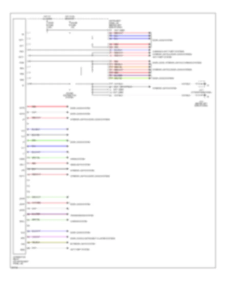
BODY CONTROL MODULES
Body Control Modules Wiring Diagram for Toyota Matrix 2006
List of elements for Body Control Modules Wiring Diagram for Toyota Matrix 2006:
- (not used)
- Act+
- Act-
- Actd
- Actg
- Anti-theft system
- Bckl
- D10
- D14
- D15
- D16
- D20
- Dcty
- Door fuse 25a
- Door locks & instrument cluster systems
- Door locks system
- Door locks systems
- Door locks, interior lights & warning systems
- Exterior lights system
- Gauge fuse 10a
- Gls
- Gnd
- H10
- Haz
- Headlights system
- Horn
- Horns system
- Hot at all times
- Hot in on or start
- Hrly
- I10
- Instrument panel j/b (behind left side of dash)
- Integration relay (on instrument panel j/b)
- Interior lights & door locks systems
- Interior lights system
- Irsg
- J/c 2 (behind left side of dash)
- J/c 7 (at right kick panel)
- Ksw
- Lp2
- Lswd
- Lswp
- Lswr
- P-dr
- Pcty
- Power distribution system
- Prg
- Rda
- Red
- Spd
- Transmissions system
- Ul1
- Ul2
- Ul3
- Warning & anti-theft systems
- Warning system
COMPUTER DATA LINES
Computer Data Lines Wiring Diagram for Toyota Matrix 2006
List of elements for Computer Data Lines Wiring Diagram for Toyota Matrix 2006:
- (in dash harness, behind instrument panel j/b) i2
- A j3
- A j4
- A13
- Air bag sensor assembly (below center of dash)
- B16
- B21
- Bat
- C11
- Canh
- Canl
- Canl
- Center j/b (behind left side of dash)
- Combination meter
- Cruise control ecu (behind left side of dash)
- D/g
- Data link connector 3 (below left side of dash)
- Dia
- Ec (except xrs: at rear left side
- Engine control module (behind right side of dash, below glove box)
- Except xrs
- Hot at all times
- Instrument panel j/b (behind left side of dash)
- J/c 13 (behind left side of dash)
- J/c 2 (behind left side of dash)
- J/c 3 & 4 (behind right side of dash)
- Obd fuse 7.5a
- Occupant classification ecu (under front passenger seat)
- Of cylinder head) (xrs: at rear
- Of engine)
- Pnk
- Right j/b (behind upper right side of dash)
- Sil
- Skid control ecu with actuator (at right front side of engine compartment)
- Steering sensor
- Wfse
- Xrs
- Yaw rate sensor (under left front seat)
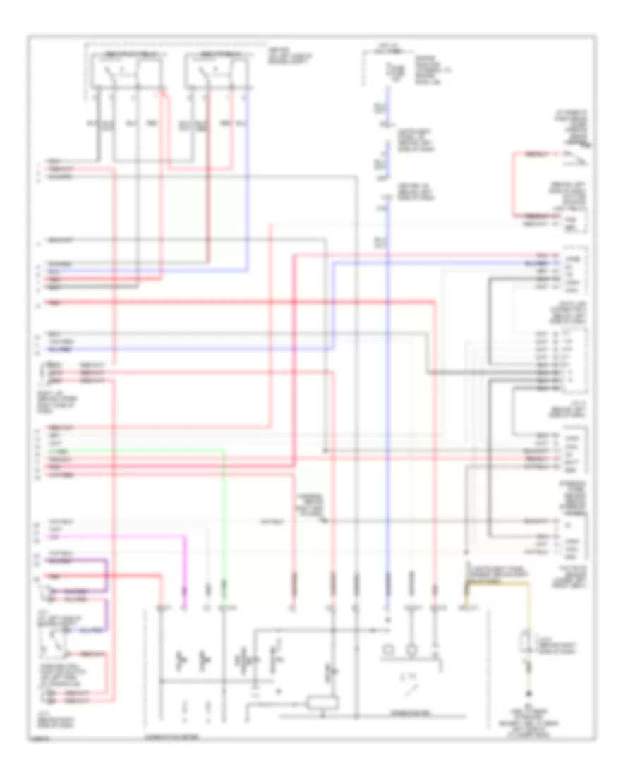
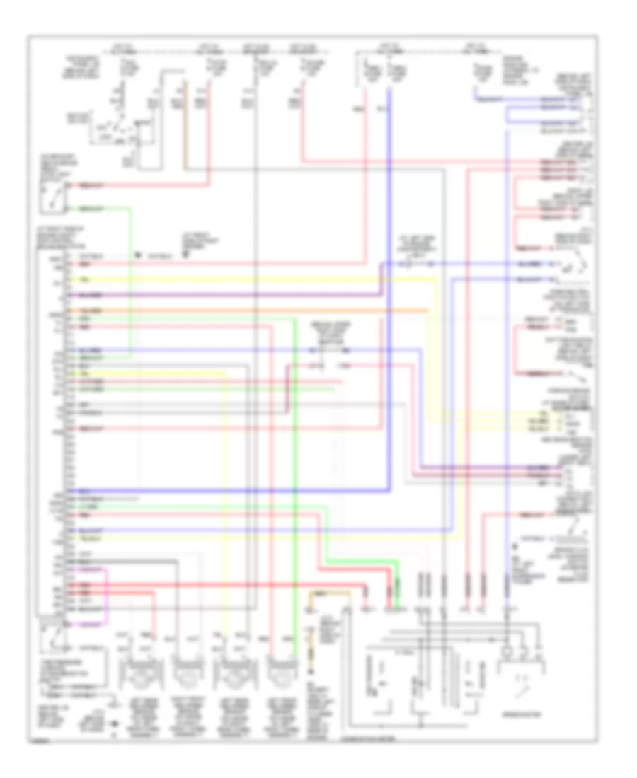
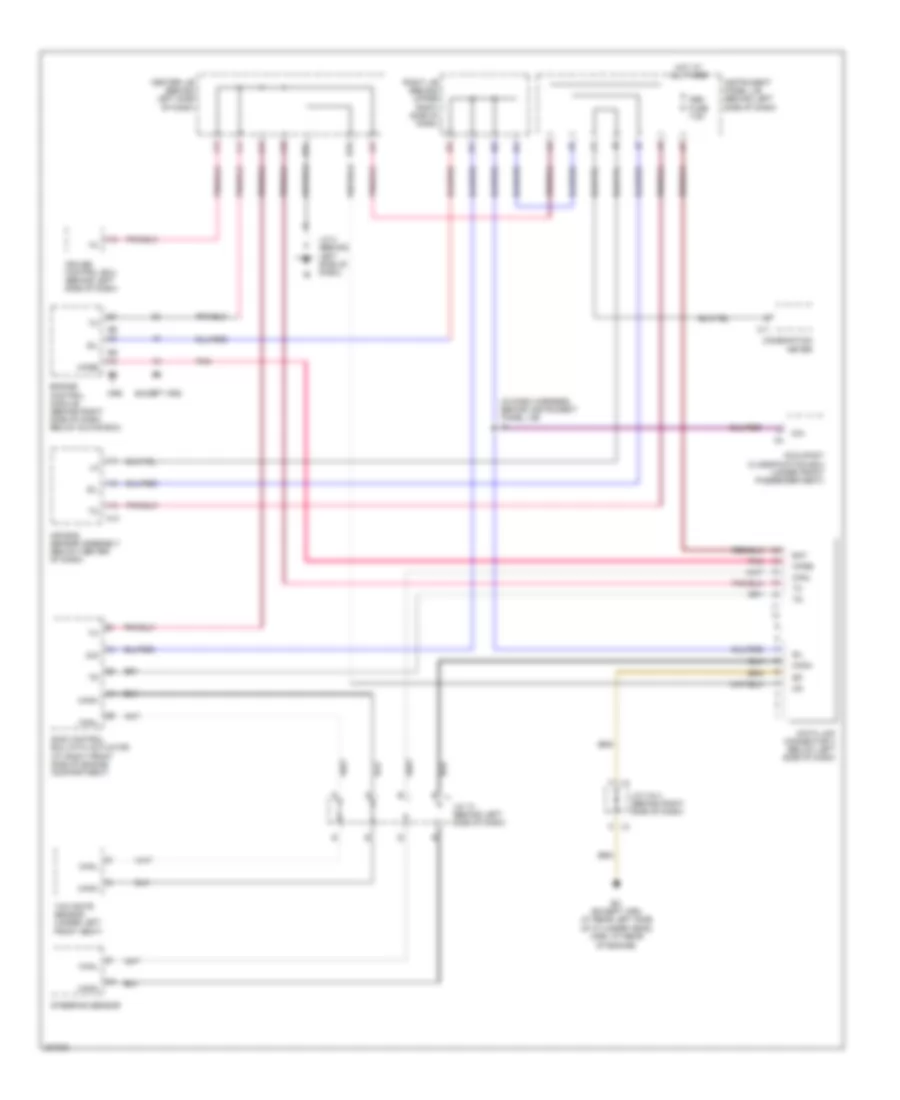
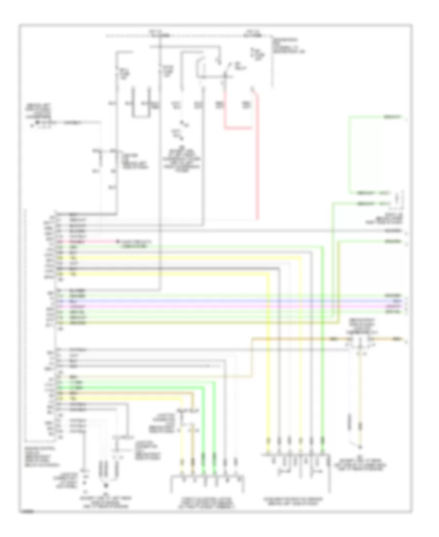
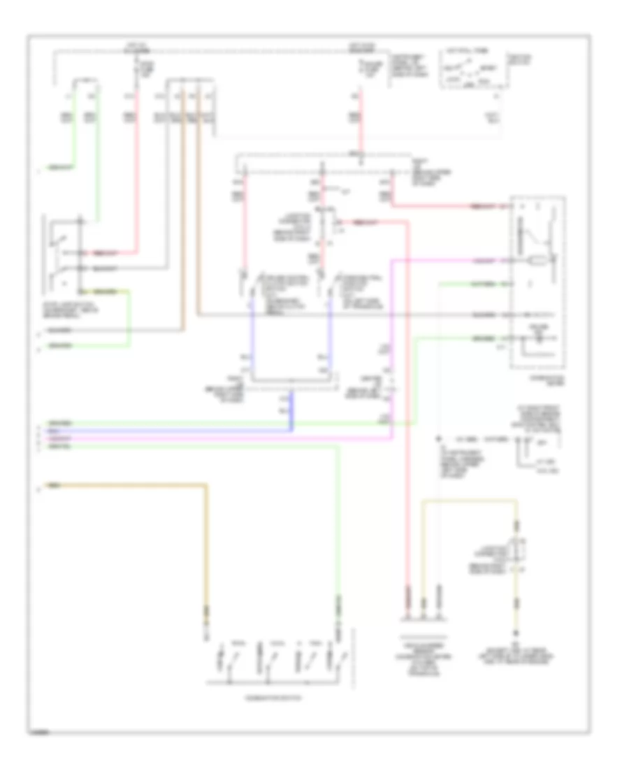
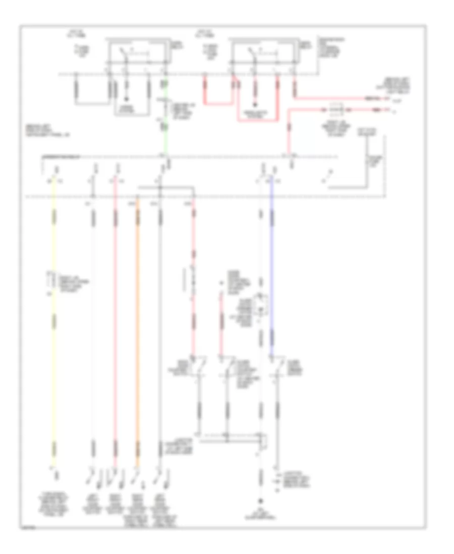
COOLING FAN
Cooling Fan Wiring Diagram for Toyota Matrix 2006
List of elements for Cooling Fan Wiring Diagram for Toyota Matrix 2006:
- C13
- Dual
- Ea (at front side of right fender)
- Eb (on left front suspension tower)
- Ecu-ig fuse 10a
- Engine control module (behind right side of dash, below glove box)
- Engine coolant temperature sensor (on rear of engine, on coolant outlet)
- Engine room r/b (integral to engine room j/b)
- Except xrs 2wd
- Fan
- Fan 1 relay
- Fan 2 relay
- Hot at all times
- Hot in on or start
- Instrument panel j/b (behind left side of dash)
- J5 f
- Junction connector 5 & 6 (behind right side of dash)
- Pressure switch (at right side of engine compt)
- Radiator fan motor (behind left side of radiator)
- Radiator fan resistor (at left front of engine compt)
- Rdi fan fuse 40a
- Single
- Thw
- Xrs & except xrs 4wd
CRUISE CONTROL
Cruise Control Wiring Diagram, Except XRS for Toyota Matrix 2006
List of elements for Cruise Control Wiring Diagram, Except XRS for Toyota Matrix 2006:
- (behind j5 right side of dash)
- (behind upper right side of dash)
- (in instrument panel harness, behind upper left side of dash) i5
- A/t
- Acc
- B j3
- B12
- B16
- B19
- B20
- B21
- B22
- C j4
- C12
- C13
- C14
- C17
- C19
- C20
- Cancel
- Ccs
- Center j/b (behind left side of dash)
- Combination meter
- Combination switch
- Cruise
- Cruise control actuator (on left rear side of engine compt)
- Cruise control clutch switch (m/t) (on bracket, above clutch pedal)
- Cruise control ecu (behind left side of dash)
- Cruise ind
- Data link connector 3 (below left side of dash)
- Ec (xrs: at rear of engine) (except xrs: at rear left side of cylinder head)
- Ecc
- Ect
- Ecu-ig fuse 10a
- Engine control module (behind right side of dash, below glove box)
- Except xrs 4wd
- Gauge fuse 10a
- Gnd
- Hot at all times
- Hot in on or start
- Idl
- Idlo
- Ignition switch
- Instrument panel j/b (behind left side of dash)
- Junction connector 2 (behind left side of dash)
- Junction connector 3 & 4 (behind right side of dash)
- Junction connector 5 & 6
- Junction connector 5 & 6 (behind right side of dash)
- Lock
- Od1
- Off
- Park/ neutral position switch (on left side of transaxle)
- Res/ accel
- Right j/b
- Right j/b (behind upper right side of dash)
- Set/ coast
- Skid control ecu w/ actuator (at right front side of engine compartment)
- Sp1
- Spd
- Speedometer
- Start
- Stop fuse 15a
- Stoplight switch (on bracket, above brake pedal)
- Stp-
- Vehicle speed sensor (combination meter) (w/o abs) (on top of transaxle)
- W/ abs
- W/ vsc
- W/o abs
- W/o vsc
- Xrs
Cruise Control Wiring Diagram, XRS (1 of 2) for Toyota Matrix 2006
List of elements for Cruise Control Wiring Diagram, XRS (1 of 2) for Toyota Matrix 2006:
- (behind left side of dash) junction connector 2
- (behind right side of dash) junction connector 3 & 4
- +bm
- Accelerator position sensor (behind left side of dash)
- All times
- B j4
- B j6
- B13
- B21
- Batt
- C j3
- C11
- C13
- Ccs
- Center j/b (behind left side of dash)
- Computer data lines system
- E01
- E02
- E03
- E04
- Eb (except xrs: at left front suspension tower, xrs: on left front suspension tower)
- Ec (except xrs: at rear left side of cylinder head, xrs: at rear of engine)
- Ed (except xrs: at left rear side of engine, xrs: at rear of engine)
- Efi 2 fuse 15a
- Efi fuse 20a
- Efi relay
- Engine control module (behind right side of dash, below glove box)
- Engine room r/b (integral to engine room j/b)
- Eom
- Ep1
- Ep2
- Epa
- Epa2
- Etcs fuse 10a
- Geo1
- H j6
- Hot at
- Hot at all times
- Igsw
- J5 f
- Junction connector 3 & 4 (behind right side of dash)
- Junction connector 5 & 6 (behind right side of dash)
- Junction connector 7 (at right kick panel)
- Me01
- Mrel
- Nca
- Right j/b (behind upper right side of dash)
- Spd
- St1-
- Stp
- Throttle control motor throttle position sensor (on throttle body assembly)
- Vcp1
- Vcp2
- Vcpa
- Vpa
- Vpa2
- Vta1
- Vta2
Cruise Control Wiring Diagram, XRS (2 of 2) for Toyota Matrix 2006
List of elements for Cruise Control Wiring Diagram, XRS (2 of 2) for Toyota Matrix 2006:
- (at right front side of engine compartment) skid control ecu w/ actuator
- (behind right side of dash)
- (w/ abs)
- A/t
- Acc
- B16
- B19
- B20
- B22
- C11
- C12
- C14
- C17
- C18
- C20
- Cancel
- Ccs
- Center j/b (behind left side of dash)
- Combination meter
- Combination switch
- Cruise
- Cruise control clutch switch switch (m/t) (on bracket, above clutch pedal)
- Cruise ind
- Ec (except xrs: at rear left side of cylinder head, xrs: at rear of engine)
- Ecc
- Gauge fuse 10a
- Hot at all times
- Hot in on or start
- I5 (in instrument panel harness, behind upper left side of dash)
- Ignition switch
- Instrument panel j/b (behind left side of dash)
- Junction connector 5 & 6
- Junction connector j3 & j4 (behind right side of dash)
- Lock
- Off
- Park/neutral position switch (a/t) (on left side of transaxle)
- Res/acc
- Right j/b (behind upper right side of dash)
- Run
- Set/coast
- Sp1
- Speedometer
- Start
- Stop fuse 15a
- Stop lamp switch (on bracket, above brake pedal)
- Vehicle speed sensor (combination meter) (w/o abs) (on top of transaxle)
- W/ vsc
- W/o vsc
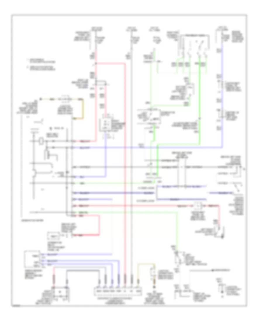
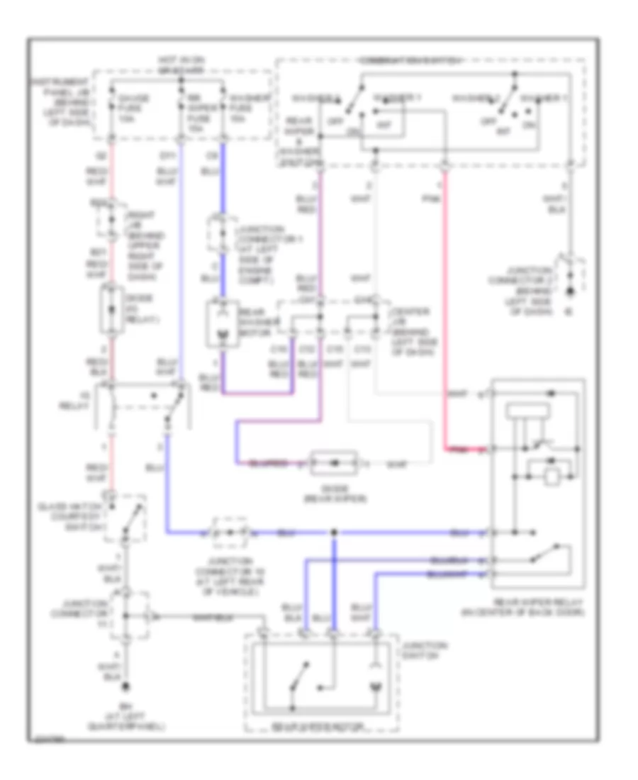
DEFOGGERS
Defoggers Wiring Diagram for Toyota Matrix 2006
List of elements for Defoggers Wiring Diagram for Toyota Matrix 2006:
- B21
- B22
- B7 (in floor harness, at left "d" pillar)
- Bh (at left quarterpanel)
- D11
- Def relay
- Defog fuse 30a
- Diode (ig relay) (behind left end of dash)
- Gauge fuse 10a
- Glass hatch courtesy switch (at center of back door)
- Hot at all times
- Hot in on or start
- I2 (in dash harness, behind instrument panel j/b)
- Ie (behind left side of dash)
- Ig relay (at left side of dash)
- Instrument panel j/b (behind left side of dash)
- Interior lights system
- Junction connector 10 (at left rear of vehicle)
- Junction connector 11 (at left side of back door)
- Junction switch
- L10
- Noise filter (rear window defogger) (at left "d" pillar)
- Rear window defogger
- Rear window defogger switch
- Right j/b (behind upper right side of dash)
- Rr wiper fuse 15a
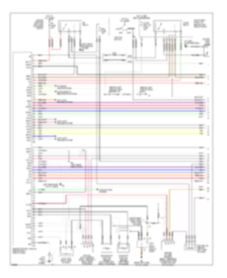
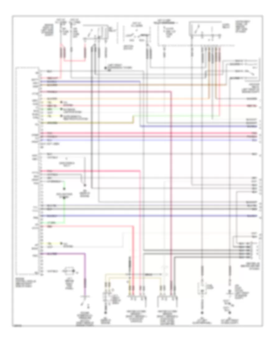
ENGINE PERFORMANCE
1.8L
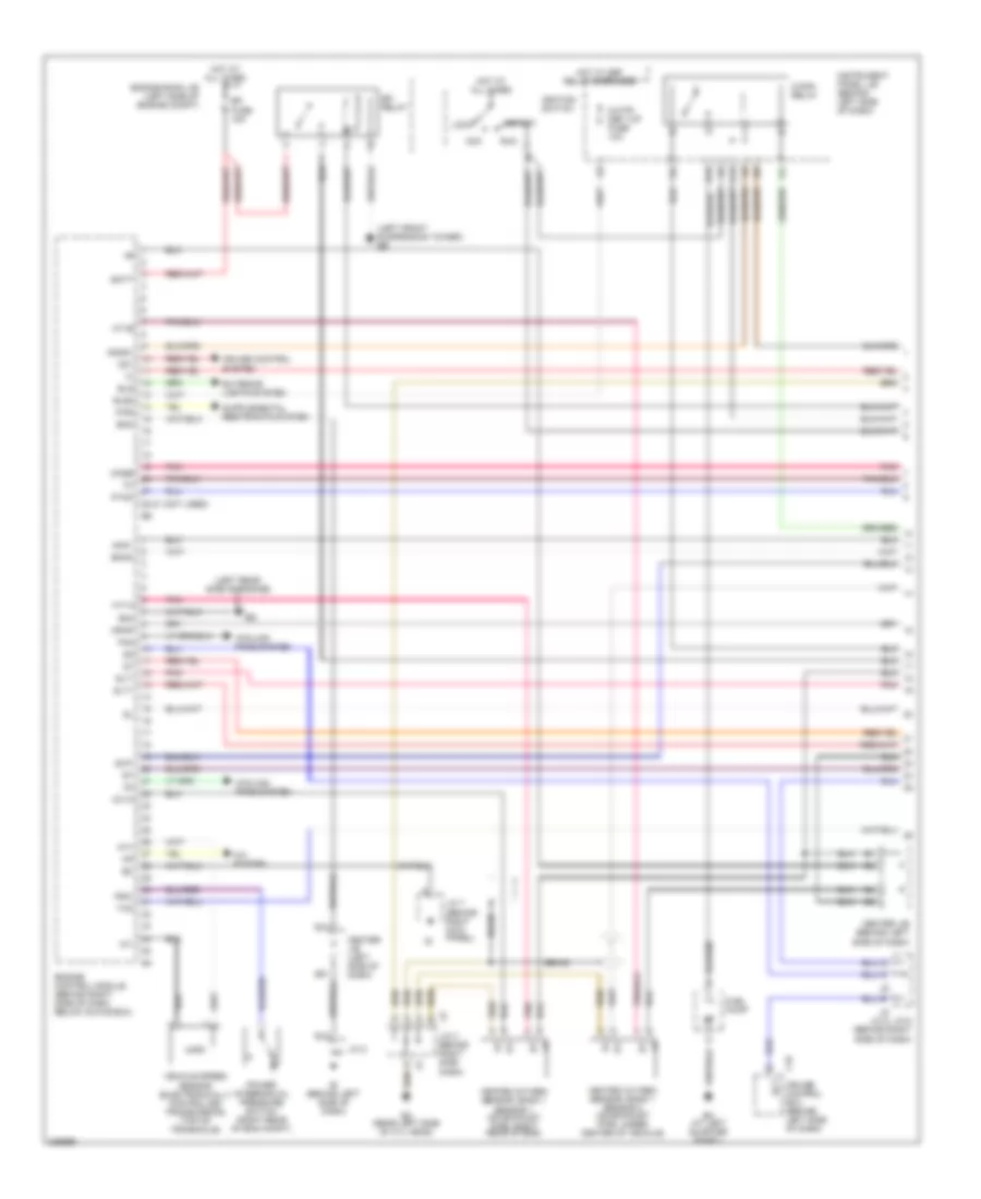
1.8L, Engine Performance Wiring Diagram, 2WD Except XRS (1 of 4) for Toyota Matrix 2006
List of elements for 1.8L, Engine Performance Wiring Diagram, 2WD Except XRS (1 of 4) for Toyota Matrix 2006:
- (at left quarterpanel) bh
- (behind left side of dash) center j/b
- (behind left side of dash) j/c 2
- (in fuel tank) fuel pump
- (instrument panel harn, right side of dash)
- (left front suspension tower) eb
- (left rear side of cyl head)
- A1a+
- A1a-
- Acc
- Af+
- Af-
- Air fuel ratio sensor (bank 1 sensor 1) (right rear of engine)
- Anti-lock brakes system
- B13
- B21
- Batt
- C/opn relay
- C12
- Camshaft position sensor (left rear of engine)
- Center j/b (behind left side of dash)
- Cooling fans system
- Crankshaft position sensor (on lower left front of engine)
- D19
- E03
- E04
- Ec (rear left side of cyl head)
- Ed (left rear side of eng)
- Efi fuse 20a
- Efi relay
- Efi2 fuse 15a
- Eknk
- Els
- Els2
- Eng+
- Eng-
- Engine control module (behind right side of dash)
- Engine room r/b (left side of engine compt)
- Eom
- Epa
- Epa2
- Exterior lights system
- F/ps
- G2+
- Ge01
- Ha1a
- Heated oxygen sensor (bank 1 sensor 2) (on exhaust pipe, under center of vehicle)
- Hot at all times
- Hot w/ def relay energized
- Ht1b
- I13
- Ignition switch
- Igsw
- Instrument panel j/b (behind left side of dash)
- J/c 3, j/c 4 (right side of dash)
- J/c 5, j/c 6 (right side of dash)
- J/c 7 (right kick panel)
- Knk1
- Lock
- M-htr/ def i-up fuse 10a
- Me01
- Mpmp
- Mrel
- Nca
- Ne+
- Ne-
- Neo
- Ox1b
- Pnk
- Ppmp
- Psw
- Run
- Sil
- Slt+
- Slt-
- Start
- Tach
- Vcp2
- Vcpa
- Vpa
- Vpa2
- Vsc+
- Vsc-
- Wfse
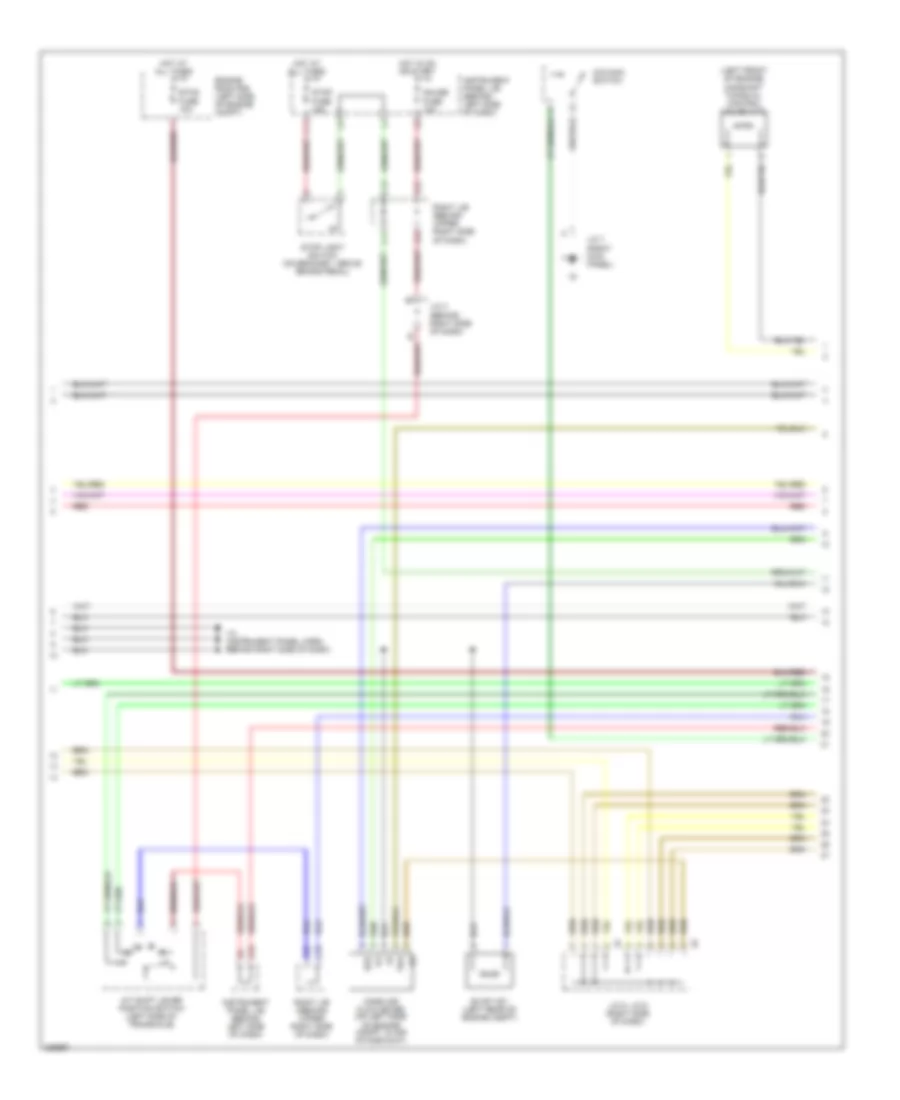
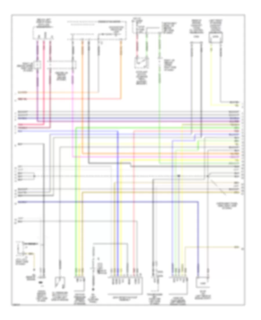
1.8L, Engine Performance Wiring Diagram, 2WD Except XRS (2 of 4) for Toyota Matrix 2006
List of elements for 1.8L, Engine Performance Wiring Diagram, 2WD Except XRS (2 of 4) for Toyota Matrix 2006:
- (left front of engine) camshaft timing oil control valve (vvt)
- A/t shift lever position switch (left side of transaxle)
- B20
- B22
- C11
- C13
- C14
- C18
- C20
- E2g
- Engine room r/b (left side of engine compt)
- Etcs fuse 10a
- Evap vsv (left rear of engine compt)
- Gauge fuse 10a
- Hot at all times
- Hot in on or start
- I12 (instrument panel harn, behind right side of dash)
- Instrument panel j/b (behind left side of dash)
- J/c 3 (behind right side of dash)
- J/c 5, j/c 6 (right side of dash)
- J/c 7 (right kick panel)
- K10
- Mass air flow meter (on left side of engine compt, in air intake duct)
- O/d main switch
- Red
- Right j/b ((behind upper right side of dash)
- Right j/b (behind upper right side of dash)
- Stop fuse 15a
- Stop light switch (on bracket, above brake pedal)
- Tha
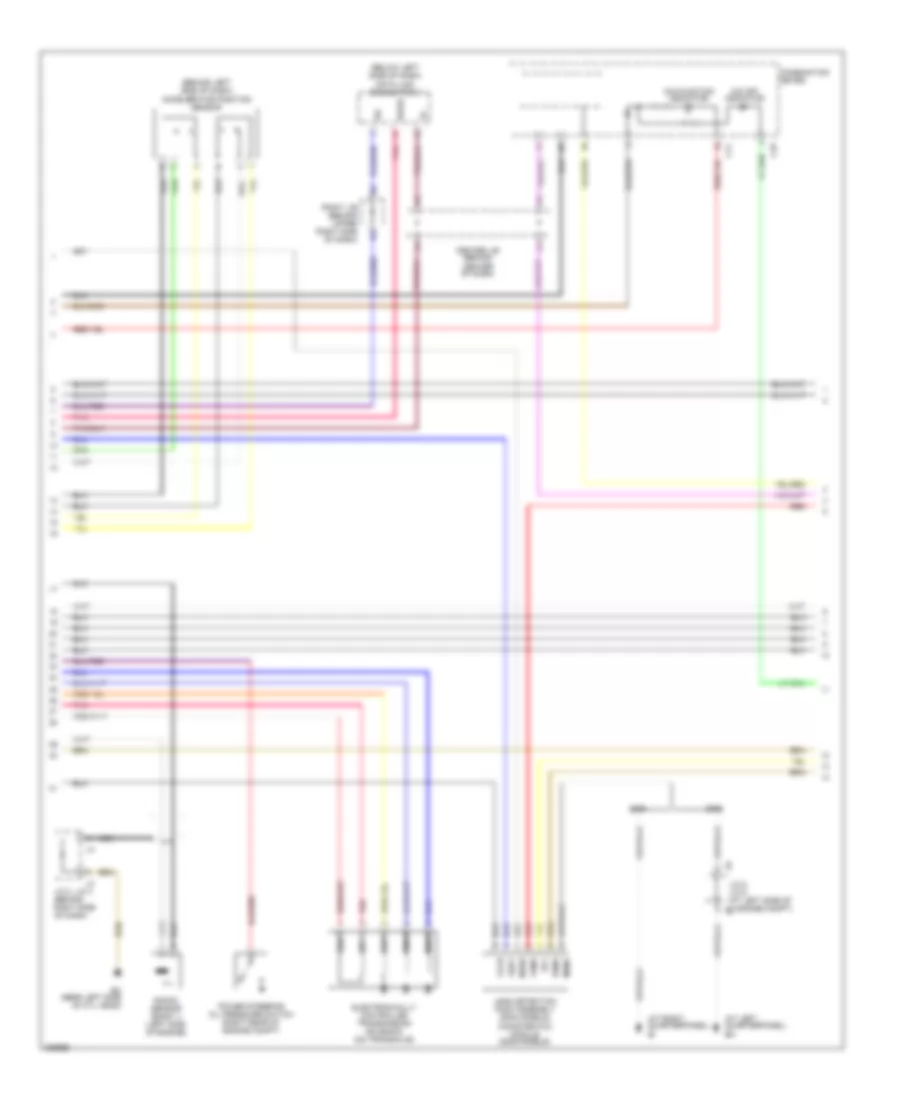
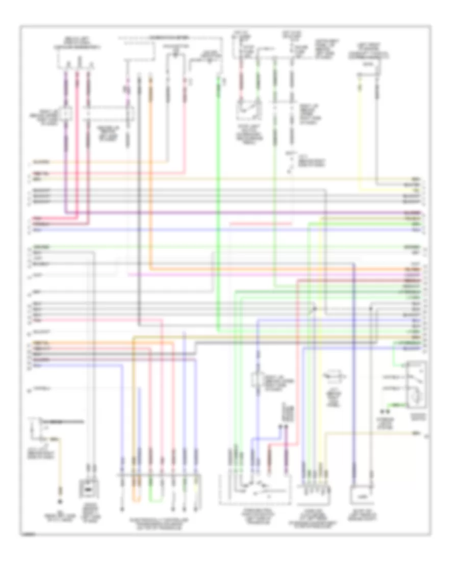
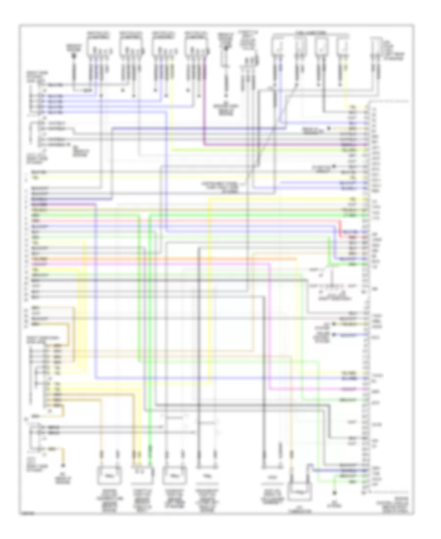
1.8L, Engine Performance Wiring Diagram, 2WD Except XRS (3 of 4) for Toyota Matrix 2006
List of elements for 1.8L, Engine Performance Wiring Diagram, 2WD Except XRS (3 of 4) for Toyota Matrix 2006:
- (at left quarterpanel) bh
- (at right quarterpanel) bi
- (behind left side of dash) accelerator position sensor
- (below left side of dash) data link connector 3
- C11
- Center j/b (behind center of dash)
- Combination meter
- Ec (rear left side of cyl head)
- Electronically controlled transmission solenoid (on transaxle)
- J/c 3, j/c 4 (behind right side of dash)
- J/c 8, j/c 9 (at left side of luggage compt) j8
- Knock sensor (bank 1) (left side of engine)
- Leak detection pump assembly (2005 models) canister pum module (2006 models)
- Malfunction indicator
- Mgnd
- Mtrb
- Nca
- O/d off indicator
- Pnk
- Power steering oil pressure switch (right rear of engine compt)
- Red
- Right j/b (behind upper right side of dash)
- Sgnd
- Sil
- Vcc
- Vgnd
- Vlvb
- Vout
- Wfse
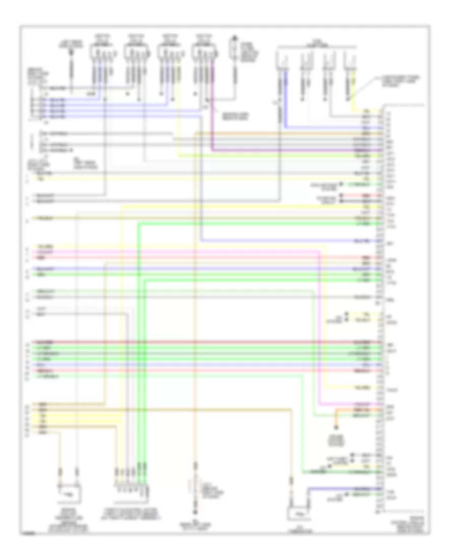
1.8L, Engine Performance Wiring Diagram, 2WD Except XRS (4 of 4) for Toyota Matrix 2006
List of elements for 1.8L, Engine Performance Wiring Diagram, 2WD Except XRS (4 of 4) for Toyota Matrix 2006:
- (behind right side of dash) j/c 5, j/c 6
- (engine harn, rear of eng)
- (instrument panel harn, right side of dash)
- (left rear side of eng) ed
- +bm
- A/c system
- A/c thermistor
- A/cs
- Acld
- Acmg
- Anti-theft system
- Cooling fans system
- Cruise control system
- E01
- E02
- Ec (rear left side of cyl head)
- Ed (left rear side of eng)
- Engine control module (behind right side of dash)
- Engine coolant temperature sensor (on rear of engine, on coolant outlet)
- Evg
- Fan
- Fuel injectors
- Gnd
- I12
- Igf
- Igf1
- Ignition coil & igniter 1
- Ignition coil & igniter 2
- Ignition coil & igniter 3
- Ignition coil & igniter 4
- Igt
- Igt1
- Igt2
- Igt3
- Igt4
- Imi
- Imo
- J/c 3 (behind right side of dash)
- J/c 3, j/c 4 (right side of dash)
- Noise filter (ignition) (rear of engine)
- Nsw
- Ocv+
- Ocv-
- Od1
- Odlp
- Odms
- Prg
- Red
- Spd
- Sta
- Starting circuit
- Stp
- Tha
- The
- Throttle control motor/ throttle position sensor (on throttle body assembly)
- Thw
- Thwo
- Vpmp
- Vta1
- Vta2
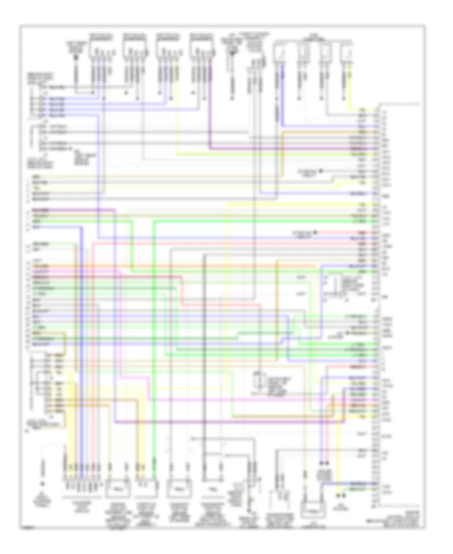
1.8L, Engine Performance Wiring Diagram, 4WD Except XRS (1 of 3) for Toyota Matrix 2006
List of elements for 1.8L, Engine Performance Wiring Diagram, 4WD Except XRS (1 of 3) for Toyota Matrix 2006:
- (left front suspension tower) eb
- (left rear side of engine)
- 22-31 (not used)
- A/c system
- Acc
- B13
- B21
- Batt
- Bh (at left quarter panel)
- Braid
- C/opn relay
- C12
- C16 cruise control ecu (behind left side of dash)
- Center j/b (behind left side of dash)
- Center j/b (left side of dash)
- Cooling fans system
- Cruise control system
- D19
- E03
- Ec (rear left side of cyl head)
- Ect
- Efi fuse 15a
- Efi relay
- Eknk
- Els
- Els2
- Engine control module (behind right side of dash, below glove box)
- Engine room j/b (left side of engine compt)
- Eom
- Evp
- Exterior lights system
- F/ps
- Fan
- Fuel pump
- Heated oxygen sensor, bank 1 sensor 1 (on exhaust pipe, right rear of eng)
- Heated oxygen sensor, bank 1 sensor 2 (on exhaust pipe, under center of vehicle)
- Hot at all times
- Hot w/ def relay energized
- Ht1a
- Ht1b
- Ie (behind left side of dash)
- Ignition switch
- Ignsw
- Instrument panel j/b (behind left side of dash)
- J/c 2
- J/c 3 behind right side dash)
- J/c 5, j/c 6 (behind right side of dash)
- J/c 7 (behind right kick panel)
- Knk1
- Lock
- M-htr/ def i-up fuse 10a
- Mpmp
- Nt+
- Nt-
- Od1
- Ox1a
- Pnk
- Power steering oil pressure switch (right rear of eng compt)
- Psw
- Ptnk
- Run
- Slt+
- Slt-
- Start
- Tho
- Vehicle speed sensor (electronically controlled transmission) (top of transaxle)
- Wfse
1.8L, Engine Performance Wiring Diagram, 4WD Except XRS (2 of 3) for Toyota Matrix 2006
List of elements for 1.8L, Engine Performance Wiring Diagram, 4WD Except XRS (2 of 3) for Toyota Matrix 2006:
- (below left side of dash) data link connector 3
- (left front of engine) camshaft timing oil control valve (vvt)
- B20
- B22
- Braid
- C11
- C13
- C14
- C18
- C20
- Center j/b (behind left side of dash)
- Combination meter
- E2g
- Ec (rear left side of cyl head)
- Electronically controlled transmission solenoid (on top of transaxle)
- Evap vsv (left rear of engine compt)
- Gauge fuse 10a
- Hot at all times
- Hot in on or start
- Instrument panel j/b (behind left side of dash)
- Interior lights system
- J/c 3 (behind right side of dash)
- J/c 3, j/c 4 (behind right side of dash)
- J/c 7 (behind right kick panel)
- Knock sensor (bank 1) (left side of eng)
- Malfunction ind
- Mass air flow meter (at left rear of engine compartment in air intake duck)
- O/d main switch
- O/d off indicator
- Park/neutral position switch (left side of transaxle)
- Pnk
- Right j/b (behind upper right side of dash)
- Sil
- Stop fuse 15a
- Stop light switch (on bracket, above brake pedal)
- System brakes anti-lock
- Tha
- Wfse
1.8L, Engine Performance Wiring Diagram, 4WD Except XRS (3 of 3) for Toyota Matrix 2006
List of elements for 1.8L, Engine Performance Wiring Diagram, 4WD Except XRS (3 of 3) for Toyota Matrix 2006:
- (behind right side of dash) j/c 5, j/c 6
- (left rear side of engine) ed
- (on instrument panel j/b) noise filter
- (rear left side of cyl head)
- (throttle body assembly) idle air control valve
- A/c system
- A/c thermistor
- A/cs
- Acld
- Acmg
- Bi (right quarter panel)
- Braid a
- Camshaft position sensor (left rear of engine)
- Canister pump module
- Crankshaft position sensor (lower left front of eng, near crankshaft)
- Cruise control system
- Duty
- E01
- E02
- Ed (left rear side of engine)
- Efii
- Efio
- Engine control module (behind right side of dash, below glove box)
- Engine coolant temperature sensor (rear of eng, on coolant outlet)
- Evg
- Fuel injectors
- Gnd
- Idlo
- Igf
- Ignition coil & igniter 1
- Ignition coil & igniter 2
- Ignition coil & igniter 3
- Ignition coil & igniter 4
- Igt
- Igt1
- Igt2
- Igt3
- Igt4
- Imi
- Imo
- Instrument panel j/b (behind left side of dash)
- J/c 3, j/c 4 (behind right side of dash)
- J/c 5, j/c 6 (behind right side of dash)
- J/c 5, j/c 6 (right side dash)
- J3 a
- K10
- Mpmp
- Mrel
- Ne+
- Ne-
- Nsw
- Ocv+
- Ocv-
- Od1
- Odlp
- Odms
- Ox1b
- Red
- Rsd
- Sgnd
- Sil
- Spd
- Sta
- Starting circuit
- Stp
- Tach
- Tha
- Thr
- Throttle position sensor (on throttle body assembly)
- Thw
- Thwo
- Transponder key computer (behind left side of dash)
- Vcc
- Visc
- Vout
- Vpmp
- Vta
1.8L, Engine Performance Wiring Diagram, XRS (1 of 3) for Toyota Matrix 2006
List of elements for 1.8L, Engine Performance Wiring Diagram, XRS (1 of 3) for Toyota Matrix 2006:
- (2005 models only)
- (left front suspension tower) eb
- 22-31 (not used)
- A/c system
- A/cs
- Acc
- Air pmp fuse 50a
- Air pump motor (left front of engine compt)
- Air pump relay (left front of engine compt)
- Airp
- Airv
- Batt
- Bh (at left quarterpanel)
- Braid
- C/opn relay
- C12
- Center j/b (behind center of dash)
- Cooling fans system
- D19
- E03
- Ec (rear of engine)
- Ed (rear of engine)
- Efi fuse 15a
- Efi relay
- Ej (at left front of eng compt)
- Eknk
- Els
- Els2
- Engine control module (behind right side of dash)
- Engine room j/b (left side of engine compt)
- Exterior lights system
- F/ps
- Fan
- Fuel pump
- Heated oxygen sensor (bank 1 sensor 2) (in exhaust pipe, after converter)
- Heated oxygen sensor 1 (bank 1 sensor 1) (in exhaust manifold)
- Hot at all times
- Hot w/ def relay energized
- Ht1a
- Ht1b
- I13
- Ignition switch
- Igsw
- Instrument panel j/b (behind left side of dash)
- J/c 3 (right side of dash)
- J/c 7 (behind right kick panel)
- Knk1
- Lock
- M-htr/ def i-up fuse 10a
- Me01
- Mpmp
- Ox1a
- Pnk
- Power steering oil pressure switch (right rear of engine compt)
- Ppmp
- Prg
- Psw
- Red
- Run
- Start
- Vvl+
- Vvl-
- Wfse
1.8L, Engine Performance Wiring Diagram, XRS (2 of 3) for Toyota Matrix 2006
List of elements for 1.8L, Engine Performance Wiring Diagram, XRS (2 of 3) for Toyota Matrix 2006:
- (2005)
- (2006)
- (below left side of dash) data link connector 3
- (instrument panel harn, right side of dash)
- (left front of engine) camshaft timing oil control valve (vvt)
- (rear of engine) camshaft timing oil control valve (vvtl)
- Air pump pressure sensor (at front of engine)
- Bh (left quarter- panel)
- Braid
- C11
- C13
- C14
- Center j/b (behind center of dash)
- Combination meter
- E2g
- Ec (rear of engine)
- Efii
- Efio
- Evap vsv (left rear of engine compt)
- Hot at all times
- I12
- Instrument panel j/b (behind left side of dash)
- J/c 3, j/c 4 (right side of dash)
- J9 j/c 8, j/c 9 (left rear of vehicle) j8
- Knock sensor (bank 1) (left side of eng)
- Leak detection pump assembly
- Malfunction indicator lamp
- Mass air flow meter (left rear of engine compt)
- Mgnd
- Mtrb
- Oil pressure switch (vvtl) (lower left side of engine)
- Pim
- Pnk
- Red
- Right j/b (behind upper right side of dash)
- Sgnd
- Sil
- Stop fuse 15a
- Stoplamp switch (on brake pedal support bracket)
- Tha
- Transponder key computer (left side of dash)
- Vcc
- Vgnd
- Vlvb
- Vout
- Wfse
1.8L, Engine Performance Wiring Diagram, XRS (3 of 3) for Toyota Matrix 2006
List of elements for 1.8L, Engine Performance Wiring Diagram, XRS (3 of 3) for Toyota Matrix 2006:
- (instrument panel harn, right side of dash)
- (rear of engine)
- (rear of engine) ed
- (rear of engine) noise filter
- (right side dash)
- (right side dash) j/c 5, j/c 6
- (right side of dash) j/c 5, j/c 6
- (throttle body) idle air control valve
- A/c system
- A/c thermistor
- Acis vsv (front of air cleaner assembly)
- Acld
- Aclv
- Acmg
- Aip
- Air pump (vsv) (left rear of engine)
- Braid
- Camshaft position sensor (left rear of engine)
- Crankshaft position sensor (lower left front of engine)
- Cruise control system
- Duty
- E01
- E02
- E3 (engine harn, rear of engine)
- Ed (rear of engine)
- Engine control module (behind right side of dash)
- Engine coolant temperature sensor (rear of engine)
- Evg
- Fuel injectors
- G22+
- Gnd
- I12
- Idlo
- Igf
- Ignition coil & igniter 1
- Ignition coil & igniter 2
- Ignition coil & igniter 3
- Ignition coil & igniter 4
- Igt
- Igt1
- Igt2
- Igt3
- Igt4
- Imi
- Imo
- J/c 3, j/c 4 (right side of dash)
- J/c 5, j/c 6
- Mrel
- Ne+
- Ne-
- Oc1+
- Oc1-
- Osw
- Ox1b
- Red
- Rso
- Sil
- Spd
- Sta
- Starting circuit
- Stp
- Tach
- Tha
- The
- Throttle position sensor (rear of throttle body)
- Thw
- Thwo
- Visc
- Vpmp
- Vta
EXTERIOR LIGHTS
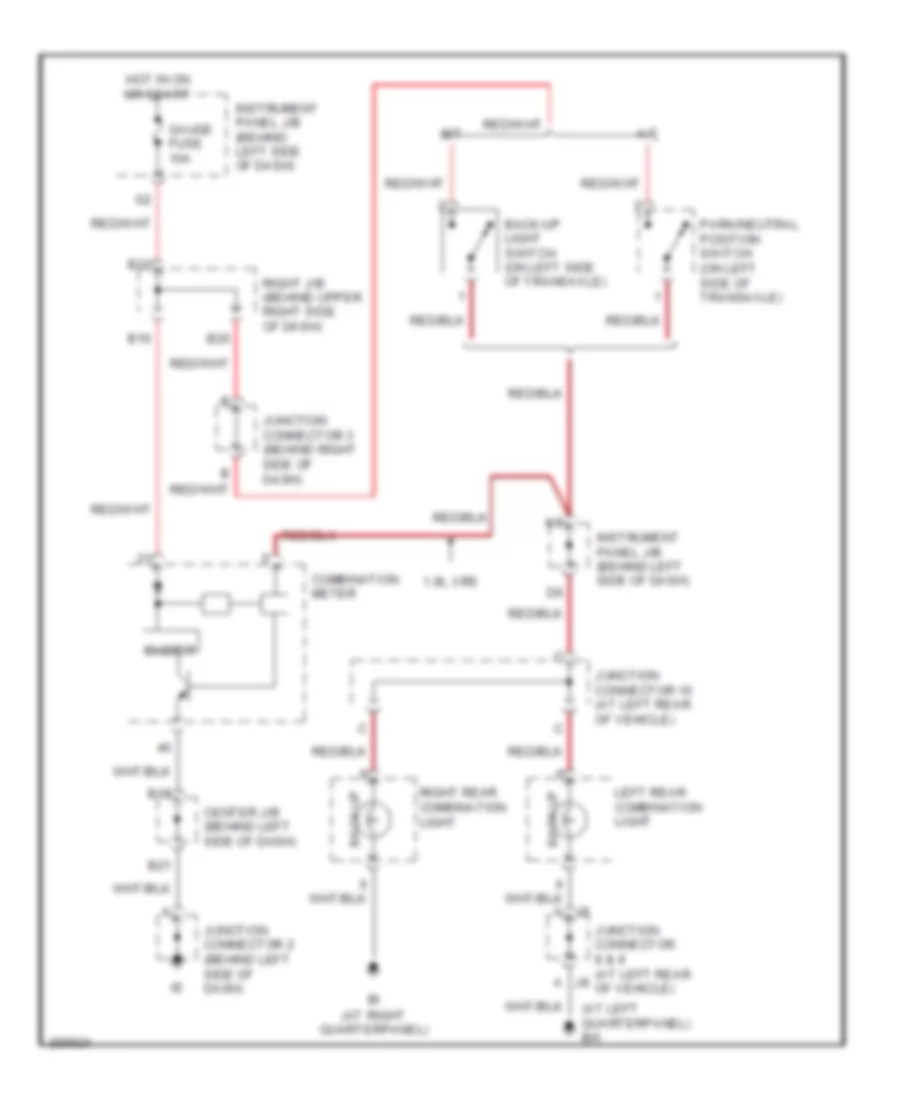
Back-up Lamps Wiring Diagram for Toyota Matrix 2006
List of elements for Back-up Lamps Wiring Diagram for Toyota Matrix 2006:
- (at left quarterpanel) bh
- (at right quarterpanel)
- 1.8l xrs
- A/t
- B16
- B18
- B20
- B21
- B22
- Back-up
- Back-up light switch (on left side of transaxle)
- Buzzer
- Center j/b (behind left side of dash)
- Combination meter
- Gauge fuse 10a
- Hot in on or start
- Instrument panel j/b (behind left side of dash)
- Instrument panel j/b (behind left side of dash)
- Junction connector 10 (at left rear of vehicle)
- Junction connector 2 (behind left side of dash)
- Junction connector 3 (behind right side of dash)
- Junction connector 8 & 9 (at left rear j8 of vehicle)
- Left rear combination light
- M/t
- Park/neutral position switch (on left side of transaxle)
- Right j/b (behind upper right side of dash)
- Right rear combination light
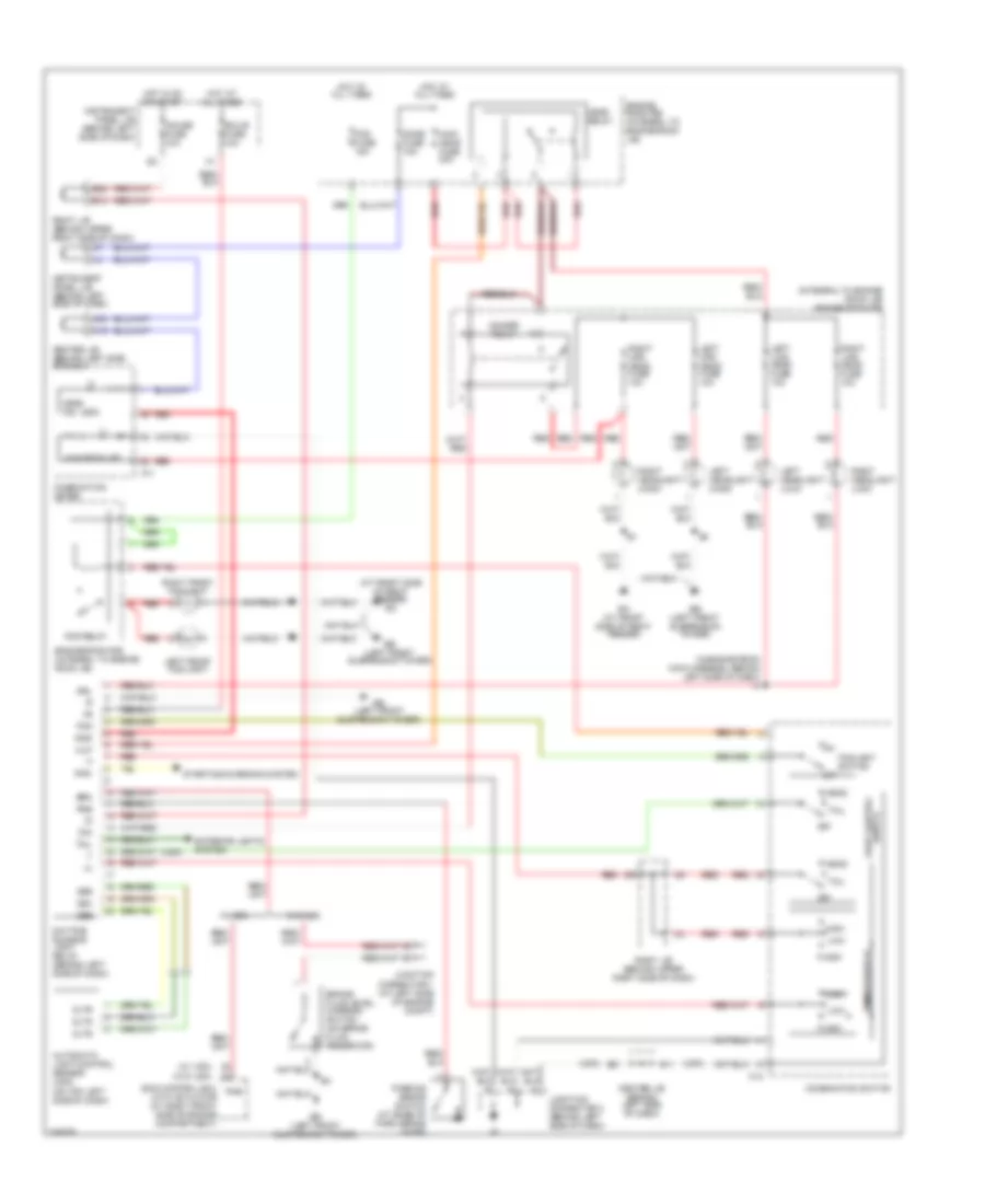
Exterior Lamps Wiring Diagram for Toyota Matrix 2006
List of elements for Exterior Lamps Wiring Diagram for Toyota Matrix 2006:
- & 1zz-fe 4wd w/o cruise control
- & 1zz-fe except 4wd w/o cruise control
- (at left rear of vehicle) junction connector 8 & 9
- (at left side of engine compartment)
- (behind left
- (canada)
- (on bracket, above brake pedal)
- (usa)
- (usa) tail relay
- 2zz-ge w/ cruise control
- 2zz-ge w/o cruise control
- A11
- A21
- B11
- B15
- B17
- B18
- B21
- B22
- Bh (at left quarterpanel)
- Bi (at right quarterpanel)
- C14
- Center j/b
- Combination
- Combination meter
- Control
- D12
- D17
- Daytime running light relay (behind left side of dash)
- Ea (at front side of right fender)
- Eb (on left front suspension tower)
- Ehw
- Engine room r/b (integral to engine room j/b)
- Gauge fuse 10a
- Gnd
- H11
- H12
- H13
- Hazard fuse 10a
- Hazard switch
- Head
- High
- Hot at all times
- Hot in on or start
- Instrument panel j/b (behind left side of dash)
- Interior lights system
- J/c
- J/c 8 & 9 (at left rear of vehicle)
- J/c 8 (at left rear of vehicle)
- Junction connector 11 (at left side of back door)
- Junction connector 2 (behind left side of dash)
- Junction connector 7 (at right kick panel)
- Left front combination light
- Left license plate light
- Left rear combination light
- Light
- Mounted
- Off
- Park
- Right front combination light
- Right j/b (behind upper right side of dash)
- Right license plate light
- Right r/b (integral to right j/b)
- Right rear combination light
- Side of dash)
- Stop
- Stop fuse 15a
- Stop light switch
- Stoplight
- Switch
- Tail
- Tail fuse 15a
- Turn
- Turn sig
- Turn signal flasher relay (behind left side of dash, on instrument panel j/b)
- Turn signal ind
- W/ wireless door lock
- W/o wireless door lock
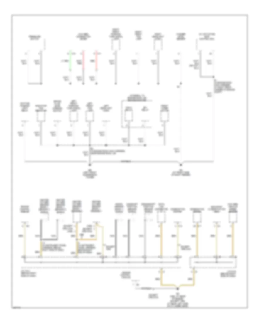
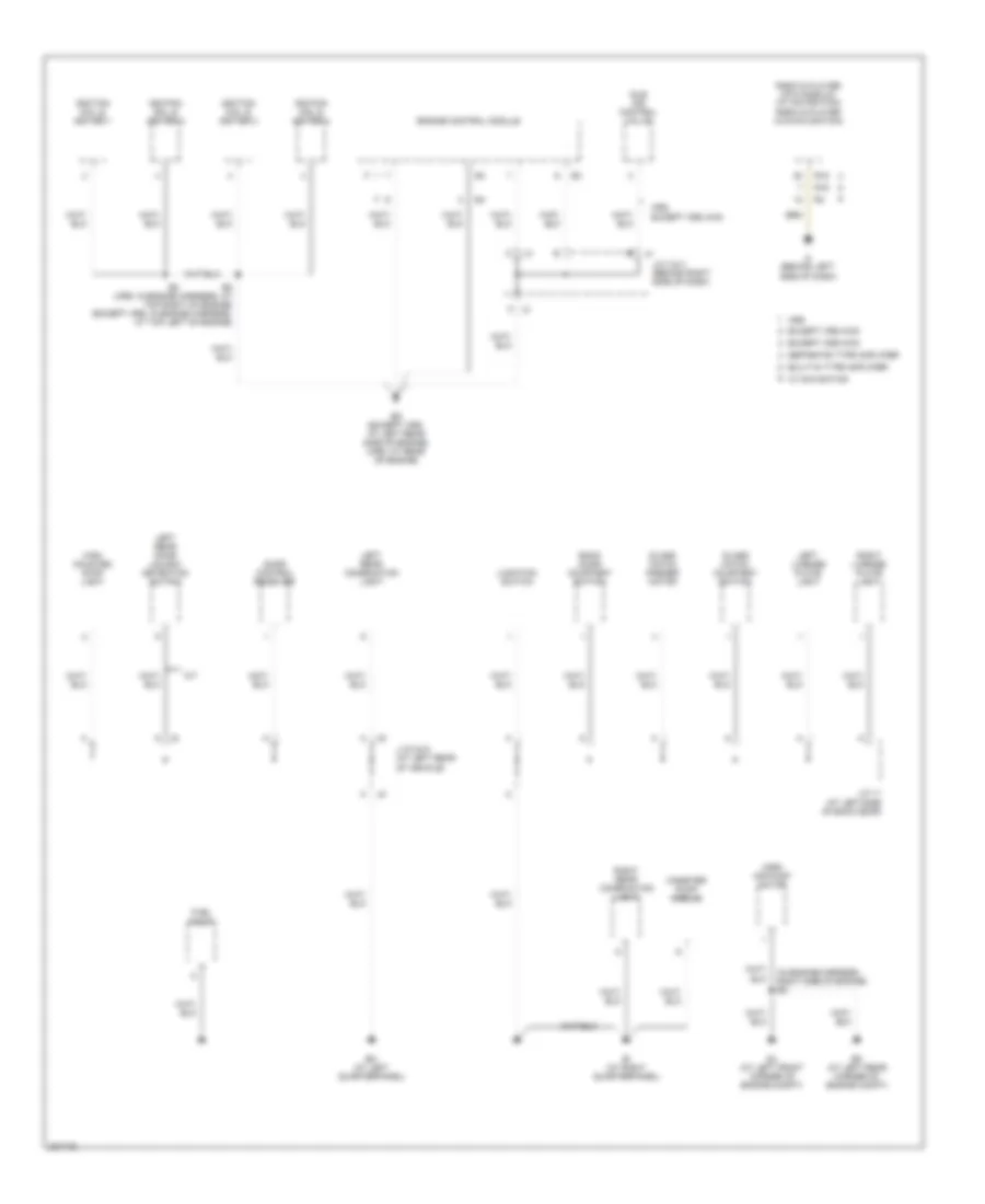
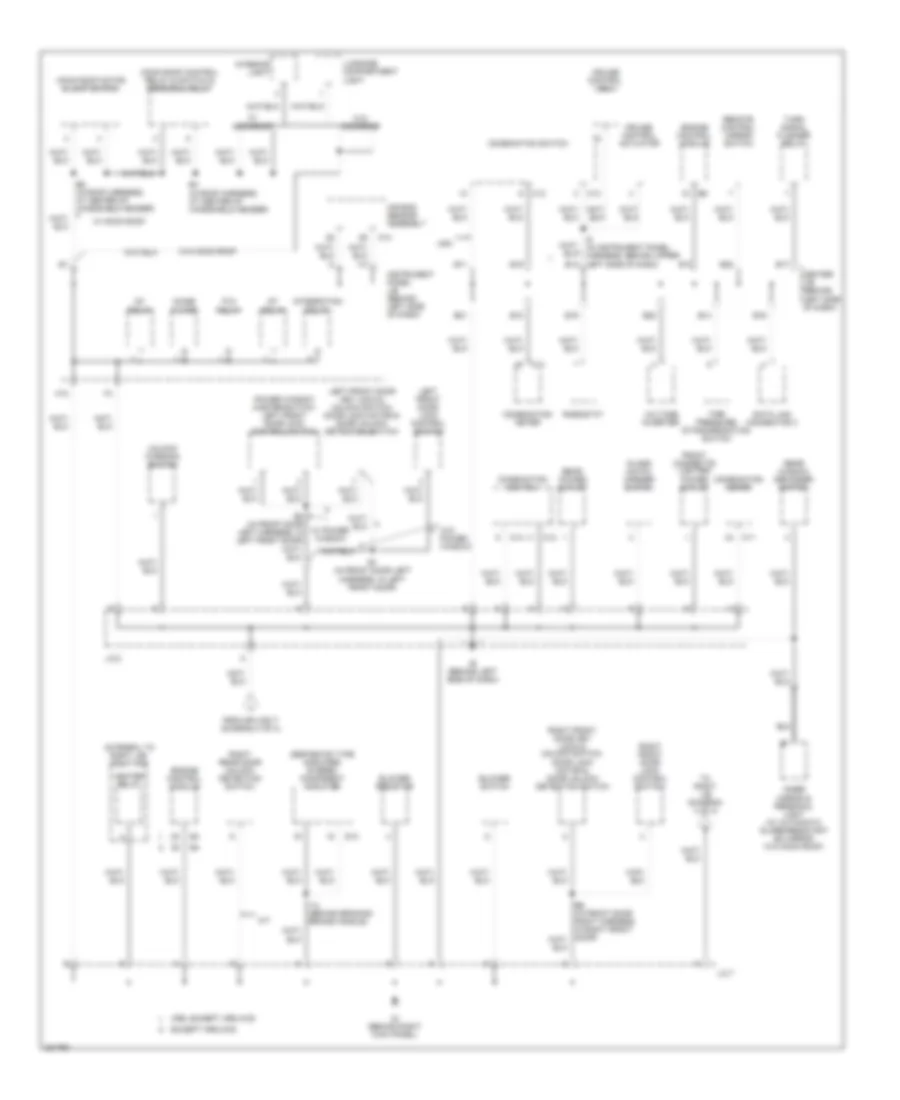
GROUND DISTRIBUTION
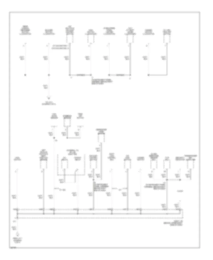
Ground Distribution Wiring Diagram (1 of 4) for Toyota Matrix 2006
List of elements for Ground Distribution Wiring Diagram (1 of 4) for Toyota Matrix 2006:
- (except xrs 4wd)
- (integral to engine room j/b) engine room r/b
- (w/ actuator) skid control ecu
- (w/o abs) combination meter
- (w/o abs) vehicle speed sensor
- (xrs)
- A j3
- Brake fluid level warning switch
- C j5
- C11
- C13
- C18
- Camshaft position sensor shield
- Combination meter
- Combination switch
- Crankshaft position sensor shield
- Data link connector
- Daytime running light relay
- E1 (in engine room main harness, at right front corner of engine compt)
- E4 (in engine room main harness, near engine room j/b)
- Ea (at front side of right fender)
- Eb (left front suspension tower)
- Ec (xrs: at rear of engine) (except xrs: at rear left side of cylinder head)
- Efi relay
- Engine control module
- Except xrs
- Except xrs 2wd
- Fan 2 relay
- Front wiper motor
- Heated oxygen sensor (bank 1, sensor 1)
- Heated oxygen sensor (bank 1, sensor 1) shield
- Heated oxygen sensor (bank 1, sensor 2)
- Heated oxygen sensor (bank 1, sensor 2) shield
- I13 (in instrument panel harness, behind right side of dash)
- J/c 3 & 4 (behind right side of dash)
- J/c 5 & 6 (behind right side of dash)
- Knock sensor (bank 1) shield
- Left front fog lamp
- Left front parking/ turn signal lamp
- Left headlight (high)
- Nca
- Occupant classification ecu
- Pressure switch
- Radiator fan resistor
- Red
- Right front fog lamp
- Right front parking/ turn signal lamp
- Right headlight (high)
- Washer level sensor
- Xrs
Ground Distribution Wiring Diagram (2 of 4) for Toyota Matrix 2006
List of elements for Ground Distribution Wiring Diagram (2 of 4) for Toyota Matrix 2006:
- (in engine harness, right side of engine) e5
- (xrs) air pump motor
- A/t
- Back door courtesy switch
- Bh (at left quarterpanel)
- Bi (at right quarterpanel)
- Built-in type amplifier
- Canister pump module
- Door control receiver
- E2 (xrs: in engine harness, at top right of engine) (except xrs: in engine harness, at top left of engine)
- Ed (except xrs: at left rear side of engine) (xrs: at rear of engine)
- Ej (at left front corner of engine compt)
- Ek (at left rear corner of engine compt)
- Engine control module
- Except xrs 2wd
- Except xrs 4wd
- Fuel pump
- Glass hatch courtesy switch
- Glass hatch opener motor
- High mounted stop light
- Idle air control valve
- If (behind left side of dash)
- Ignition coil & igniter 1
- Ignition coil & igniter 2
- Ignition coil & igniter 3
- Ignition coil & igniter 4
- J/c 11 (at left side of back door)
- J/c 3 & 4 (behind right side of dash)
- J/c 8 & 9 (at left rear of vehicle)
- Junction switch
- Left license plate light
- Left rear combination light
- Left rear door unlock detection switch
- R16
- Radio & player with display (w/ navigation) radio & player (w/o navigation)
- Right license plate light
- Right rear combination light
- Separate type amplifier
- W/ navigation
- Xrs
- Xrs, except xrs 4wd
Ground Distribution Wiring Diagram (3 of 4) for Toyota Matrix 2006
List of elements for Ground Distribution Wiring Diagram (3 of 4) for Toyota Matrix 2006:
- (integral to right j/b) right r/b
- (separate type amplifier) stereo component amplifier
- A/t
- A13
- Air bag sensor assembly
- B1 (in front door left harness, in left front door)
- B11
- B13
- B14
- B15
- B16
- B17
- B18
- B19
- B2 (in front door left harness, in left front door)
- B20
- B21
- B22
- B4 (in roof harness, at center of windshield header)
- B5 (in roof harness, at center of windshield header)
- Blower resistor
- Blower switch
- C11
- C12
- C13
- C14
- Center j/b (behind left side of dash)
- Combination meter
- Combination switch
- Cruise control actuator
- Cruise control ecu
- Data link connector 3
- Engine control module
- Except xrs 2wd
- From splice i7 (diagram 4 of 4)
- Front cigarette lighter/ power outlet
- Glass hatch opener switch
- H10
- Heater relay
- I10
- I14 (behind braking brake handle)
- I5 (in instrument panel harness, behind upper left side of dash) b12
- Ie (behind left side of dash)
- Ig (behind right kick panel)
- Ig1 relay
- Inner mirror & personal light (w/ automatic glare-resistant ec mirror w/o moon roof)
- Instrument panel j/b (behind left side of dash)
- Integration relay
- Interior light
- J/c 2
- J/c 7
- Left front door key lock & unlock switch, door lock motor & door unlock detection switch
- Left front door lock control switch
- Luggage compartment light
- Moon roof control relay & switch & personal relay
- Moon roof motor & limit switch
- Noise filter
- P/w relay
- Power window master switch/ left front door lock control switch
- Rear power outlet
- Rear window defogger switch
- Remote control mirror switch
- Rheostat
- Right front door key lock & unlock switch, door lock motor & door unlock detection switch
- Right front door lock control switch
- Right rear door unlock detection switch
- S13
- St relay
- Tire pressure standardization switch
- To right j/b (diagram 4 of 4)
- Turn signal flasher relay
- Unlock warning switch
- Usa
- Voltage inverter
- W/ moon roof
- W/ moonroof
- W/ power window
- W/o moon roof
- W/o moonroof
- W/o power window
- Xrs, except xrs 4wd
Ground Distribution Wiring Diagram (4 of 4) for Toyota Matrix 2006
List of elements for Ground Distribution Wiring Diagram (4 of 4) for Toyota Matrix 2006:
- (a/t) a/t shift lever illumination
- (if equipped) cigar lighter illumination
- (integral to rh j/b) right r/b
- (w/ navigation)
- (w/ vsc) trac off switch
- (w/o navigation)
- A/c switch & air inlet control switch
- A/t
- A11
- A12
- A13
- A15
- A16
- A17
- A18
- A19
- A20
- A21
- A22
- Air inlet control switch
- Blower switch illumination
- Clock
- Defroster mode switch
- From j/c 7 (diagram 3 of 4)
- Glass breakage sensor ecu
- Hazard switch
- Hazard switch illumination
- I10 (in instrument panel harness, behind right end of dash)
- I19
- I7 (in instrument panel harness, behind right side of dash)
- I9 (in instrument panel harness, behind right end of dash)
- Inv relay
- Left buckle switch & seat position sensor
- Main switch
- Main switch illumination
- O/d main switch
- P-point relay
- Rear window defogger switch illumination
- Right j/b (behind upper right side of dash)
- Security indicator
- Shift lock control ecu
- Steering sensor
- To j/c 2 (diagram 3 of 4)
- Trac off switch
- Transponder key computer
- Tvip ecu
- W/ vsc
- Yaw rate sensor
HEADLIGHTS
Headlights Wiring Diagram for Toyota Matrix 2006
List of elements for Headlights Wiring Diagram for Toyota Matrix 2006:
- (at front side of right fender) ea
- (in engine room main harness, behind left side of dash) i4
- (integral to engine room j/b) engine room r/b
- (on top left side of dash)
- (usa)
- (w/ vsc)
- (w/o vsc)
- Automatic light control sensor (usa)
- B11
- B12
- B21
- B22
- Brake fluid level warning switch (on brake fluid reservoir)
- Brk
- C11
- C12
- C19
- C20
- Center j/b (behind left side of dash)
- Chg-
- Cltb
- Clte
- Clts
- Combination meter
- Combination switch
- Csb
- Cse
- Cso
- Daytime running light relay (behind left side of dash)
- Dim
- Dimmer relay
- Dimmer switch
- Dome fuse 15a
- Drl
- Ea (at front side of right fender)
- Eb (left front suspension tower)
- Ecu-b fuse 10a
- Engine room r/b (integral to engine room j/b)
- Exterior lights system
- Flash
- Fog
- Fog fuse 15a
- Fog relay
- Foglight switch
- Gauge fuse 10a
- H-lp
- Head
- Head ind
- Head relay
- High
- High beam ind
- Hind
- Hot at all times
- Hot in on or start
- Instrument panel j/b (behind left side of dash)
- Junction connector 1 (at left side of engine compt)
- Junction connector 2 (behind left side of dash)
- Left front fog light
- Left headlight (high)
- Left headlight (low)
- Left lwr head fuse 10a
- Left upr head fuse 10a
- Light control switch
- Low
- Main head fuse 40a
- Off
- Parking brake switch (at base of park brake lever)
- Pkb
- Red
- Right front fog light
- Right headlight (high)
- Right headlight (low)
- Right j/b (behind upper right side of dash)
- Right lwr head fuse 10a
- Right upr head fuse 10a
- Skid control ecu with actuator (at right front side of engine compartment)
- Starting/charging system
- Tail
- W/ abs
- W/o abs
HORN
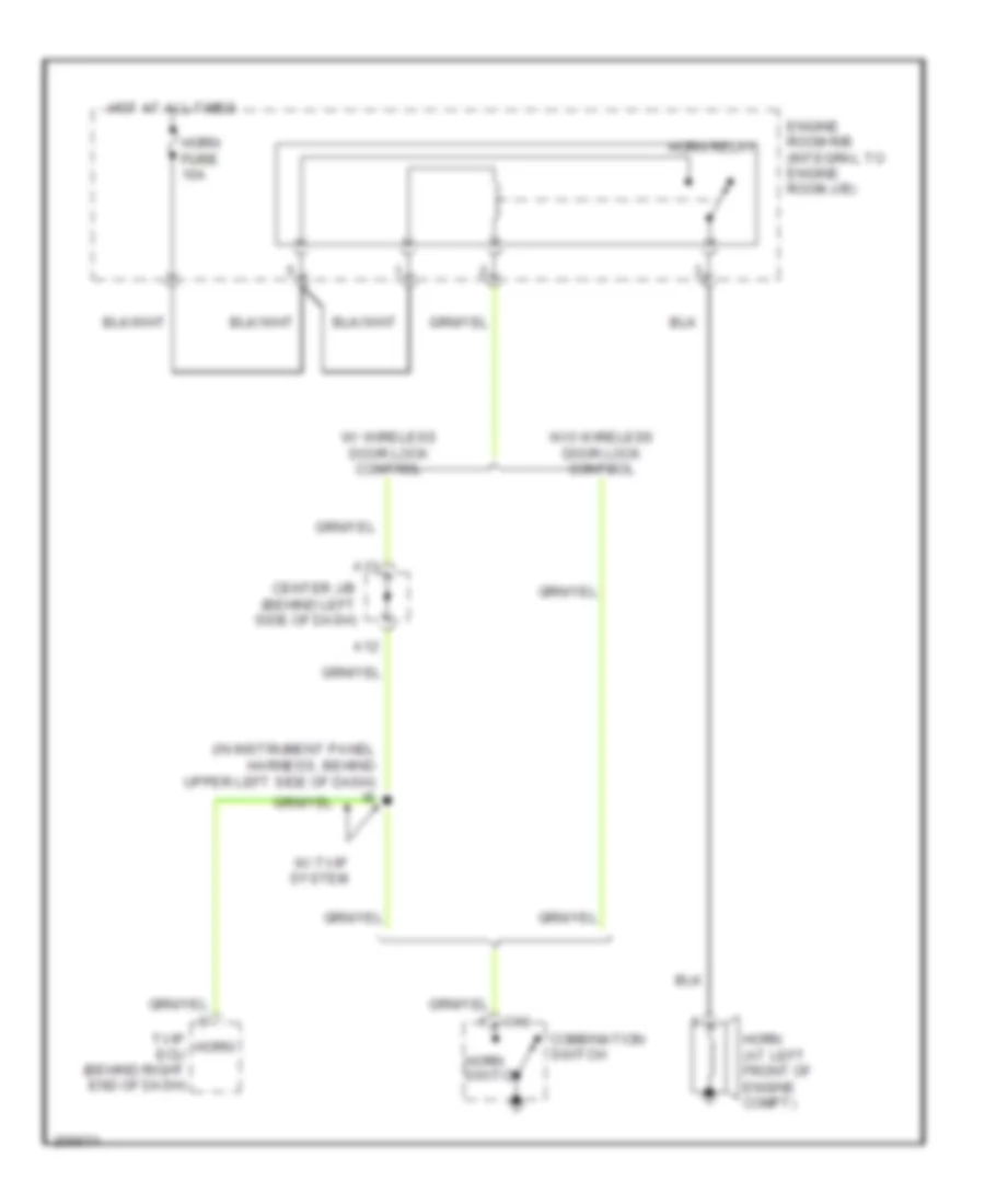
Horn Wiring Diagram for Toyota Matrix 2006
List of elements for Horn Wiring Diagram for Toyota Matrix 2006:
- (in instrument panel harness, behind upper left side of dash) i6
- A12
- A13
- C13
- Center j/b (behind left side of dash)
- Combination switch
- Engine room r/b (integral to engine room j/b)
- Horn (at left front of engine compt)
- Horn fuse fuse 10a
- Horn relay
- Horn switch
- Hot at all times
- Tvip horn ecu (behind right end of dash)
- W/ tvip system
- W/ wireless door lock control
- W/o wireless door lock control
INSTRUMENT CLUSTER
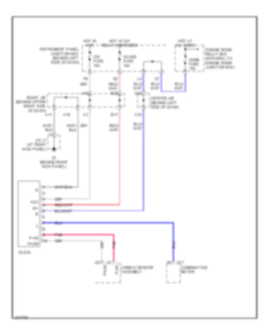
Clock Wiring Diagram for Toyota Matrix 2006
List of elements for Clock Wiring Diagram for Toyota Matrix 2006:
- A10
- A11
- A18
- Acc
- Airbag sensor assembly
- B11
- B22
- C11
- C16
- C20
- Center j/b (behind left side of dash)
- Cig fuse 15a
- Clock
- Combination meter
- Dome fuse 15a
- Engine room relay box (integral to engine room junction box)
- Gauge fuse 10a
- Hot at all times
- Hot in acc
- Hot w/ ig1 relay energized
- Ig (behind right kick panel)
- Ig+
- Instrument panel junction box (behind left side of dash)
- J/c j7 (at right kick panel)
- P-ab
- Paon
- Pnk
- Right j/b (behind upper right side of dash)
Instrument Cluster Wiring Diagram for Toyota Matrix 2006
List of elements for Instrument Cluster Wiring Diagram for Toyota Matrix 2006:
- (at front side of right fender)
- (behind right side of dash) junction connector 3 & 4
- (except xrs:
- (except xrs: at rear left side of cylinder head) (xrs: at rear of engine) ec
- (in instrument panel harness, behind upper left side of dash)
- (on top of transaxle)
- (w/o abs) vehicle speed sensor (combination meter)
- (xrs: on left front suspension tower)
- A10
- A11
- A12
- A14
- A15
- A16
- A17
- A18
- A19
- A20
- A21
- A22
- A23
- A24
- A25
- A26
- A27
- A29
- A30
- A31
- A32
- A33
- A34
- A35
- A36
- A37
- A38
- A39
- A40
- Abs ind
- Ambient temperature sensor (at middle front of engine compt)
- Anti-lock brakes system
- Anti-lock brakes system engine controls system
- At left front suspension tower)
- B16
- B18
- B20
- B21
- B22
- Brake fluid level warning switch (on brake fluid reservoir)
- Brake ind
- Brk
- Buzzer
- C11
- C18
- C19
- C20
- Center j/b (behind left side of dash)
- Charge ind
- Clock circuit (instrument cluster system) warning system
- Combination meter
- Cruise control system
- Cruise ind
- Daytime running light relay (behind left side of dash)
- Dome fuse 15a
- Door ind
- Ea (at front side of right fender)
- Engine controls system
- Engine room relay box (integral to engine room junction block)
- Exterior lights system
- Fuel gauge
- Fuel ind
- Fuel pump & fuel sender (in fuel tank)
- Gauge fuse 10a
- Head ind
- Head rh upr fuse 10a
- Headlights system
- High beam ind
- Hot at all times
- Hot in on or start
- Hot w/ dimmer relay energized
- Illumination
- Ind
- Instrument panel junction block (behind left side of dash)
- Interior lights system
- Junction connector 1 (at left side of engine compt)
- Junction connector 2 (behind left side of dash)
- Junction connector 5 & 6 (behind right side of dash)
- Left turn ind
- Maint reqd ind
- Malfunction ind
- O/d off ind
- Odo/trip lcd
- Oil pressure ind
- Oil pressure switch (except xrs: on lower left side of engine) (xrs: at right rear of engine)
- Out side temperature lcd
- Parking brake switch (at base of park brake lever)
- Pkb
- Red
- Right j/b (behind upper right side of dash)
- Right turn ind
- Seat belt ind
- Slip ind
- Speedometer
- Srs ind
- Starting/charging system
- Tachometer
- Temperature
- Tire pressure
- Vsc
- W/ abs
- W/o abs
- Warning system
- Washer level ind
- Wiper/washer system
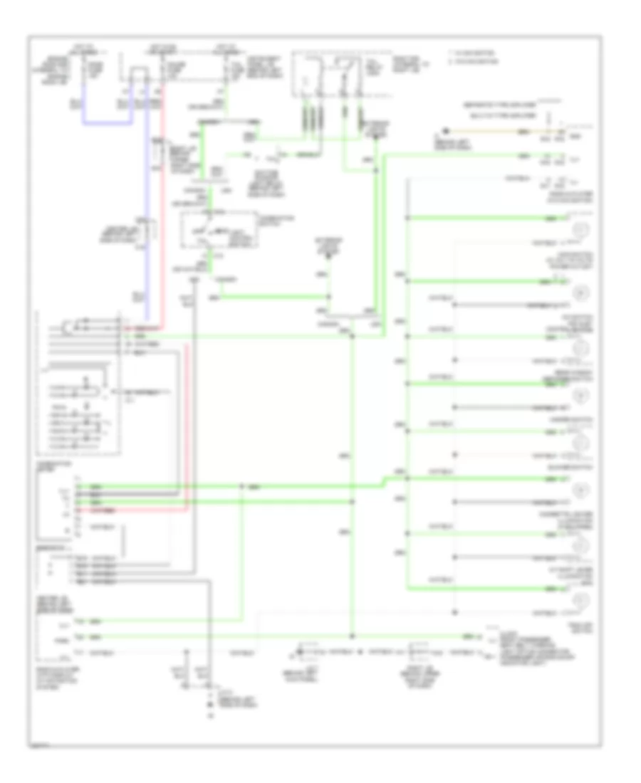
INTERIOR LIGHTS
Courtesy Lamps Wiring Diagram for Toyota Matrix 2006
List of elements for Courtesy Lamps Wiring Diagram for Toyota Matrix 2006:
- (at center of back door) diode (door courtesy)
- (at left side of back door)
- B10
- Back door courtesy switch
- Bh (at left quarterpanel)
- C11
- C19
- C20
- Center j/b (behind left side of dash)
- Center j/b (w/o door lock control) (behind left side of dash)
- Combination meter
- D14
- D15
- D16
- Dcty
- Dome fuse 15a
- Door
- Door fuse 25a
- Door ind
- Engine room r/b (integral to engine room j/b)
- Gauge fuse 10a
- Glass hatch courtesy switch (at center of back door)
- Gnd
- H10
- Hot at all times
- Hot in on or start
- I12
- Ie (behind left side of dash)
- Instrument panel j/b (behind left side of dash)
- Integration relay (on instrument panel j/b)
- Interior light
- J/c 11
- J/c 2 (behind left side of dash)
- J/c 7 (at right kick panel)
- Left front door courtesy switch
- Left rear door courtesy switch (forward of left rear wheelwell)
- Lp 2
- Luggage compartment light
- Off
- P-dr
- Pcty
- Personal light
- Red
- Right front door courtesy switch
- Right rear door courtesy switch (forward of right rear wheelwell)
- W/ automatic glare- resistant ec mirror
- W/ door lock control
- W/ moon roof
- W/o automatic glare- resistant ec mirror
- W/o door lock control
- W/o moon roof
- Wiper/washer system
Instrument Illumination Wiring Diagram for Toyota Matrix 2006
List of elements for Instrument Illumination Wiring Diagram for Toyota Matrix 2006:
- (a/t)
- (behind left side of dash)
- (if equipped)
- A/c switch air inlet control switch
- A/t shift lever
- A11
- A18
- B11
- B16
- B18
- B19
- B21
- B22
- Blower switch
- Built-in type amplifier
- C11
- C12
- C19
- C20
- Canada
- Center j/b (behind left side of dash)
- Cigarette lighter
- Clock front passenger ill- seat belt warning light option connector (passenger air bag on-off indicator light)
- Combination meter
- Combination switch
- Daytime running light relay (behind left side of dash)
- Dome fuse 15a
- Engine room r/b (integral to engine room j/b)
- Exterior lights system
- Gauge fuse 10a
- Gnd
- Hazard switch
- Head
- Hot at all times
- Hot in on or start
- If (behind left side of dash)
- Ill+
- Ill-
- Illumination
- Instrument panel j/b (behind left end of dash)
- J/c 2
- J/c 7 (behind left kick panel)
- Light control switch
- Main switch (w/ a/c 115 volts power outlet)
- Off
- Park
- R16
- R17
- Radio & player (w/o navigation)
- Radio & player with display (w/ navigation
- Rear window defogger switch
- Rheostat
- Right j/b (behind upper right side of dash)
- Right j/b behind upper right side of dash)
- Right r/b (integral to right j/b)
- Separate type amplifier
- System)
- Tail
- Tail fuse 15a
- Tail relay (usa)
- Trac off switch
- Usa
- W/ navigation
- W/o navigation
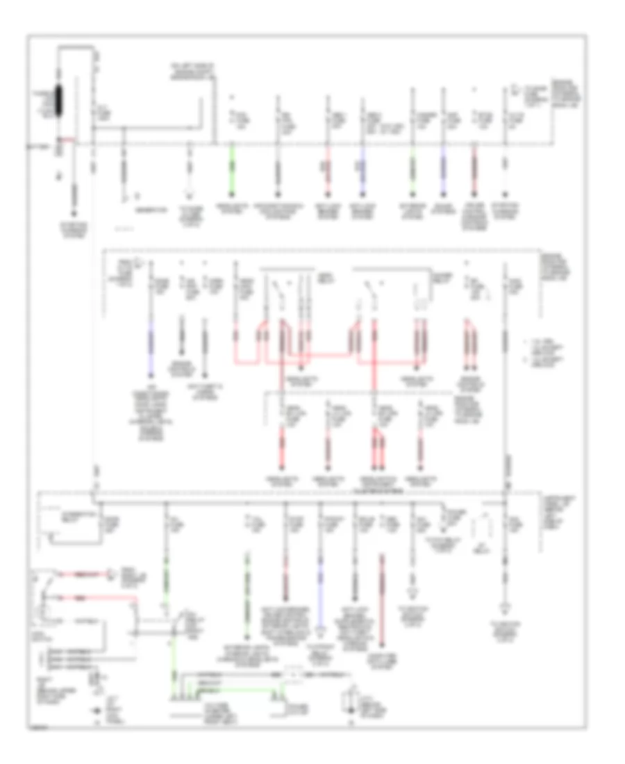
POWER DISTRIBUTION
Power Distribution Wiring Diagram (1 of 2) for Toyota Matrix 2006
List of elements for Power Distribution Wiring Diagram (1 of 2) for Toyota Matrix 2006:
- (on left side of engine compt) engine room j/b
- (w/o vsc) (w/ vsc)
- 1.8l except xrs 2wd
- 1.8l xrs, 1.8l except xrs 4wd
- A11
- A12
- A13
- Abs 1 fuse 30a
- Abs 2 fuse 40a 50a
- Air
- Air conditioning & cooling fans systems
- Air pmp fuse 50a
- Alt fuse 100a
- Alt-s fuse 5a
- Am1 fuse 25a
- Am2 fuse 15a
- Amp fuse 30a
- Anti-lock brakes system
- Anti-lock brakes, cruise control, engine controls, exterior lights, shift interlock & transmissions systems
- Anti-theft & horns systems
- B20
- Battery
- C14
- Computer data lines system
- Conditioning, headlights,
- Cruise control & engine controls systems
- Dimmer relay
- Dome fuse 15a
- Door fuse 25a
- Door locks,
- Ecu-b fuse 10a
- Efi fuse 15a 20a
- Engine controls system
- Engine room r/b (integral to engine room j/b)
- Etcs fuse 10a
- Exterior lights system
- Exterior lights, interior lights, warning & headlights systems
- F12
- Fog fuse 15a
- From alt-s fuse (diagram 1 of 2)
- From right j/b (diagram 2 of 2)
- G2 generator
- Hazard fuse 10a
- Head lh lwr fuse 10a
- Head lh upr fuse 10a
- Head main fuse 40a
- Head relay
- Head rh lwr fuse 10a
- Head rh upr fuse 10a
- Headlights & instrument cluster systems
- Headlights system
- Horn fuse 10a
- I10
- Instrument cluster, interior lights, sound & warning systems
- Instrument panel j/b (behind left side of dash)
- Integration relay
- Inv fuse 15a
- Inv relay (on right r/b)
- J/c 2 (behind left side of dash)
- J/c 7 (at right kick panel)
- Main fuse 30a
- Main switch
- Obd fuse 7.5a
- P/point fuse 15a
- Power fuse 30a
- Power outlet
- Rdi fan fuse 40a
- Red
- Right j/b (behind upper right side of dash)
- Sound systems
- St relay
- Starting/ charging system
- Stop fuse 15a
- Tail fuse 15a
- To dome fuse (diagram 1 of 1)
- To ignition switch (diagram 2 of 2)
- To noise filter (diagram 2 of 2)
- To p/point relay (diagram 2 of 2)
- To p/w relay (diagram 2 of 2)
- Voltage inverter (under left front seat)
Power Distribution Wiring Diagram (2 of 2) for Toyota Matrix 2006
List of elements for Power Distribution Wiring Diagram (2 of 2) for Toyota Matrix 2006:
- (in engine harness, right side of engine) i1
- A10
- A11
- A12
- Acc
- Air conditioning system
- Air conditioning, anti-lock brakes & cooling fans systems
- Air conditioning, anti-lock brakes, cruise control, defogger, engine controls, exterior lights, headlights, instrument cluster, starting/charging, transmissions, warning & wiper/washer systems
- Am1
- Am2
- Anti-theft, shift interlock,
- B11
- B12
- B13
- B15
- B16
- B17
- B18
- B19
- B20
- B21
- B22
- C11
- C13
- Cig fuse 15a
- Cigarette lighter
- Cruise control & anti-lock brakes systems
- D11
- D18
- Defog fuse 30a
- Defog relay
- Ecu-ig fuse 10a
- From alt fuse (diagram 1 of 2)
- From am1 fuse (diagram 1 of 2)
- From am2 fuse (diagram 1 of 2)
- From main switch g (diagram 1 of 2)
- From p/point fuse (diagram 1 of 2)
- From power fuse (diagram 1 of 2)
- Front power outlet (w/o cigarette lighter)
- Gauge fuse 10a
- H10
- Heater fuse 40a
- I10
- I9 (in instrument panel harness, behind right end of dash)
- Ig1
- Ig1 relay
- Ig2
- Ignition switch
- Instrument cluster system
- Instrument panel j/b (behind left side of dash)
- Integration relay
- J/c 2 (behind left side of dash)
- J/c 7 (at right kick panel)
- Lock
- Mirrors system
- Noise filter
- Off
- On off
- P-point relay
- P/w relay
- Power tops system
- Power windows system
- Rear power outlet
- Red
- Rh r/b (integral to rh j/b)
- Right j/b (behind upper right side of dash)
- Rr wiper fuse 15a
- Sound systems
- St2
- Start
- Starting/ charging system
- Warning system
- Washer fuse 15a
- Wiper fuse 25a
- Wiper/ washer & defogger systems
- Wiper/ washer system
POWER DOOR LOCKS
Power Door Locks Wiring Diagram (1 of 2) for Toyota Matrix 2006
List of elements for Power Door Locks Wiring Diagram (1 of 2) for Toyota Matrix 2006:
- (at left rear of vehicle)
- (at left rear of vehicle) j/c 10
- (at rear of left front door)
- (at right kick panel)
- (behind left side of dash)
- (behind left side of dash) instrument panel j/b
- (in front door right harness, in right front door) b6
- A j9
- A10
- A16
- A19
- A22
- A4 red
- A5 red
- Act+
- Act-
- Actd
- B1 (in front door left harness, in left front door)
- Back door lock motor (at center of back door)
- Bh (at left quarterpanel)
- Center j/b (behind left side of dash)
- D red
- D20 red
- Detect
- Dome fuse 15a
- Door control receiver (w/ keyless entry) (at right rear quarterpanel)
- Door fuse 25a
- Engine room r/b (integral to engine room j/b)
- Gnd
- Hot at all times
- I12
- I5 (in instrument panel harness, behind upper left side of dash)
- Ig (behind right kick panel)
- Integration relay
- J/c 2
- J/c 7
- J/c 8
- J/c 8 & 9 (at left rear of vehicle)
- K5 red
- Ksw
- Left front door lock motor, door unlock detection switch, door key lock & unlock switch
- Left front door lock unlk control switch
- Left rear door lock motor
- Lock
- Lswd
- Lswp
- Lswr
- Prg
- Rda
- Red
- Right front door lock motor, & door key lock & unlock switch, door unlock detection switch (at rear of right front door)
- Right front door lock unlk control switch
- Right rear door lock motor (at rear of right rear door)
- Ul1
- Ul2
- Ul3
- Unlk
- Unlock warning switch (on steering column, behind ignition key cylinder)
- W/ power windows
- W/o power windows
Power Door Locks Wiring Diagram (2 of 2) for Toyota Matrix 2006
List of elements for Power Door Locks Wiring Diagram (2 of 2) for Toyota Matrix 2006:
- (behind left side of dash) daytime running light relay
- (behind left side of dash) instrument panel j/b
- (forward of left rear wheelwell)
- (forward of right rear wheelwell)
- A11
- A13
- Actg
- Back door courtesy switch
- Bh (at left quarterpanel)
- Center j/b (behind left side of dash)
- D14
- D15
- D16
- Dcty
- Diode (door courtesy) (at center of back door)
- Ehw
- Engine room r/b (integral to engine room j/b)
- Gauge fuse 10a
- Gl5
- Glass hatch courtesy switch (at center of back door)
- Glass hatch opener motor (at center of back door)
- Glass hatch opener switch
- H-lp
- Haz
- Head main fuse 40a
- Head relay
- Headlights system
- Horn
- Horn fuse 10a
- Horn relay
- Horns system
- Hot at all times
- Hot in on or start
- Hrly
- I12
- Integration relay
- Junction connector 11 (at left side of back door)
- Junction connector 2 (behind left side of dash)
- Left front door courtesy switch
- Left rear door courtesy switch
- P-dr
- Pcty
- Red
- Right front door courtesy switch
- Right j/b (behind upper right side of dash)
- Right rear door courtesy switch
- Turn signal flasher relay (behind left side of dash, on instrument panel j/b)
POWER MIRRORS
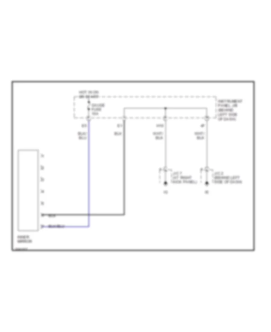
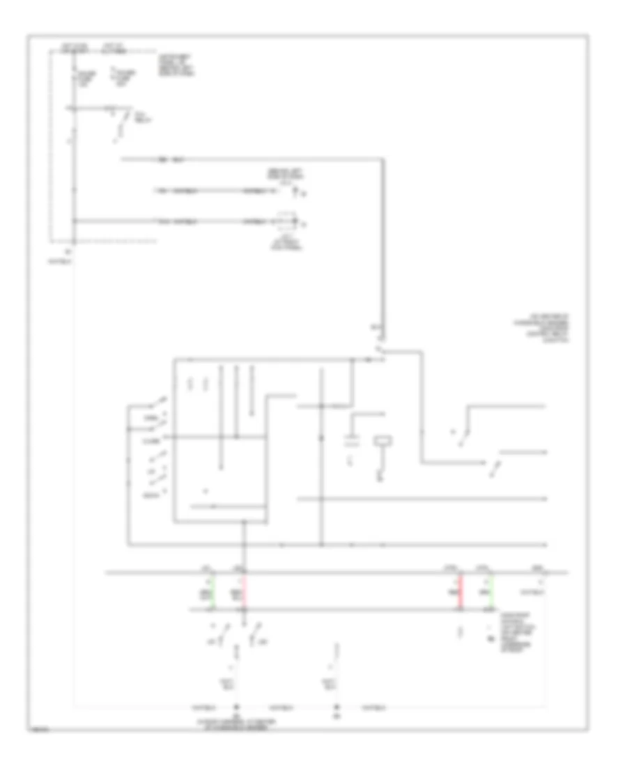
Electrochromic Mirror Wiring Diagram for Toyota Matrix 2006
List of elements for Electrochromic Mirror Wiring Diagram for Toyota Matrix 2006:
- Gauge fuse 10a
- H10
- Hot in on or start
- Inner mirror
- Instrument panel j/b (behind left side of dash)
- J/c 2 (behind left side of dash)
- J/c 7 (at right kick panel)
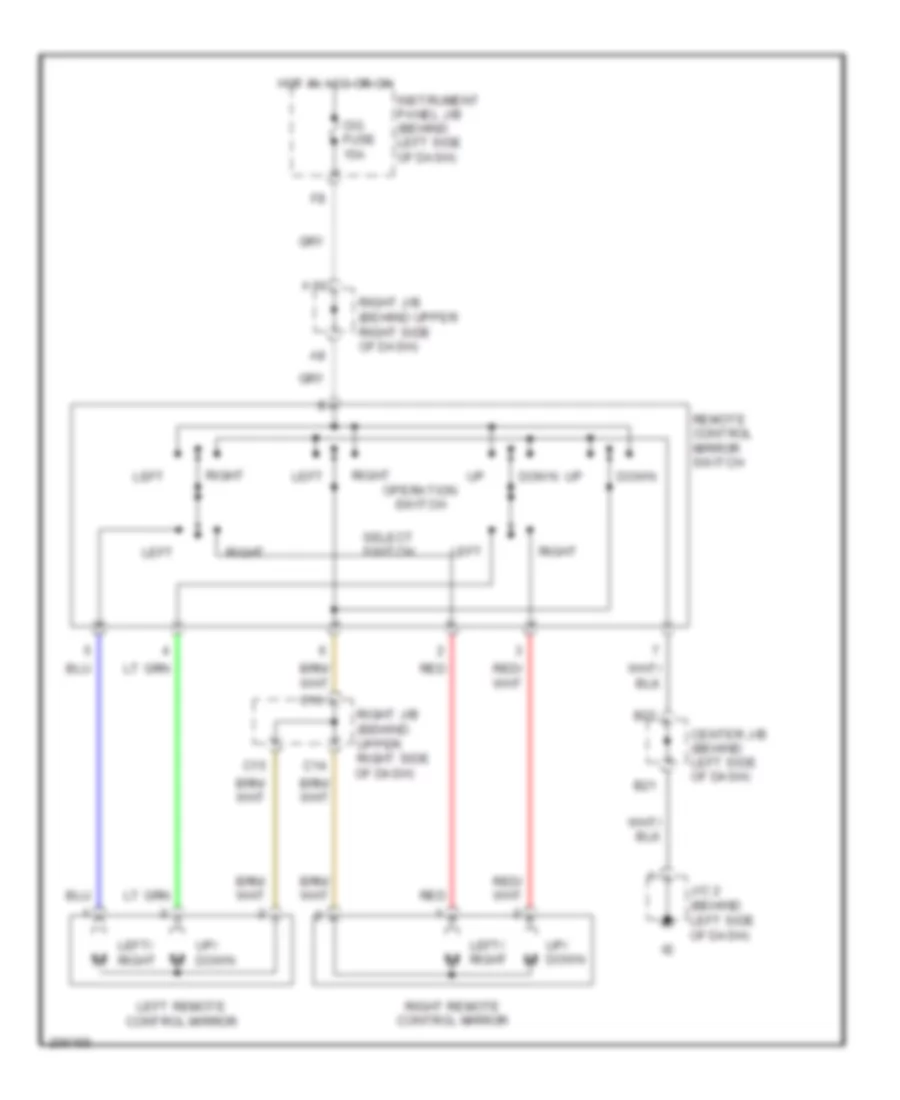
Power Mirrors Wiring Diagram for Toyota Matrix 2006
List of elements for Power Mirrors Wiring Diagram for Toyota Matrix 2006:
- A10
- B21
- B22
- C14
- C15
- C16
- Center j/b (behind left side of dash)
- Cig fuse 15a
- Down
- Hot in acc or on
- Instrument panel j/b (behind left side of dash)
- J/c 2 (behind left side of dash)
- Left
- Left remote control mirror
- Left/ right
- Operation switch
- Red
- Remote control mirror switch
- Right
- Right j/b (behind upper right side of dash)
- Right remote control mirror
- Select switch
- Up/ down
POWER TOP/SUNROOF
Power Top/Sunroof Wiring Diagram for Toyota Matrix 2006
List of elements for Power Top/Sunroof Wiring Diagram for Toyota Matrix 2006:
- (behind left side of dash) j/c 2
- (on center of windshield header) moon roof control relay & switch
- B5 (in roof harness, at center of windshield header)
- Close
- Down
- Gauge fuse 10a
- Gnd
- H10
- Hot at all times
- Hot in on or start
- Instrument panel j/b (behind left side of dash)
- J/c 7 (at right kick panel)
- Ls1
- Ls2
- Moon roof motor & limit switch (on center front underside of roof)
- Mtr+
- Mtr-
- Open
- P/w relay
- Power fuse 30a
- Red
POWER WINDOWS
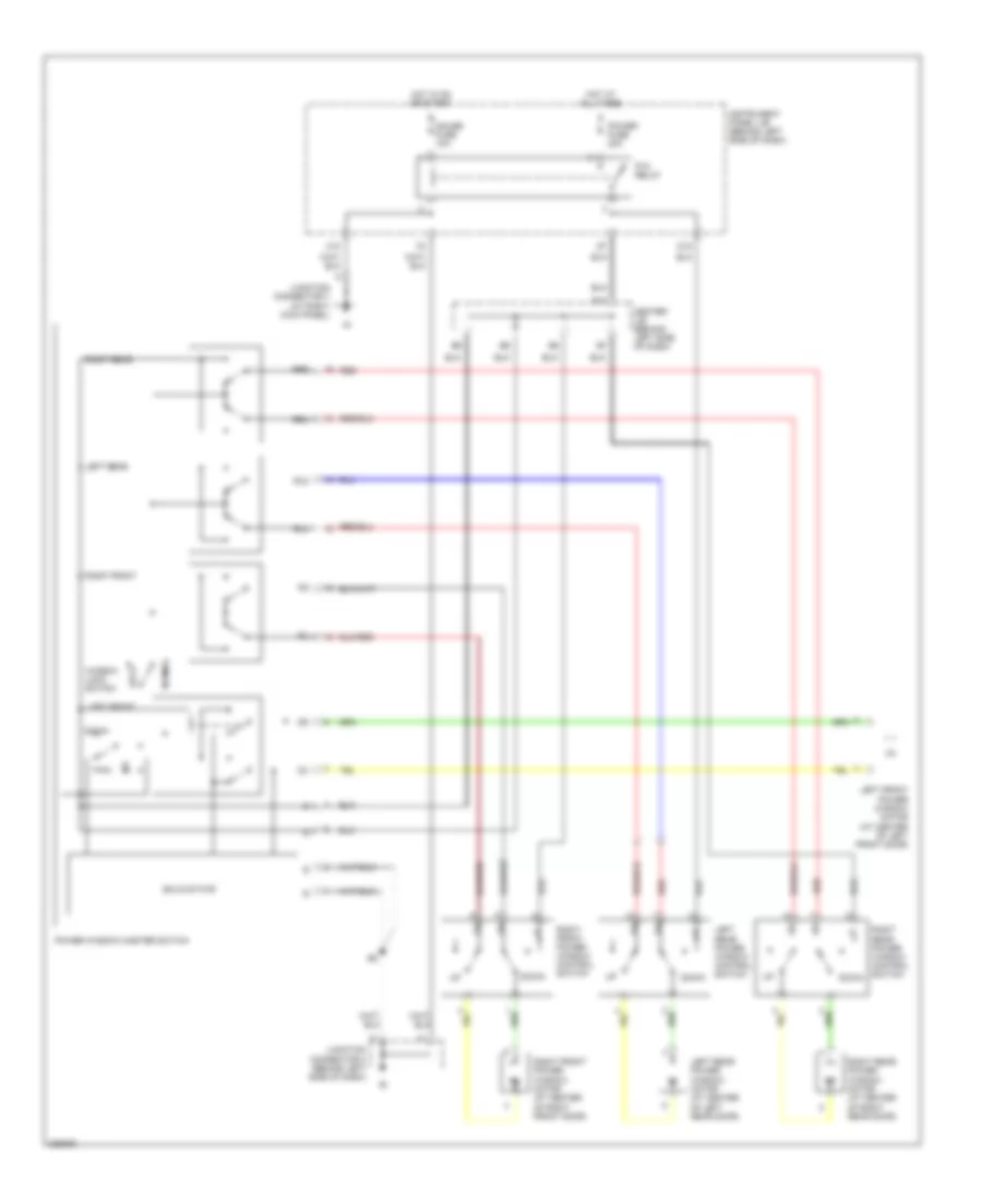
Power Windows Wiring Diagram for Toyota Matrix 2006
List of elements for Power Windows Wiring Diagram for Toyota Matrix 2006:
- B10
- Center j/b (behind left side of dash)
- D18
- Down
- Gauge fuse 10a
- H10
- Hot at all times
- Hot in on or start
- Instrument panel j/b (behind left side of dash)
- Junction connector 2 (behind left side of dash)
- Junction connector 7 (at right kick panel)
- Left front
- Left front power window motor (at center of left front door)
- Left rear
- Left rear power window control switch
- Left rear power window motor (at center of left rear door)
- Lock
- Normal
- P/w relay
- Power fuse 30a
- Power window master switch
- Red
- Right rear power window control switch
- Right front
- Right front power window control switch
- Right front power window motor (at center of right front door)
- Right rear
- Right rear power window motor (at center of right rear door)
- Rld
- Rlu
- Rrd
- Rru
- Solid state
- Window lock switch
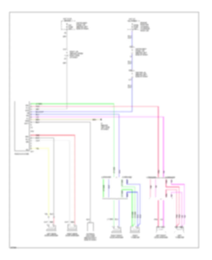
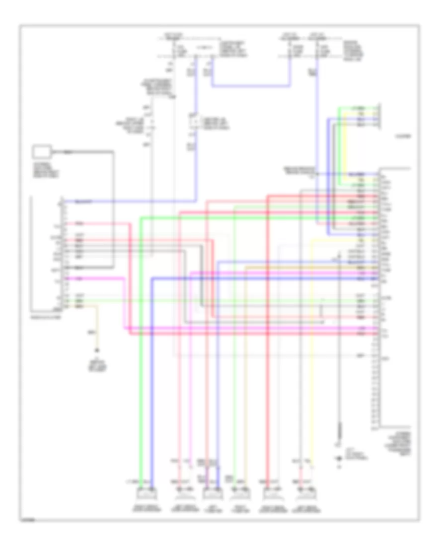
RADIO
Radio Wiring Diagram, without Navigation with Built-in Amplifier for Toyota Matrix 2006
List of elements for Radio Wiring Diagram, without Navigation with Built-in Amplifier for Toyota Matrix 2006:
- 4 speaker
- 6 speaker
- A10
- Acc
- Ant+
- Antenna amplifier (behind right side of dash)
- C17
- C20
- Center j/b (behind left side of dash)
- Cig fuse 15a
- Dome fuse 15a
- Engine room r/b (integral to engine room j/b)
- Fl+
- Fl-
- Fr+
- Fr-
- Gnd
- Hot at all times
- Hot in on or acc
- If (behind left side of dash)
- Instrument panel j/b (behind left side of dash)
- Left front door speaker
- Left rear door speaker
- Left tweeter
- Pnk
- R16
- R17
- Radio & player
- Red
- Right front door speaker
- Right j/b (behind upper right side of dash)
- Right rear door speaker
- Right tweeter
- Rl+
- Rl-
- Rr+
- Rr-
Radio Wiring Diagram, without Navigation with Separate Amplifier for Toyota Matrix 2006
List of elements for Radio Wiring Diagram, without Navigation with Separate Amplifier for Toyota Matrix 2006:
- (behind braking brake handle)
- (in instrument panel harness, behind right end of dash) i9
- A10
- Acc
- Amp fuse 30a
- Ant+
- Antenna amplifier (behind right side of dash)
- B2+
- C17
- C20
- Center j/b (behind left side of dash)
- Cig fuse 15a
- Dome fuse 15a
- Engine room r/b (integral to engine room j/b)
- Fl+
- Fl-
- Fr+
- Fr-
- Gnd
- Gnd2
- Hot at all times
- Hot in on or acc
- I14
- If (behind left side of dash)
- Instrument panel j/b (behind left side of dash)
- J/c 7 (at right kick panel)
- Left front door speaker
- Left rear door speaker
- Left tweeter
- Mute
- Nca
- Pnk
- Radio & player
- Red
- Right front door speaker
- Right j/b (behind upper right side of dash)
- Right rear door speaker
- Right tweeter
- Rl+
- Rl-
- Rr+
- Rr-
- S13
- S14
- Sld
- Stereo component amplifier (under front passenger seat)
- Twl+
- Twl-
- Twr+
- Twr-
- Tx+
- Tx-
- Wf1+
- Wf1-
- Wf2+
- Wf2-
- Woofer
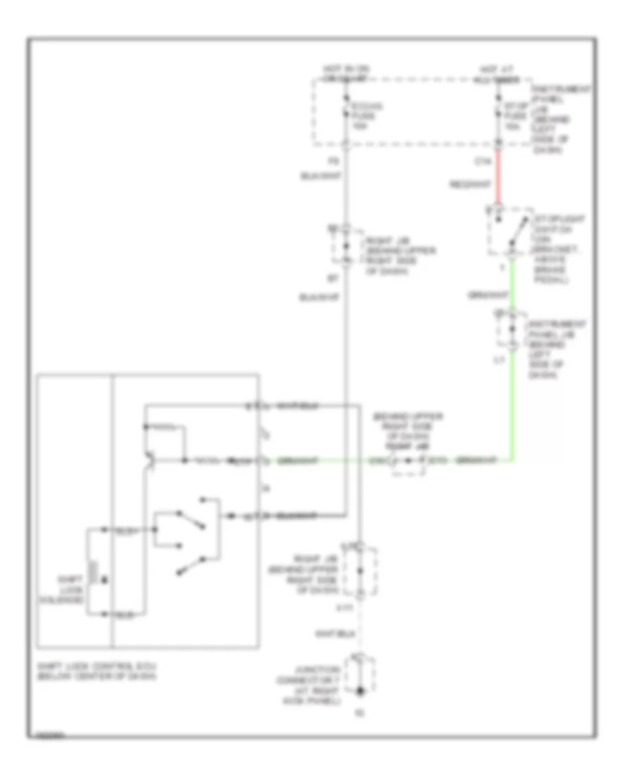
SHIFT INTERLOCK
Shift Interlock Wiring Diagram for Toyota Matrix 2006
List of elements for Shift Interlock Wiring Diagram for Toyota Matrix 2006:
- (behind upper right side of dash) right j/b
- A11
- A16
- C10
- C13
- C14
- Ecu-ig fuse 10a
- Hot at all times
- Hot in on or start
- Instrument panel j/b (behind left side of dash)
- Junction connector 7 (at right kick panel)
- Right j/b (behind upper right side of dash)
- Shift lock control ecu (below center of dash)
- Shift lock solenoid
- Sls+
- Sls-
- Stop fuse 15a
- Stoplight switch (on bracket, above brake pedal)
- Stp
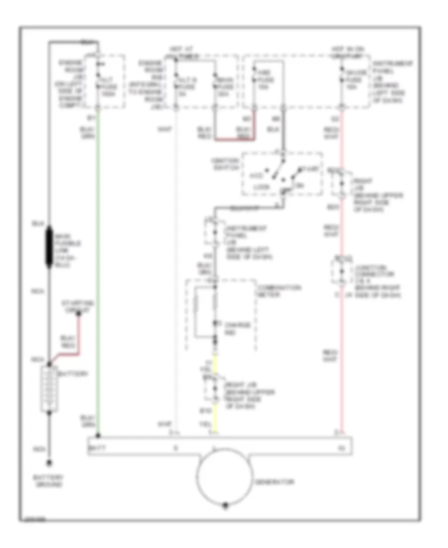
STARTING/CHARGING
Charging Wiring Diagram for Toyota Matrix 2006
List of elements for Charging Wiring Diagram for Toyota Matrix 2006:
- Acc
- Alt fuse 100a
- Alt-s fuse 5a
- Am2 fuse 15a
- B10
- B20
- B22
- Batt
- Battery
- Battery ground
- Charge ind
- Combination meter
- Engine room j/b (on left side of engine compt)
- Engine room r/b (integral to engine room j/b)
- Gauge fuse 10a
- Generator
- Hot at all times
- Hot in on or start
- Ignition switch
- Instrument panel j/b (behind left side of dash)
- Junction connector 3 & 4 (behind right side of dash)
- Lock
- Main fuse 30a
- Nca
- Off
- Right j/b (behind upper right side of dash)
- Start
- Starting circuit
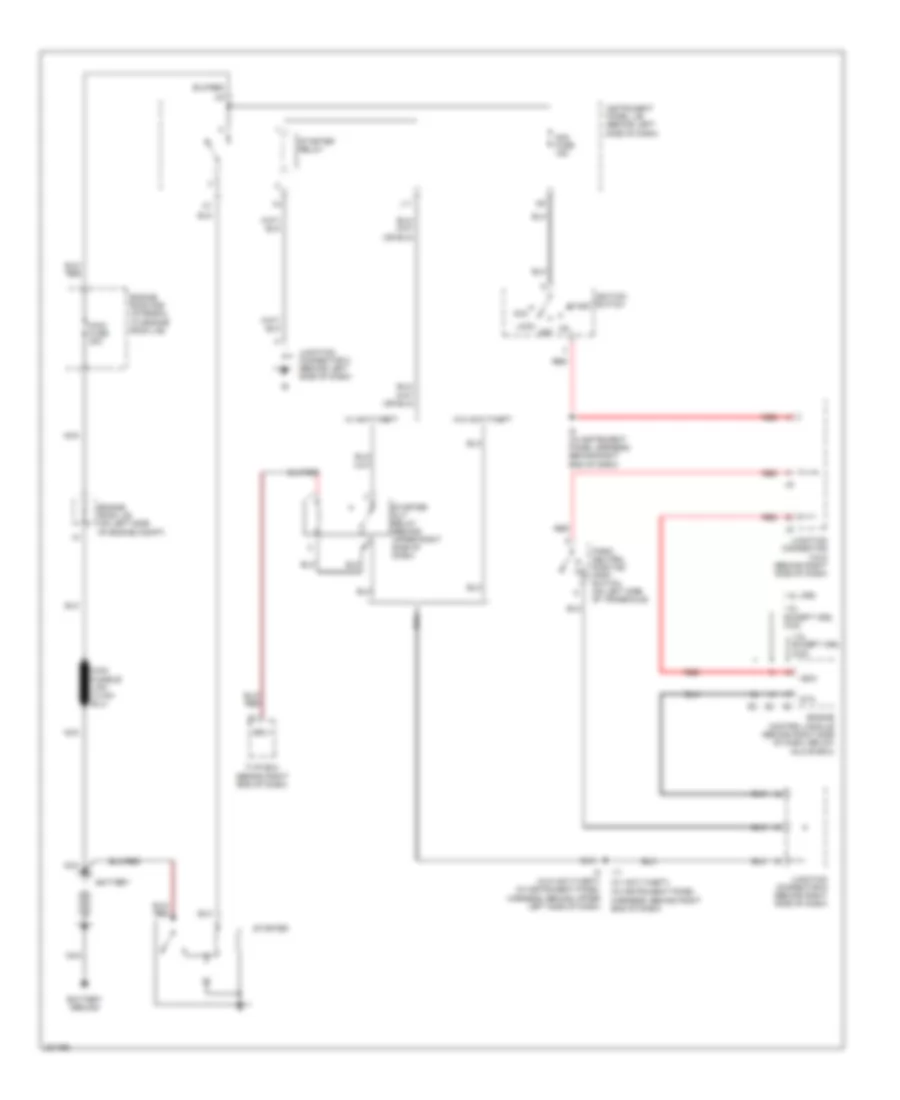
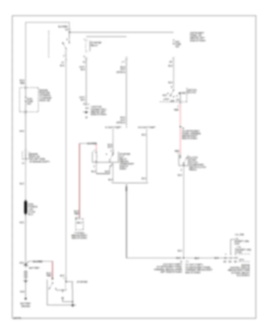
Starting Wiring Diagram, A/T for Toyota Matrix 2006
List of elements for Starting Wiring Diagram, A/T for Toyota Matrix 2006:
- (in instrument panel harness, behind right end of dash)
- (w/ anti-theft)
- (w/o anti-theft) (in instrument panel harness, behind upper left side of dash)
- 1.8l except xrs, 2wd
- 1.8l except xrs, 4wd
- 1.8l xrs
- Acc
- Am2 fuse 15a
- Battery
- Battery ground
- Engine control module (behind right side of dash, below glove box)
- Engine room j/b (on left side of engine compt)
- Engine room r/b (integral to engine room j/b)
- I11
- I9 (in instrument panel harness, behind right end of dash)
- Ignition switch
- Instrument panel j/b (behind left side of dash)
- Junction connector 2 (behind left side of dash)
- Junction connector 5 & 6 (behind right side of dash)
- Junction connector 6 (behind right side of dash)
- L11
- Lock
- Main fuse 30a
- Nca
- Nsw
- Off
- P/ n
- Park/ neutral position (pnp) switch (on left side of transaxle)
- Red
- Srly
- Sta
- Start
- Starter
- Starter cut relay (behind upper right side of dash)
- Starter relay
- Tvip ecu (behind right end of dash)
- W/ anti-theft
- W/o anti-theft
Starting Wiring Diagram, M/T for Toyota Matrix 2006
List of elements for Starting Wiring Diagram, M/T for Toyota Matrix 2006:
- (in instrument panel harness, behind right end of dash)
- (w/ anti-theft)
- (w/o anti-theft) (in instrument panel harness, behind upper left side of dash)
- 1.8l except xrs, 2wd
- 1.8l except xrs, 4wd
- 1.8l xrs
- Acc
- Am2 fuse 15a
- Battery
- Battery ground
- Clutch start switch (on bracket, above clutch pedal)
- Engine control module (behind right side of dash, below glove box)
- Engine room j/b (on left side of engine compt)
- Engine room r/b (integral to engine room j/b)
- I11
- I9 (in instrument panel harness, behind right end of dash)
- Ignition switch
- Instrument panel j/b (behind left side of dash)
- Junction connector 2 (behind left side of dash)
- L11
- Lock
- Main fuse 30a
- Nca
- Off
- Red
- Srly
- Sta
- Start
- Starter
- Starter cut relay (behind upper right side of dash)
- Starter relay
- Tvip ecu (behind right end of dash)
- W/ anti-theft
- W/o anti-theft
SUPPLEMENTAL RESTRAINTS
Supplemental Restraints Wiring Diagram (1 of 2) for Toyota Matrix 2006
List of elements for Supplemental Restraints Wiring Diagram (1 of 2) for Toyota Matrix 2006:
- (at left "b" pillar) (if equipped) left front side air bag sensor
- (top of left rear door) (if equipped) left curtain shield air bag squib
- (under left side of rear seat) (if equipped) left rear side air bag sensor
- +sl
- +sr
- -sl
- -sr
- A12
- A13
- A14
- Air bag sensor assembly (below center of dash)
- B11
- B22
- Bbd+
- Bbd-
- Bbl+
- Bbl-
- Bbp+
- Bbp-
- Bbr+
- Bbr-
- Bcl+
- Bcl-
- Bcr+
- Bcr-
- C17
- D2+
- D2-
- Dbe+
- Dbe-
- Dsp+
- Dsp-
- Ecu b fuse 10a
- Fsp+
- Fsp-
- Gauge fuse 10a
- Gsw2
- Hot at all times
- Hot in on or start
- Icd+
- Icd-
- Icp+
- Icp-
- Ig+
- Ig2
- Instrument panel j/b (behind left side of dash)
- Left front air bag sensor (behind left side of grille)
- Left pretensioner (at bottom of left "b" pillar)
- Left side air bag squib (if equipped) (near base of left "b" pillar)
- Option connector (passenger air bag on-off indicator light)
- P-ab
- P2+
- P2-
- Paon
- Pbew
- Pd+
- Pd-
- Pnk
- Pp+
- Pp-
- Red
- Right curtain shield air bag squib (if equipped) (top of right rear door)
- Right front air bag sensor (behind right side of grille)
- Right j/b (behind upper right side of dash)
- Right pretensioner (at bottom of right "b" pillar)
- Right rear side air bag sensor (if equipped) (under right side of rear seat)
- Right side air bag sensor (if equipped) (at right "b" pillar)
- Right side air bag squib (if equipped) (near base of right "b" pillar)
- Sfd+
- Sfd-
- Sfp+
- Sfp-
- Sil
Supplemental Restraints Wiring Diagram (2 of 2) for Toyota Matrix 2006
List of elements for Supplemental Restraints Wiring Diagram (2 of 2) for Toyota Matrix 2006:
- (behind left side of dash) j/c 2
- (except xrs: at rear left side of cylinder head) (xrs: at rear of engine) ec
- (in dash harness, behind instrument panel j/b)
- (in instrument panel harness, at left side of dash)
- Acc
- Air bag squib (front passenger air bag assembly) (behind right side of dash)
- Air bag squib (steering wheel pad) (under steering wheel pad)
- Am2
- Bgnd
- Bsw
- C11
- Center j/b (behind left side of dash)
- Combination meter
- D2+
- D2-
- Data link connector 3 (below left side of dash)
- Dia
- Engine control module (behind right side of dash, below glove box)
- F/ps
- Fsr+
- Fsr-
- Gnd
- Hot at all times
- I10
- Ig2
- Ignition switch
- Instrument panel j/b (behind left side of dash)
- J/c 5 (behind right side of dash)
- Left buckle switch & seat position sensor (in left front seat belt buckle)
- Left front occupant classification sensor (under front passenger seat)
- Left rear occupant classification sensor (under front passenger seat)
- Lock
- Occupant classification ecu (under front passenger seat)
- Off on
- Red
- Right buckle switch (in right front seat belt buckle)
- Right front occupant classification sensor (under front passenger seat)
- Right rear occupant classification sensor (under front passenger seat)
- Seat position air bag sensor
- Sgd1
- Sgd2
- Sgd3
- Sgd4
- Sig1
- Sig2
- Sig3
- Sig4
- Sil
- Srs ind
- Start
- Svc1
- Svc2
- Svc3
- Svc4
TRANSMISSION
A/T Wiring Diagram, 2WD (1 of 2) for Toyota Matrix 2006
List of elements for A/T Wiring Diagram, 2WD (1 of 2) for Toyota Matrix 2006:
- (2006)
- (below left end of dash) data link connector 3
- (left front suspension tower) eb
- (right front side of engine compt)
- Acc
- Batt
- Braid
- Center j/b (behind center of dash)
- Cruise control system
- E03
- E04
- Ec (rear left side of cyl head)
- Ed (left rear side of eng)
- Efi fuse 20a
- Efi relay
- Efi2 fuse 15a
- Electronically controlled transmission solenoid (on transaxle)
- Eng+
- Eng-
- Engine control module (behind right side of dash)
- Engine controls system
- Engine room r/b (left side of engine compt)
- Ge01
- Hot at all times
- Ignition switch
- Instrument panel j/b (left side of dash)
- J/c 7 (right kick panel)
- Lock
- Me01
- Mrel
- Neo
- Od1
- Pnk
- Run
- Skid control ecu w/ actuator
- Slt+
- Slt-
- Start
- Vsc+
- Vsc-
A/T Wiring Diagram, 2WD (2 of 2) for Toyota Matrix 2006
List of elements for A/T Wiring Diagram, 2WD (2 of 2) for Toyota Matrix 2006:
- (2005)
- +bm
- A/t shift lever position switch (left side of transaxle)
- B20
- B22
- C11
- C13
- C14
- C18
- C20
- C8 center j/b (left side of dash)
- Combination meter
- Cruise control system
- E01
- E02
- Ec (rear left side of cyl head)
- Ed (left rear side of eng)
- Engine control module (behind right side of dash)
- Engine coolant temperature sensor (on rear of engine, on coolant outlet)
- Engine room r/b (left side of engine compt)
- Etcs fuse 10a
- Gauge fuse 10a
- Hot at all times
- Hot in on or start
- Instrument panel j/b (behind left side of dash)
- J/c 3 (behind right side of dash)
- J/c 3, j/c 4 (right side of dash)
- J/c 5, j/c 6 (right side of dash)
- J/c 7 (right kick panel)
- K10
- O/d main switch
- O/d off indicator
- Od1
- Odlp
- Odms
- Right j/b (behind upper right side of dash)
- Spd
- Stop fuse 15a
- Stop light switch (on bracket, above brake pedal)
- Stp
- Throttle control motor/throttle position sensor (on throttle body assembly)
- Thw
- Vta1
- Vta2
A/T Wiring Diagram, 4WD (1 of 2) for Toyota Matrix 2006
List of elements for A/T Wiring Diagram, 4WD (1 of 2) for Toyota Matrix 2006:
- (2006)
- (below left end of dash) data link connector 3
- (left front suspension tower) eb
- (right front side of engine compt)
- Acc
- Batt
- Center j/b (behind center of dash)
- Cruise control system
- E03
- Ec (rear left side of cyl head)
- Ed (left rear side of eng)
- Efi fuse 15a
- Efi relay
- Electronically controlled transmission solenoid (on transaxle)
- Eng+
- Eng-
- Engine control module (behind right side of dash)
- Engine controls system
- Engine room r/b (left side of engine compt)
- Hot at all times
- Ignition switch
- Instrument panel j/b (left side of dash)
- J/c 3 (right side of dash)
- J/c 7 (right kick panel)
- Lock
- Neo
- Od1
- Pnk
- Run
- Skid control ecu w/ actuator
- Slt+
- Slt-
- Start
- Th0
- Vsc+
- Vsc-
A/T Wiring Diagram, 4WD (2 of 2) for Toyota Matrix 2006
List of elements for A/T Wiring Diagram, 4WD (2 of 2) for Toyota Matrix 2006:
- (2005)
- +bm
- A/t shift lever position switch (left side of transaxle)
- B20
- B22
- C11
- C13
- C14
- C18
- C20
- C8 center j/b (left side of dash)
- Combination meter
- Cruise control system
- E01
- E02
- Ed (left rear side of eng)
- Engine control module (behind right side of dash)
- Engine coolant temperature sensor (on rear of engine, on coolant outlet)
- Engine room r/b (left side of engine compt)
- Etcs fuse 10a
- Gauge fuse 10a
- Hot at all times
- Hot in on or start
- Instrument panel j/b (behind left side of dash)
- J/c 3 (behind right side of dash)
- J/c 3, j/c 4 (right side of dash)
- J/c 5, j/c 6 (right side of dash)
- J/c 7 (right kick panel)
- K10
- Mrle
- O/d main switch
- O/d off indicator
- Od1
- Odlp
- Odms
- Right j/b (behind upper right side of dash)
- Spd
- Stop fuse 15a
- Stop light switch (on bracket, above brake pedal)
- Stp
- Throttle position sensor (throttle body assembly)
- Thw
- Vta
- Vta1
WARNING SYSTEMS
Warning Systems Wiring Diagram for Toyota Matrix 2006
List of elements for Warning Systems Wiring Diagram for Toyota Matrix 2006:
- (2005 models) i10
- (behind left side of dash) center j/b
- (behind left side of dash) instrument panel j/b
- (behind left side of dash) junction connector 2
- (under front passenger seat)
- (usa)
- 2005 models
- 2005 w/o navigation
- A11
- A13
- A14
- A15
- Airbag sensor assembly (below center of dash)
- B11
- B16
- B18
- B21
- Bgnd
- Bsw
- Buzzer
- C12
- C17
- C19
- C20
- Canada
- Center j/b (behind left side of dash)
- Combination meter
- Combination switch
- Daytime running light relay (usa) (behind left side of dash)
- Dome fuse 15a
- Door ind
- Ec (xrs: at rear of engine) (except xrs: at rear left side of cylinder head)
- Ecu-b fuse 10a
- Engine room r/b (integral to engine room j/b)
- Front passenger seat belt warning light
- Fsp+
- Fsp-
- Fsr+
- Fsr-
- Gauge fuse 10a
- Gnd
- Head
- Hot at all times
- Hot in on or start
- I7 (in instrument panel harness, behind right side of dash)
- Ig+
- Instrument panel j/b (behind left side of dash)
- Integration relay (on instrument panel j/b)
- Junction connector 5 (behind right side of dash)
- Junction connector 7 (at right kick panel)
- Lapl
- Left buckle switch (in left front seat belt buckle)
- Left front door courtesy switch
- Light control switch
- Occupant classification ecu
- Off
- Pbew
- Prcty
- Red
- Right buckle switch (in right front seat belt buckle)
- Right j/b (behind upper right side of dash)
- Right r/b (integral to right j/b)
- Seat belt indicator
- System & 2006 models
- Tail
- Tail fuse 15a
- Tail relay
- Unlock warning switch (on steering column, behind ignition key cylinder)
- Usa
- W/ door locks
- W/ navigation system
- W/o door locks
WIPER/WASHER
Front Wiper/Washer Wiring Diagram for Toyota Matrix 2006
List of elements for Front Wiper/Washer Wiring Diagram for Toyota Matrix 2006:
- B16
- B22
- C11
- C14
- Combination meter
- Combination switch
- Eb (at front side of right fender)
- Front washer motor (at right front corner of engine compt, on washer fluid reservoir)
- Front washer switch
- Front wiper motor (on left side of firewall)
- Front wiper switch
- Gauge fuse 10a
- High
- Hot in on or start
- Instrument panel j/b (behind left side of dash)
- Int
- Junction connector (behind left side of dash)
- Junction connector 1 (at left side of engine compt)
- Low/ mist
- Off
- Right j/b (behind upper right side of dash)
- Solid state
- W/ intermittent volume switch
- W/o intermittent volume switch
- Washer fuse 15a
- Washer level ind
- Washer level sensor (at right front corner of engine compt, on washer reservoir)
- Wiper fuse 25a
Rear Wiper/Washer Wiring Diagram for Toyota Matrix 2006
List of elements for Rear Wiper/Washer Wiring Diagram for Toyota Matrix 2006:
- B21
- B22
- Bh (at left quarterpanel)
- C10
- C11
- C12
- C13
- C14
- C15
- Center j/b (behind left side of dash)
- Combination switch
- D11
- Diode (ig relay)
- Diode (rear wiper)
- Gauge fuse 10a
- Glass hatch courtesy switch
- Hot in on or start
- Ig relay
- Instrument panel j/b (behind left side of dash)
- Int
- Junction connector
- Junction connector 1 (at left side of engine compt)
- Junction connector 10 (at left rear of vehicle)
- Junction connector 2 (behind left side of dash)
- Junction switch
- Off
- Pnk
- Rear washer motor
- Rear wiper & washer switch
- Rear wiper motor
- Rear wiper relay (in center of back door)
- Right j/b (behind upper right side of dash)
- Rr wiper fuse 15a
- Washer 1
- Washer 2
- Washer fuse 15a

 Dansk
Dansk Deutsch
 Ελληνικά
 English
 English
 Español
 Suomi
Suomi Français
 Français
 עברית
עברית Hrvatski
 Magyar
 Italiano
 日本語
日本語 한국어
한국어 Nederlands
 Polski
 Português
 Português
 Română
 Русский
 Slovenčina
 Slovenščina
 Svenska
 Türkçe
 中文 (中国)