TRANSMISSION
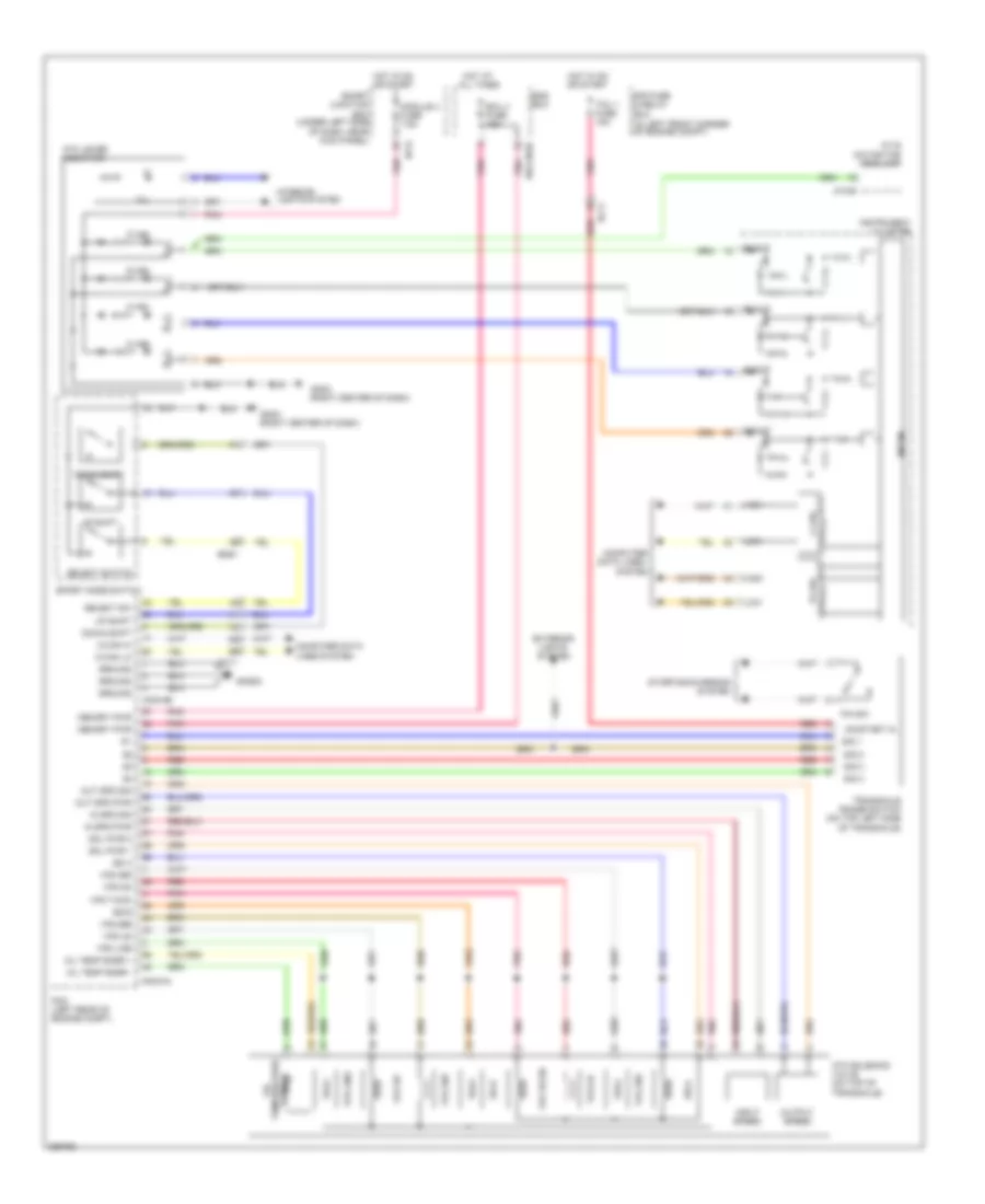
Transmission Wiring Diagram for Hyundai Elantra GLS 2012
List of elements for Transmission Wiring Diagram for Hyundai Elantra GLS 2012:
- (in left front corner of engine compt)
- (right center of dash)
- A/v & navigation head unit
- Atm lever indicator
- Atm solenoid valve (on top of transaxle)
- B-can transceiver
- C-can hi
- C-can lo
- C-can transceiver
- Cng-aa
- Cng-ab
- Computer
- Computer data lines system
- D ind
- Data lines
- Down shift
- D_out
- E/r fuse & relay box
- Ec11
- Ecu 4 fuse 15a
- Em61
- Ems box
- Exterior lights system
- Gm02
- Gng02
- Ground
- High
- Hot at all times
- Hot in on or start
- I/p-h
- Ill.
- In spd pwr
- In spd sig
- Input speed
- Instrument cluster
- Interior lights system
- Low
- M15-b
- Memory pwr
- Micom
- Module 4 fuse 7.5a
- N ind
- N_out
- Oil temp snsr +
- Oil temp snsr -
- On/start in
- Out spd pwr
- Out spd sig
- Output speed
- P ind
- P/n sw
- Pcm (left rear of engine compt)
- Pnk
- P_out
- R ind
- Red
- R_out
- Select sw
- Select switch
- Sensor temperature oil
- Sig 1
- Sig 2
- Sig 3
- Sig 4
- Smart junction box (under left side of dash, near kick panel)
- Sol pwr 1
- Sol pwr 2
- Sport mode switch
- Ss a
- Ss b
- Ss-a
- Starting/charging system
- System
- Tcu 1 fuse 15a
- Transaxle range switch (on top left side of transaxle)
- U/r-cngb
- Up shift
- Vfs 26b
- Vfs 35r
- Vfs line
- Vfs od
- Vfs t/con
- Vfs ud
 Čeština
 Deutsch
 Ελληνικά
 English
 English
 Español
 Suomi
Suomi Français
 Français
 עברית
עברית Hrvatski
 Magyar
 Italiano
 日本語
日本語 한국어
한국어 Nederlands
 Polski
 Português
 Português
 Română
 Русский
 Slovenčina
 Slovenščina
 Svenska
 Türkçe
 中文 (中国)
 Dansk
Dansk