AIR CONDITIONING
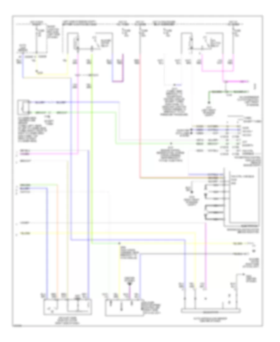
Automatic A/C Wiring Diagram (1 of 2) for Ford Flex SEL 2011
 https://portal-diagnostov.com/license.html
Automotive Electricians Portal FZCO
Automotive Electricians Portal FZCO
https://portal-diagnostov.com/license.html
https://portal-diagnostov.com/license.html
Automotive Electricians Portal FZCO
Automotive Electricians Portal FZCO
List of elements for Automatic A/C Wiring Diagram (1 of 2) for Ford Flex SEL 2011:
- Ambient air temp sens
- Ambient air temperature sensor (behind center of front bumper)
- Aux blwr pwr
- Aux blwr rly request
- Aux mode door ccw
- Aux mode door cw
- Aux mode door fdbk
- Aux temp door ccw
- Aux temp door cw
- Aux temp door fdbk
- Auxiliary blower circuit
- Auxiliary climate control assembly (w/ auxiliary
- Auxiliary mode door actuator (w/ auxiliary climate control) (left rear quarterpanel)
- Auxiliary temperature blend door actuator (w/ auxiliary climate control) (left rear quarterpanel)
- C210
- C213
- C2239
- C2280a
- C228a
- C228b
- C3007
- C312
- Ch112
- Ch122
- Ch123
- Ch207
- Ch208
- Ch212
- Ch213
- Ch228
- Ch229
- Ch238
- Ch239
- Ch242
- Ch243
- Ch244
- Ch245
- Cha34
- Cha35
- Cha36
- Cha37
- Chs04
- Chs09
- Chs13
- Chs14
- Chs29
- Chs30
- Climate control)
- Computer data lines system
- Defogger system
- Defrost request
- Defrost/panel/floor mode door actuator
- Driver sunload
- Driver temp door ccw
- Driver temperature blend door actuator (left side of hvac unit)
- Drv hs high status
- Drv hs low status
- Drv hs request
- Drv temp door cw
- Drv temp door fdbk
- Evap temp sens
- Evaporator discharge air temperature sensor (left side of hvac unit)
- Front blower pwm
- Front blower relay
- Fuse 10a
- G203 (center of dash)
- Gd116
- Gnd
- Hot at all times
- Hvac module (center of dash)
- In car temp sensor
- In-vehicle temperature sensor (left center of dash)
- Lh111
- Mode door ccw
- Mode door cw
- Mode door fdbk
- Ms can+
- Ms can-
- Pass hs high status
- Pass hs low status
- Pass hs request
- Pass temp act fdbk
- Pass temp door ccw
- Pass temp door cw
- Passenger sunload
- Passenger temperature blend door actuator (right side of dash)
- Rear blower pot
- Rear in-vehicle temperature sensor (w/ auxiliary climate control) (behind left quarterpanel)
- Rear led sig 1
- Rear led sig 2
- Rear led sig 3
- Rear mode
- Rear temp pot
- Recirc door ccw
- Recirc door cw
- Return
- Rh111
- S201 (main wiring harness, near breakout to instrument cluster)
- S202 (main wiring harness, near breakout to hvac module)
- Sbp15
- Seats system
- Smart junction box (sjb) (left side of dash)
- Vbatt
- Vdb06
- Vdb07
- Vh101
- Vh406
- Vh407
- Vh414
- Vh416
- Vh417
- Vh436
- Vh440
- Vh441
- Vha09
- Vha15
- Vha17
- Vha18
- Vha25
- Vref
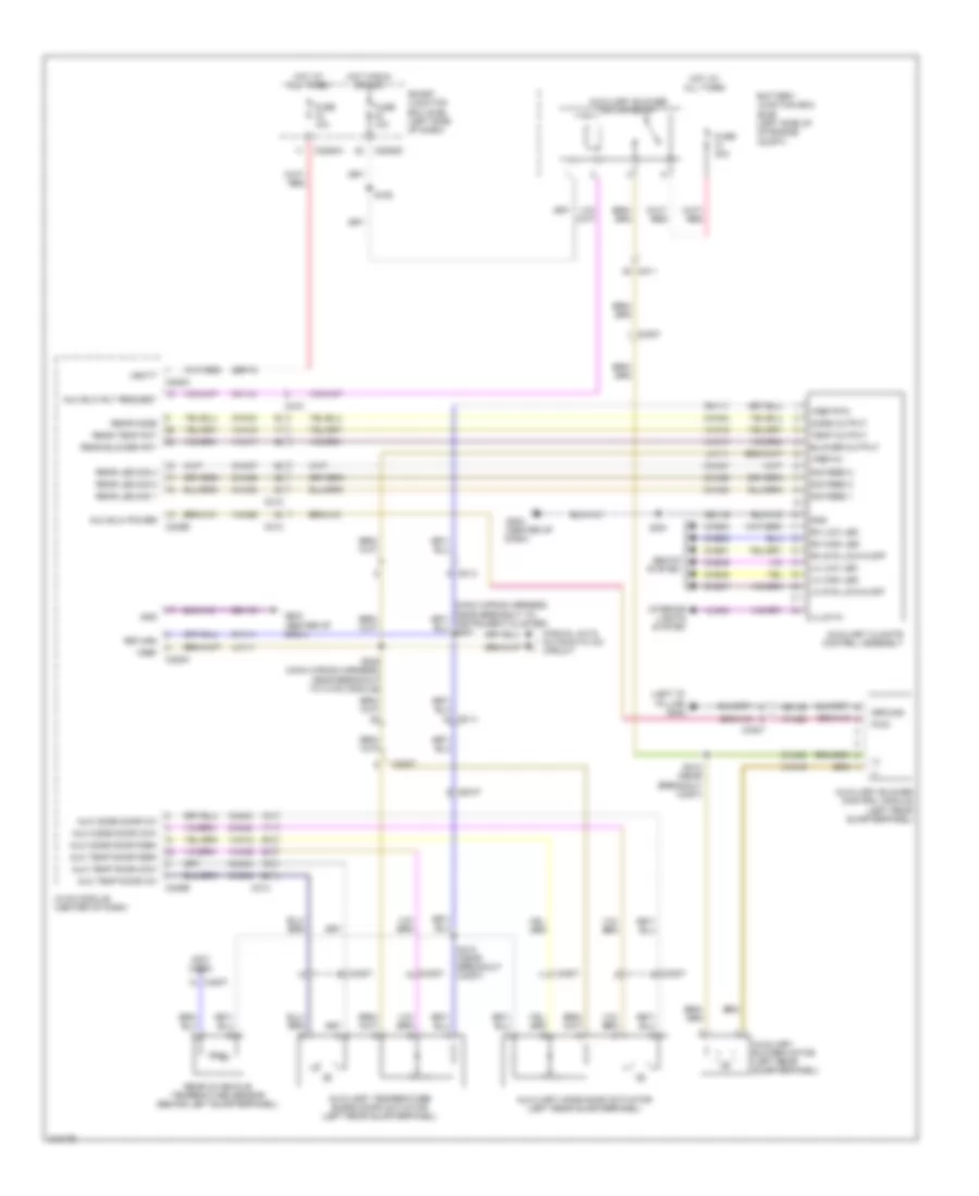
Automatic A/C Wiring Diagram (2 of 2) for Ford Flex SEL 2011
List of elements for Automatic A/C Wiring Diagram (2 of 2) for Ford Flex SEL 2011:
- (center of dash) g203
- (left side of engine compt) battery junction box (bjb)
- (not used)
- A/c clutch relay
- A/c compressor clutch field coil (left front of engine)
- Accr
- Air inlet mode door actuator (right side of dash)
- Auto- lamp sensor in
- Autolamp/sunload sensor (center of dash)
- Blower motor (right side of hvac unit)
- Blower motor relay
- Blower motor speed controller (right side of hvac unit)
- C1381b
- C1381e
- C145
- C175b
- C175e
- C192
- C210
- C2280b
- C2280e
- Ch302
- Cht
- Computer data lines system
- Cylinder head temperature sensor (turbo (left): rear of left cylinder head) (turbo (right): front of right cylinder head) (non-turbo: top front of right cylinder head)
- E-sigrtn
- Electronics
- Engine cooling fan motor (behind radiator)
- Except turbo
- Fan ctrl variable
- Fuse 10a
- Fuse 15a
- Fuse 40a
- Fuse 5a
- Fuse 80a
- G100 (right front of engine compt)
- G101 (left front of engine compt)
- G202 (center of dash)
- Gnd
- Hot at all times
- Hot in run or acc
- Hot w/ pcm power relay energized
- Hs can +
- Hs can -
- Motor +
- Motor -
- Nca
- Powertrain control module (pcm) (rear of engine compt)
- Pwm
- Pwr
- Re405
- S127 (engine control sensor & fuel charge wiring harness, near breakout to fuel injector 6)
- S141 (turbo: near breakout to powertrain control module) (except turbo: dash panel to headlamp junction wiring harness, in breakout to a/c pressure transduer)
- S167
- S262 (main wiring harness, near breakout to hvac module)
- Smart junction box (sjb) (left side of dash)
- Solid state
- Turbo
- Vdb04
- Vdb05
- Ve712
- Vec03
Auxiliary Blower Wiring Diagram for Ford Flex SEL 2011
List of elements for Auxiliary Blower Wiring Diagram for Ford Flex SEL 2011:
- (+)
- (-)
- (left "d" pillar) g302
- (not used)
- Aux blw power
- Aux blw rly request
- Aux mode door ccw
- Aux mode door cw
- Aux mode door fdbk
- Aux temp door ccw
- Aux temp door cw
- Aux temp door fdbk
- Auxiliary blower control module (left rear quarterpanel)
- Auxiliary blower motor (left rear quarterpanel)
- Auxiliary blower motor relay
- Auxiliary climate control assembly
- Auxiliary mode door actuator (left rear quarterpanel)
- Auxiliary temperature blend door actuator (left rear quarterpanel)
- Battery junction box (bjb) (left side of of engine compt)
- Blower output
- C210
- C211
- C213
- C2280a
- C2280d
- C228a
- C228b
- C3007
- C312
- Ch112
- Ch242
- Ch243
- Ch244
- Ch245
- Cha02
- Cha34
- Cha35
- Cha36
- Cha37
- Chs47
- Chs48
- Chs49
- Chs51
- Chs52
- Chs53
- Fuse 10a
- Fuse 30a
- G203 (center of dash)
- Gd116
- Gd149
- Gnd
- Ground
- Hot at all times
- Hot in run or acc
- Hvac module (center of dash)
- Illum in
- Interior lights system
- Lh high led
- Lh low led
- Lh sys low/hi/off
- Lh111
- Manual a/c & automatic a/c circuit
- Mode output
- Pwm
- Rear blower pot
- Rear in-vehicle temperature sensor (behind left quarterpanel)
- Rear led sig 1
- Rear led sig 2
- Rear led sig 3
- Rear mode
- Rear temp pot
- Return
- Rh high led
- Rh low led
- Rh sys low/hi/off
- Rh111
- S193
- S202 (main wiring harness, near breakout to hvac module)
- S381
- S410 (near breakout c3007)
- S412 (near breakout c3007)
- Sbp15
- Seats system
- Sig feed 1
- Sig feed 2
- Sig feed 3
- Smart junction box (sjb) (left side of dash)
- Temp output
- Vbatt
- Vha09
- Vha15
- Vha17
- Vha18
- Vha19
- Vha25
- Vln04
- Vref
- Vref 5v
- Vref rtn
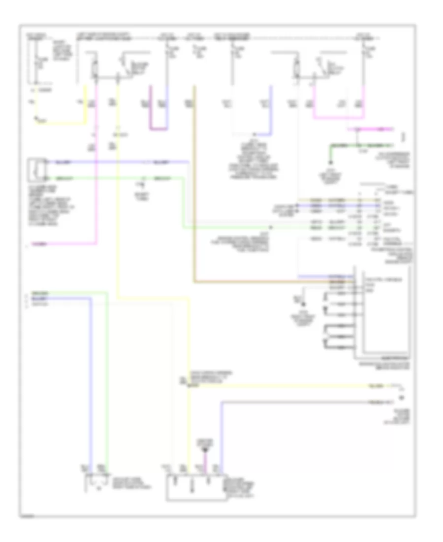
Manual A/C Wiring Diagram (1 of 2) for Ford Flex SEL 2011
List of elements for Manual A/C Wiring Diagram (1 of 2) for Ford Flex SEL 2011:
- Ambient air temp sens
- Ambient air temperature sensor (behind center of front bumper)
- Aux blwr pwr
- Aux blwr rly request
- Aux mode door ccw
- Aux mode door cw
- Aux mode door fdbk
- Aux temp door ccw
- Aux temp door cw
- Aux temp door fdbk
- Auxiliary blower circuit
- Auxiliary climate control assembly (w/ auxiliary
- Auxiliary mode door actuator (w/ auxiliary climate control) (left rear quarterpanel)
- Auxiliary temperature blend door actuator (w/ auxiliary climate control) (left rear quarterpanel)
- C210
- C213
- C2280a
- C228a
- C228b
- C3007
- C312
- Ch112
- Ch122
- Ch123
- Ch207
- Ch208
- Ch228
- Ch229
- Ch238
- Ch239
- Ch242
- Ch243
- Ch244
- Ch245
- Cha34
- Cha35
- Cha36
- Cha37
- Chs04
- Chs09
- Chs13
- Chs14
- Chs29
- Chs30
- Climate control)
- Computer data lines system
- Defogger system
- Defrost request
- Defrost/panel/floor mode door actuator
- Driver temp door ccw
- Driver temperature blend door actuator (left side of hvac unit)
- Drv hs high status
- Drv hs low status
- Drv hs request
- Drv temp door cw
- Drv temp door fdbk
- Evap temp sens
- Evaporator discharge air temperature sensor (left side of hvac unit)
- Front blower pwm
- Front blower relay
- Fuse 10a
- G203 (center of dash)
- Gd116
- Gnd
- Hot at all times
- Hvac module (center of dash)
- Lh111
- Mode door ccw
- Mode door cw
- Mode door fdbk
- Ms can+
- Ms can-
- Pass hs high status
- Pass hs low status
- Pass hs request
- Rear blower pot
- Rear in-vehicle temperature sensor (w/ auxiliary climate control) (behind left quarterpanel)
- Rear led sig 1
- Rear led sig 2
- Rear led sig 3
- Rear mode
- Rear temp pot
- Recirc door ccw
- Recirc door cw
- Return
- Rh111
- S201 (main wiring harness, near breakout to instrument cluster)
- S202 (main wiring harness, near breakout to hvac module)
- Sbp15
- Seats system
- Smart junction box (sjb) (left side of dash)
- Vbatt
- Vdb06
- Vdb07
- Vh101
- Vh406
- Vh407
- Vh436
- Vh440
- Vha09
- Vha15
- Vha17
- Vha18
- Vha25
- Vref
Manual A/C Wiring Diagram (2 of 2) for Ford Flex SEL 2011
List of elements for Manual A/C Wiring Diagram (2 of 2) for Ford Flex SEL 2011:
- (center of dash) g203
- (left side of engine compt) battery junction box (bjb)
- A/c clutch relay
- A/c compressor clutch field coil (left front of engine)
- Accr
- Air inlet mode door actuator (right side of dash)
- Blower motor (blower of hvac unit)
- Blower motor relay
- Blower motor speed controller (right side of hvac unit)
- C1381b
- C1381e
- C145
- C175b
- C175e
- C192
- C210
- C2280e
- Ch302
- Cht
- Computer data lines system
- Cylinder head temperature sensor (turbo (left): rear of left cylinder head) (turbo (right): front of right cylinder head) (non-turbo: top front of right cylinder head)
- E-sigrtn
- Electronics
- Engine cooling fan motor (behind radiator)
- Except turbo
- Fan ctrl variable
- Fuse 10a
- Fuse 15a
- Fuse 40a
- Fuse 5a
- Fuse 80a
- G100 (right front of engine compt)
- G101 (left front of engine compt)
- Gnd
- Hot at all times
- Hot in run or acc
- Hot w/ pcm power relay energized
- Hs can +
- Hs can -
- Motor +
- Motor -
- Nca
- Powertrain control module (pcm) (rear of engine compt)
- Pwm
- Pwr
- Re405
- S127 (engine control sensor & fuel charge wiring harness, near breakout to fuel injector 6)
- S141 (turbo: near breakout to powertrain control module) (except turbo: dash panel to headlamp junction wiring harness, in breakout to a/c pressure transducer)
- S167
- Smart junction box (sjb) (left side of dash)
- Turbo
- Vdb04
- Vdb05
- Ve712
- Vec03

 Čeština
 Deutsch
 Ελληνικά
 English
 English
 Español
 Suomi
Suomi Français
 Français
 עברית
עברית Hrvatski
 Magyar
 Italiano
 日本語
日本語 한국어
한국어 Nederlands
 Polski
 Português
 Português
 Română
 Русский
 Slovenčina
 Slovenščina
 Svenska
 Türkçe
 中文 (中国)