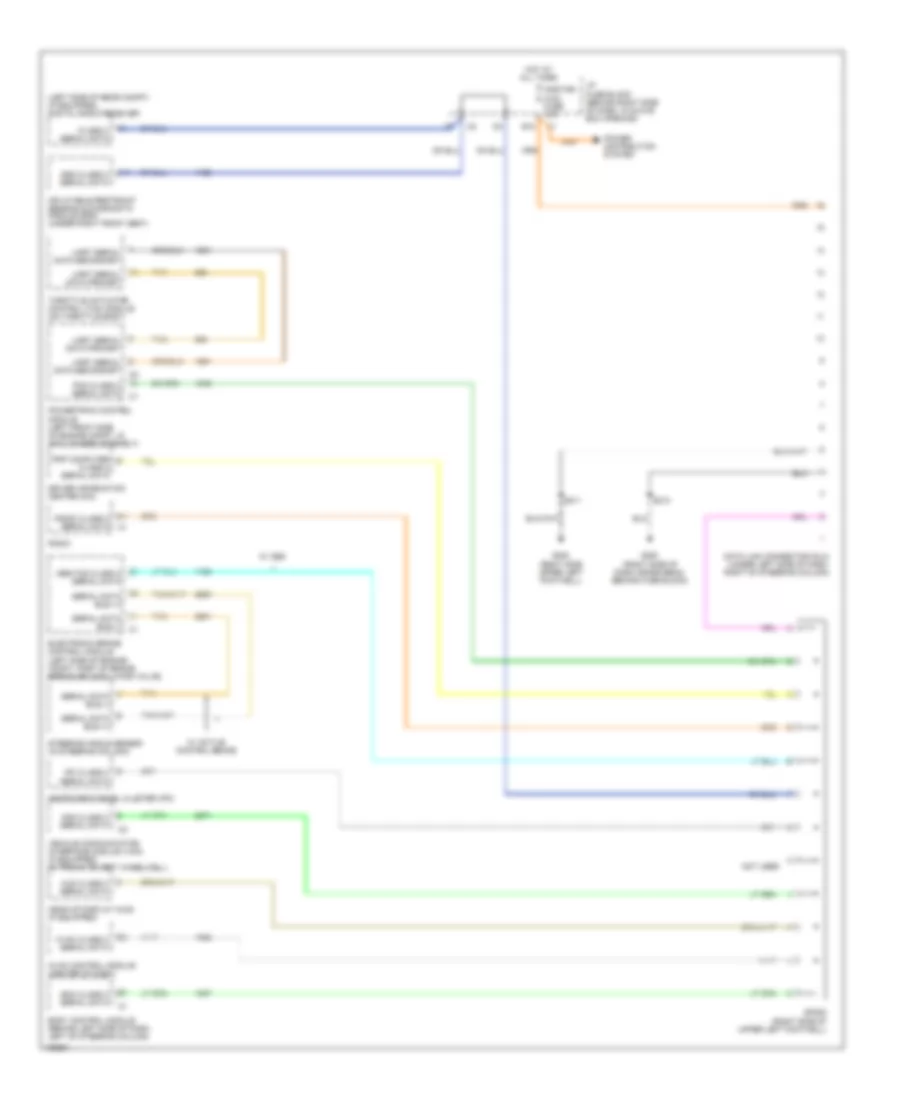
COMPUTER DATA LINES
Computer Data Lines Wiring Diagram for Pontiac Grand Prix GT 2004
List of elements for Computer Data Lines Wiring Diagram for Pontiac Grand Prix GT 2004:
- (left side of rear compt) (if equipped) digital radio receiver
- A11
- Abs/tcs class 2 serial data
- Adg class 2 serial data
- B10
- Bcm class 2 serial data
- Body control module (behind left side of dash, left of steering column)
- Class 2 serial data
- Data link connector (dlc) (under left side of dash, right of steering column)
- Driver information center (dic)
- Electronic brake control module (left side of engine compt, part of brake pressure modulator valve)
- G200 (right side of dash cross beam, behind fuse block)
- G202 (right side upper left footwell)
- Head-up display (hud) (if equipped)
- Hot at all times
- Hud class 2 serial data
- Hvac class 2 serial data
- Hvac control module (center of dash)
- I/p fuse block (behind right side of dash, in glove box opening)
- Inflatable restraint sensing & diagnostic module (sdm) (under right front seat)
- Instrument panel cluster (ipc)
- Ipc class 2 serial data
- Not used
- Onstar/ aldl fuse 10a
- Pcm class 2 serial data
- Power distribution system
- Powertrain control module (left front side of engine compt, in air cleaner assembly)
- Radio
- Radio class 2 serial data
- S211
- S213
- Sdm class 2 serial data
- Serial data bus (+)
- Serial data bus (-)
- Sp205 (right side of upper left footwell)
- Steering angle sensor (in steering column)
- Tan
- Throttle actuator control (tac) module (on throttle body)
- Trip computer class 2 serial data
- Uart serial data primary
- Uart serial data secondary
- Vehicle communication interface module (vcim) (if equipped) (in trunk, on left wheelwell)
- W/ abs
- W/ active control brake
 Čeština
 Deutsch
 Ελληνικά
 English
 English
 Español
 Suomi
Suomi Français
 Français
 עברית
עברית Hrvatski
 Magyar
 Italiano
 日本語
日本語 한국어
한국어 Nederlands
 Polski
 Português
 Português
 Română
 Русский
 Slovenčina
 Slovenščina
 Svenska
 Türkçe
 中文 (中国)
 Dansk
Dansk