
 Čeština
 Deutsch
 Ελληνικά
 English
 English
 Español
 Suomi
Suomi Français
 Français
 עברית
עברית Hrvatski
 Magyar
 Italiano
 日本語
日本語 한국어
한국어 Nederlands
 Polski
 Português
 Português
 Română
 Русский
 Slovenčina
 Slovenščina
 Svenska
 Türkçe
 中文 (中国)

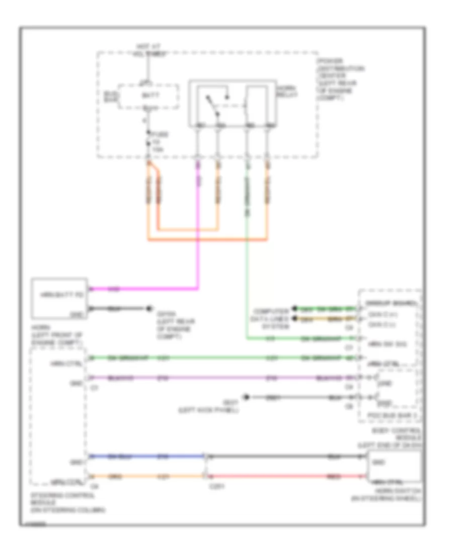
HORN
Horn Wiring Diagram for Fiat 500 Abarth 2013
List of elements for Horn Wiring Diagram for Fiat 500 Abarth 2013:

AIR CONDITIONINGANTI-THEFTBODY CONTROL MODULESCOMPUTER DATA LINESCOOLING FANANTI-LOCK BRAKESCRUISE CONTROLHEADLIGHTSDEFOGGERSELECTRONIC POWER STEERINGENGINE PERFORMANCEEXTERIOR LIGHTSINSTRUMENT CLUSTERNAVIGATIONINTERIOR LIGHTSHORNPOWER DISTRIBUTIONPOWER DOOR LOCKSGROUND DISTRIBUTIONPOWER TOP/SUNROOFPOWER MIRRORSPOWER SEATSSHIFT INTERLOCKPOWER WINDOWSSTARTING/CHARGINGRADIOTRUNK, TAILGATE, FUEL DOORWARNING SYSTEMSSUPPLEMENTAL RESTRAINTSTRANSMISSIONWIPER/WASHER