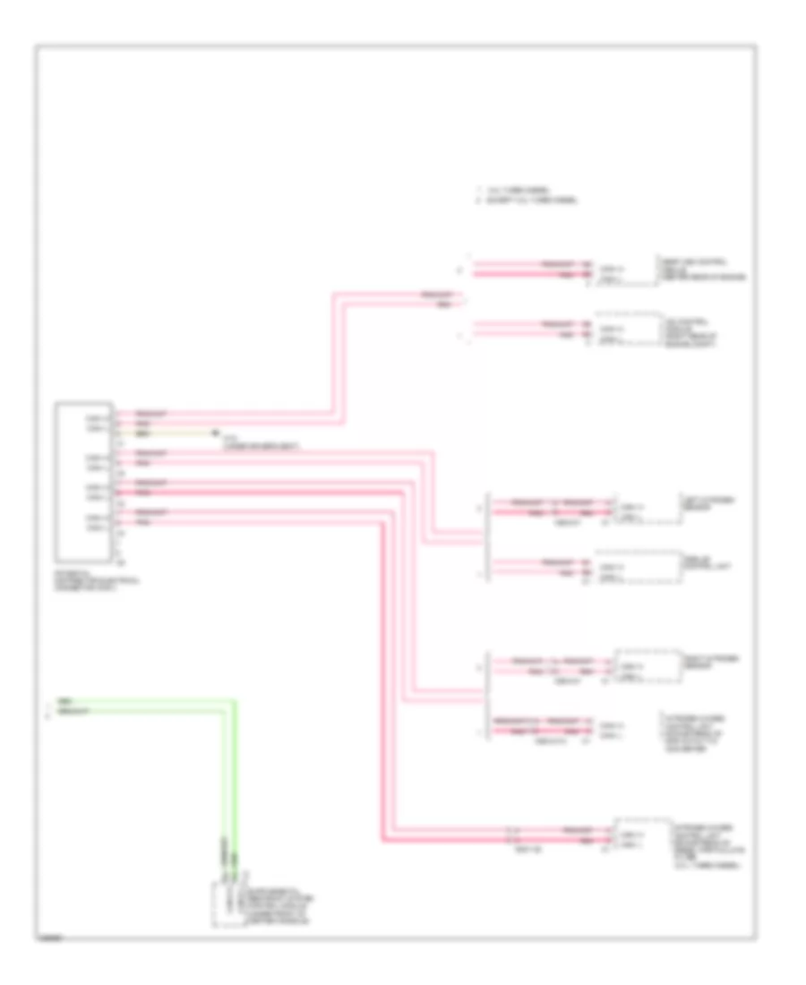
COMPUTER DATA LINES
Data Link Connector Wiring Diagram for Mercedes-Benz E350 2012
 https://portal-diagnostov.com/license.html
Automotive Electricians Portal FZCO
Automotive Electricians Portal FZCO
https://portal-diagnostov.com/license.html
https://portal-diagnostov.com/license.html
Automotive Electricians Portal FZCO
Automotive Electricians Portal FZCO
List of elements for Data Link Connector Wiring Diagram for Mercedes-Benz E350 2012:
- 31e
- C15h
- C19i
- C22i
- Can d h
- Can d l
- Coupe
- Diagnostic connector (under left side of dash)
- Driver side sam control module w/ fuse/ relay module
- Electronic stability program control unit (w/ esp basic) premium electronic stability program control unit (w/ esp premium) (left side of engine compt)
- Fuse 7.5a 5a
- Hot w/ quiescent current cutout relay energized
- Power distribution system
- Rear sam control module w/ fuse/ relay module (in spare wheelwell)
- Sedan
- W/ esp basic
- W/ esp premium
- W15/5 (coupe) w15/2 (sedan) (coupe: left front footwell)
- W16/5 (left rear of engine compt)
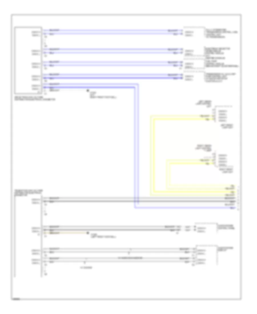
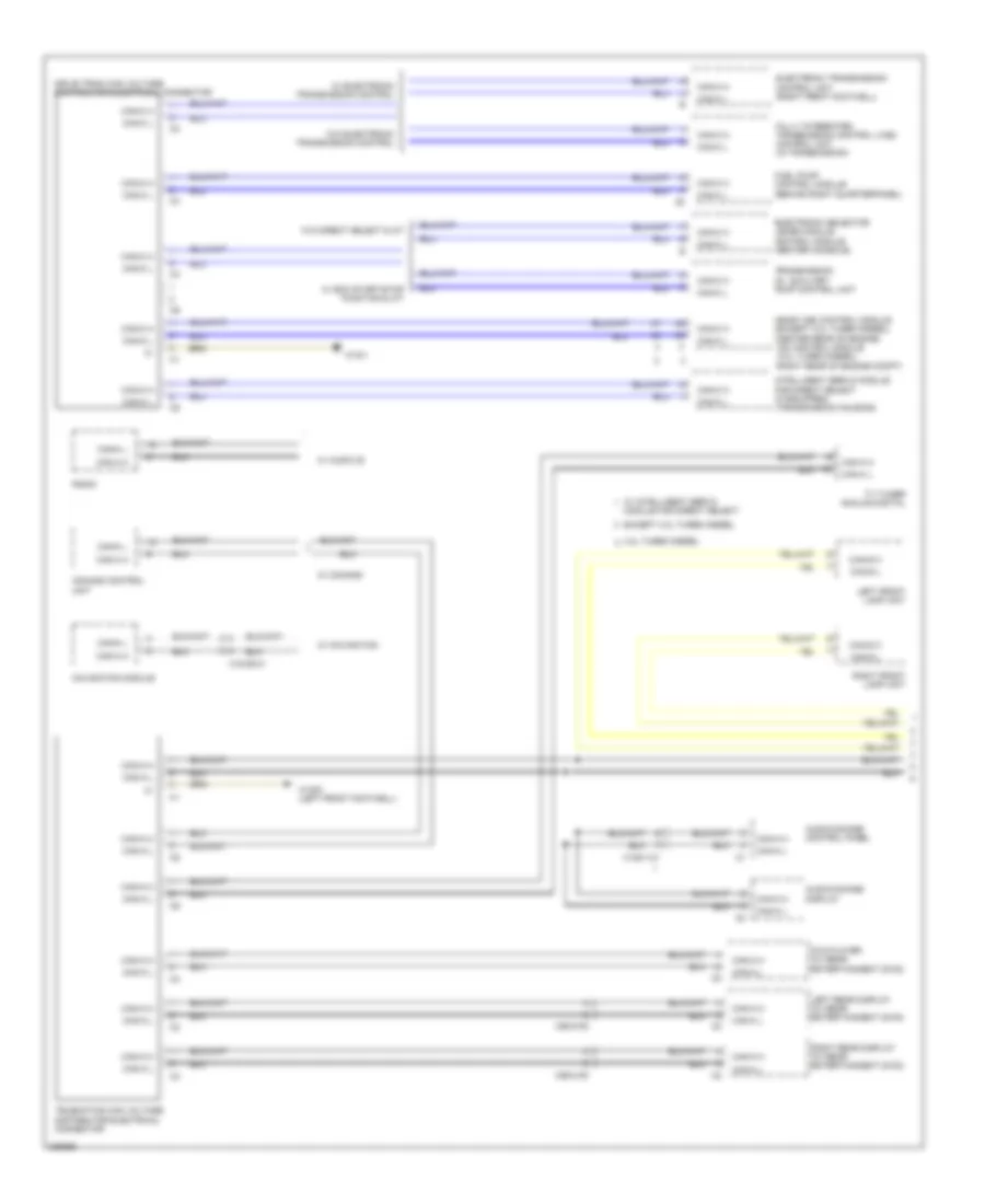
High/Low Bus Wiring Diagram, Coupe (1 of 4) for Mercedes-Benz E350 2012
List of elements for High/Low Bus Wiring Diagram, Coupe (1 of 4) for Mercedes-Benz E350 2012:
- Audio/comand control panel
- Audio/comand display
- Can-a h
- Can-a l
- Can-c h
- Can-c l
- Can-g h
- Can-g l
- Drive train can voltage distributor electrical connector
- Electronic selector lever module control module (a/t) (center console)
- Fuel pump control module (behind right quarterpanel)
- Fully integrated transmission control (vgs) control unit (in transmission)
- Left front lamp unit
- Left xenon lamp control unit
- Right front lamp unit
- Right xenon light control unit
- Telematics can voltage distributor electrical connector
- Transmission oil auxiliary pump control unit (w/ eco start/stop function & a/t)
- W/ audio 20 & audio 50
- W/ comand
- W15/6 (left front footwell)
- W15/8 (m/t) (right front footwell)
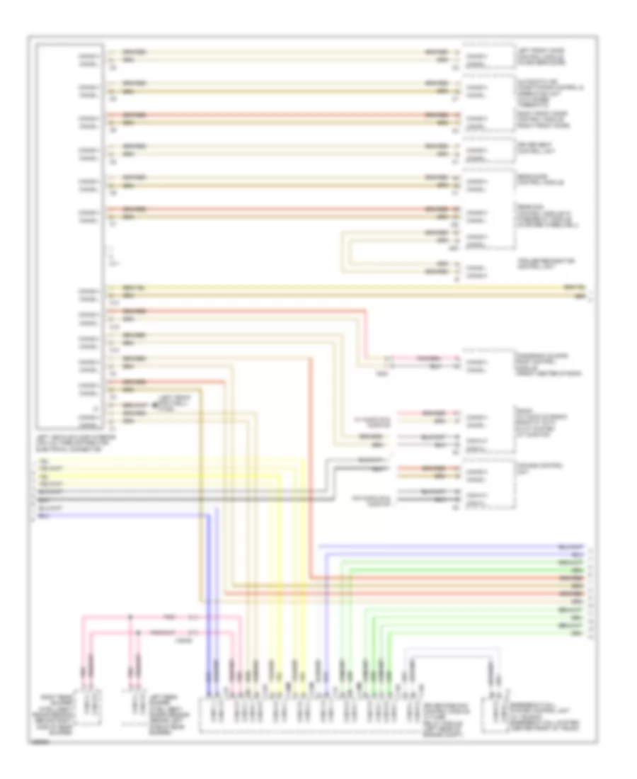
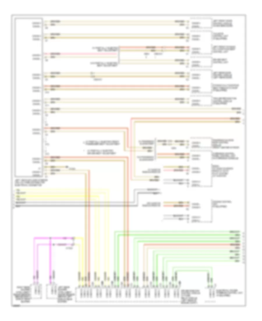
High/Low Bus Wiring Diagram, Coupe (2 of 4) for Mercedes-Benz E350 2012
List of elements for High/Low Bus Wiring Diagram, Coupe (2 of 4) for Mercedes-Benz E350 2012:
- (left front footwell) w15/6
- Automatic air conditioning control & operating unit (2 & 3 zones thermatic)
- C10
- C10i
- C11
- C12
- C13
- C18m
- C19i
- C20m
- C21m
- C22i
- C2i
- C4i
- C5h
- C9i
- Can-a h
- Can-a l
- Can-b h
- Can-b l
- Can-c h
- Can-c l
- Can-d h
- Can-d l
- Can-e h
- Can-e l
- Can-g h
- Can-g l
- Comand control unit
- Driver seat control unit
- Driver side sam control module w/ fuse/ relay module (left rear of engine compt)
- Emergency call system control unit (w/ teleaid emergency call system) (center front of trunk)
- Left front door control module (in driver's door)
- Left rear bumper intelligent radar sensor (behind left side of rear bumper)
- Left vehicle floor interior can voltage distributor electrical connector
- Panoramic sliding roof control module (front center of roof)
- Pnk
- Radio (w/ audio 20 radio) radio w/ auto pilot system (w/ audio 50)
- Rear door control module
- Rear sam control module w/ fuse/relay module (in spare wheelwell)
- Right front door control module (right front door)
- Right rear bumper intelligent radar sensor (behind right side of rear bumper)
- Trailer recognition control unit
- W/ audio 20 & audio 50
- W/o audio 20 & audio 50
- X204
- X35/28
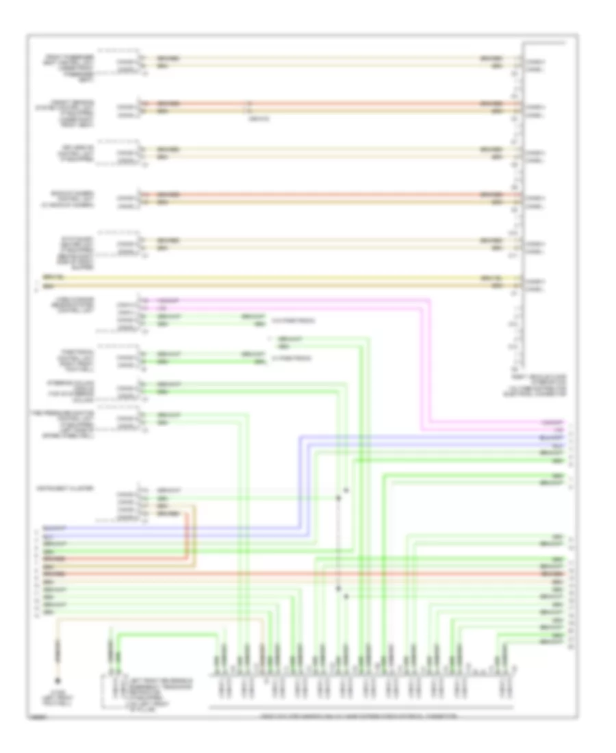
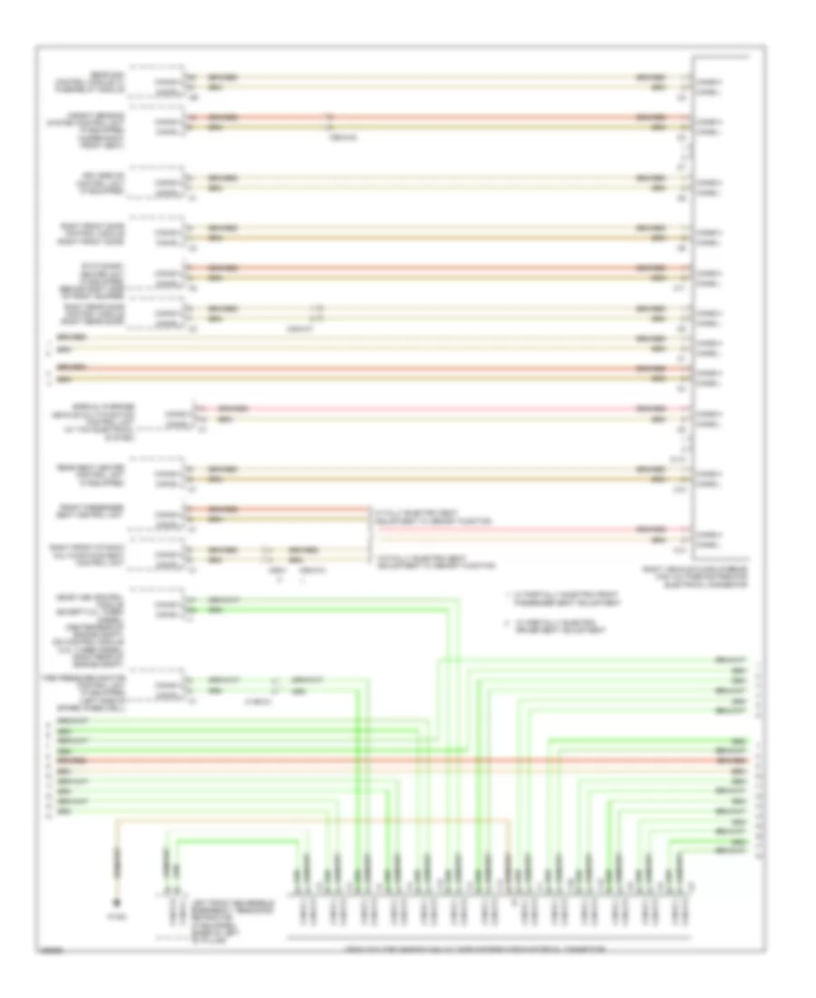
High/Low Bus Wiring Diagram, Coupe (3 of 4) for Mercedes-Benz E350 2012
List of elements for High/Low Bus Wiring Diagram, Coupe (3 of 4) for Mercedes-Benz E350 2012:
- Backup camera control unit (w/ backup camera)
- C10
- C11
- C12
- C13
- Can-b h
- Can-b l
- Can-e h
- Can-e l
- Can-h h
- Can-h l
- Front passenger seat control unit (under front passenger seat)
- Instrument cluster
- Keyless go control unit (if equipped)
- Left front reversible emergency tensioning retractor (if equipped) (on left front "b" pillar)
- Parktronic control unit (right front footwell)
- Right vehicle floor interior can voltage distributor electrical connector
- Stationary heater unit (if equipped) (behind right side of front bumper)
- Steering column module (top of steering column)
- Tire pressure monitor control unit (if equipped) (left side of spare wheelwell)
- Vehicle floor chassis can voltage distributor electrical connector
- Video & radar sensor system control unit
- W/ parktronic
- W/o parktronic
- W15/6 (left front footwell)
- Weight sensing system control unit (if equipped) (under right front seat)
- X55/4-c2
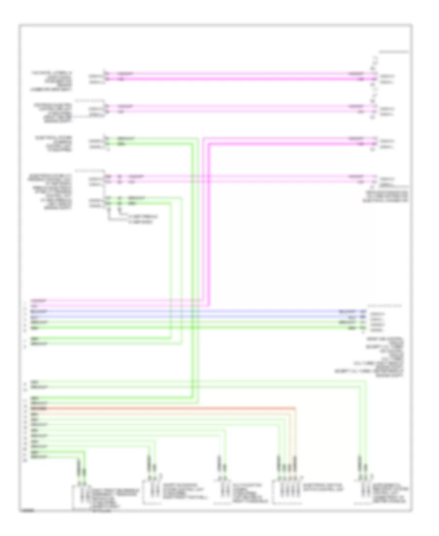
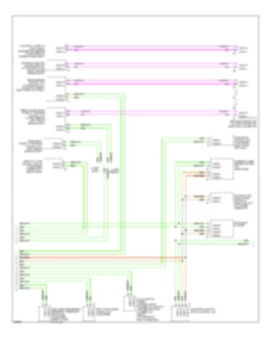
High/Low Bus Wiring Diagram, Coupe (4 of 4) for Mercedes-Benz E350 2012
List of elements for High/Low Bus Wiring Diagram, Coupe (4 of 4) for Mercedes-Benz E350 2012:
- Adaptive damping system control unit (if equipped) (right front footwell)
- Can-b h
- Can-b l
- Can-c h
- Can-c l
- Can-e h
- Can-e l
- Can-h h
- Can-h l
- Distronic electric controller unit (if equipped) (front center engine compt)
- Electrical power steering control unit (if equipped)
- Electronic ignition switch control unit
- Electronic stability program control unit (w/ esp basic) premium electronic stability program control unit (w/ esp premium) (left side of engine compt)
- Me-sfi (me) control module (except 3.0l turbo) cdi control module (3.0l turbo) (3.0l turbo: right rear of engine compt) (except 3.0l turbo: center rear of engine compt)
- Multi-function camera (if equipped) (top center of front windshield)
- Right front reversible emergency tensioning retractor (if equipped) (base of right "b" pillar)
- Vehicle dynamics can voltage distributor electrical connector
- W/ esp basic
- W/ esp premium
- Yaw rate, lateral & longitudinal acceleration sensor (under driver's seat)
High/Low Bus Wiring Diagram, Sedan (1 of 5) for Mercedes-Benz E350 2012
List of elements for High/Low Bus Wiring Diagram, Sedan (1 of 5) for Mercedes-Benz E350 2012:
- 3.0l turbo diesel
- Audio/comand control panel
- Audio/comand display
- Can-a h
- Can-a l
- Can-c h
- Can-c l
- Can-g h
- Can-g l
- Comand control unit
- Drive train can voltage distributor electrical connector
- Dvd player (w/ rear entertainment (dvd))
- Electronic selector lever module control module (center console)
- Electronic transmission control unit (right front footwell)
- Except 3.0l turbo diesel
- Fuel pump control module (behind right quarterpanel)
- Fully integrated transmission control (vgs) control unit (in transmission)
- Intelligent servo module for direct select (if equipped) (transmission housing)
- Left front lamp unit
- Left rear display (w/ rear entertainment (dvd))
- Me-sfi (me) control module (except 3.0l turbo diesel) (center rear of engine) cdi control module (3.0l turbo diesel) (right rear of engine compt)
- Module for direct select
- Navigation module
- Radio
- Right front lamp unit
- Right rear display (w/ rear entertainment (dvd))
- Telematics can voltage distributor electrical connector
- Transmission oil auxiliary pump control unit
- Tv tuner analog digital
- W/ audio 20
- W/ comand
- W/ eco start/stop function & a/t
- W/ electronic transmission control
- W/ intelligent servo
- W/ navigation
- W/o direct select & a/t
- W/o electronic transmission control
- W15/1
- W15/5 (left front footwell)
- X138/1-c1
- X18/35-c1
- X55/3-c9
- X55/4-c9
High/Low Bus Wiring Diagram, Sedan (2 of 5) for Mercedes-Benz E350 2012
List of elements for High/Low Bus Wiring Diagram, Sedan (2 of 5) for Mercedes-Benz E350 2012:
- C10
- C11
- C11c
- C12
- C13
- C18m
- C19i
- C20m
- C21m
- C22i
- C7i
- Can-a h
- Can-a l
- Can-b h
- Can-b l
- Can-d h
- Can-d l
- Can-e h
- Can-e l
- Can-g h
- Can-g l
- Comand control unit (if equipped)
- Driver seat control unit
- Driver side sam control module w/ fuse/ relay module (left rear of engine compt)
- Dynamic multicontour seat pneumatic pump (if equipped)
- Electrical power steering control unit (if equipped)
- Left front door control module (in driver's door)
- Left front dynamic multicontour seat control unit
- Left rear bumper intelligent radar sensor (behind left side of rear bumper)
- Left rear door control module (left rear door)
- Left vehicle floor interior can voltage distributor electrical connector
- Overhead control panel control unit (in overhead console)
- Panoramic sliding roof control module (front center of roof)
- Radio (w/ audio 20 radio) radio w/ auto pilot system (w/ audio 50)
- Right rear bumper intelligent radar sensor (behind right side of rear bumper)
- Tailgate control unit (if equipped)
- Trailer recognition control module (if equipped)
- W/ audio 20 radio & radio 50
- W/ panoramic sliding roof
- W/ partially electric driver seat adjustment
- W/ partially electric front passenger seat adjustment
- W/ partially electric seat adjustment
- W/o audio 20 radio & radio 50
- W/o panoramic sliding roof
- W/o partially electric seat adjustment
- W15/2
- X172/2
- X204
- X35/3-c1
- X55/3-c1
- X55/4
High/Low Bus Wiring Diagram, Sedan (3 of 5) for Mercedes-Benz E350 2012
List of elements for High/Low Bus Wiring Diagram, Sedan (3 of 5) for Mercedes-Benz E350 2012:
- C10
- C11
- C110
- C12
- C13
- C9i
- Can-b h
- Can-b l
- Can-e h
- Can-e l
- Front passenger seat control unit
- Keyless go control unit (if equipped)
- Left front reversible emergency tensioning retractor (if equipped) (base of left "b" pillar)
- Me-sfi (me) control module (except 3.0l turbo diesel) (center rear of engine compt) cdi control module (3.0l turbo diesel) (right rear of engine compt)
- Rear sam control module w/ fuse/relay module
- Rear seat heater control unit (if equipped)
- Right front door control module (right front door)
- Right front dynamic multicontour seat control unit
- Right rear door control module (right rear door)
- Right vehicle floor interior can voltage distributor electrical connector
- Special purpose vehicle multi-function control unit (w/ taxi electrical system)
- Stationary heater unit (if equipped) (behind right side of front bumper)
- Tire pressure monitor control unit (if equipped) (left side of spare wheelwell)
- Vehicle floor chassis can voltage distributor electrical connector
- W/ fully electric seat adjustment w/ memory function
- W/ partially electric driver seat adjustment
- W/ partially electric front passenger seat adjustment
- W/o fully electric seat adjustment w/ memory function
- W15/2
- Weight sensing system control unit (if equipped) (under right front seat)
- X1/60-c1
- X35/4-c1
- X55/3
- X55/4-c1
- X55/4-c2
High/Low Bus Wiring Diagram, Sedan (4 of 5) for Mercedes-Benz E350 2012
List of elements for High/Low Bus Wiring Diagram, Sedan (4 of 5) for Mercedes-Benz E350 2012:
- Airmatic w/ ads control module (if equipped) (under right side of dash)
- Automatic air conditioning control & operating unit (2 & 3 zones thermatic)
- Can-b h
- Can-b l
- Can-e h
- Can-e l
- Can-h h
- Can-h l
- Distronic electric controller unit (w/ distronic plus) (front center engine compt)
- Electronic ignition switch control unit
- Electronic stability program control unit (left side of engine compt)
- Instrument cluster
- Multi-function camera (interior lights package, w/automatic lane recognition & w/ speed limit assist) (top center of front windshield)
- Night vision assist control unit (if equipped)
- Parktronic control unit (if equipped) (right front footwell)
- Premium electronic stability program control unit (w/ esp premium) (left side of engine compt)
- Radar sensor control unit (w/ distronic & w/ blind spot assist) (right front footwell)
- Right front reversible emergency tensioning retractor (if equipped) (base of right "b" pillar)
- Steering wheel heater control unit (ifequipped)
- Vehicle dynamics can voltage distributor electrical connector
- W/ esp basic
- W/ esp premium
- Yaw rate, lateral & longitudinal acceleration sensor (w/ esp premium) (under driver's seat)
High/Low Bus Wiring Diagram, Sedan (5 of 5) for Mercedes-Benz E350 2012
List of elements for High/Low Bus Wiring Diagram, Sedan (5 of 5) for Mercedes-Benz E350 2012:
- 3.0l turbo diesel
- Can-e h
- Can-e l
- Can-i h
- Can-i l
- Cdi control module (right rear of engine compt)
- Except 3.0l turbo diesel
- Left nitrogen sensor
- Me-sfi (me) control module (center rear of engine)
- Nitrogen oxides control unit downstream of diesel particulate filter (3.0 l turbo diesel)
- Nitrogen oxides control unit downstream of scr catalytic converter
- Pnk
- Potential distributor electrical connector (can i)
- Right nitrogen sensor
- W18 (under driver's seat)
- X86/1-c2
- X86/3-c1
- X86/4-c1
- X86/4-c1a

 Čeština
 Deutsch
 Ελληνικά
 English
 English
 Español
 Suomi
Suomi Français
 Français
 עברית
עברית Hrvatski
 Magyar
 Italiano
 日本語
日本語 한국어
한국어 Nederlands
 Polski
 Português
 Português
 Română
 Русский
 Slovenčina
 Slovenščina
 Svenska
 Türkçe
 中文 (中国)