SUPPLEMENTAL RESTRAINTS
Supplemental Restraint Wiring Diagram for Chevrolet Silverado 3500 2002
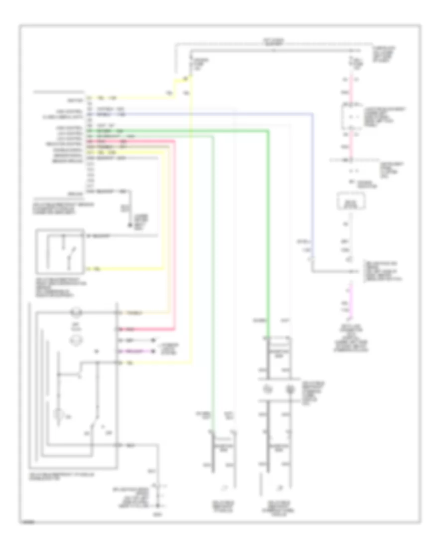
List of elements for Supplemental Restraint Wiring Diagram for Chevrolet Silverado 3500 2002:
- (under driver seat) g304
- A10
- A11
- A12
- A13
- A14
- A15
- A16
- A17
- A18
- Air bag fuse 15a
- Air bag indicator
- Class 2 serial data
- Data link connector (dlc) (partial) (under left side of dash, below steering column)
- Disable signal
- Fuse block (on lower left side of dash)
- G203
- Ground
- High control
- Hot in run & start
- Ign 1 fuse 10a
- Ignition
- Indicator control
- Inflatable restraint front end discriminating sensor (on underside of radiator support)
- Inflatable restraint i/p module disable switch
- Inflatable restraint ip module
- Inflatable restraint sensing & diagnostic module (under driver's seat)
- Inflatable restraint steering wheel module
- Inflatable restraint steering wheel module coil
- Instrument panel cluster (ipc)
- Interior lights system
- Junction block-body (under left side of dash, near left kick panel)
- Low control
- Nca
- Off
- Pnk
- Sensor ground
- Sensor signal
- Shorting bar
- Solid state
- Splice pack 205 (sp205) (on left side of dash, behind headlamp switch)
- Splice pack sp203 (sp203) (on top left side of dash, near "a" pillar)
 Čeština
 Deutsch
 Ελληνικά
 English
 English
 Español
 Suomi
Suomi Français
 Français
 עברית
עברית Hrvatski
 Magyar
 Italiano
 日本語
日本語 한국어
한국어 Nederlands
 Polski
 Português
 Português
 Română
 Русский
 Slovenčina
 Slovenščina
 Svenska
 Türkçe
 中文 (中国)
 Dansk
Dansk