NAVIGATION
Blind Spot Monitoring Wiring Diagram for Toyota Tundra SR5 2014
 https://portal-diagnostov.com/license.html
Automotive Electricians Portal FZCO
Automotive Electricians Portal FZCO
https://portal-diagnostov.com/license.html
https://portal-diagnostov.com/license.html
Automotive Electricians Portal FZCO
Automotive Electricians Portal FZCO
List of elements for Blind Spot Monitoring Wiring Diagram for Toyota Tundra SR5 2014:
- Aj2
- Bind
- Blb
- Blgd
- Blind spot monitor main switch (warning canceling switch assembly)
- Brb
- Brgd
- Bsl+
- Bsr+
- Bssw
- Buz
- Bzn
- Bzp
- Ca1n
- Ca1p
- Ca2n
- Ca2p
- Computer data lines system
- D56
- Driver side j/b (left end of dash)
- Ecu ig 1 fuse 7.5a
- Hot in on or start
- Ill+
- Ill-
- Indicator monitor blind spot
- Interior lights system
- J/c j72 & j73 (center of dash)
- J1 (left kick panel)
- J3 (right kick panel)
- J72
- J73
- Left blind spot monitor sensor (left corner of rear bumper)
- Left outer rear view mirror
- Mj2
- Mlp-
- Nj2
- Omil
- Omir
- Pj2
- Pnk
- R1 (rear of right frame member)
- Ra6
- Rear cross traffic alert buzzer (blind spot monitor buzzer) (if equipped) (except regular cab: left "c" pillar) (regular cab: left "b" pillar)
- Red
- Right blind spot monitor sensor (right corner of rear bumper)
- Right outer rear view mirror
- Sr1
- Sr2
- W/ memory
- W/o memory
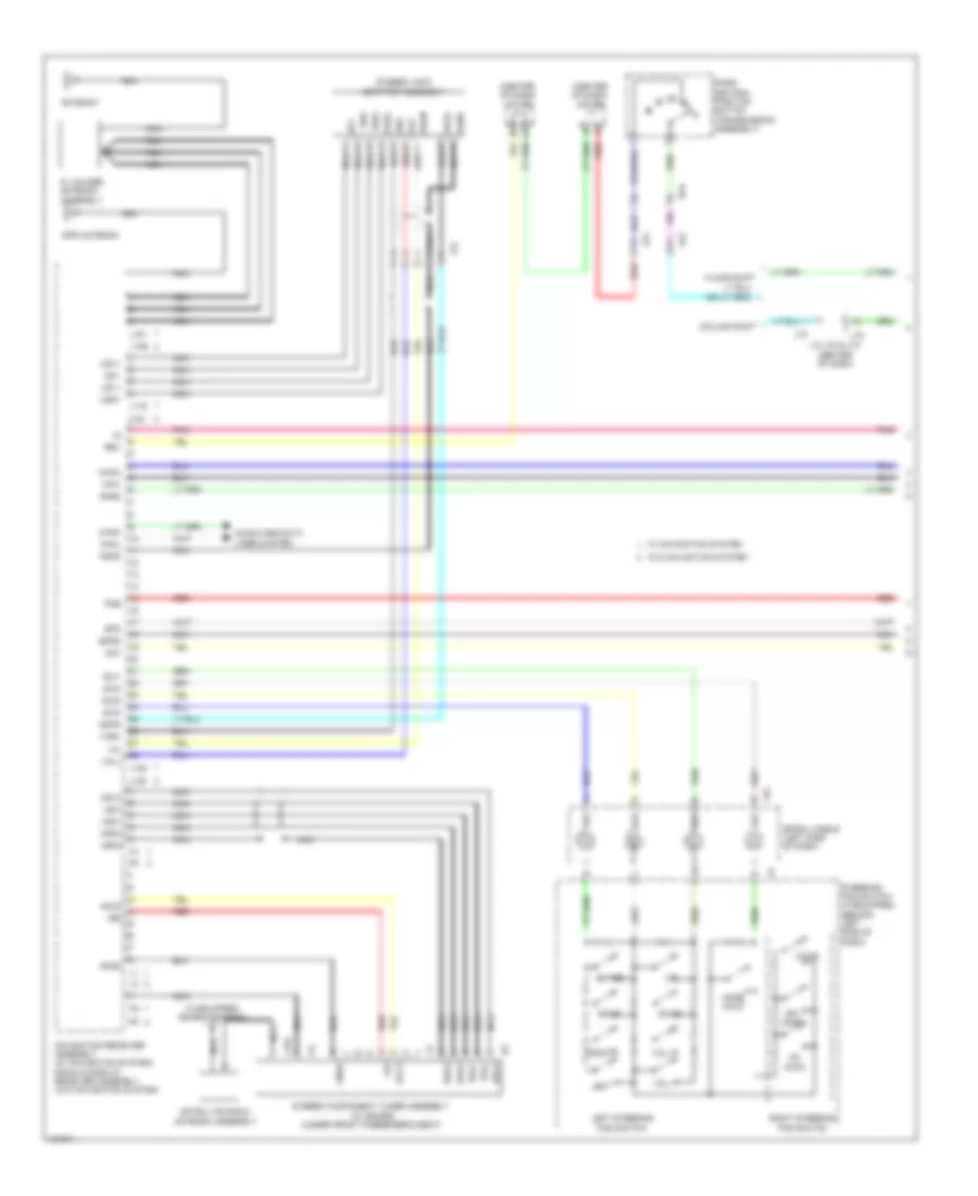
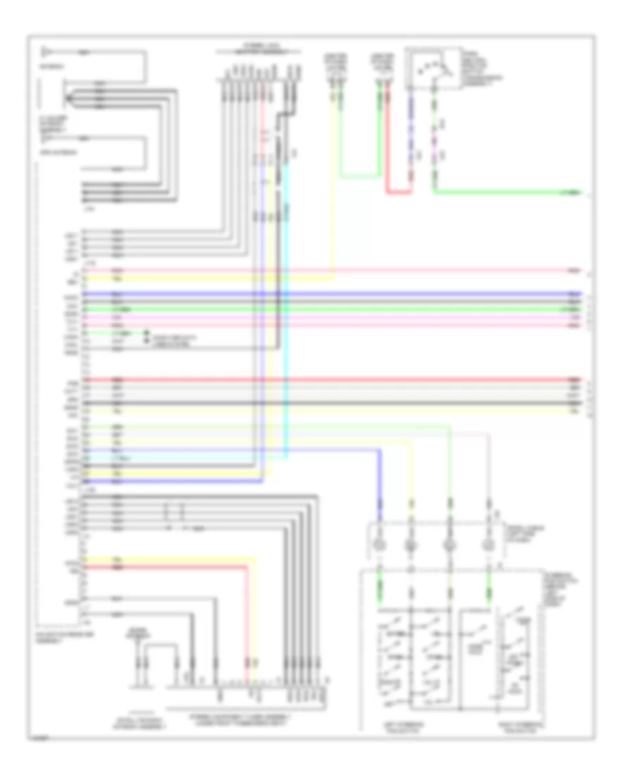
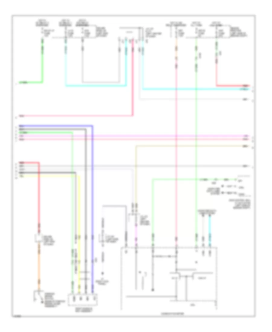
Navigation Wiring Diagram, with Built-in Amplifier (1 of 3) for Toyota Tundra SR5 2014
List of elements for Navigation Wiring Diagram, with Built-in Amplifier (1 of 3) for Toyota Tundra SR5 2014:
- (center of dash) j/c j65
- (center of dash) j/c j66
- (if equipped) sdars antenna
- +b2
- Acc2
- Adpg
- Agnd
- Aj2
- Aj4
- Alo
- Antenna
- Aro
- Asgn
- Au1
- Au2
- Au3
- Auxo
- Back
- Canh
- Canl
- Column shift
- Computer data lines system
- Da4
- Down
- Eau
- Enter
- Floor shift
- Gnd2
- Gps antenna
- J/c j72 & j73 (center of dash)
- J116
- J122
- J135
- J139
- J151
- J154
- J155
- J45
- J72
- J73
- Jj2
- Left
- Left steering pad switch
- Macc
- Min+
- Min-
- Mode hold
- Navigation receiver assembly (w/ navigation system) radio & display receiver assembly (w/o navigation system)
- Nca
- Off hook
- On hook
- Park/ neutral position switch (transmission assembly)
- Pkb
- Pnk
- Red
- Rev
- Right
- Right steering pad switch
- Satellite radio antenna assembly
- Sgnd
- Sns2
- Spd
- Spiral cable (left side of dash)
- Steering pad switch (if equipped) (behind left side of dash)
- Stereo component tuner assembly (w/ sdars) (under front passenger's seat)
- Stereo jack adapter assembly
- Sw1
- Sw2
- Sw3
- Swg
- Udo+
- Udo-
- Ugd1
- Ugd4
- Ujsg
- Up1
- Us1+
- Us1-
- Us4+
- Us4-
- Usg4
- Usv1
- Usv4
- Va-
- Val+
- Var+
- Voice
- Vol+
- Vol-
- W/ holder antenna assembly
- W/ navigation system
- W/o navigation system
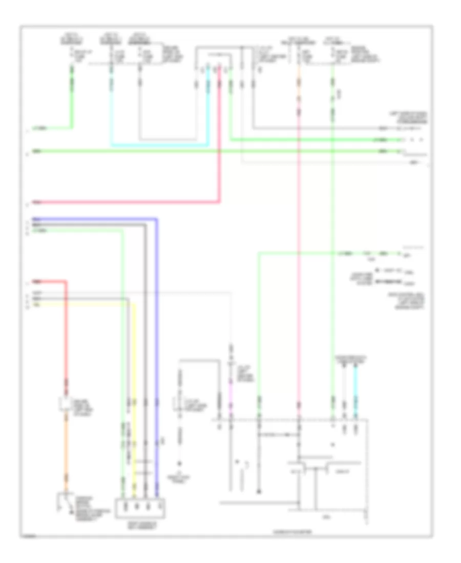
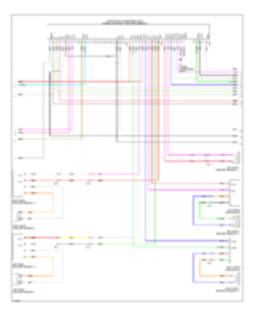
Navigation Wiring Diagram, with Built-in Amplifier (2 of 3) for Toyota Tundra SR5 2014
List of elements for Navigation Wiring Diagram, with Built-in Amplifier (2 of 3) for Toyota Tundra SR5 2014:
- (left side of dash) (column shift) diode (ignition)
- 5v ic
- Acc
- Acc fuse 7.5a
- Aj10
- Aj9
- B11
- Bk/up lp fuse 10a
- Can i/f
- Canh
- Canl
- Combination meter
- Computer data lines system
- Cpu
- D55
- D65
- Driver side j/b (left end of dash)
- Engine room r/b (left side of engine compt)
- Hot at all times
- Hot w/ acc relay energized
- Hot w/ ig1 relay 1 energized
- Hot w/ ig1 relay 2 energized
- Hot w/ ig2 relay energized
- Ig+
- J/c j61 (left side of dash)
- J/c j70 & j71 (left center of dash)
- J/c j70 (left center of dash)
- J3 (right kick panel)
- J70
- J71
- Jw1
- Lh ig fuse 7.5a
- Met fuse 7.5a
- Met-b fuse 5a
- Mi1+
- Mic-
- Nca
- Parking brake switch (base of parking brake lever assembly)
- Pnk
- Red
- Roof console box assembly
- Sgnd
- Skid control ecu w/ actuator (left side of engine compt)
- Sp1
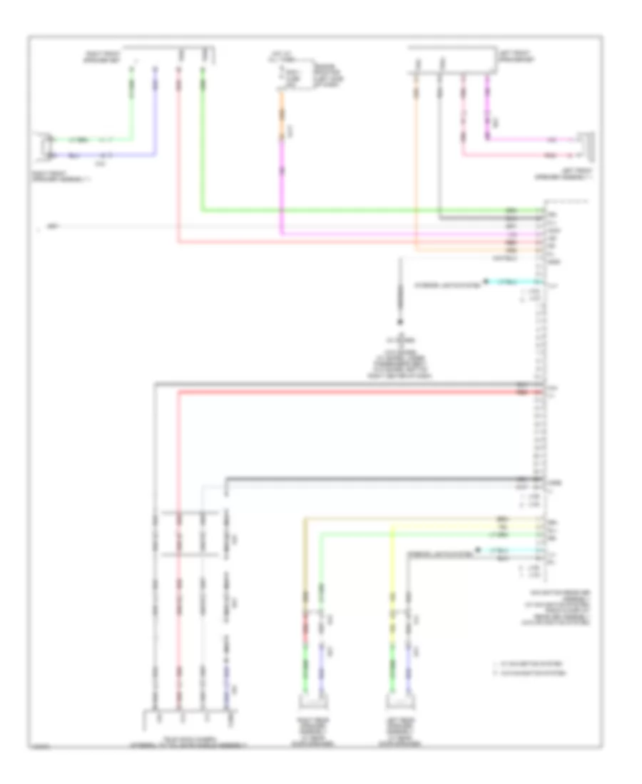
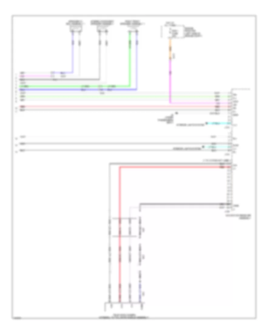
Navigation Wiring Diagram, with Built-in Amplifier (3 of 3) for Toyota Tundra SR5 2014
List of elements for Navigation Wiring Diagram, with Built-in Amplifier (3 of 3) for Toyota Tundra SR5 2014:
- +b1
- Acc1
- Aj11
- Aj5
- Ca+
- Cb+
- Cgnd
- Cv+
- Cv-
- Engine room r/b (left side of dash)
- Fl+
- Fl-
- Fr+
- Fr-
- Gnd1
- Hot at all times
- Ill+
- Ill-
- Interior lights system
- J133
- J134
- J136
- J137
- J138
- J140
- J6 (w/ sdars) j5 (w/o sdars) (w/ sdars: under passenger's seat) (w/o sdars: bottom right center of dash)
- Left front speaker assembly 1
- Left front speaker set
- Left rear speaker assembly (w/ rear door speaker)
- Mj2
- Navigation receiver assembly (w/ navigation system) radio & display receiver assembly (w/o navigation system)
- Nca
- Nj3
- Op1
- Oq1
- Pj1
- Pnk
- Qj2
- Ra1
- Rad 1 fuse 20a
- Red
- Right front speaker assembly 1
- Right front speaker set
- Right rear speaker assembly (w/ rear door speaker)
- Rl+
- Rl-
- Rr+
- Rr-
- Television camera (integral to tail gate handle assembly)
- Twl+
- Twl-
- Twr+
- Twr-
- W/ navigation system
- W/o navigation system
- Xr1
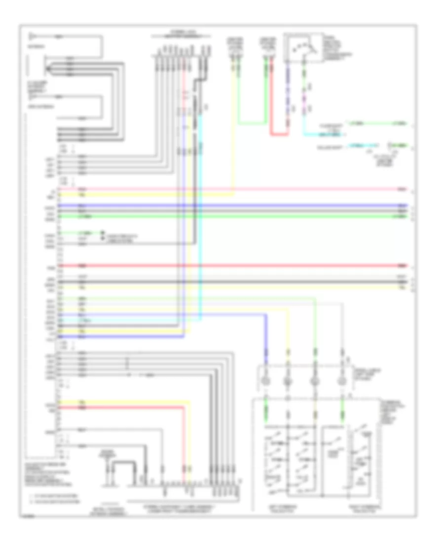
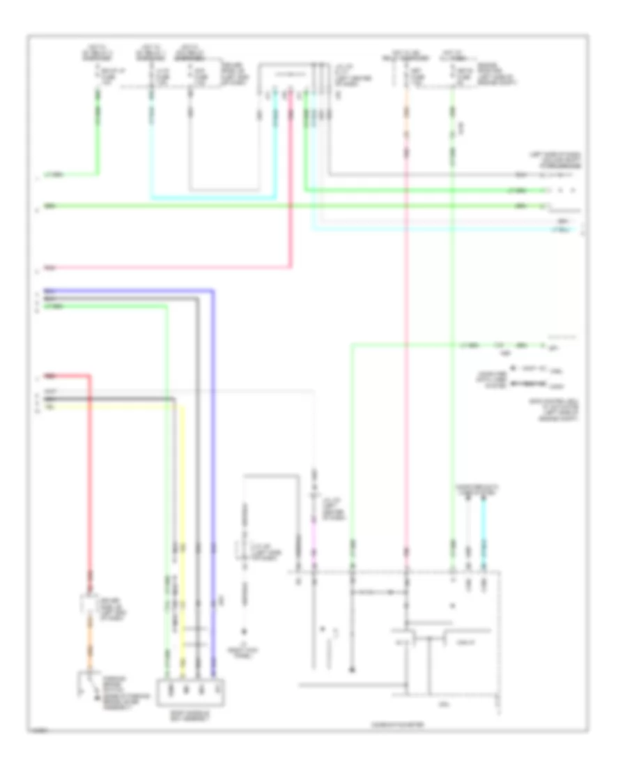
Navigation Wiring Diagram, with Separate Amplifier & JBL (1 of 4) for Toyota Tundra SR5 2014
List of elements for Navigation Wiring Diagram, with Separate Amplifier & JBL (1 of 4) for Toyota Tundra SR5 2014:
- (center of dash) j/c j65
- (center of dash) j/c j66
- +b2
- Acc2
- Adpg
- Agnd
- Aj2
- Aj4
- Alo
- Antenna
- Aro
- Asgn
- Au1
- Au2
- Au3
- Auxo
- Back
- Canh
- Canl
- Computer data lines system
- Da4
- Down
- Eau
- Enter
- Gnd2
- Gps antenna
- J116
- J135
- J151
- J154
- J45
- Jj2
- Left
- Left steering pad switch
- Macc
- Min+
- Min-
- Mode hold
- Mut1
- Navigation receiver assembly
- Nca
- Off hook
- On hook
- Park/ neutral position switch (transmission assembly)
- Pkb
- Pnk
- Red
- Rev
- Right
- Right steering pad switch
- Satellite radio antenna assembly
- Sdars antenna
- Sgnd
- Sns2
- Spd
- Spiral cable (left side of dash)
- Steering pad switch (behind left side of dash)
- Stereo component tuner assembly (under front passenger's seat)
- Stereo jack adapter assembly
- Sw1
- Sw2
- Sw3
- Swg
- Tx1+
- Tx1-
- Udo+
- Udo-
- Ugd1
- Ugd4
- Ujsg
- Up1
- Us1+
- Us1-
- Us4+
- Us4-
- Usg4
- Usv1
- Usv4
- Va-
- Val+
- Var+
- Voice
- Vol+
- Vol-
- W/ holder antenna assembly
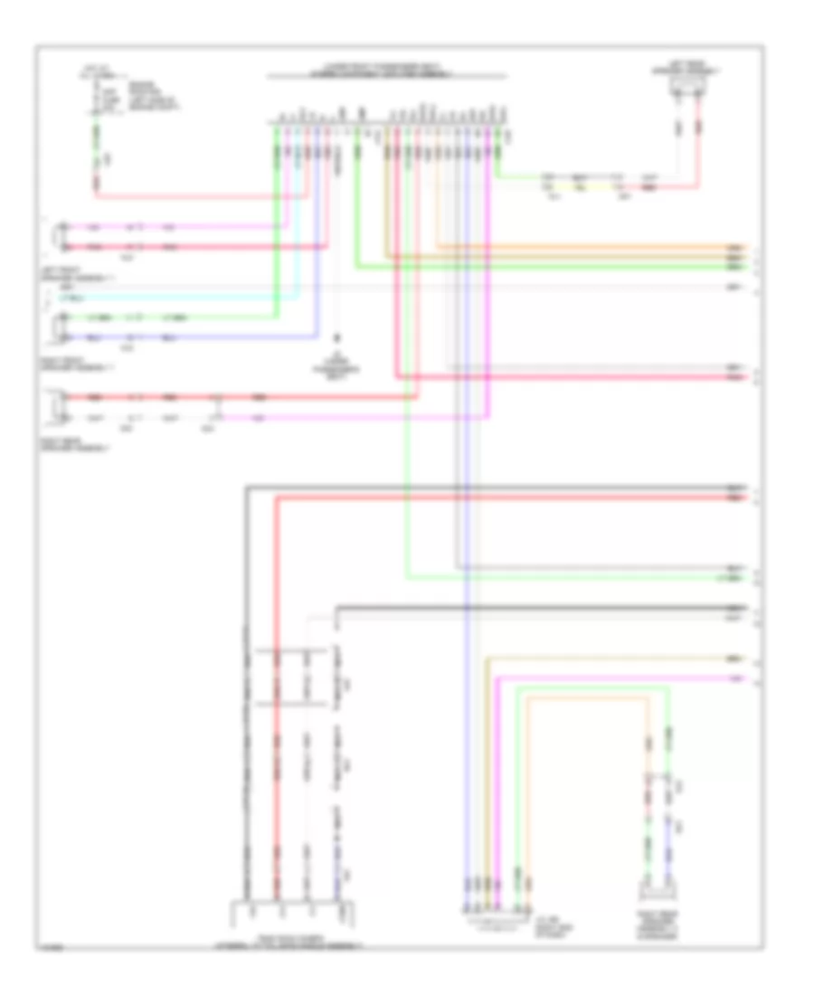
Navigation Wiring Diagram, with Separate Amplifier & JBL (2 of 4) for Toyota Tundra SR5 2014
List of elements for Navigation Wiring Diagram, with Separate Amplifier & JBL (2 of 4) for Toyota Tundra SR5 2014:
- 5v ic
- Acc
- Acc fuse 7.5a
- Ag9
- Aj10
- Aj9
- Amp fuse 30a
- B11
- Bk/up lp fuse 10a
- Can i/f
- Canh
- Canl
- Combination meter
- Computer data lines system
- Cpu
- D55
- D65
- Driver side j/b (left end of dash)
- Engine room r/b (left side of engine compt)
- Hot at all times
- Hot w/ acc relay energized
- Hot w/ ig1 relay 1 energized
- Hot w/ ig1 relay 2 energized
- Hot w/ ig2 relay energized
- Ig+
- J/c j61 (left side of dash)
- J/c j70 & j71 (left center of dash)
- J/c j70 (left center of dash)
- J3 (right kick panel)
- J70
- J71
- Jw1
- Lh ig fuse 7.5a
- Met fuse 7.5a
- Met-b fuse 5a
- Mi1+
- Mic-
- Nca
- Parking brake switch (base of parking brake lever assembly)
- Pnk
- Red
- Roof console box assembly
- Sgnd
- Skid control ecu w/ actuator (left side of engine compt)
- Sp1
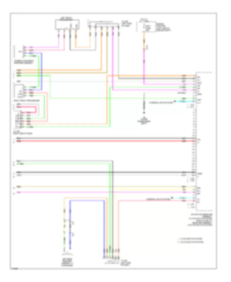
Navigation Wiring Diagram, with Separate Amplifier & JBL (3 of 4) for Toyota Tundra SR5 2014
List of elements for Navigation Wiring Diagram, with Separate Amplifier & JBL (3 of 4) for Toyota Tundra SR5 2014:
- (under front passenger's seat) stereo component amplifier assembly
- +b2
- +tw
- -tw
- Acc
- Ctr+
- Ctr-
- Fl+
- Fl-
- Fr+
- Fr-
- Gnd
- Gnd2
- Ii1+
- Ii1-
- J141
- J142
- J143
- J6 (under passenger's seat)
- Left front speaker assembly 1
- Left front speaker assembly 2
- Left front speaker set
- Left rear speaker assembly
- Left rear speaker assembly 2
- Mj2
- Mute
- Nca
- Nj3
- Op1
- Oq1
- Pj1
- Pnk
- Qj2
- Red
- Right front speaker assembly 2
- Right front speaker set
- Right rear speaker assembly
- Right rear speaker assembly 2
- Rl+
- Rl-
- Rr+
- Rr-
- Sld
- Spd
- Twl+
- Twl-
- Twr+
- Twr-
- Tx+
- Tx-
- Wf1+
- Wf1-
- Wfl+
- Wfl-
- Wfr+
- Wfr-
Navigation Wiring Diagram, with Separate Amplifier & JBL (4 of 4) for Toyota Tundra SR5 2014
List of elements for Navigation Wiring Diagram, with Separate Amplifier & JBL (4 of 4) for Toyota Tundra SR5 2014:
- (1 to 10 pins not used)
- +b1
- Acc1
- Aj11
- Aj5
- Ca+
- Cb+
- Cgnd
- Cv+
- Cv-
- Engine room r/b (left side of engine compt)
- Fl+
- Fl-
- Fr+
- Fr-
- Gnd1
- Hot at all times
- Ill+
- Ill-
- Interior lights system
- J133
- J134
- J136
- J6 (under passenger's seat)
- Mj2
- Navigation receiver assembly
- Nca
- Pj1
- Ra1
- Rad 1 fuse 20a
- Red
- Right front speaker assembly 1
- Rl+
- Rl-
- Sld2
- Speaker w/ box assembly 1
- Stereo component speaker assembly
- Television camera (integral to tail gate handle assembly)
- Xr1
Navigation Wiring Diagram, with Separate Amplifier & without JBL (1 of 4) for Toyota Tundra SR5 2014
List of elements for Navigation Wiring Diagram, with Separate Amplifier & without JBL (1 of 4) for Toyota Tundra SR5 2014:
- (center of dash) j/c j65
- (center of dash) j/c j66
- +b2
- Acc2
- Adpg
- Agnd
- Aj2
- Aj4
- Alo
- Antenna
- Aro
- Asgn
- Au1
- Au2
- Au3
- Auxo
- Back
- Canh
- Canl
- Column shift
- Computer data lines system
- Da4
- Down
- Eau
- Enter
- Floor shift
- Gnd2
- Gps antenna
- J/c j72 & j73 (center of dash)
- J116
- J122
- J135
- J139
- J151
- J154
- J155
- J45
- J72
- J73
- Jj2
- Left
- Left steering pad switch
- Macc
- Min+
- Min-
- Mode hold
- Navigation receiver assembly (w/ navigation system) radio & display receiver assembly (w/o navigation system)
- Nca
- Off hook
- On hook
- Park/ neutral position switch (transmission assembly)
- Pkb
- Pnk
- Red
- Rev
- Right
- Right steering pad switch
- Satellite radio antenna assembly
- Sdars antenna
- Sgnd
- Sns2
- Spd
- Spiral cable (left side of dash)
- Steering pad switch (behind left side of dash)
- Stereo component tuner assembly (under front passenger's seat)
- Stereo jack adapter assembly
- Sw1
- Sw2
- Sw3
- Swg
- Udo+
- Udo-
- Ugd4
- Ujsg
- Up1
- Us1+
- Us1-
- Us4+
- Us4-
- Usd1
- Usg4
- Usv1
- Usv4
- Va-
- Val+
- Var+
- Voice
- Vol+
- Vol-
- W/ holder antenna assembly
- W/ navigation system
- W/o navigation system
Navigation Wiring Diagram, with Separate Amplifier & without JBL (2 of 4) for Toyota Tundra SR5 2014
List of elements for Navigation Wiring Diagram, with Separate Amplifier & without JBL (2 of 4) for Toyota Tundra SR5 2014:
- (left side of dash) (column shift) diode (ignition)
- 5v ic
- Acc
- Acc fuse 7.5a
- Ag9
- Aj10
- B11
- Bk/up lp fuse 10a
- Can i/f
- Canh
- Canl
- Combination meter
- Computer data lines system
- Cpu
- D55
- D65
- Driver side j/b (left end of dash)
- Engine room r/b (left side of engine compt)
- Hot at all times
- Hot w/ acc relay energized
- Hot w/ ig1 relay 1 energized
- Hot w/ ig1 relay 2 energized
- Hot w/ ig2 relay energized
- Ig+
- J/c j61 (left side of dash)
- J/c j70 & j71 (left center of dash)
- J/c j70 (left center of dash)
- J3 (right kick panel)
- J70
- J71
- Jw1
- Lh ig fuse 7.5a
- Met fuse 7.5a
- Met-b fuse 5a
- Mi1+
- Mic-
- Nca
- Parking brake switch (base of parking brake lever assembly)
- Pnk
- Red
- Roof console box assembly
- Sgnd
- Skid control ecu w/ actuator (left side of engine compt)
- Sp1
Navigation Wiring Diagram, with Separate Amplifier & without JBL (3 of 4) for Toyota Tundra SR5 2014
List of elements for Navigation Wiring Diagram, with Separate Amplifier & without JBL (3 of 4) for Toyota Tundra SR5 2014:
- (under front passenger's seat) stereo component amplifier assembly
- Acc
- Aj5
- Aj9
- Amp
- Amp fuse 30a
- Cb+
- Cgnd
- Cv+
- Cv-
- Engine room r/b (left side of engine compt)
- Fl+
- Fl-
- Fr+
- Fr-
- Gnd
- Hot at all times
- J/c j69 (right end of dash)
- J144
- J145
- J6 (under passenger's seat)
- Left front speaker assembly 1
- Left rear speaker assembly
- Mj2
- Nca
- Nj3
- Op1
- Oq1
- Pj1
- Pnk
- Qj2
- Ra1
- Red
- Right front speaker assembly 1
- Right rear speaker assembly
- Right rear speaker assembly 2 (9 speaker)
- Rl+
- Rl-
- Rr+
- Rr-
- Television camera (integral to tail gate handle assembly)
- Wfl+
- Wfl-
- Wfr+
- Wfr-
- Xr1
Navigation Wiring Diagram, with Separate Amplifier & without JBL (4 of 4) for Toyota Tundra SR5 2014
List of elements for Navigation Wiring Diagram, with Separate Amplifier & without JBL (4 of 4) for Toyota Tundra SR5 2014:
- +b1
- Acc1
- Aj11
- Amp
- Ca+
- Cgnd
- Engine room r/b (left side of engine compt)
- Fl+
- Fl-
- Fr+
- Fr-
- Gnd1
- Hot at all times
- Ill+
- Ill-
- Interior lights system
- J/c j68 (left side of dash)
- J/c j69 (right end of dash)
- J133
- J134
- J136 j140
- J137
- J138
- J6 (under passenger's seat)
- Left front speaker set
- Left rear speaker assembly 2 (9 speaker)
- Navigation receiver assembly (w/ navigation system) radio & display receiver assembly (w/o navigation system)
- Nca
- Op1
- Pj1
- Pnk
- Rad 1 fuse 20a
- Red
- Ri1+
- Ri1-
- Right front speaker set
- Rl+
- Rl-
- Rr+
- Rr-
- Stereo component speaker assembly
- Twl+
- Twl-
- Twr+
- Twr-
- W/ navigation system
- W/o navigation system
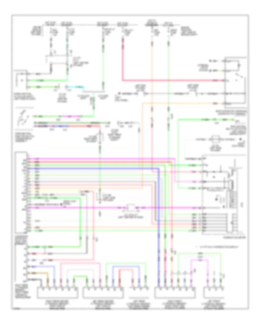
Parking Assistant Wiring Diagram for Toyota Tundra SR5 2014
List of elements for Parking Assistant Wiring Diagram for Toyota Tundra SR5 2014:
- (left end of dash) j/c j60
- (left side of dash) j/c j61
- (right kick panel) j3
- 5v ic
- 5v+b
- A45
- Ab1
- Acc fuse 7.5a
- Aj10
- Aj2
- Aj4
- Aj5
- Aj9
- Back sonar or clearance sonar switch assembly
- Bk/up lp fuse 10a
- Bof
- Bor
- Buzzer
- Ca1
- Clearance sonar ecu (right end of dash)
- Combination meter
- Cpu
- D55
- D56
- D65
- D73
- Da4
- Diode (ignition) (w/ column shift) (left side of dash)
- Display color
- Driver side j/b (left end of dash)
- Ecu
- Ecu ig 1 fuse 7.5a
- Engine room r/b (left side of engine compt)
- Hot at all times
- Hot in on or acc
- Hot in on or start
- Hot w/ ig2 relay energized
- I/f
- Ig+
- Ill+
- Ill-
- Interior
- J/c a45 & d73 (right rear of engine compt)
- J/c j61 (left side of dash)
- J/c j65 (left side of dash)
- J/c j66 (right end of dash)
- J/c j70 & j71 (left center of dash)
- J/c j72 & j73 (center of dash)
- J1 (left kick panel)
- J3 (right kick panel)
- J70
- J71
- J72
- J73
- L10
- Left front ultrasonic sensor 1 (left front end of front bumper)
- Left rear center ultrasonic sensor 1 (left side of rear bumper)
- Left rear ultrasonic sensor 1 (left rear corner of rear bumper)
- Lh ig fuse 7.5a
- Lights
- Met fuse 7.5a
- Met-b fuse 5a
- Park/neutral position switch (transmission assembly)
- Pnk
- Ra1
- Red
- Right front ultrasonic sensor 1 (right front end of front bumper)
- Right rear center ultrasonic sensor 1 (right side of rear bumper)
- Right rear ultrasonic sensor 1 (right rear corner of rear bumper)
- Skid control ecu w/ actuator (left side of engine compt)
- Sof
- Sor
- Sp1
- Spd
- Sr1
- System
- Tft
- W/ column shift
- W/ floor shift
- W/ tft multi-information display

 Čeština
 Deutsch
 Ελληνικά
 English
 English
 Español
 Suomi
Suomi Français
 Français
 עברית
עברית Hrvatski
 Magyar
 Italiano
 日本語
日本語 한국어
한국어 Nederlands
 Polski
 Português
 Português
 Română
 Русский
 Slovenčina
 Slovenščina
 Svenska
 Türkçe
 中文 (中国)