AIR CONDITIONING
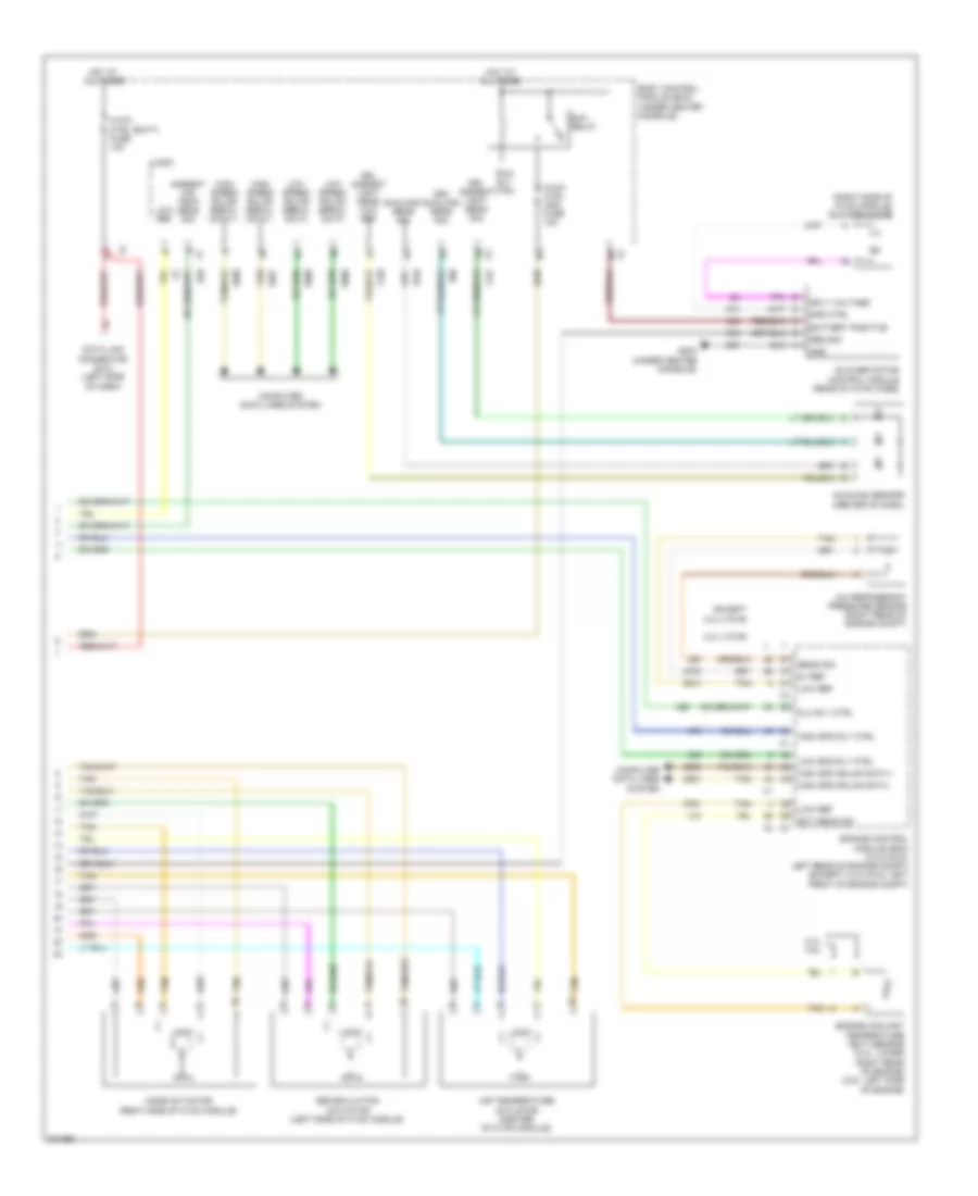
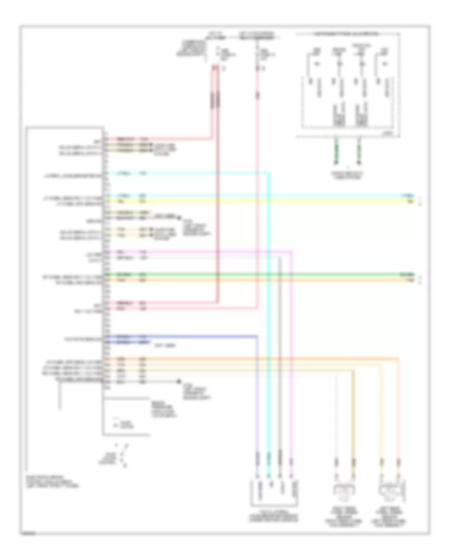
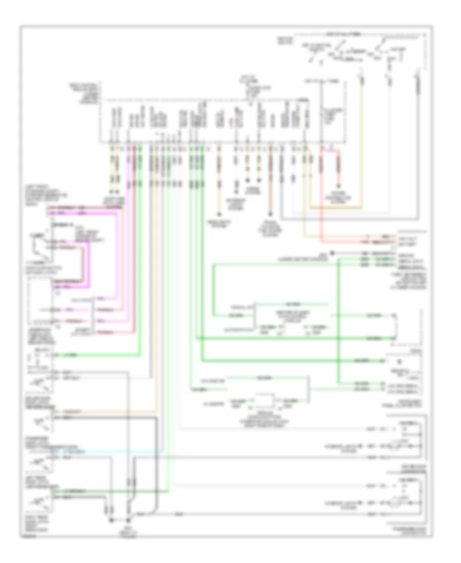
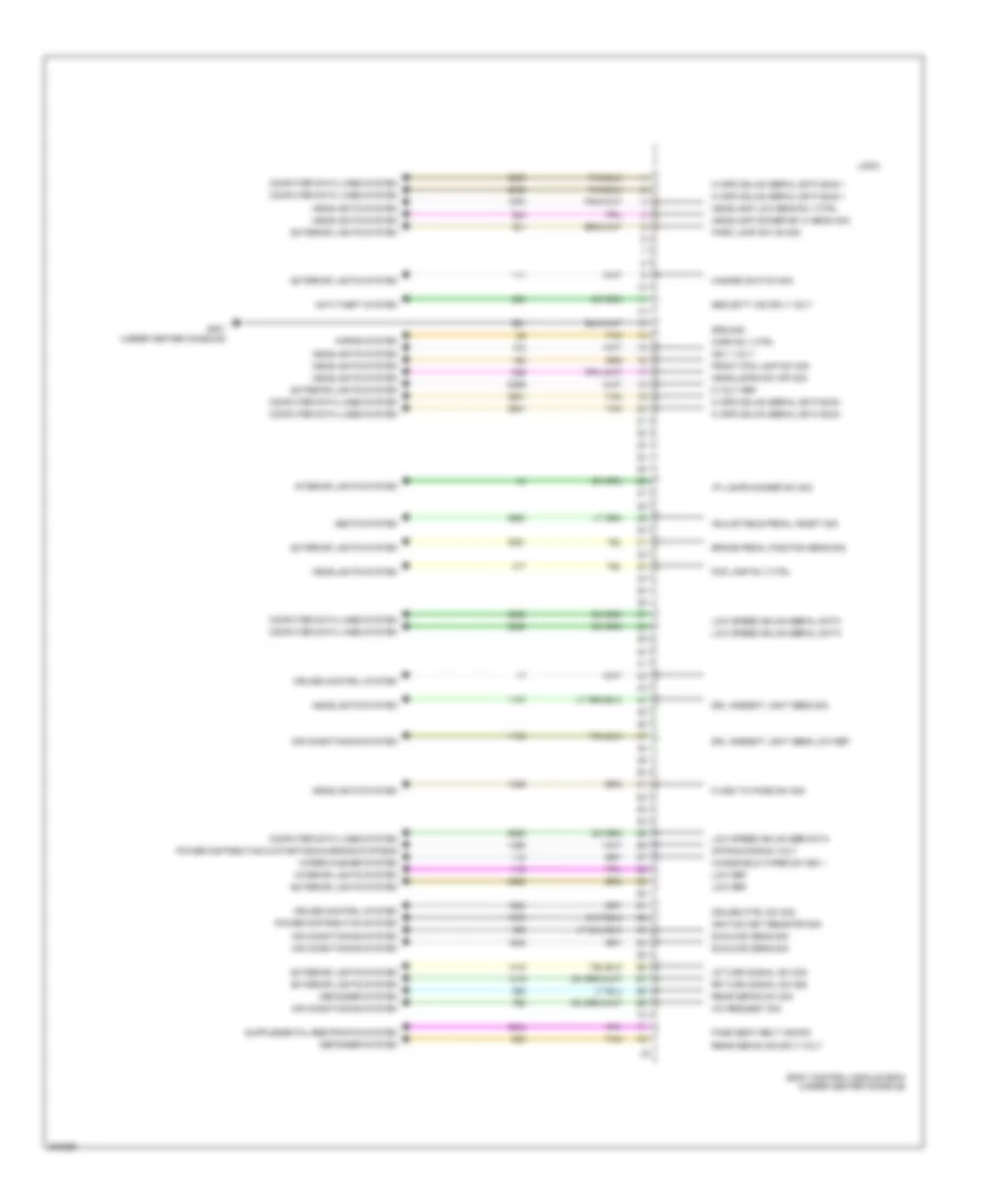
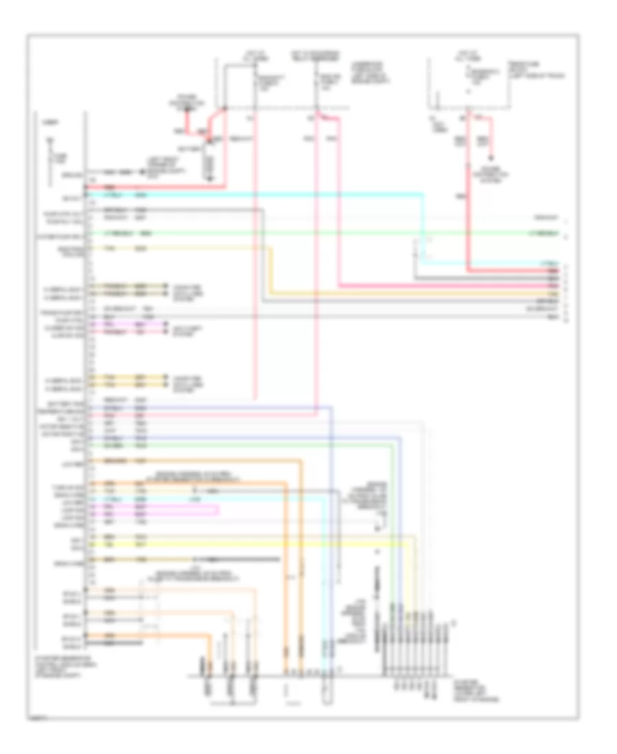
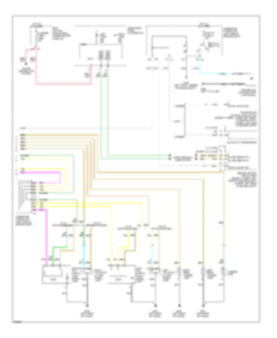
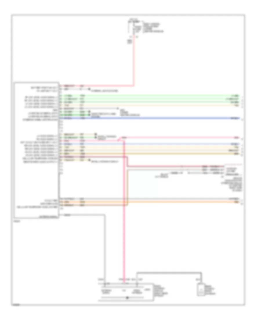
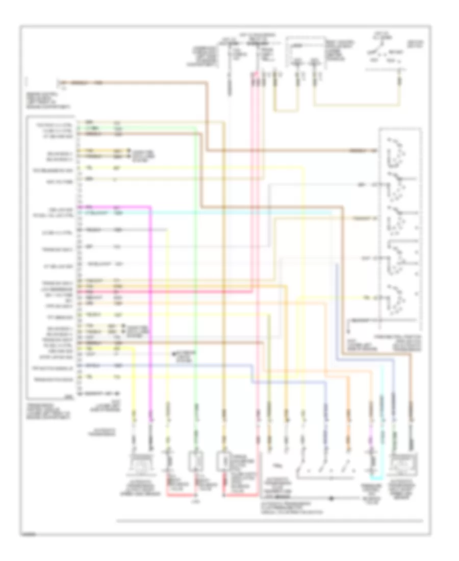
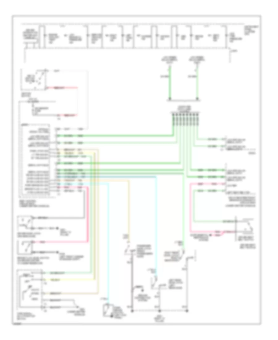
Automatic A/C Wiring Diagram (1 of 2) for Chevrolet Malibu LT 2009
 https://portal-diagnostov.com/license.html
Automotive Electricians Portal FZCO
Automotive Electricians Portal FZCO
https://portal-diagnostov.com/license.html
https://portal-diagnostov.com/license.html
Automotive Electricians Portal FZCO
Automotive Electricians Portal FZCO
List of elements for Automatic A/C Wiring Diagram (1 of 2) for Chevrolet Malibu LT 2009:
- (2.4l: left rear of engine) (3.6l: right front of engine) g106
- (355 mm from main breakout) (2.4l (vin 5)) j153
- (middle rear of engine) (2.4l (vin 5)) heater coolant pump
- 2.4l (vin b)
- 5 volt ref
- 87a
- A/c clu fuse 1 10a
- A/c clutch relay
- A/c compressor clutch (front of a/c compressor)
- A/c request ind
- A/c request switch
- A11
- Air temp dr pos sig
- Ambient air temperature sensor (center front of engine compt)
- Auto
- B10
- Bas pmps fuse 5 20a (2.4l (vin 5))
- Battery positive
- Blower motor switch
- Computer data lines system
- Cool fan 1 fuse 17 30a
- Cool fan 2 fuse 18 30a
- Cool/ fan 1 relay
- Cool/ fan 2 relay
- Cool/fan ser/par relay
- Defog ind
- Defog switch
- Door position sig
- Dr ctrl a
- Dr ctrl b
- Except 2.4l (vin b)
- Fresh air ind
- Fresh air switch
- G106 (2.4l: left rear of engine) (3.6l: right front of engine)
- G201 (under center console)
- Gnd
- High
- Hot at all times
- Hot w/ pwr/trn relay energized
- Hot w/ run/crank relay energized
- Hvac control module (center of dash)
- Ign 3 vol
- J151 (2.4l (vin 5)) (305 mm from main breakout) b
- Left engine cooling fan (behind left side of radiator)
- Left engine cooling fan diode (2.4l (vin 5)) (between left cooling fan & crankshaft position sensor)
- Logic
- Low
- Low ref
- Lower air temperature sensor (lower center of hvac module)
- Lower air temperature switch
- Mode dr ctrl
- Mode drv pos sig
- Mode switch
- Off
- Pnk
- Recir door ctrl
- Recirculation ind
- Recirculation switch
- Req sig
- Right engine cooling fan (behind right side of radiator)
- Right engine cooling fan diode (2.4l (vin 5)) (between right cooling fan & a/c compressor breakout)
- S152 (2.4l (vin 5))
- Sens signal
- Serial data
- Starter generator control module (sgcm) (left front of engine compt)
- Tan
- Underhood fuse block (left side of engine compt)
- Upper air temperature sensor (center of hvac module)
- Upper air temperature switch
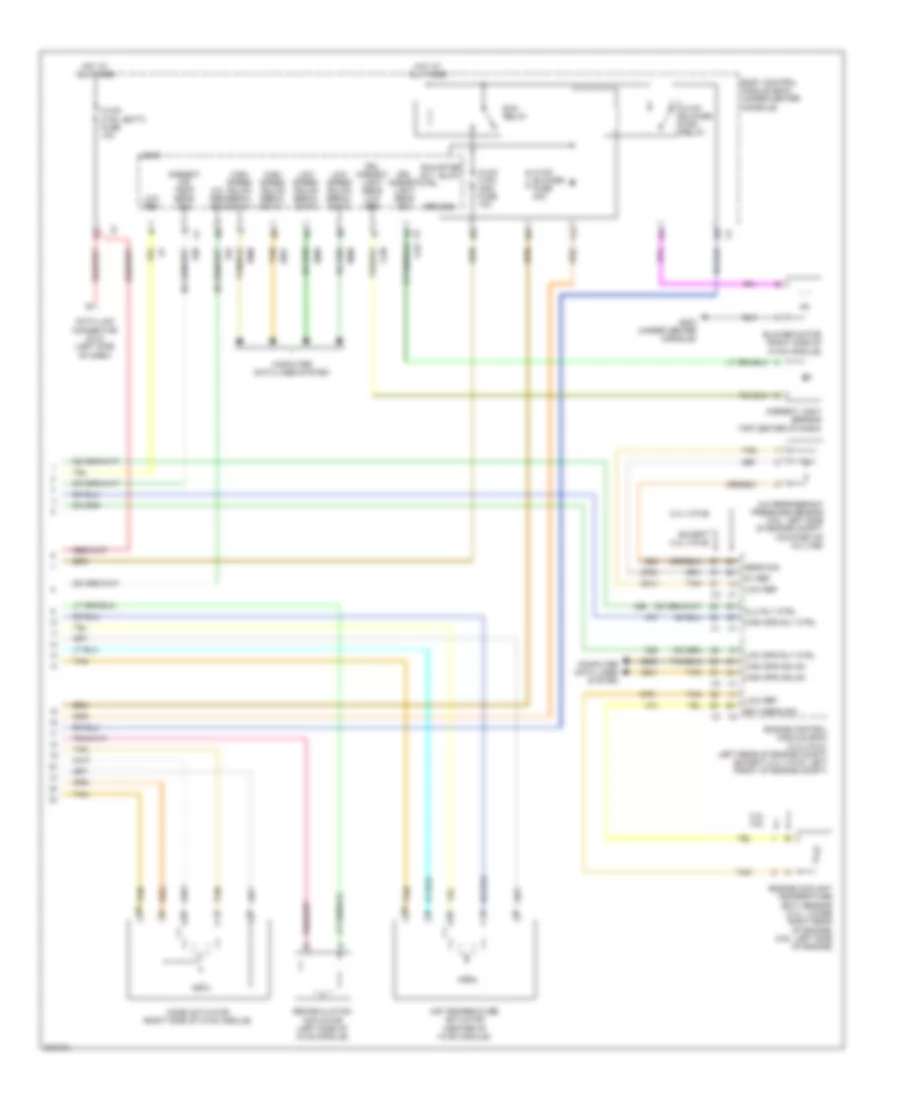
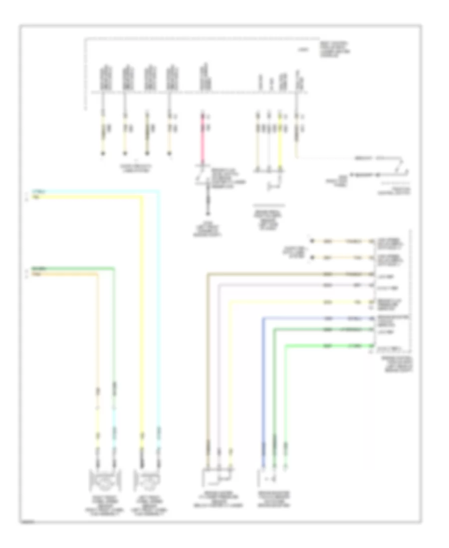
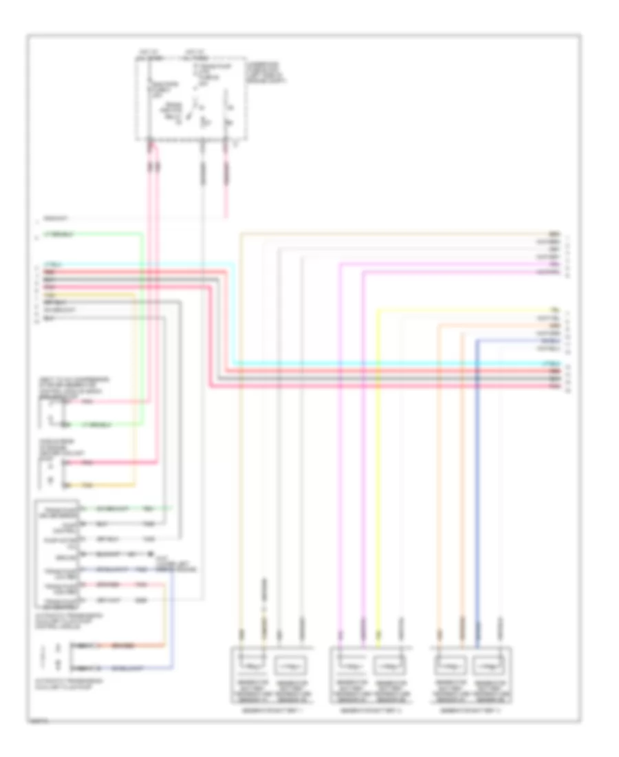
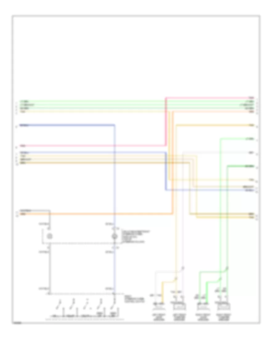
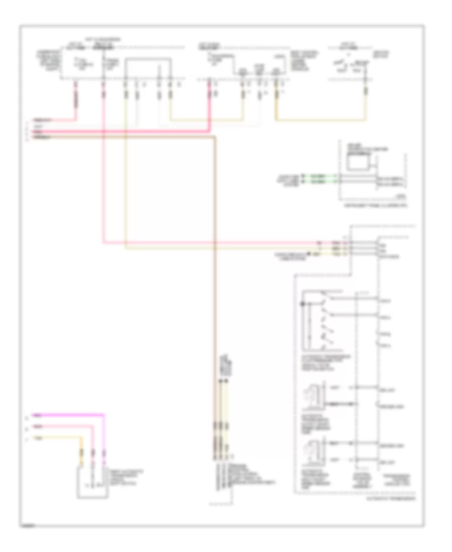
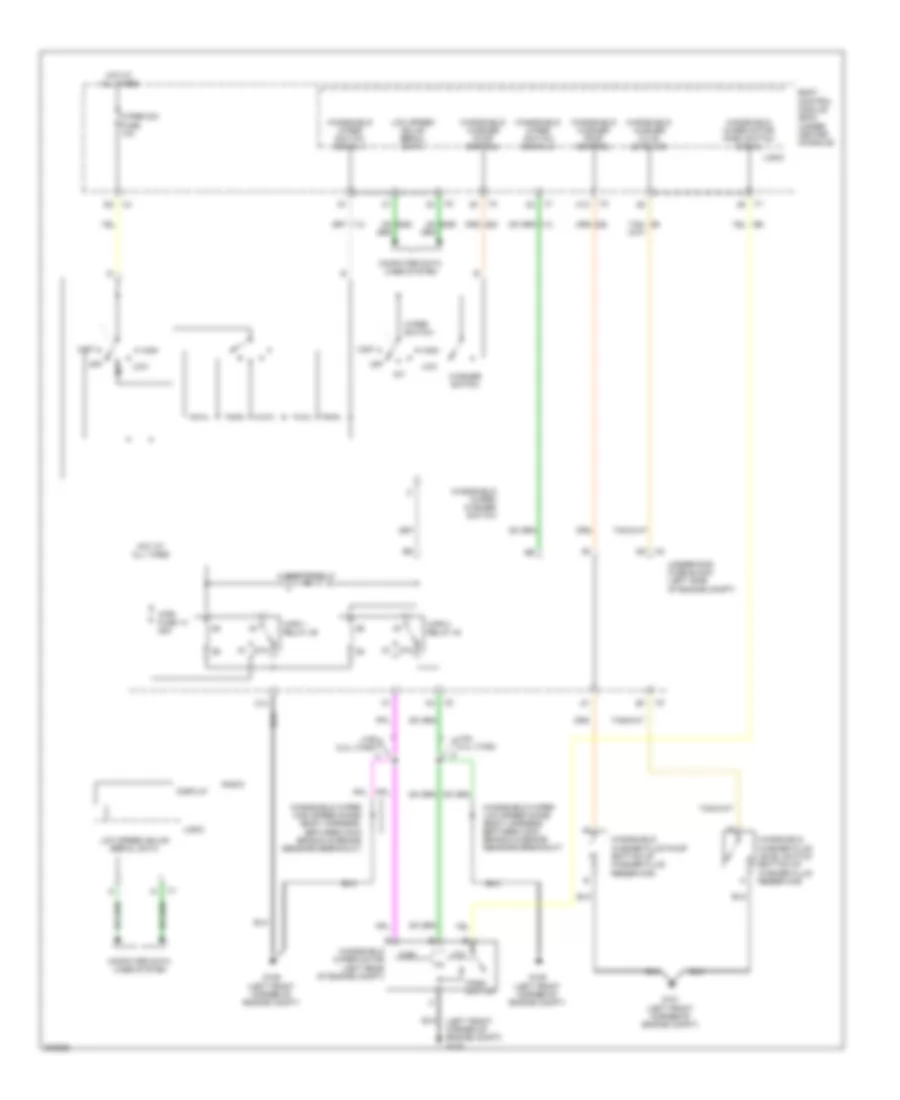
Automatic A/C Wiring Diagram (2 of 2) for Chevrolet Malibu LT 2009
List of elements for Automatic A/C Wiring Diagram (2 of 2) for Chevrolet Malibu LT 2009:
- (right side of hvac module) blower motor
- 2.4l (vin b)
- 2.4l 3.6l
- 5v ref
- A/c refrigerant pressure sensor (right rear of engine compt)
- Air temperature actuator (center of hvac module)
- Ambient air temp sens sig
- Battery positive
- Blower motor control module (rear of hvac case)
- Body control module (bcm) (under center console)
- Clu rly ctrl
- Computer data lines system
- Data link connector (dlc) (left side of dash)
- Drl ambient light sens low ref
- Drl ambient light sens sig
- Drv sunload sens sig
- Ect sens sig
- Engine control module (ecm) (2.4l(vin 5): left rear of engine compt) (except 2.4l(vin 5): left front of engine compt)
- Engine coolant temperature (ect) sensor (2.4l: lower right rear of engine) (3.6l: left side of engine)
- Except 2.4l (vin b)
- G203 (under center console)
- Gnd
- High spd gmlan data +
- High spd gmlan data -
- High spd rly ctrl
- High speed gmlan serial data +
- High speed gmlan serial data -
- Hot at all times
- Hvac ctrl (batt) fuse 10a
- Hvac ctrl (ign) fuse 10a
- Logic
- Low ref
- Low spd rly ctrl
- Low speed gmlan serial data
- Mode actuator (right side of hvac module)
- Recirculation actuator (left side of hvac module)
- Req sig
- Run relay
- Run rly ctrl
- Sens sig
- Spd ctrl
- Sply voltage
- Sunload sens sig
- Sunload sensor (center of dash)
- Tan
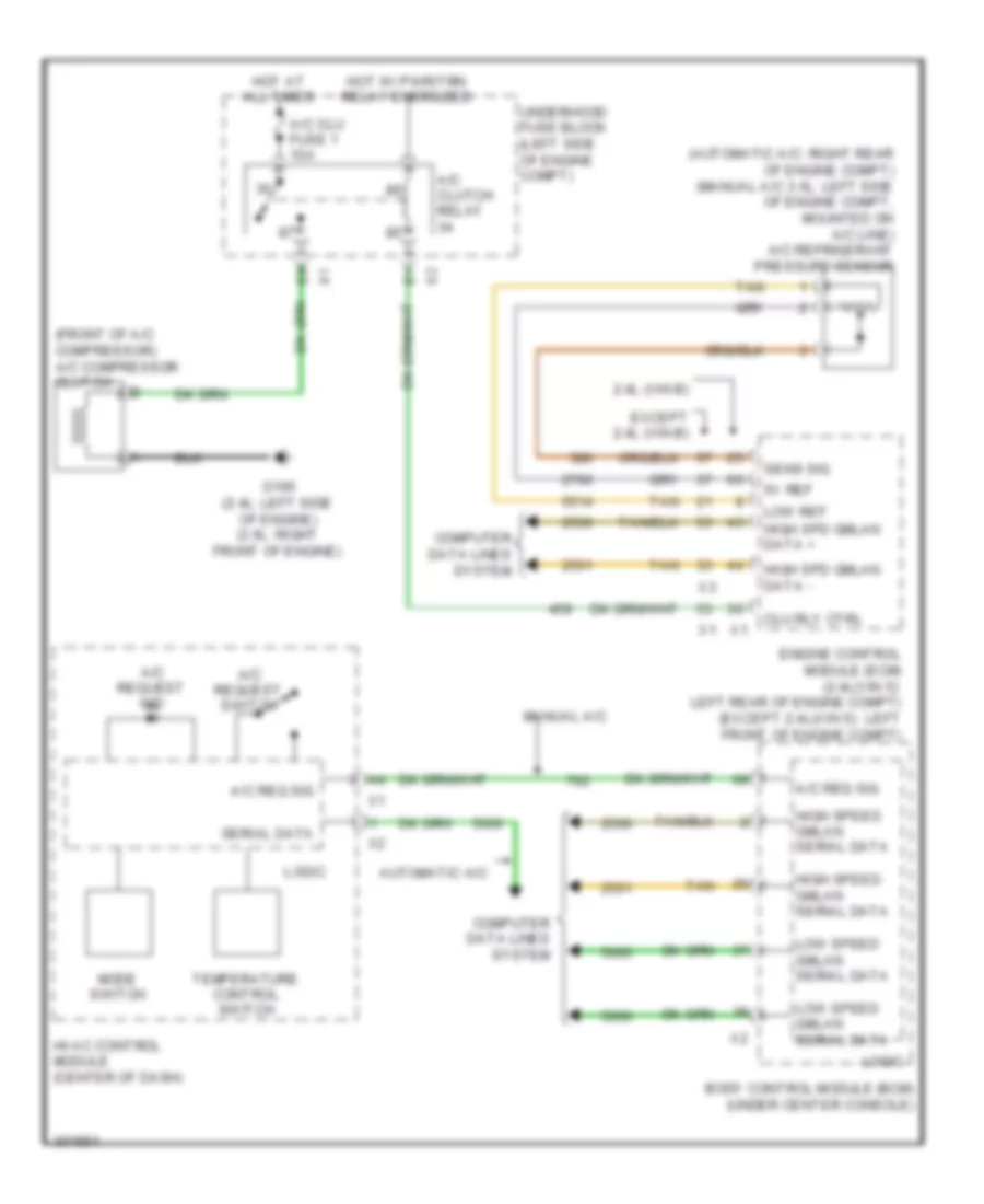
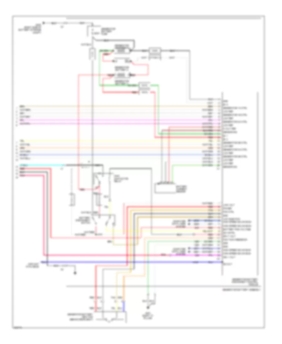
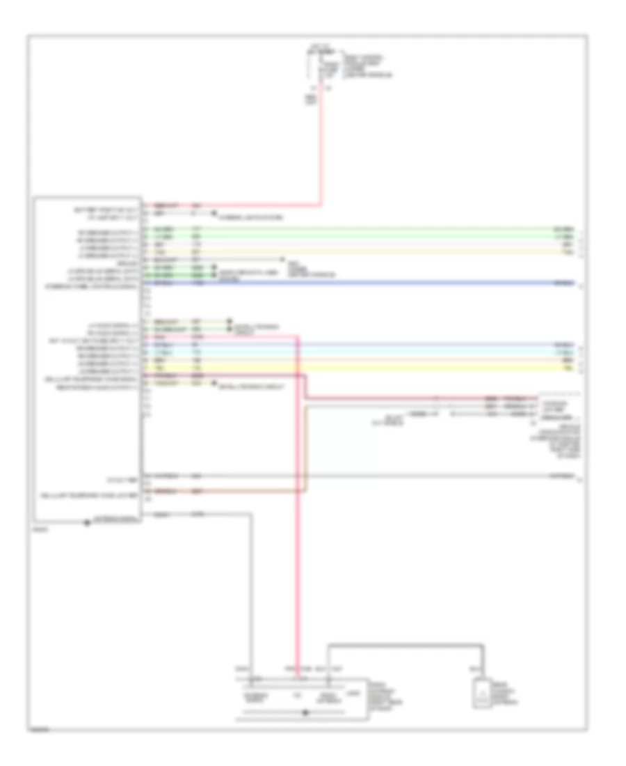
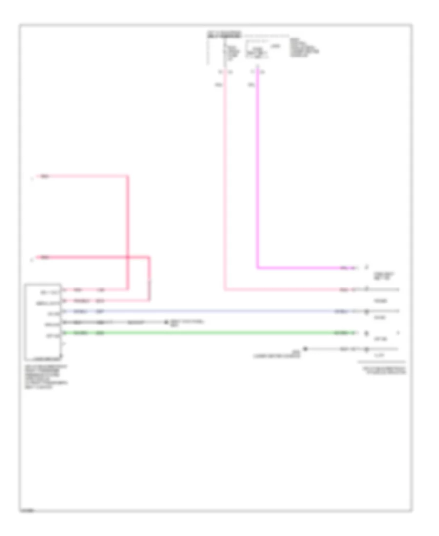
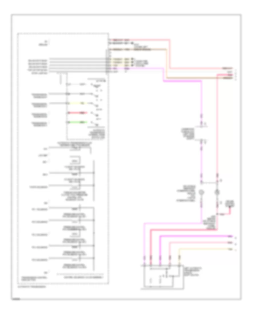
Compressor Wiring Diagram for Chevrolet Malibu LT 2009
List of elements for Compressor Wiring Diagram for Chevrolet Malibu LT 2009:
- (automatic a/c: right rear of engine compt) (manual a/c 3.6l: left side of engine compt, mounted on a/c line) a/c refrigerant pressure sensor
- (front of a/c compressor) a/c compressor clutch
- 2.4l (vin b)
- 5v ref
- A/c clu fuse 1 10a
- A/c clutch relay
- A/c req sig
- A/c request ind
- A/c request switch
- Automatic a/c
- Body control module (bcm) (under center console)
- Clu rly ctrl
- Computer data lines system
- Engine control module (ecm) (2.4l(vin 5): left rear of engine compt) (except 2.4l(vin 5):: left front of engine compt)
- Except 2.4l (vin b)
- G106 (2.4l: left side of engine) (3.6l: right front of engine)
- High spd gmlan data +
- High spd gmlan data -
- High speed gmlan serial data
- Hot at all times
- Hot w/ pwr/trn relay energized
- Hvac control module (center of dash)
- Logic
- Low ref
- Low speed gmlan serial data
- Manual a/c
- Mode switch
- Sens sig
- Serial data
- Tan
- Temperature control switch
- Underhood fuse block (left side of engine compt)
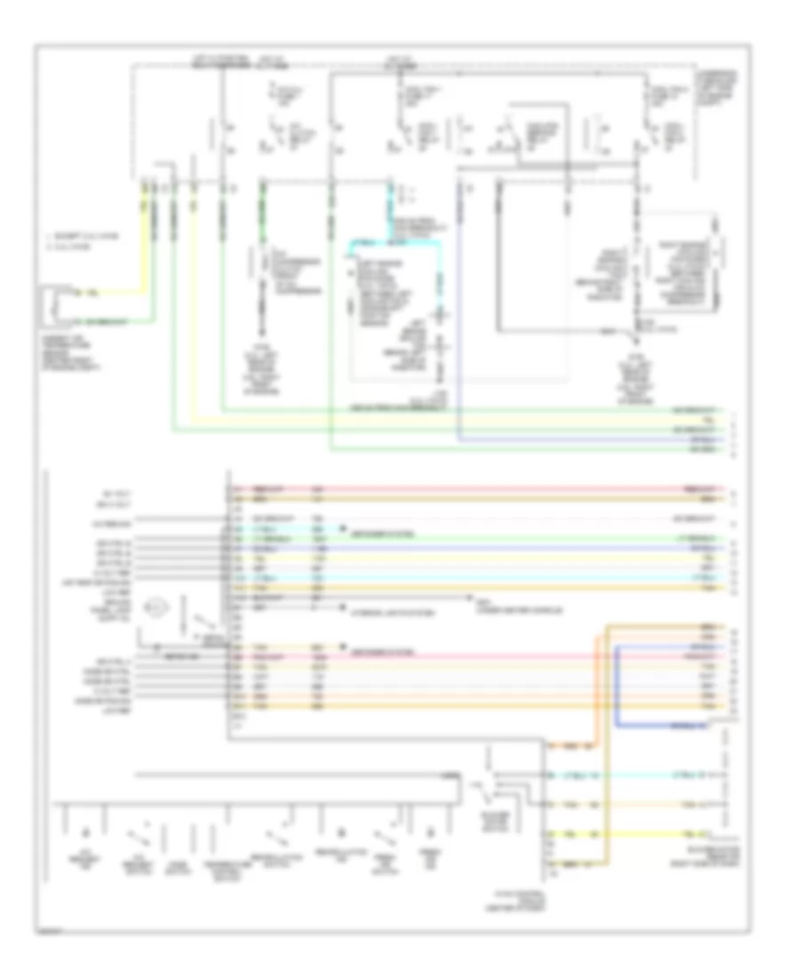
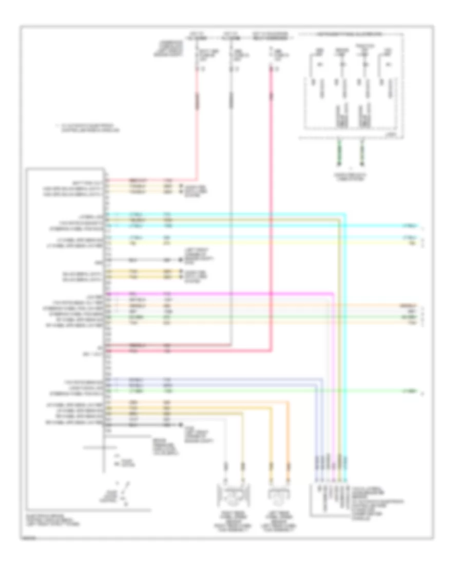
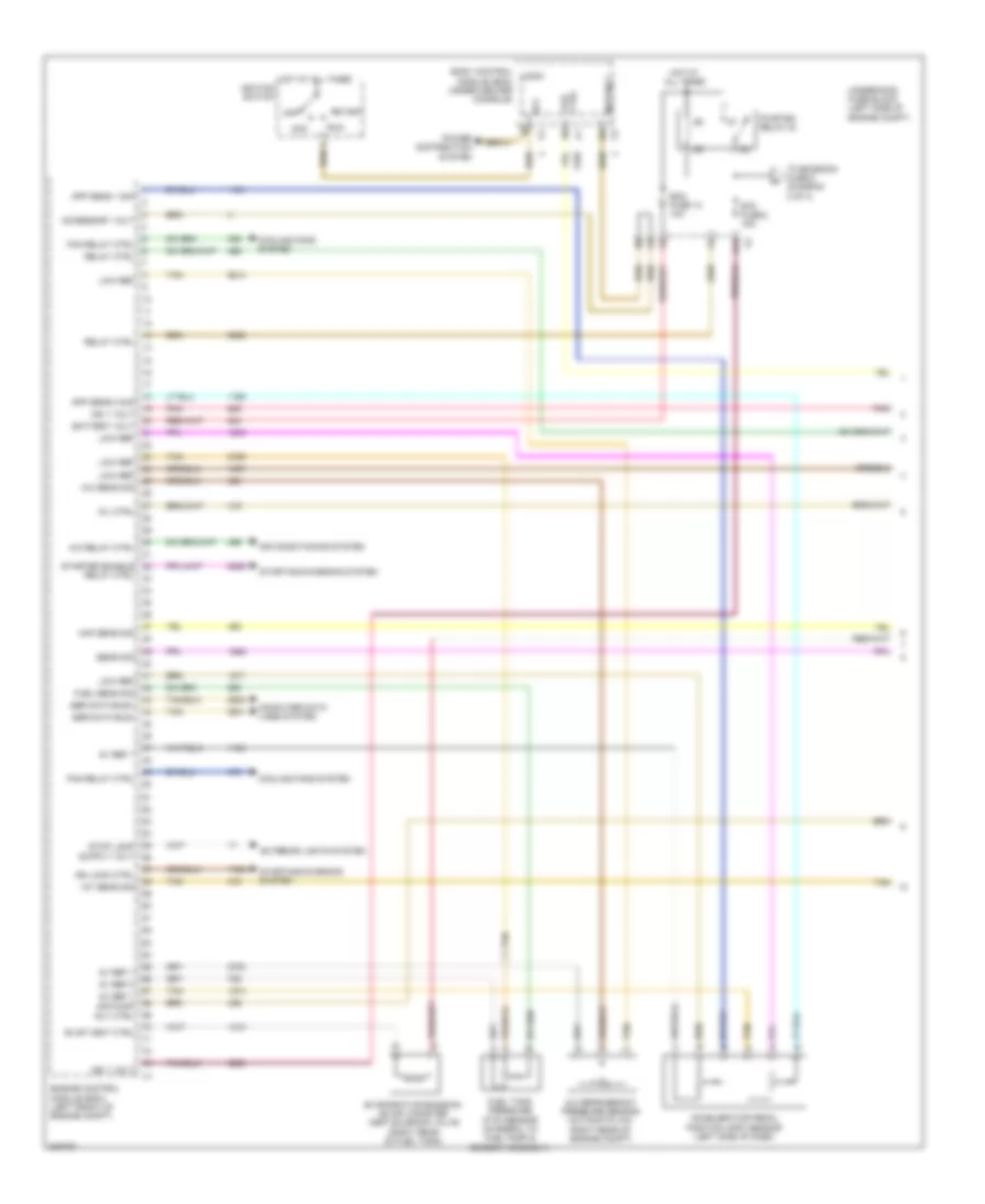
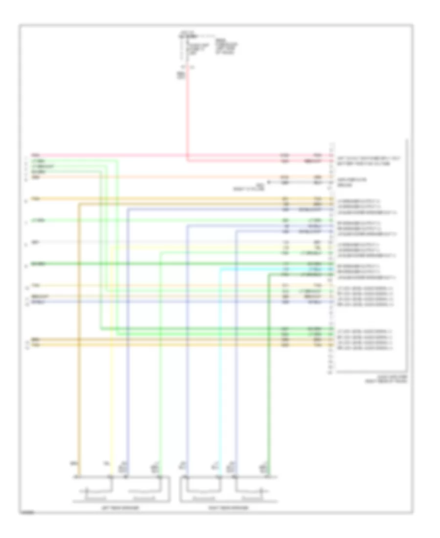
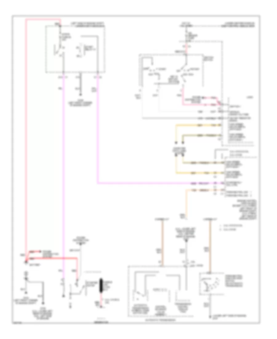
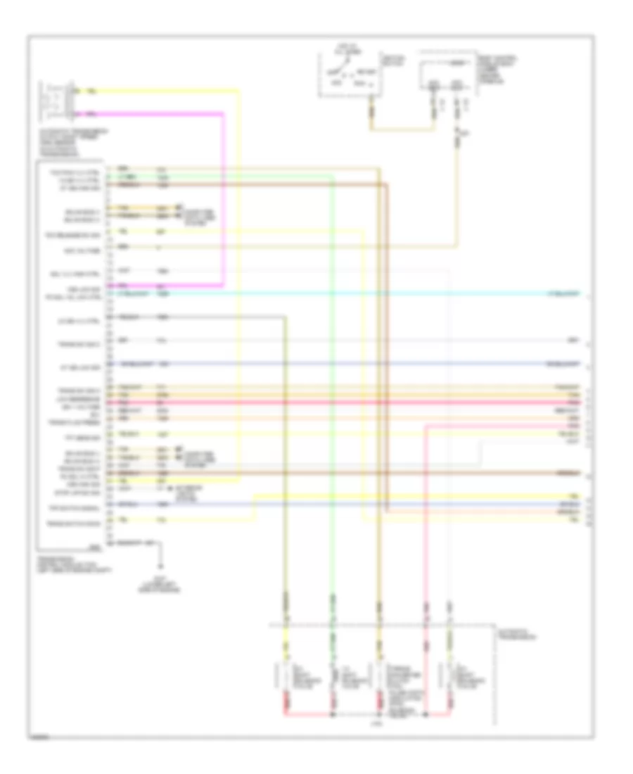
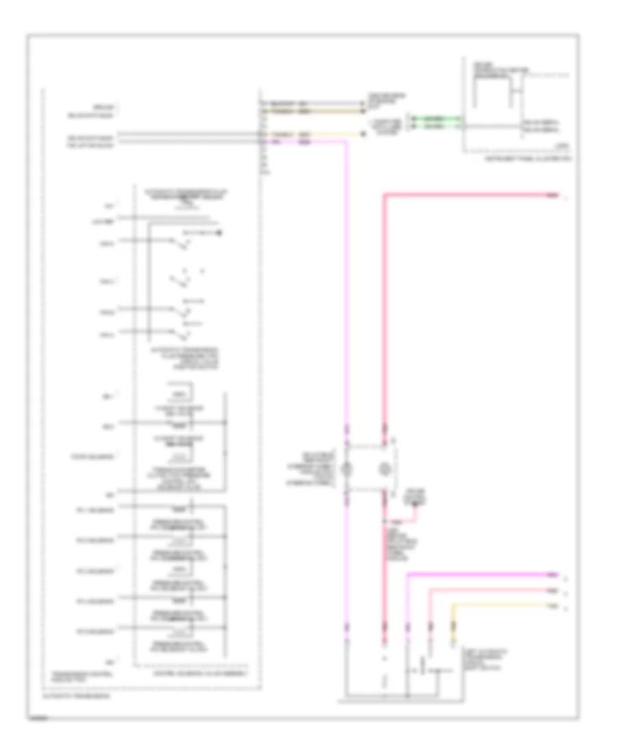
Manual A/C Wiring Diagram (1 of 2) for Chevrolet Malibu LT 2009
List of elements for Manual A/C Wiring Diagram (1 of 2) for Chevrolet Malibu LT 2009:
- (305 mm from main breakout) (2.4l (vin 5)) j151
- 2.4l (vin b)
- 5 volt ref
- 87a
- A/c clu fuse 1 10a
- A/c clutch relay
- A/c compressor clutch (front of a/c compressor)
- A/c req sig
- A/c request ind
- A/c request switch
- A10
- A11
- A12
- Air temp dr pos sig
- Ambient air temperature sensor (center front of engine compt)
- B+ volt
- B10
- B11
- B12
- Blower motor resistor (right side of dash)
- Blower motor switch
- Cool fan 1 fuse 17 30a
- Cool fan 2 fuse 18 30a
- Cool/ fan 1 relay
- Cool/ fan 2 relay
- Cool/fan ser/par relay
- Defog ind
- Defog switch
- Defogger system
- Dr ctrl a
- Dr ctrl b
- Except 2.4l (vin b)
- Fresh air ind
- Fresh air switch
- G106 (2.4l: left rear of engine) (3.6l: right front of engine)
- G201 (under center console)
- Ground
- Hot at all times
- Hot w/ pwr/trn relay energized
- Hvac control module (center of dash)
- Ign 3 volt
- Interior lights system
- J153 (2.4l (vin 5)) (355 mm from main breakout)
- Left engine cooling fan (behind left side of radiator)
- Left engine cooling fan diode (2.4l (vin 5)) (between left cooling fan & crankshaft position sensor)
- Logic
- Low ref
- Mode dr ctrl
- Mode dr pos sig
- Mode switch
- Panel lamp supp vol
- Recirculation ind
- Recirculation switch
- Right engine cooling fan (behind right side of radiator)
- Right engine cooling fan diode (2.4l (vin 5)) (between right cooling fan & a/c compressor breakout)
- Tan
- Temperature control switch
- Underhood fuse block (left side of engine compt)
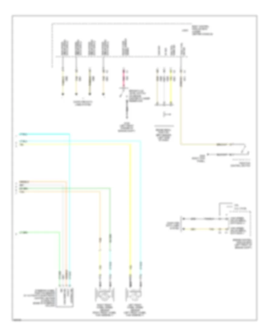
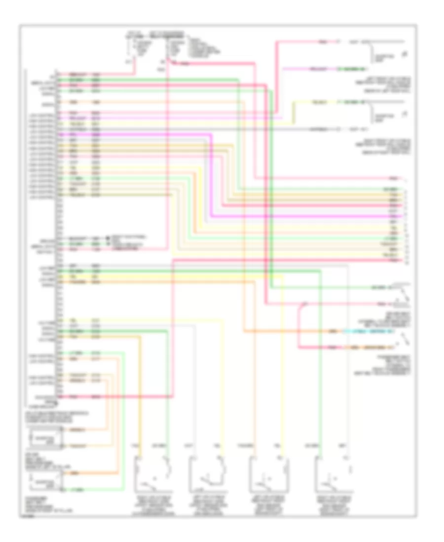
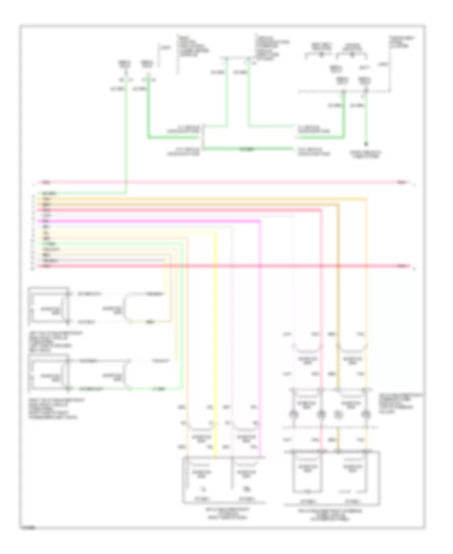
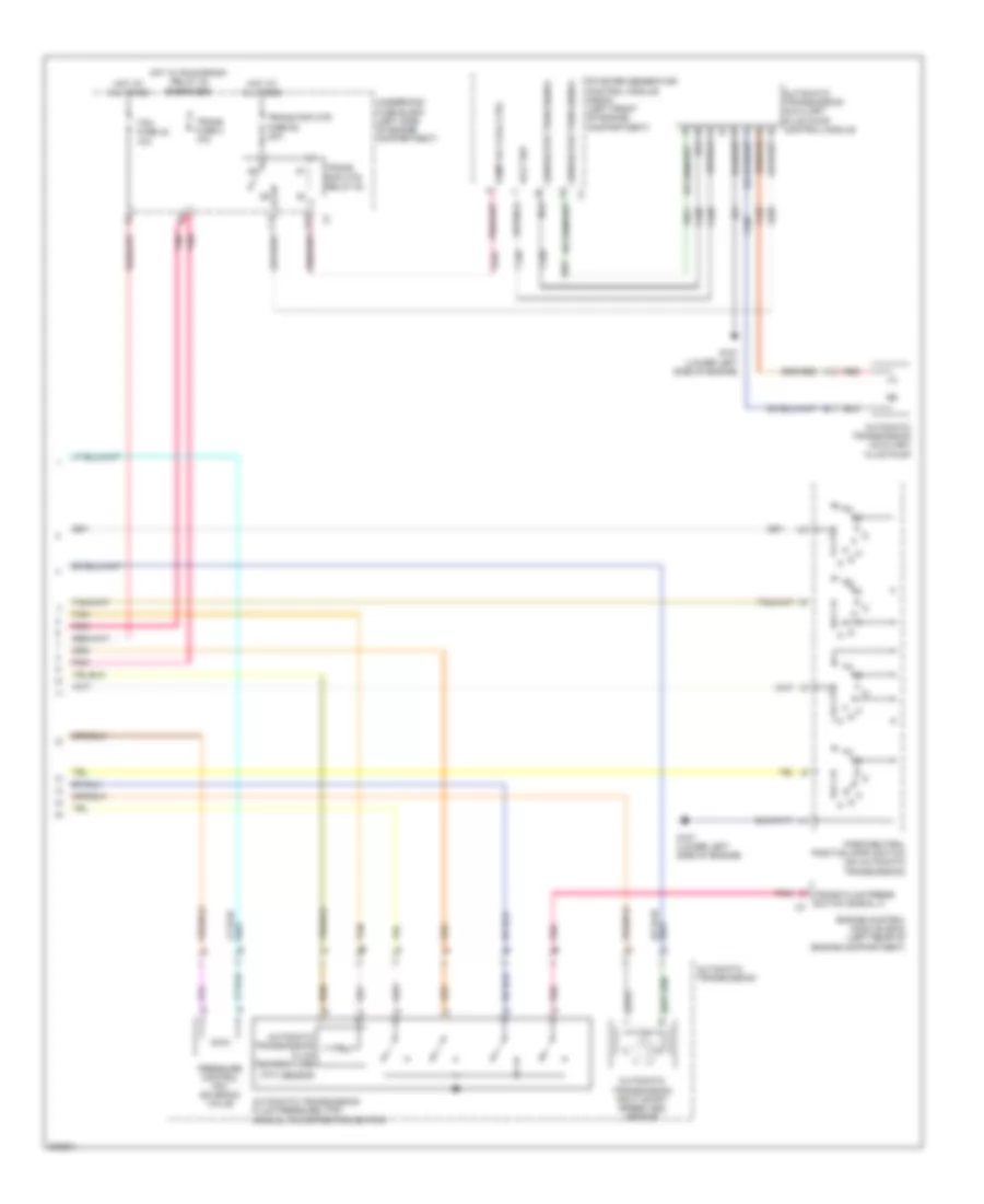
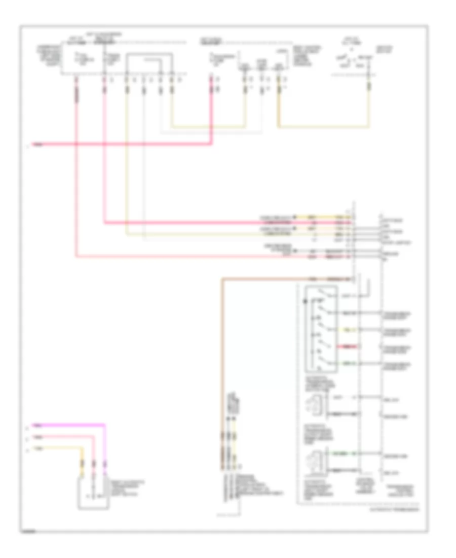
Manual A/C Wiring Diagram (2 of 2) for Chevrolet Malibu LT 2009
List of elements for Manual A/C Wiring Diagram (2 of 2) for Chevrolet Malibu LT 2009:
- 2.4l (vin b)
- 2.4l 3.6l
- 5v ref
- A/c refrigerant pressure sensor (3.6l: left side of engine compt, mounted on a/c line)
- A/c req sig
- After blow
- Air temperature actuator (center of hvac module)
- Ambient air temp sens sig
- Ambient light sensor (top center of dash)
- Blower motor (right side of hvac module)
- Body control module (bcm) (under center console)
- Clu rly ctrl
- Computer data lines system
- Data link connector (dlc) (left side of dash)
- Drl ambient light sens low ref
- Drl ambient light sens sig
- Ect sens sig
- Engine control module (ecm) (2.4l(vin 5): left rear of engine compt) (except 2.4l (vin 5): left front of engine compt)
- Engine coolant temperature (ect) sensor (2.4l: lower right rear of engine) (3.6l: left side of engine)
- Except 2.4l (vin b)
- G203 (under center console)
- Ground
- High spd gmlan
- High spd rly ctrl
- High speed gmlan serial data +
- High speed gmlan serial data -
- Hot at all times
- Hvac blower fuse 20a
- Hvac blower high relay
- Hvac ctrl (batt) fuse 10a
- Hvac ctrl (ign) fuse 10a
- Logic
- Low ref
- Low spd rly ctrl
- Low speed gmlan serial data
- Mode actuator (right side of hvac module)
- Recirculation actuator (left side of hvac module)
- Run relay
- Run rly ctrl
- Sens sig
- Tan
ANTI-LOCK BRAKES
Anti-lock Brakes Wiring Diagram, Except Hybrid (1 of 2) for Chevrolet Malibu LT 2009
List of elements for Anti-lock Brakes Wiring Diagram, Except Hybrid (1 of 2) for Chevrolet Malibu LT 2009:
- (left front corner of engine compt) g109
- 5-volt
- Abs fuse 15 10a
- Abs fuse 24 60a
- Abs ind
- Batt abs fuse 56 30a
- Batt pos volt
- Brake ind
- Brake pressure modulator valve (bpmv)
- Computer data lines system
- Diagnostic
- Electronic brake control module (ebcm) (left front strut tower)
- G109 (left front corner of engine compt)
- Gmlan serial data -
- Gnd
- High spd gmlan serial data +
- Hot at all times
- Hot w/ run/crank relay energized
- Ign
- Ign 1 volt
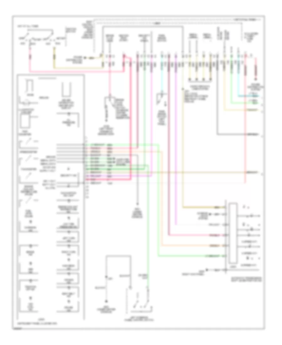
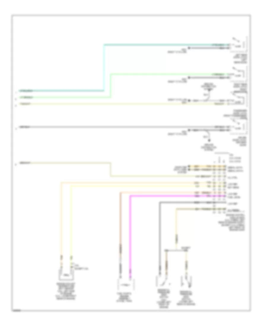
- Instrument panel cluster (ipc)
- Lateral sig
- Left rear wheel speed sensor (left rear wheel hub assembly)
- Lf wheel spd sens low ref
- Lf wheel spd sens sig
- Logic
- Longitudinal sig
- Low ref
- Low speed
- Low speed gmlan serial data
- Lr wheel spd sens low ref
- Lr wheel spd sens sig
- Pnk
- Pump motor
- Pump motor control
- Rf wheel spd sens low ref
- Rf wheel spd sens sig
- Right rear wheel speed sensor (right rear wheel hub assembly)
- Rr wheel spd sens low ref
- Rr wheel spd sens sig
- Ser data
- Serial data gmlan
- Sig
- Steering wheel pos low ref
- Steering wheel pos sens
- Steering wheel pos sig a
- Steering wheel pos sig b
- Tan
- Traction off ind
- Underhood fuse block (left side of engine compt)
- Vdc ind
- W/ automatic electronic controlled ride & handling
- Yaw & lateral accelerometer sensor (w/ automatic electronic controlled ride & handling) (under center console)
- Yaw rate diagnostic
- Yaw rate sens sig
- Yaw rate sens volt ref
- Yaw sens sig
Anti-lock Brakes Wiring Diagram, Except Hybrid (2 of 2) for Chevrolet Malibu LT 2009
List of elements for Anti-lock Brakes Wiring Diagram, Except Hybrid (2 of 2) for Chevrolet Malibu LT 2009:
- 2.4l (vin b)
- 3.6l
- 5-volt
- 5v ref
- Body control module (bcm) (under center console)
- Brake fluid level sensor
- Brake fluid level switch (on brake master cylinder reservoir)
- Brake pedal position (bpp) sensor (left side of dash)
- Brk pos sens sig
- Computer data lines system
- Data bus (+) gmlan serial high speed
- Data bus (-) gmlan serial high speed
- Engine control module (ecm) (left front of engine compt)
- G109 (left front corner of engine compt)
- G305 (right kick panel)
- Gmlan serial data bus (+)
- High speed
- High speed gmlan serial data bus (+)
- High speed gmlan serial data bus (-)
- Lateral sig
- Left front wheel speed sensor (left front wheel hub assembly)
- Logic
- Low ref
- Nca
- Pnk
- Right front wheel speed sensor (right front wheel hub assembly)
- Sig
- Signal
- Steering wheel position sensor (w/ automatic electronic controlled ride & handling) (base of steering column)
- Tan
- Trac ctrl sw sig
- Traction control switch
- Yaw sens sig
Anti-lock Brakes Wiring Diagram, Hybrid (1 of 2) for Chevrolet Malibu LT 2009
List of elements for Anti-lock Brakes Wiring Diagram, Hybrid (1 of 2) for Chevrolet Malibu LT 2009:
- (not used)
- 5-volt
- Abs fuse 15 10a
- Abs fuse 24 60a
- Abs ind
- Bat
- Brake ind
- Brake pressure modulator valve (bpmv)
- Computer data lines system
- Electronic brake control module (ebcm) (left front strut tower)
- G109 (left front corner of engine compt)
- Gmlan serial data (+)
- Gmlan serial data (-)
- Ground
- Hot at all times
- Hot w/ run/crank relay energized
- Ign
- Ign 1 voltage
- Instrument panel cluster (ipc)
- Lateral accelerometer sig
- Left rear wheel speed sensor (left rear wheel hub assembly)
- Lf wheel sens sply voltage
- Lf wheel spd sens sig
- Logic
- Low ref
- Low speed
- Low speed gmlan serial data
- Lr wheel sens sply voltage
- Lr wheel spd sens low ref
- Pnk
- Pump motor
- Pump motor control
- Rf wheel sens sply voltage
- Rf wheel spd sens sig
- Right rear wheel speed sensor (right rear wheel hub assembly)
- Rr wheel sens sply voltage
- Rr wheel spd sens sig
- Ser data
- Serial data gmlan
- Sig
- Tan
- Traction off ind
- Underhood fuse block (left side of engine compt)
- Vdc ind
- Yaw & lateral accelerometer sensor (under center console)
- Yaw rate sens sig
- Yaw sens
Anti-lock Brakes Wiring Diagram, Hybrid (2 of 2) for Chevrolet Malibu LT 2009
List of elements for Anti-lock Brakes Wiring Diagram, Hybrid (2 of 2) for Chevrolet Malibu LT 2009:
- 5-volt ref
- 5-volt ref 2
- 5v ref
- Body control module (bcm) (under center console)
- Brake booster vacuum sens sig
- Brake booster vacuum sensor (on power brake booster)
- Brake fluid
- Brake fluid level switch (on brake master cylinder reservoir)
- Brake fluid pressure sens sig
- Brake master cylinder pressure sensor (below master cylinder)
- Brake pedal position (bpp) sensor (left side of dash)
- Computer data lines system
- Data bus (+)
- Data bus (-) gmlan serial
- Engine control module (ecm) (left rear of engine compt)
- G109 (left front corner of engine compt)
- G305 (right kick panel)
- Gmlan serial data bus (+)
- High speed
- High speed gmlan serial
- High speed gmlan serial data bus (+)
- High speed gmlan serial data bus (-)
- Left front wheel speed sensor (left front wheel hub assembly)
- Level sensor signal
- Logic
- Low ref
- Nca
- Pnk
- Right front wheel speed sensor (right front wheel hub assembly)
- Sens sig brk pos
- Sw sig trac ctrl
- Tan
- Traction control switch
ANTI-THEFT
Anti-theft Wiring Diagram for Chevrolet Malibu LT 2009
List of elements for Anti-theft Wiring Diagram for Chevrolet Malibu LT 2009:
- (center of dash) hvac control module
- (left front of engine compt) starter generator control module (sgcm)
- 2.4l (vin 5)
- Acc
- Acc volt
- Ajar
- Automatic a/c
- B10
- Battery
- Body control module (bcm) (under center console)
- Closed
- Cluster/ theft fuse 10a
- Computer data lines system
- Ctrl
- Data bus+
- Data bus-
- Door lock fuse 15a
- Dr lk lk/ unlk sig
- Driver door door latch (driver's door)
- Driver door lock switch
- Except 2.4l (vin 5)
- Exterior lights system
- G101 (left front corner of engine compt)
- G201 (under center console)
- G301 (right "c" pillar)
- Ground
- Hdlp hi beam rly
- Headlights system
- Hood ajar switch (on hood latch)
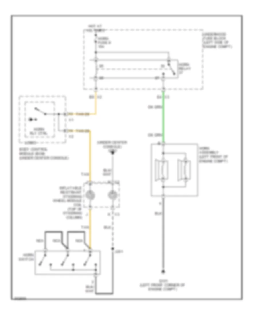
- Horns system
- Hot at all times
- Ign key resistor sig
- Ignition switch
- Instrument panel cluster (ipc)
- Interior lights system
- Key in ignition switch
- Key sw sig
- Left rear door latch (left rear door)
- Lf dr ajar sw sig dr ajar sw sig
- Lock
- Logic
- Low spd gmlan
- Low spd serial
- Manual a/c
- Off
- Off/run/ crank volt
- Passenger door latch (front passenger's door)
- Passenger door lock switch
- Power distribution system
- Radio
- Right rear door latch (right rear door)
- Rly ctrl park lamp
- Run
- Security ind
- Serial data
- Start
- Sw sig
- Sw sig horn rly ctrl
- Tan
- Theft deterrent module (tdm) (on ignition key cylinder housing)
- Trunk, tailgate, fuel doors system
- Underhood fuse block (left side of engine compt)
- Unlock
- Vehicle communications interface module (vcim) (right side of dash)
- W/ onstar
- W/o onstar
BODY CONTROL MODULES
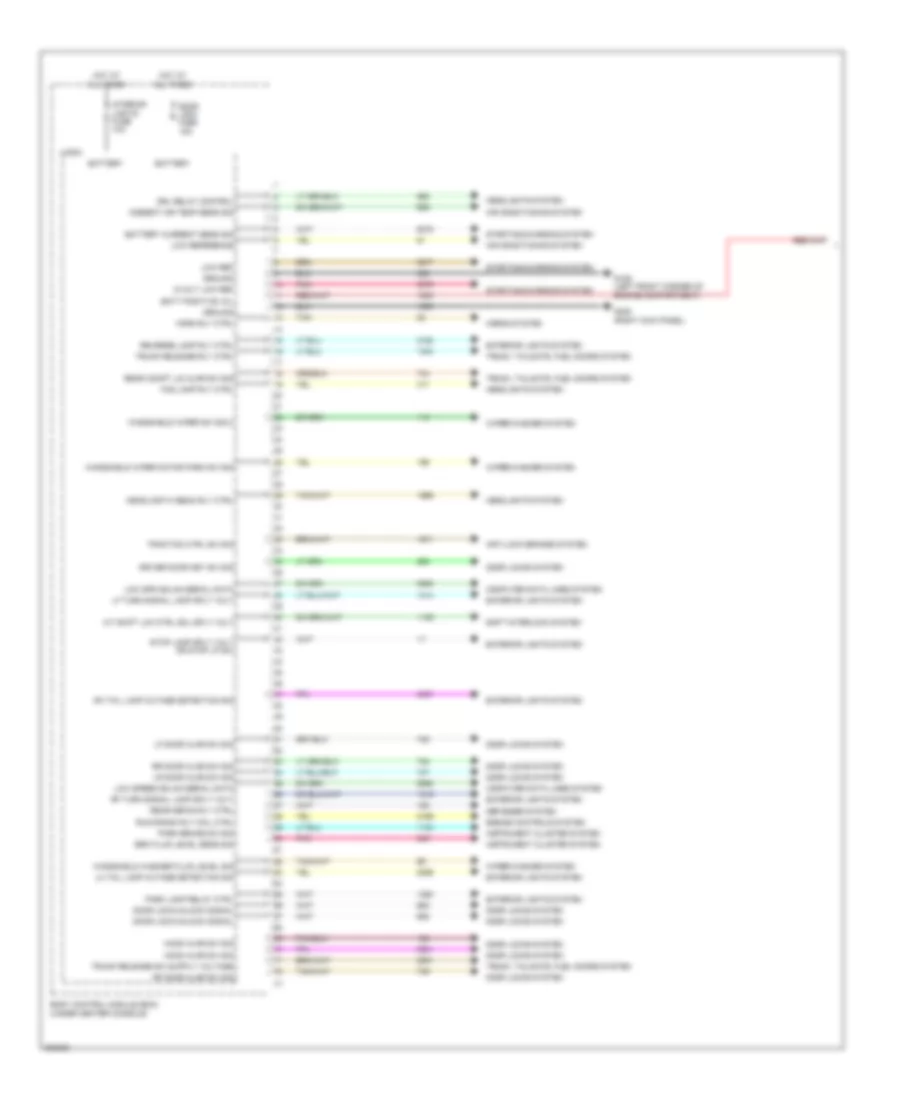
Body Control Modules Wiring Diagram (1 of 4) for Chevrolet Malibu LT 2009
List of elements for Body Control Modules Wiring Diagram (1 of 4) for Chevrolet Malibu LT 2009:
- 5-volt low ref
- A/t shift lck ctrl sol sply volt
- Air conditioning system
- Ambient air temp sens sig
- Anti-lock brakes system
- Batt positive vol
- Battery
- Battery current sens sig
- Body control module (bcm) (under center console)
- Brk fluid level sens sig
- Computer data lines system
- Defogger system
- Door lock fuse 15a
- Door lock/unlock signal
- Door locks system
- Driver door key sw sig
- Drl relay control
- Engine controls system
- Exterior lights system
- Fog lamp rly ctrl
- G109 (left front corner of engine compartment)
- G305 (right kick panel)
- Ground
- Headlamp hi beam rly ctrl
- Headlights system
- Hood ajar sw sig
- Horn rly ctrl
- Horns system
- Hot at all times
- Instrument cluster system
- Interior lights fuse 10a
- Lf door ajar sw sig
- Lf turn signal lamp sply volt
- Lh tail lamp outage detection sig
- Logic
- Low ref
- Low reference
- Low spd gmlan serial data
- Low speed gmlan serial data
- Lr door ajar sw sig
- Park brake sw sig
- Park lamp relay ctrl
- Pnk
- Rear compt lid ajar sw sig
- Rear defog rly ctrl
- Reverse lamp rly ctrl
- Rf door ajar sw sig
- Rf turn signal lamp sply volt
- Rh tail lamp outage detection sig
- Rr door ajar sw sig
- Run/crank rly coil ctrl
- Shift interlock system
- Starting/charging system
- Stop lamp sply volt or stop lp sw
- Tan
- Traction ctrl sw sig
- Trunk release rly ctrl
- Trunk, tailgate, fuel doors system
- Windshield washer fluid level sig
- Windshield wiper motor park sw sig
- Windshield wiper sw sig 2
- Wiper/washer system
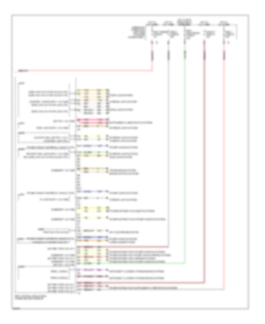
Body Control Modules Wiring Diagram (2 of 4) for Chevrolet Malibu LT 2009
List of elements for Body Control Modules Wiring Diagram (2 of 4) for Chevrolet Malibu LT 2009:
- A10
- A11
- A12
- Accessory voltage
- Anti-lock brakes system
- B10
- B11
- B12
- Batt sense fuse 54 5a
- Battery positive volt
- Body control module (bcm) (under center console)
- C10
- C11
- C12
- Courtesy lamp ctrl
- D10
- D11
- D12
- Door lock actuator lock ctrl
- Door lock actuator unlock ctrl
- Door locks system
- Drv door lock actuator unlock ctrl
- Engine controls system
- Exterior lights system
- Hot at all times
- Hot w/ run/ crank relay energized
- Ibcm (run/crank) fuse 21 30a
- Ibcm 1 fuse 20 30a
- Ibcm 2 fuse 25 50a
- Ignition 1 voltage
- Instrument cluster & transmissions systems
- Interior lights system
- Logic
- Lr stop/turn lamp sply volt
- Pnk
- Power distribution & mirrors systems
- Power distribution & power windows systems
- Power distribution & seats systems
- Power distribution, power tops & mirrors systems
- Power window master sw lockout ctrl
- Power windows system
- Prndl a signal
- Prndl b signal
- Run rly fuse 19 30a
- Tan
- Traction ctrl sw sig
- Transmissions system
- Underhood fuse block (left side of engine compartment)
- Windshield washer pump ctrl
- Wiper/washer system
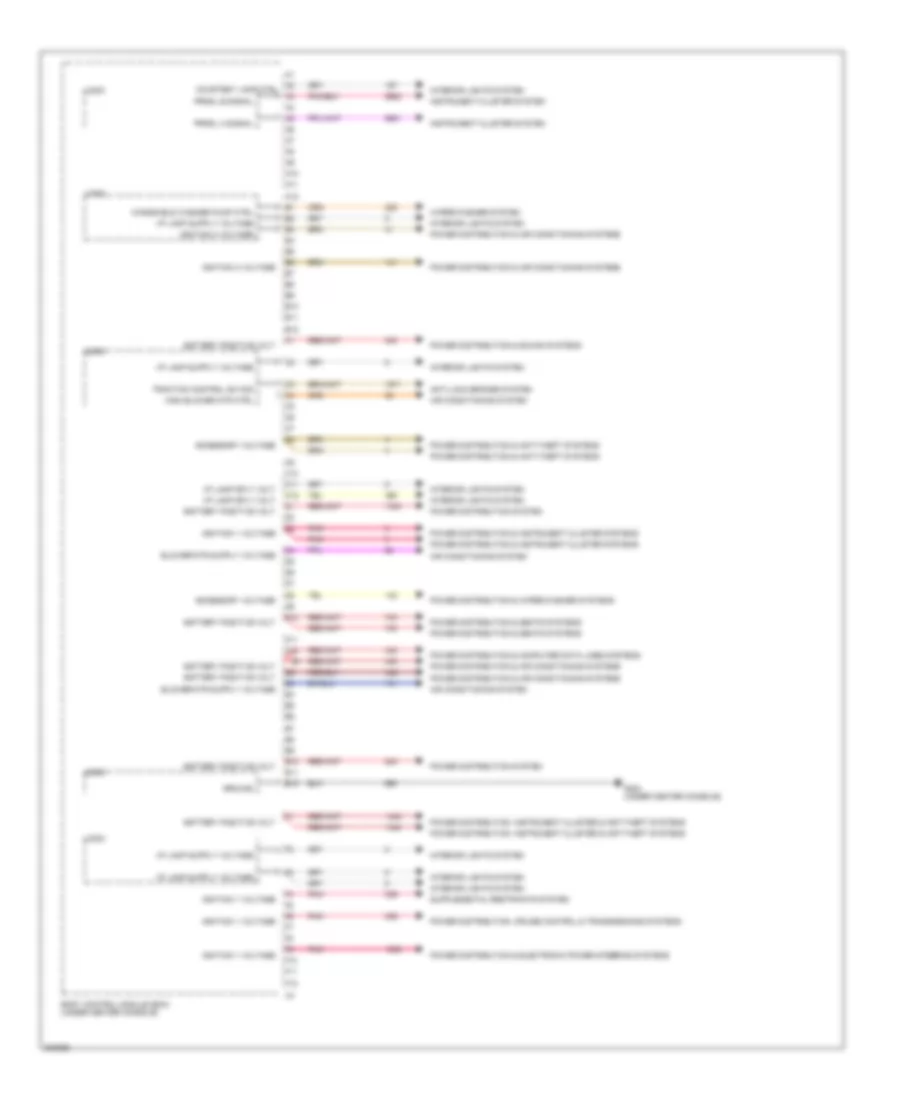
Body Control Modules Wiring Diagram (3 of 4) for Chevrolet Malibu LT 2009
List of elements for Body Control Modules Wiring Diagram (3 of 4) for Chevrolet Malibu LT 2009:
- A10
- A11
- A12
- A2 courtesy lamp ctrl
- Accessory voltage
- Air conditioning system
- Anti-lock brakes system
- B10
- B11
- B12
- Battery positive volt
- Body control module (bcm) (under center console)
- C10
- C11
- C12
- D10
- D11
- D12
- E10
- E11
- E12
- F10
- F11
- F12
- G203 (under center console)
- Ground
- High blower mtr ctrl
- I/p lamp sply volt
- Ignition 1 voltage
- Ignition 3 voltage
- Instrument cluster system
- Interior lights system
- Logic
- Pnk
- Power distribution & air conditioning systems
- Power distribution & anti-theft systems
- Power distribution & computer data lines systems
- Power distribution & electronic power steering systems
- Power distribution & instrument cluster systems
- Power distribution & seats systems
- Power distribution & sound systems
- Power distribution & wiper/washer systems
- Power distribution system
- Power distribution, cruise control & transmissions systems
- Power distribution, instrument cluster & anti-theft systems
- Prndl a signal
- Prndl b signal
- Traction control sw sig
- Windshield washer pump ctrl
- Wiper/washer system
Body Control Modules Wiring Diagram (4 of 4) for Chevrolet Malibu LT 2009
List of elements for Body Control Modules Wiring Diagram (4 of 4) for Chevrolet Malibu LT 2009:
- 5 volt ref
- A/c request sig
- Adjustable pedal inhibit sig
- Air conditioning system
- Anti-theft system
- Body control module (bcm) (under center console)
- Brake pedal position sens sig
- Computer data lines system
- Cruise control system
- Cruise ctrl sw sig
- Defogger system
- Drl ambient light sens low ref
- Drl ambient light sens sig
- Exterior lights system
- Flash to pass sw sig
- Fog lamp rly ctrl
- Front fog lamp sw sig
- G201 (under center console)
- Ground
- Hazard switch sig
- Headlamp dimmer sw hi beam sig
- Headlamp low beam rly ctrl
- Headlamps sw off sig
- Headlights system
- Hi spd gmlan serial data bus +
- Hi spd gmlan serial data bus -
- Horn rly ctrl
- Horns system
- I/p lamps dimmer sw sig
- Ign 1 volt
- Ignition key resistor sig
- Interior lights system
- Logic
- Low ref
- Low speed gmlan ser data
- Low speed gmlan serial data
- Lr turn signal sw sig
- Off/run/crank volt
- Park lamp sw on sig
- Pass seat belt ind sig
- Power distribution & starting/charging systems
- Power distribution system
- Rear defog ind sply volt
- Rear defog sw sig
- Rr turn signal sw sig
- Seats system
- Security ind sply volt
- Sunload sens sig
- Tan
- Windshield wiper sw sig 1
- Wiper/washer system
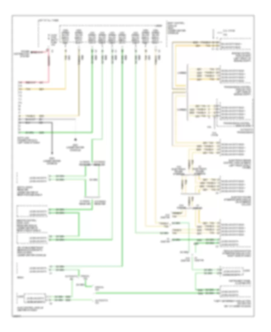
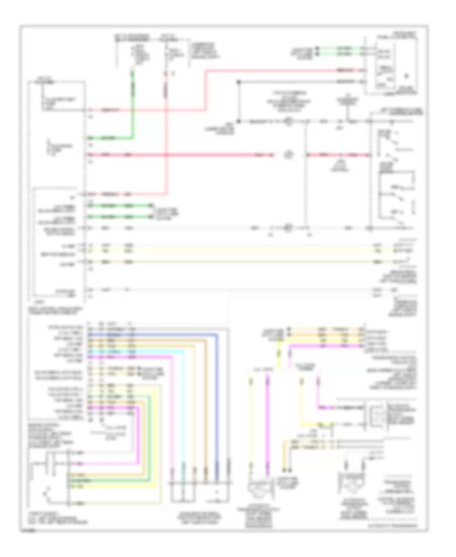
COMPUTER DATA LINES
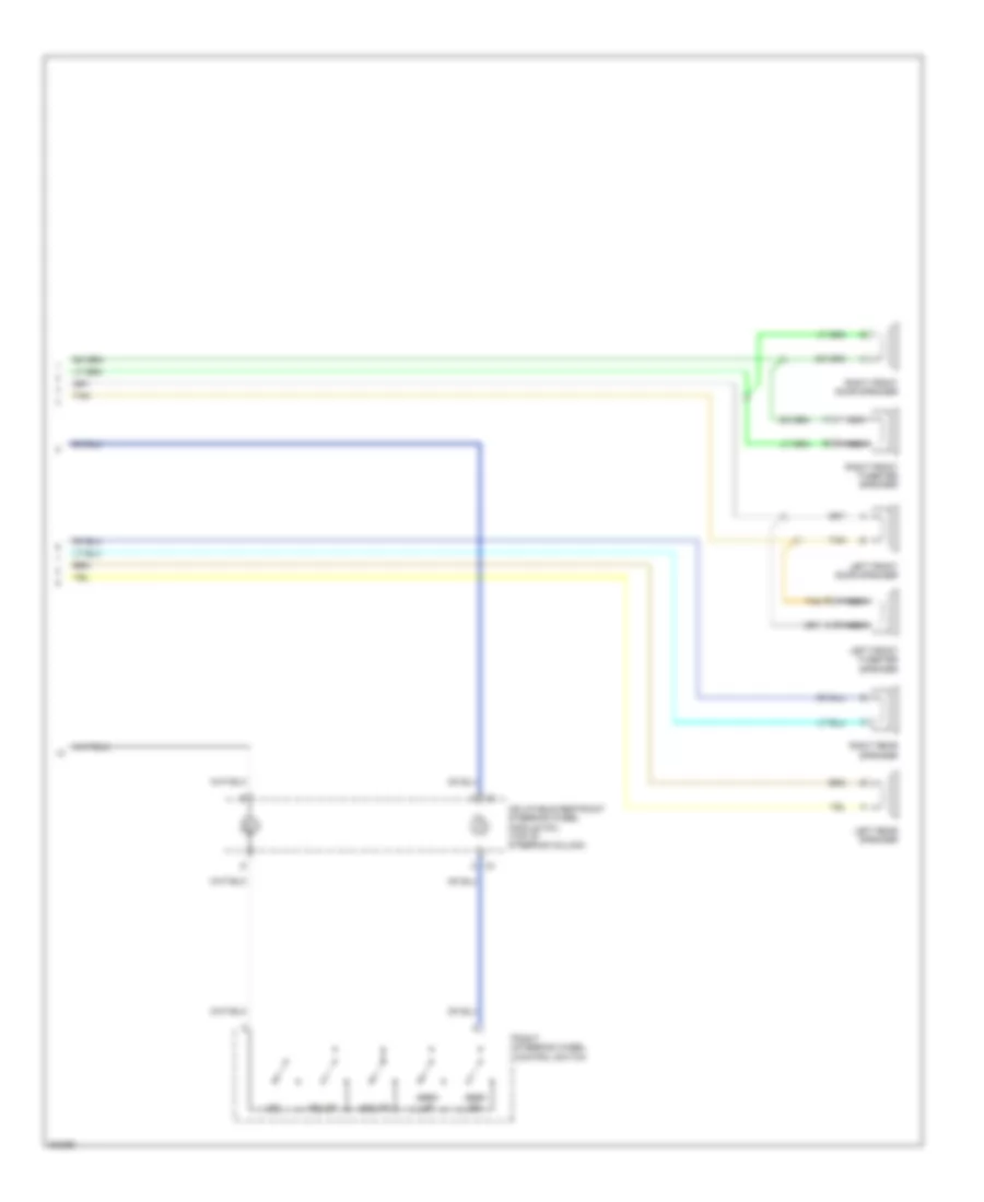
Computer Data Lines Wiring Diagram, Except Hybrid for Chevrolet Malibu LT 2009
List of elements for Computer Data Lines Wiring Diagram, Except Hybrid for Chevrolet Malibu LT 2009:
- 2.4l (vin b)
- 3.6l
- 4 speed
- 6 speed
- Automatic a/c
- Automatic transmission
- Body control module (bcm) (under center console)
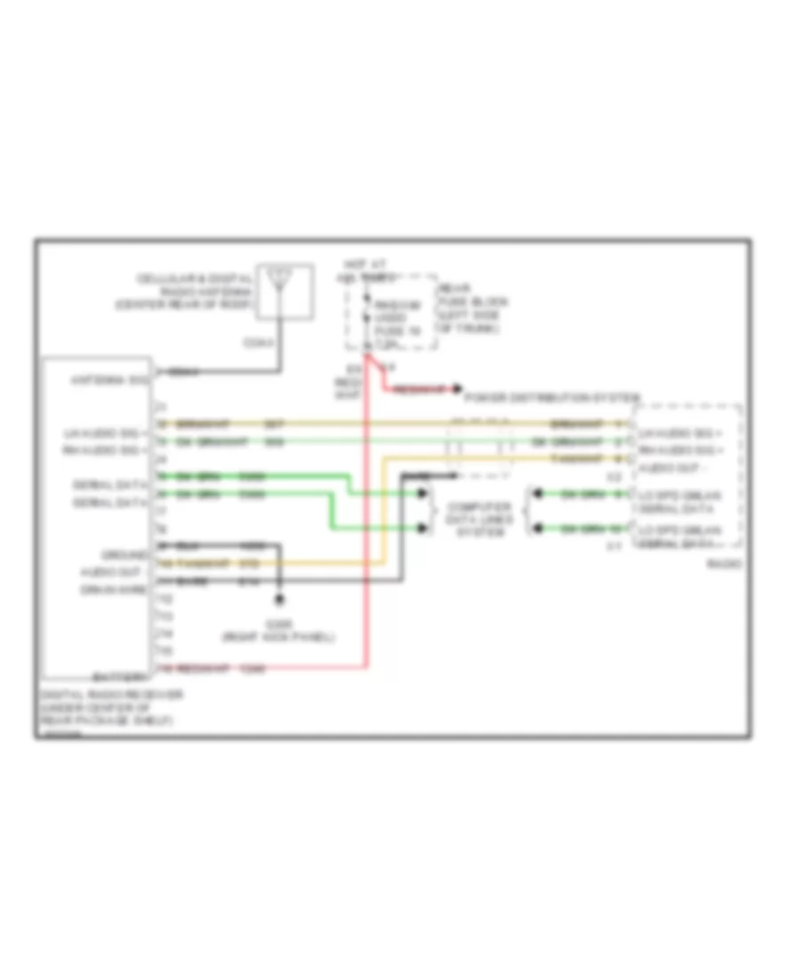
- Data link connector (dlc) (left side of dash)
- Digital radio receiver (under center of rear package shelf)
- Electric power steering (eps) module (on steering column)
- Electronic brake control module (ebcm) (left front strut tower)
- Engine control module (ecm) (left front of engine compt)
- G201 (under center console)
- G203 (under center console)
- Gmlan data bus +
- Gmlan data bus -
- High speed gmlan serial data bus +
- High speed gmlan serial data bus -
- Hot at all times
- Hs gmlan data bus +
- Hs gmlan data bus -
- Hvac control module (center of dash)
- Hvac ctrl (batt) fuse 10a
- Inflatable restraint sensing & diagnostic module (sdm) (under center console)
- Instrument panel cluster (ipc)
- Logic
- Low speed gmlan serial data
- Ls gmlan data
- Manual a/c
- Module (tcm)
- Onstar
- Power distribution system
- Radio
- Remote control door lock receiver (rcdlr) (under center of rear window shelf)
- Tan
- Theft deterrent module (tdm) (on ignition key cylinder housing)
- Transmission control
- Transmission control module (tcm) (left side of engine compt)
- Vehicle communication interface module (vcim) (right side of dash)
- W/ electronic power steering
- W/ onstar
- W/ radio receiver
- W/o electronic power steering
- W/o onstar
- W/o radio receiver
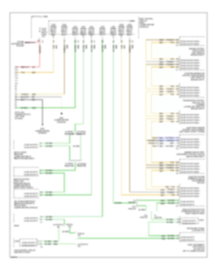
Computer Data Lines Wiring Diagram, Hybrid for Chevrolet Malibu LT 2009
List of elements for Computer Data Lines Wiring Diagram, Hybrid for Chevrolet Malibu LT 2009:
- Automatic a/c
- Body control module (bcm) (under center console)
- Data link connector (dlc) (left side of dash)
- Digital radio receiver (under center of rear package shelf)
- Electric power steering module (on steering column)
- Electronic brake control module (ebcm) (left front strut tower)
- Engine control module (ecm) (left rear of engine compt)
- G201 (under center console)
- G203 (under center console)
- Generator battery disconnect control module (behind rear seat)
- High speed gmlan serial data bus +
- High speed gmlan serial data bus -
- Hot at all times
- Hs gmlan data bus +
- Hs gmlan data bus -
- Hvac control module (center of dash)
- Hvac ctrl (batt) fuse 10a
- Inflatable restraint sensing & diagnostic module (sdm) (under center console)
- Instrument panel cluster (ipc)
- Logic
- Low speed gmlan serial data
- Ls gmlan data
- Manual a/c
- Power distribution system
- Radio
- Remote control door lock receiver (rcdlr) (under center of rear window shelf)
- Starter generator control module (sgcm) (left front of engine compt)
- Tan
- Theft deterrent (tdm) module (on ignition key cylinder housing)
- Transmission control module (tcm) (4 speed) (lower left front of engine compt)
- Vehicle communication interface module (vcim) (right side of dash)
- W/ onstar
- W/ radio receiver
- W/o onstar
- W/o radio receiver
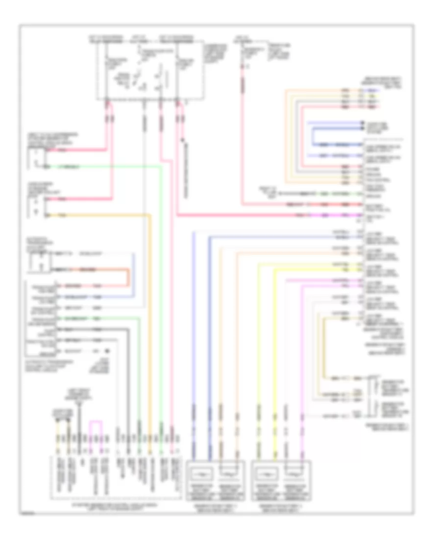
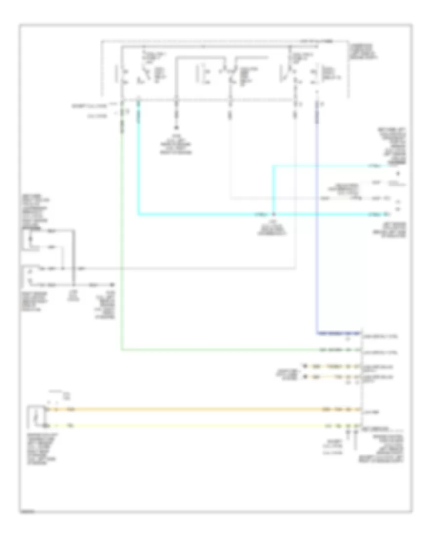
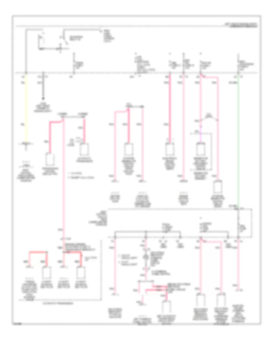
COOLING FAN
2.4L VIN 5
2.4L VIN 5, Cooling Fan Wiring Diagram for Chevrolet Malibu LT 2009
List of elements for 2.4L VIN 5, Cooling Fan Wiring Diagram for Chevrolet Malibu LT 2009:
- (355 mm from main breakout) (2.4l (vin 5)) j153
- (between left cooling fan & crankshaft position sensor) (2.4l (vin 5)) left engine cooling fan diode
- (between right cooling fan & a/c compressor breakout) (2.4l (vin 5)) right engine cooling fan diode
- 2.4l (vin b)
- 2.4l 3.6l
- 87a
- A11
- B10
- Computer data lines system
- Cool fan 1 fuse 17 30a
- Cool fan 2 fuse 18 30a
- Cool/ fan 1 relay
- Cool/ fan 2 relay 30
- Cool/fan ser/ par relay
- Ect sens sig
- Engine control module (ecm) (2.4l(vin 5): left rear of engine compt) (except 2.4l(vin 5): left front of engine compt)
- Engine coolant temperature (ect) sensor (2.4l: lower right rear of engine) (3.6l: left side of engine)
- Except 2.4l (vin b)
- G106 (2.4l: left rear of engine) (3.6l: right front of engine)
- High spd gmlan data +
- High spd gmlan data -
- High spd rly ctrl
- Hot at all times
- J151 (2.4l (vin 5)) (305 mm from main breakout)
- J152 (2.4l (vin 5))
- Left engine cooling fan (behind left side of radiator)
- Low ref
- Low spd rly ctrl
- Right engine cooling fan (behind right side of radiator)
- Tan
- Underhood fuse block (left side of engine compt)
2.4L VIN 5, Hybrid Cooling System Wiring Diagram for Chevrolet Malibu LT 2009
List of elements for 2.4L VIN 5, Hybrid Cooling System Wiring Diagram for Chevrolet Malibu LT 2009:
- (behind rear seat) generator battery vent fan
- (left front corner of engine compt) g101
- (middle rear of engine) heater coolant pump
- (next to a/c compressor) starter generator control module (sgcm) coolant pump
- (right "c" pillar) g301
- A trans pump driver error
- A12
- Automatic transmission auxiliary fluid pump
- Automatic transmission auxiliary fluid pump control module
- B pump control
- B10
- Bare
- Bas ign fuse 3 10a
- Bas pmps fuse 5 20a
- Battery positive vol
- C traction ctrl sw sig
- C12
- Computer data lines system
- Driver error
- Emission 2 fuse 5 10a
- Eng/tran cooling
- F trans pump low ref
- Fan control
- Fan tach feedback
- G trans pump high ref
- G107 (lower left side of engine)
- Gen batt temp sens 1a control
- Gen batt temp sens 1b control
- Gen batt temp sens 2a control
- Gen batt temp sens 2b control
- Gen batt temp sens 3a control
- Gen batt temp sens 3b control
- Generator battery 1 (behind rear seat)
- Generator battery 2 (behind rear seat)
- Generator battery 3 (behind rear seat)
- Generator battery assembly (behind rear seat)
- Generator battery disconnect control module
- Generator battery temperature sensor 1a
- Generator battery temperature sensor 1b
- Generator battery temperature sensor 2a
- Generator battery temperature sensor 2b
- Generator battery temperature sensor 3a
- Generator battery temperature sensor 3b
- Gnd
- Ground
- H trans pump sw control
- High speed gmlan
- High speed gmlan serial data +
- High speed gmlan serial data -
- High vol
- Hot at all times
- Hot w/ run/crank relay energized
- Ignition 1 vol
- Interlock loop sig
- Low ref
- Motor vol
- Nca
- Pnk
- Power
- Power distribution system
- Pump
- Pump control
- Rear fuse block (left side of trunk)
- Red
- Serial data -
- Starter generator control module (sgcm) (left front of engine compt)
- Tan
- Trans pmp mtr relay
- Trans pump
- Trans pump mtr fuse 52 20a
- Trans pump rly coil control
- Underhood fuse block (left side of engine compt)
- X1 serial data +
- X2 interlock loop sig
2.4L VIN B
2.4L VIN B, Cooling Fan Wiring Diagram for Chevrolet Malibu LT 2009
List of elements for 2.4L VIN B, Cooling Fan Wiring Diagram for Chevrolet Malibu LT 2009:
- (355 mm from main breakout) (2.4l (vin 5)) j153
- (between left cooling fan & crankshaft position sensor) (2.4l (vin 5)) left engine cooling fan diode
- (between right cooling fan & a/c compressor breakout) (2.4l (vin 5)) right engine cooling fan diode
- 2.4l (vin b)
- 2.4l 3.6l
- 87a
- A11
- B10
- Computer data lines system
- Cool fan 1 fuse 17 30a
- Cool fan 2 fuse 18 30a
- Cool/ fan 1 relay
- Cool/ fan 2 relay 30
- Cool/fan ser/ par relay
- Ect sens sig
- Engine control module (ecm) (2.4l(vin 5): left rear of engine compt) (except 2.4l(vin 5): left front of engine compt)
- Engine coolant temperature (ect) sensor (2.4l: lower right rear of engine) (3.6l: left side of engine)
- Except 2.4l (vin b)
- G106 (2.4l: left rear of engine) (3.6l: right front of engine)
- High spd gmlan data +
- High spd gmlan data -
- High spd rly ctrl
- Hot at all times
- J151 (2.4l (vin 5)) (305 mm from main breakout)
- J152 (2.4l (vin 5))
- Left engine cooling fan (behind left side of radiator)
- Low ref
- Low spd rly ctrl
- Right engine cooling fan (behind right side of radiator)
- Tan
- Underhood fuse block (left side of engine compt)
3.6L VIN 7
3.6L VIN 7, Cooling Fan Wiring Diagram for Chevrolet Malibu LT 2009
List of elements for 3.6L VIN 7, Cooling Fan Wiring Diagram for Chevrolet Malibu LT 2009:
- (355 mm from main breakout) (2.4l (vin 5)) j153
- (between left cooling fan & crankshaft position sensor) (2.4l (vin 5)) left engine cooling fan diode
- (between right cooling fan & a/c compressor breakout) (2.4l (vin 5)) right engine cooling fan diode
- 2.4l (vin b)
- 2.4l 3.6l
- 87a
- A11
- B10
- Computer data lines system
- Cool fan 1 fuse 17 30a
- Cool fan 2 fuse 18 30a
- Cool/ fan 1 relay
- Cool/ fan 2 relay 30
- Cool/fan ser/ par relay
- Ect sens sig
- Engine control module (ecm) (2.4l(vin 5): left rear of engine compt) (except 2.4l(vin 5): left front of engine compt)
- Engine coolant temperature (ect) sensor (2.4l: lower right rear of engine) (3.6l: left side of engine)
- Except 2.4l (vin b)
- G106 (2.4l: left rear of engine) (3.6l: right front of engine)
- High spd gmlan data +
- High spd gmlan data -
- High spd rly ctrl
- Hot at all times
- J151 (2.4l (vin 5)) (305 mm from main breakout)
- J152 (2.4l (vin 5))
- Left engine cooling fan (behind left side of radiator)
- Low ref
- Low spd rly ctrl
- Right engine cooling fan (behind right side of radiator)
- Tan
- Underhood fuse block (left side of engine compt)
CRUISE CONTROL
Cruise Control Wiring Diagram for Chevrolet Malibu LT 2009
List of elements for Cruise Control Wiring Diagram for Chevrolet Malibu LT 2009:
- (top of steering column) inflatable restraint steering wheel module coil
- 2.4l (vin 5)
- 2.4l (vin 5) & 3.6l
- 2.4l (vin b)
- 2.4l (vin b) 4 speed
- 3.6l
- 5 volt ref 1
- 5 volt ref 2
- 5v ref
- Accelerator pedal position sensor (app) (left side of dash)
- App sens 1 sig
- App sens 2 sig
- Automatic transmission
- Automatic transmission output shaft speed (oss) sensor
- Automatic transmission output shaft speed (oss) sensor (in automatic transmission)
- Body control module (bcm) (under center console)
- Brake pedal position sensor (left side of dash)
- Brk pos sens sig
- Cluster/theft fuse 10a
- Computer data lines system
- Control solenoid valve assembly (2.4l (vin b) 6 speed & 3.6l)
- Cruise control switch signal
- Cruise indicator
- Cruise on ind
- Cruise on/off switch
- D12
- Data bus +
- Data bus -
- Engine control module (ecm) (2.4l & 3.6l: left front of engine compt) (2.4l hybrid: left rear of engine compt
- G201 (under center console)
- Gmlan
- Gmlan serial data bus+
- Gmlan serial data bus-
- Gnd
- Hot at all times
- Hot w/ run/crank relay energized
- Ibcm (run/ crank) fuse 21 30a
- Ibcm 1 fuse 20
- Ign
- Instrument panel cluster (ipc)
- J201
- J209 (w/ a/t control)
- Left steering wheel control switch
- Logic
- Low ref
- Low speed gmlan serial data
- Oss hi sig
- Oss lo sig
- Pnk
- Res +
- Run/crank fuse 2a
- Serial data
- Set -
- Stoplamp sw
- Stoplamp sw sig
- Tac motor ctrl 1
- Tac motor ctrl 2
- Tan
- Tap sens 1 sig
- Tap sens 2 sig
- Throttle body (2.4l: left side of engine (3.6l: top left rear of engine)
- Transmission control module (tcm)
- Transmission control module (tcm) (2.4l) (bas/4 speed mild hybrid: left side of engine compt) (4 speed: lower left front of engine compt)
- Underhood fuse block (left side of engine compt)
- W/ accessory control
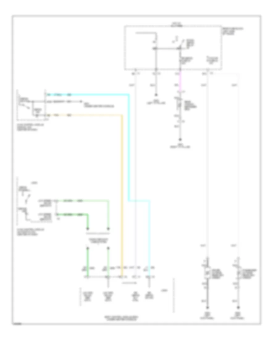
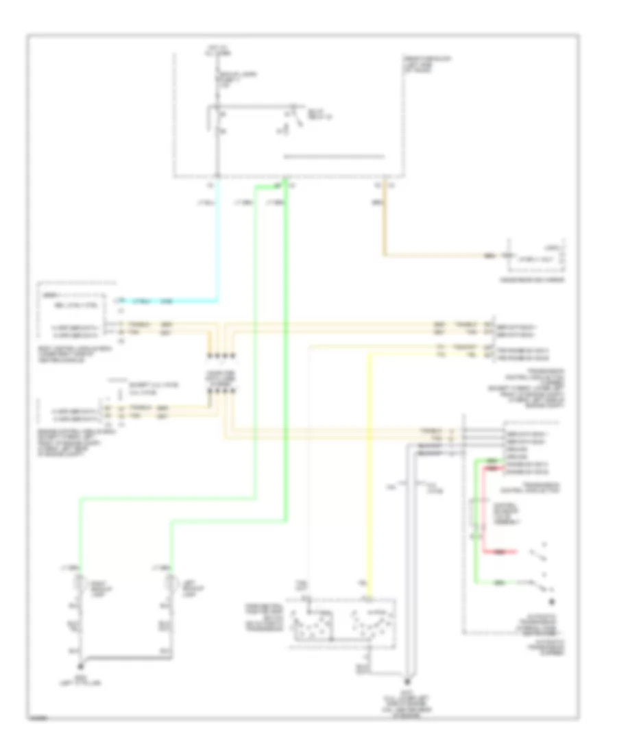
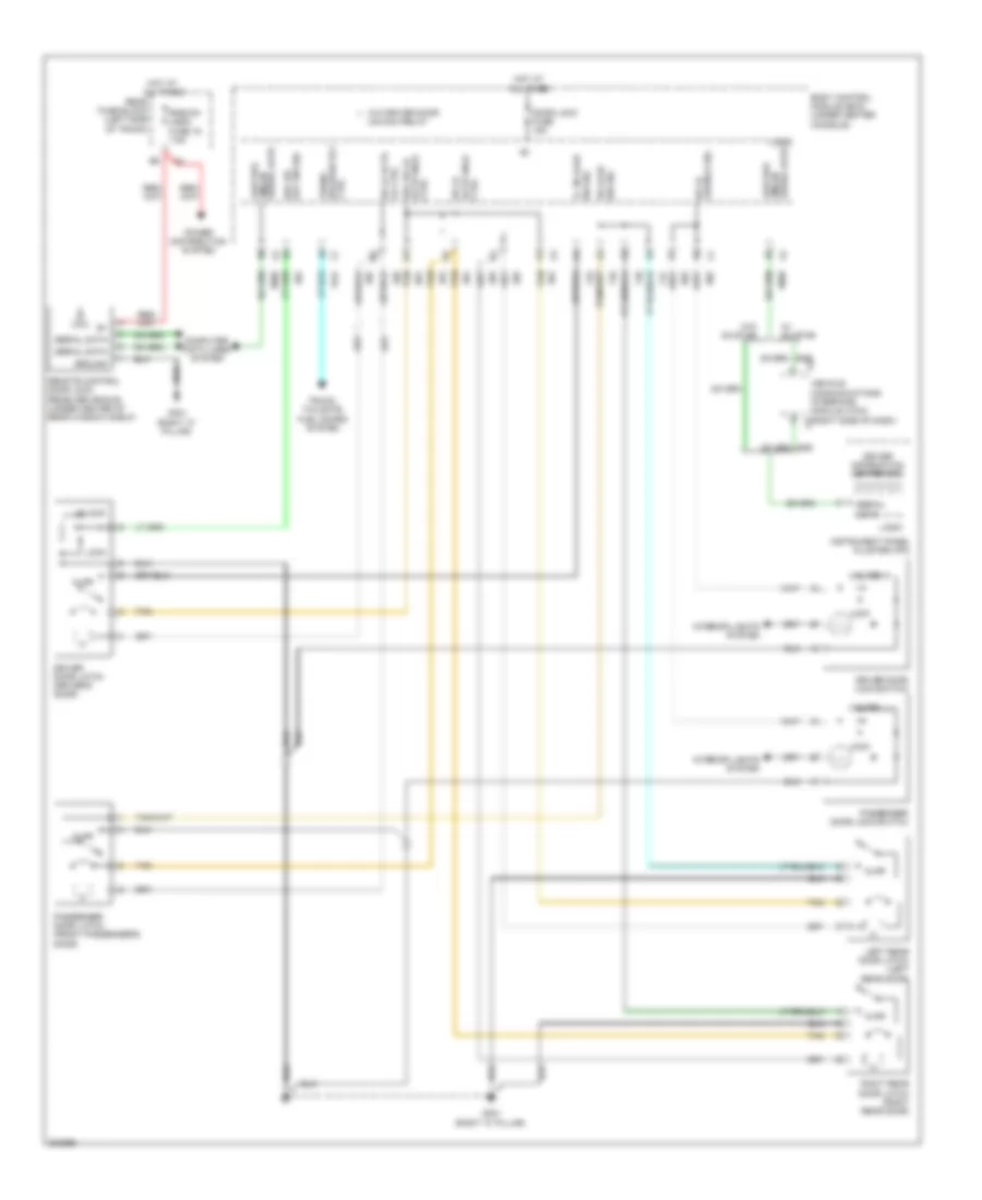
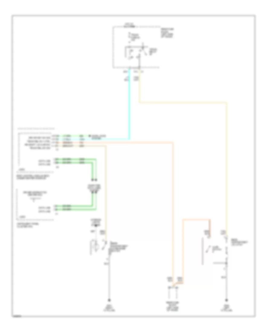
DEFOGGERS
Defoggers Wiring Diagram for Chevrolet Malibu LT 2009
List of elements for Defoggers Wiring Diagram for Chevrolet Malibu LT 2009:
- A12
- B12
- Body control module (bcm) (under center console)
- C12
- Computer data lines system
- Defog ind
- Defog switch
- Driver outside rearview mirror
- G201 (under center console)
- G301 (right "c" pillar)
- G302 (left "c" pillar)
- G303 (left kick panel)
- Hot at all times
- Htd mir fuse 24 10a
- Hvac control module (automatic a/c) (center of dash)
- Hvac control module (manual a/c) (center of dash)
- Logic
- Low spd gmlan ser data
- Low speed gmlan ser data
- Nca
- Passenger outside rearview mirror
- R/wdo defog relay
- Rear fuse block (left side of trunk)
- Rear window defogger grid
- Rr defog fuse 23 30a
- Rr defog rly ctrl
- Rr defog sw sig
- Tan
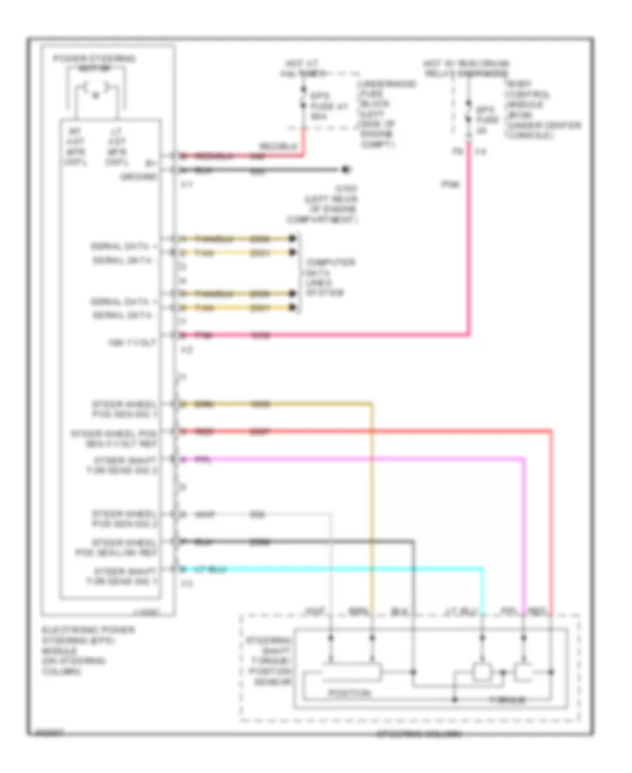
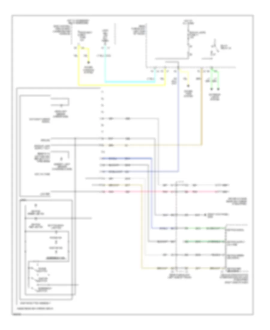
ELECTRONIC POWER STEERING
Electronic Power Steering Wiring Diagram for Chevrolet Malibu LT 2009
List of elements for Electronic Power Steering Wiring Diagram for Chevrolet Malibu LT 2009:
- Body control module (bcm) (under center console)
- Computer data lines system
- Electronic power steering (eps) module (on steering column)
- Eps fuse 2a
- Eps fuse 41 80a
- G103 (left rear of engine compartment)
- Ground
- Hot at all times
- Hot w/ run crank relay energized
- Ign 1 volt
- Logic
- Lt ast mtr cntl
- Pnk
- Position
- Power steering motor
- Red
- Rt ast mtr cntl
- Serial data +
- Serial data -
- Steer shaft tor sens sig 1
- Steer shaft tor sens sig 2
- Steer wheel pos sen 5 volt ref
- Steer wheel pos sen low ref
- Steer wheel pos sen sig 1
- Steer wheel pos sen sig 2
- Steering column
- Steering shaft torque/ position sensor
- Tan
- Torque
- Underhood fuse block (left side of engine compt)
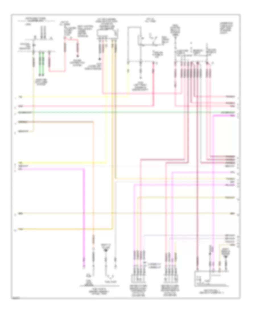
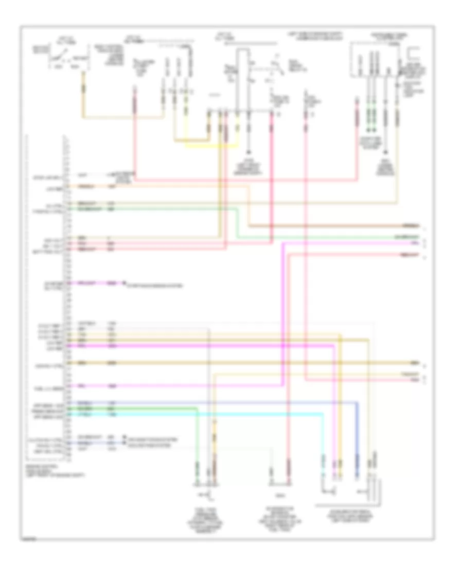
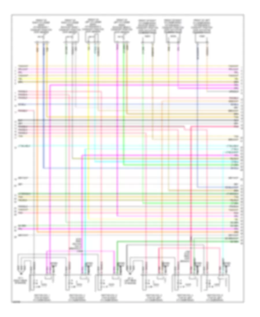
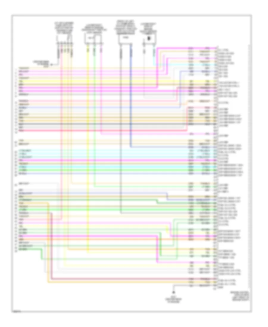
ENGINE PERFORMANCE
2.4L VIN 5
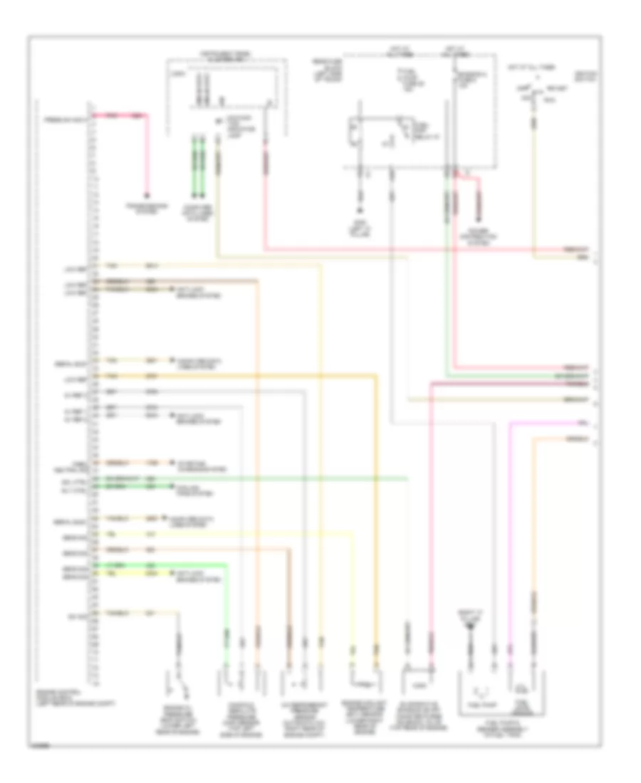
2.4L VIN 5, Engine Controls Wiring Diagram (1 of 4) for Chevrolet Malibu LT 2009
List of elements for 2.4L VIN 5, Engine Controls Wiring Diagram (1 of 4) for Chevrolet Malibu LT 2009:
- (right "c" pillar) g301
- 5v ref 1
- 5v ref 2
- A/c refrigerant pressure sensor (automatic a/c: right rear of engine compt)
- A10
- Acc
- Anti-lock brakes system
- Computer data lines system
- Cooling fans system
- Emission 2 fuse 5 10a
- Engine control module (ecm) (left rear of engine compt)
- Engine coolant temperature (ect) sensor (lower right rear of engine)
- Engine oil pressure (eop) switch (lower left rear of engine)
- Evaporative emission (evap) canister purge solenoid valve (top rear of engine)
- Fuel level sensor
- Fuel pump
- Fuel pump & sender assembly (in fuel tank)
- Fuel pump fuse 25 15a
- Fuel/ pmp relay 37
- G302 (left "c" pillar)
- Gmlan data
- Hot at all times
- Ign
- Ignition switch
- Instrument panel cluster (ipc)
- Logic
- Low ref
- Malfunc- tion indicator lamp
- Manifold absolute pressure (map) sensor (top left side of engine)
- Off
- Park/ neutral sig
- Pnk
- Power distribution system
- Press sw sig a
- Rear fuse block (left side of trunk)
- Rly ctrl
- Run
- Sens sig
- Serial bus+
- Serial bus-
- Sol ctrl
- Start
- Starting/ charging system
- Sw sig
- Tan
- Transmissions system
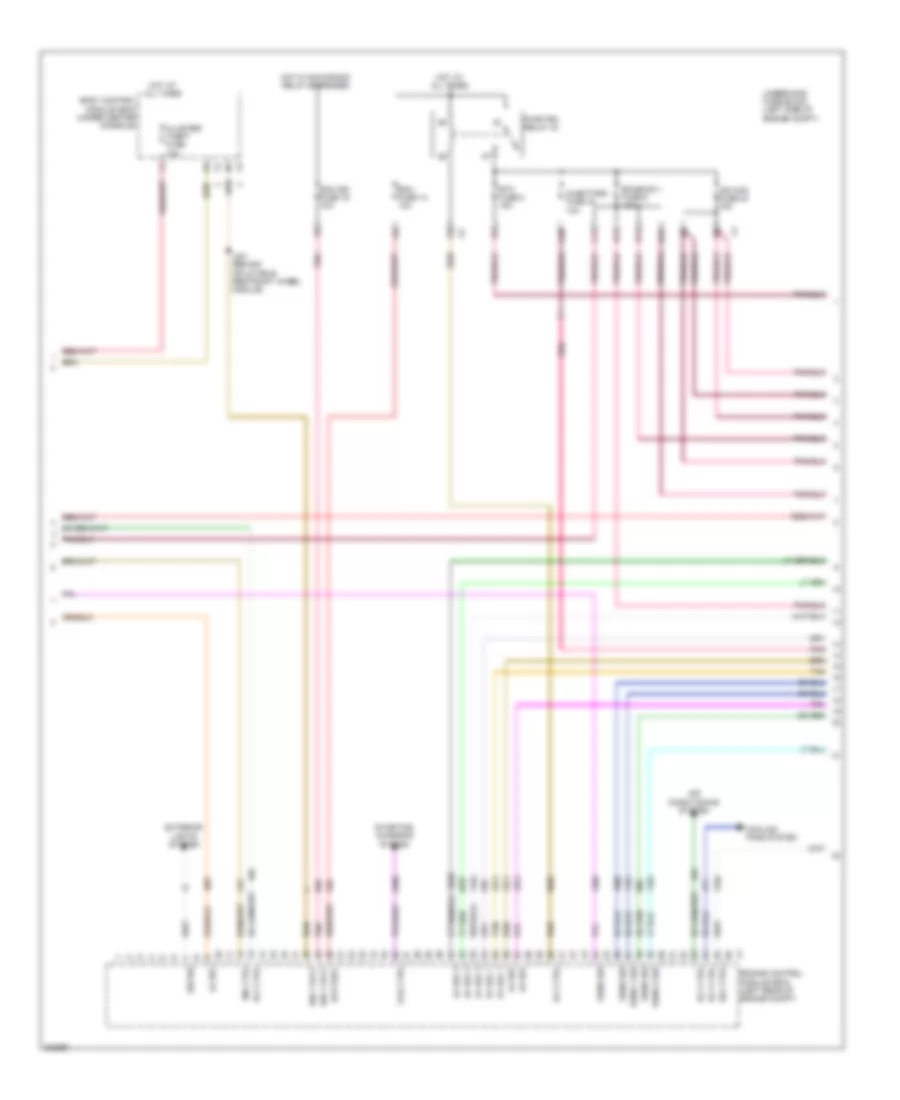
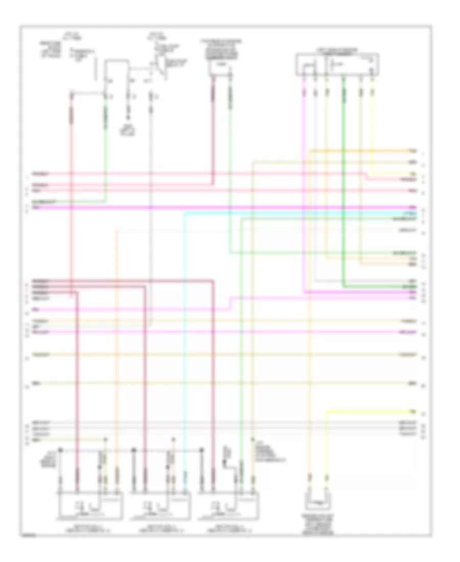
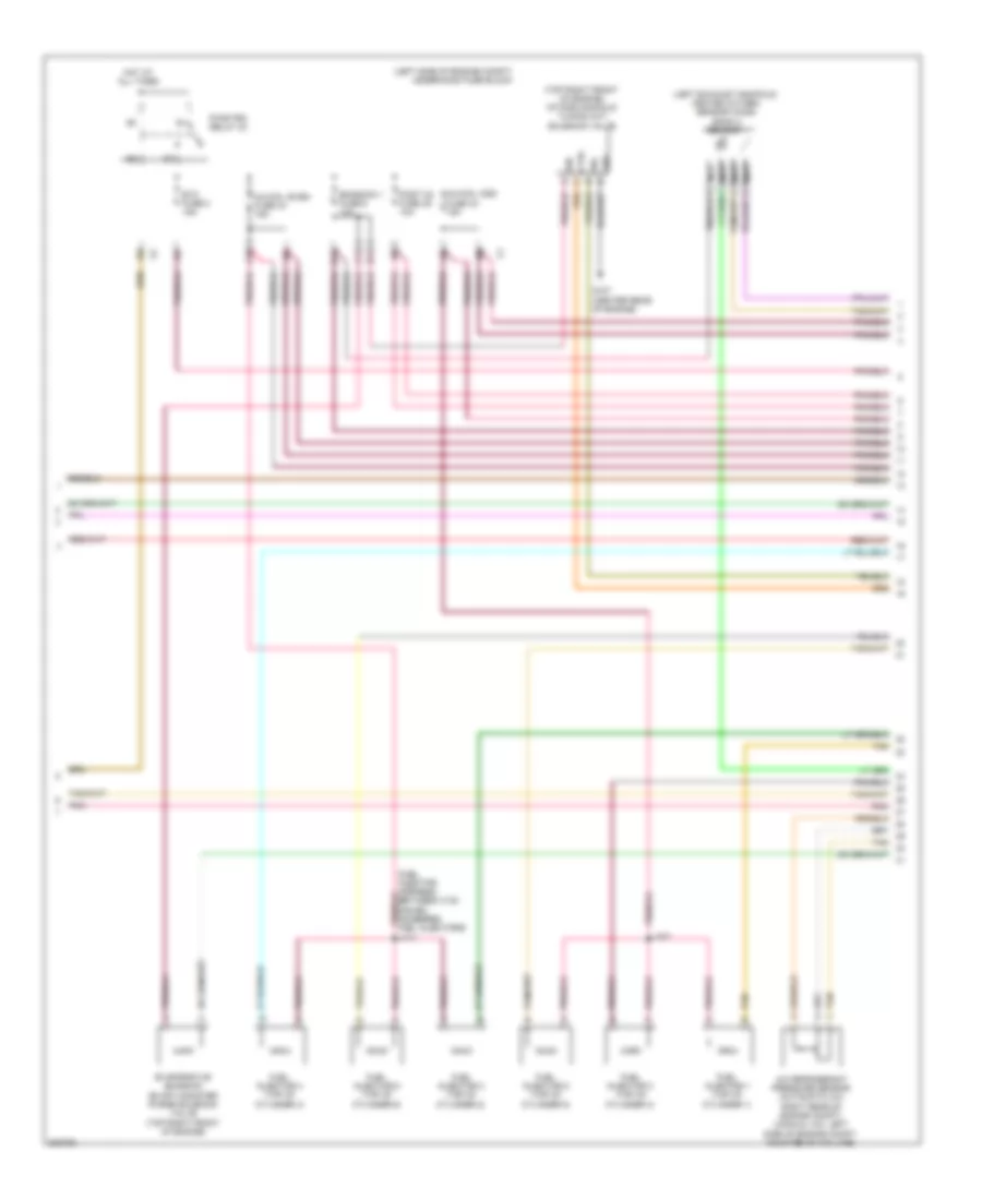
2.4L VIN 5, Engine Controls Wiring Diagram (2 of 4) for Chevrolet Malibu LT 2009
List of elements for 2.4L VIN 5, Engine Controls Wiring Diagram (2 of 4) for Chevrolet Malibu LT 2009:
- 5v ref 1
- 5v ref 2
- A10
- Air conditioning system
- B11
- Battery
- Body control module (bcm) (under center console)
- C11
- Cluster/ theft fuse 10a
- Coil ctrl
- Cooling fans system
- D11
- E11
- Ecm fuse 13 10a
- Ecm ign fuse 16 10a
- Emission 1 fuse 6 10a
- Engine control module (ecm) (left rear of engine compt)
- Etc fuse 2 15a
- Exterior lights system
- Hot at all times
- Hot w/ run/crank relay energized
- Ign 1 volt
- Ign mod fuse 43 15a
- Injectors fuse 44 10a
- J201 (behind inflatable restraint wheel module)
- Lo ref
- Lo ref 2
- Mil ctrl
- Pnk
- Pwr/trn relay 33
- Rly ctrl
- Sens 1 sig
- Sens 2 sig
- Sens sig
- Sol ctrl
- Starting/ charging system
- Sw sig
- Tan
- Underhood fuse block (left side of engine compt)
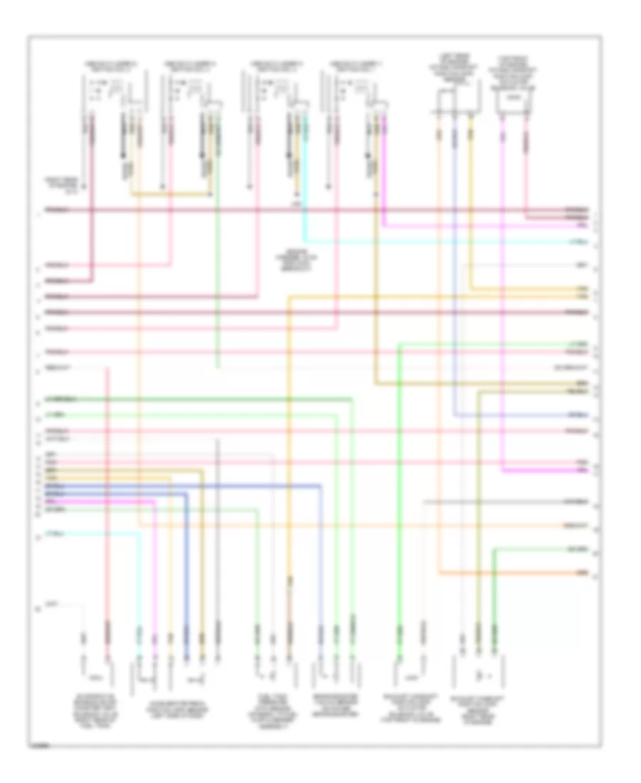
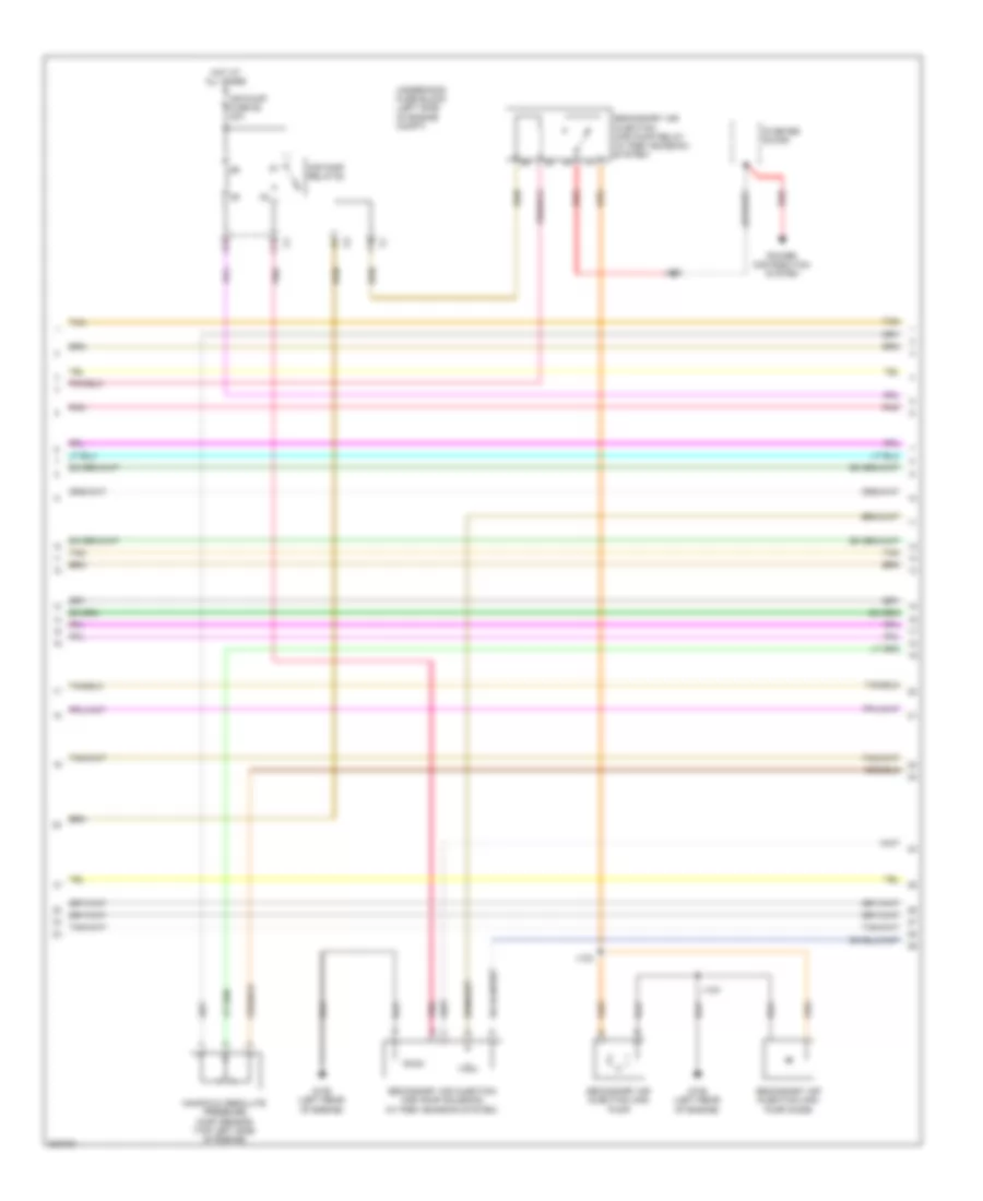
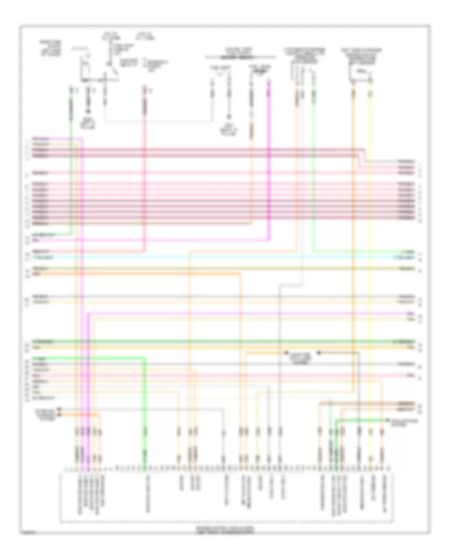
2.4L VIN 5, Engine Controls Wiring Diagram (3 of 4) for Chevrolet Malibu LT 2009
List of elements for 2.4L VIN 5, Engine Controls Wiring Diagram (3 of 4) for Chevrolet Malibu LT 2009:
- (above cylinder 1) ignition coil 1
- (above cylinder 2) ignition coil 2
- (above cylinder 3) ignition coil 3
- (above cylinder 4) ignition coil 4
- (engine harness, 40 mm from main breakout)
- (left rear of engine) intake camshaft position (cmp) sensor
- (right rear of engine) g110
- (top front of engine) intake camshaft position (cmp) actuator solenoid valve
- Accelerator pedal position (app) sensor (left side of dash)
- Brake booster vacuum sensor (on power brake booster)
- Evaporative emission (evap) canister vent solenoid valve (right rear of fuel tank)
- Exhaust camshaft position (cmp) actuator solenoid valve (top front of engine)
- Exhaust camshaft position (cmp) sensor (right rear of engine)
- Fuel tank pressure (ftp) sensor (integral to fuel pump & sender assembly)
- J121
- Nca
- Plug spark
- Pnk
- Spark plug
- Tan
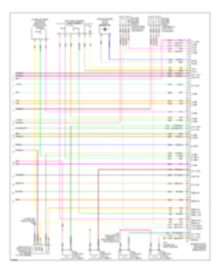
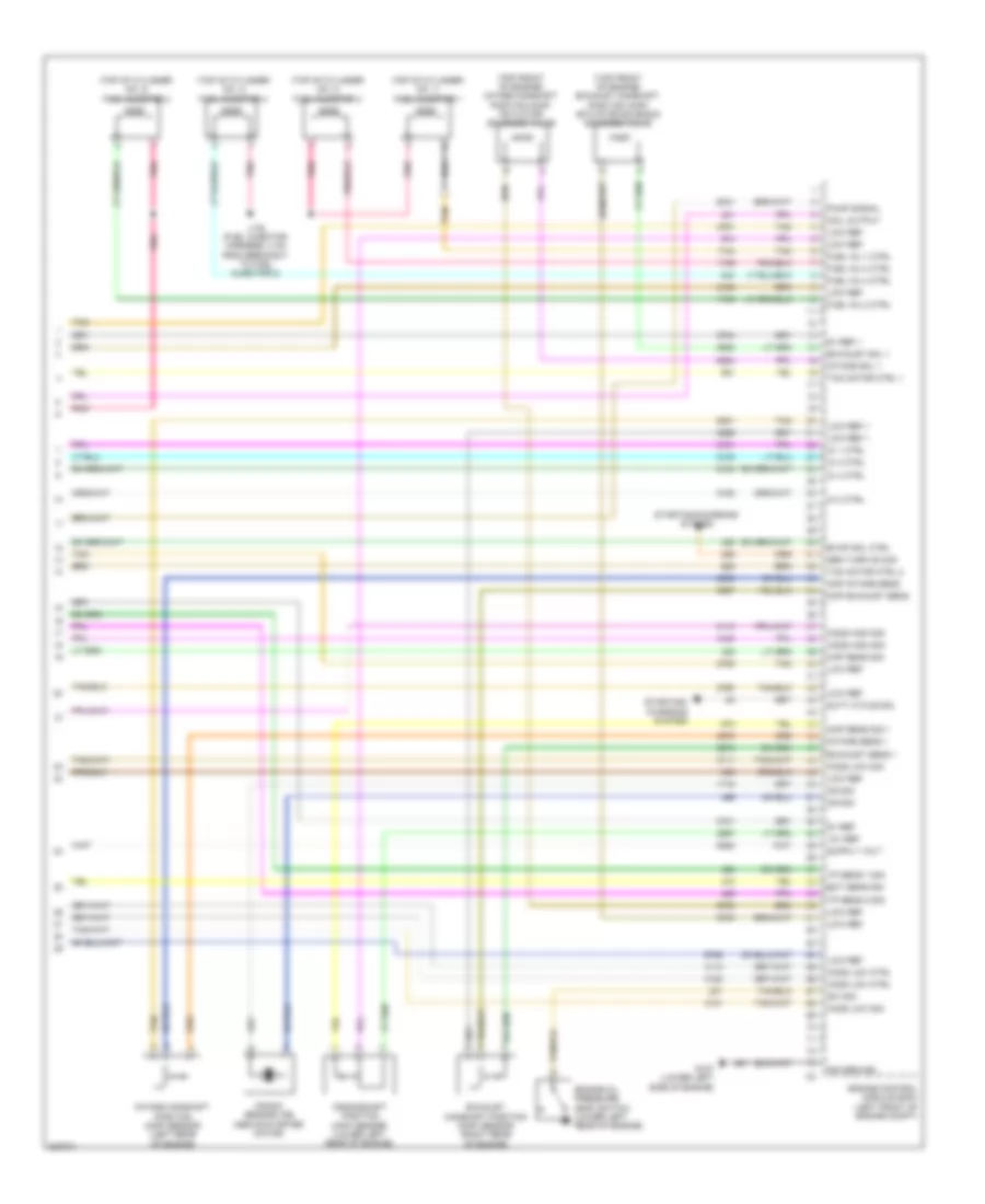
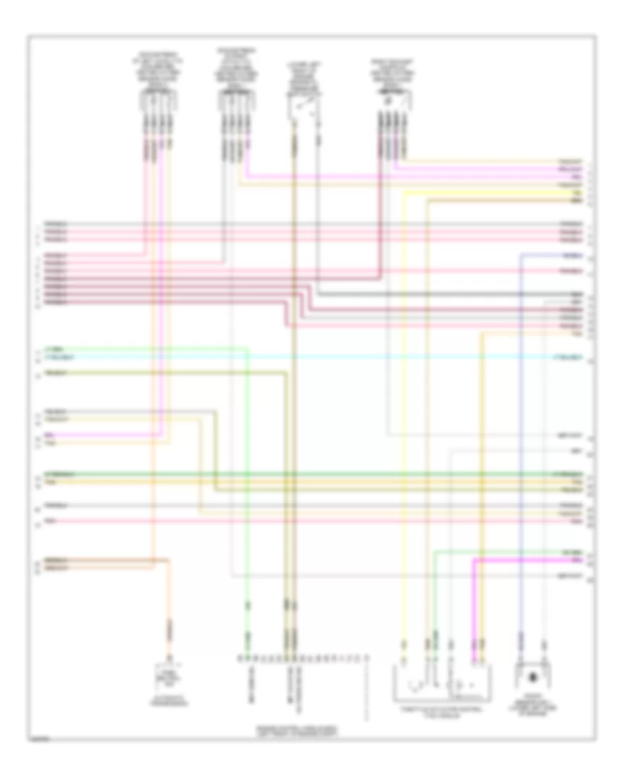
2.4L VIN 5, Engine Controls Wiring Diagram (4 of 4) for Chevrolet Malibu LT 2009
List of elements for 2.4L VIN 5, Engine Controls Wiring Diagram (4 of 4) for Chevrolet Malibu LT 2009:
- (above starter motor) knock sensor (ks)
- (left side of engine) throttle body
- (lower left rear of engine) crankshaft position (ckp) sensor
- (lower left side of engine) g107
- 5v ref 1
- 5v ref 2
- Cmp ctrl
- Ctrl 1
- Ctrl 2
- Ctrl sens 1
- Ctrl sens 2
- Engine control module (ecm) (left rear of engine compt)
- Fuel injector 1 (top of cylinder 1)
- Fuel injector 2 (top of cylinder 2)
- Fuel injector 3 (top of cylinder 3)
- Fuel injector 4 (top of cylinder 4)
- G107 (lower left side of engine)
- Gnd
- Ground
- Heated oxygen sensor (ho2s) 1 (upstream of catalytic converter)
- Heated oxygen sensor (ho2s) 2 (downstream of catalytic converter)
- Hi sig
- Ic 1 ctrl
- Ic 2 ctrl
- Ic 3 ctrl
- Ic 4 ctrl
- Ign
- Ign 1 volt
- Inj 1 ctrl
- Inj 2 ctrl
- Inj 3 ctrl
- Inj 4 ctrl
- J130 (fuel injector harness, 4 cm from breakout to fuel injector 2)
- Ks sig
- Lo ref
- Mass air flow (maf)/intake air temperature (iat) sensor (at air cleaner)
- Nca
- Pnk
- Sens 1 sig
- Sens 2 sig
- Sens sig
- Sig
- Tan
2.4L VIN 5, Hybrid System Wiring Diagram (1 of 3) for Chevrolet Malibu LT 2009
List of elements for 2.4L VIN 5, Hybrid System Wiring Diagram (1 of 3) for Chevrolet Malibu LT 2009:
- (engine harness, 100 mm from inline to transmission breakout) j103
- (engine harness, 80 mm from starter generator x2 breakout)
- (left front corner of engine compt) g101
- (not used)
- 12v
- 36-volt
- A nca
- Ajar sw sig
- Anti-theft system
- Bas batt fuse 51 10a
- Bas ign fuse 3 10a
- Battery
- Battery pos
- Closed sw sig
- Computer data lines system
- Drain wire
- Emission 2 fuse 5 10a
- Eng/tran cooling
- Fuse 175a
- Ground
- Hi serial bus +
- Hi serial bus -
- Hot at all times
- Hot w/ run/crank relay energized
- Ign 1 volt
- J nca
- J101 (engine harness, 50 mm from inline to transmission breakout)
- J102
- J105 (engine harness, 30 mm from tac module breakout)
- K nca
- Logic
- Loop sig
- Low ref
- Motor +
- Motor -
- Motor positive
- Nca
- Pnk
- Power distribution system
- Pump ctrl
- Pump mtr volt
- Pump rly coil
- Rear fuse block (left side of trunk)
- Red
- Shield
- Sig 1
- Sig 2
- Sig 3
- Sig 4
- Starter generator (lower left front of engine)
- Starter generator control module (sgcm) (left front of engine compt)
- Stud u
- Stud v
- Stud w
- Tan
- Temperature sig
- Trans pump drv
- Turn on sig
- Underhood fuse block (left side of engine compt)
- Water pump sply
2.4L VIN 5, Hybrid System Wiring Diagram (2 of 3) for Chevrolet Malibu LT 2009
List of elements for 2.4L VIN 5, Hybrid System Wiring Diagram (2 of 3) for Chevrolet Malibu LT 2009:
- (middle rear of engine) heater coolant pump
- (next to a/c compressor) starter generator control module (sgcm) coolant pump
- A trans pump driver error
- A12
- Automatic transmission auxiliary fluid pump
- Automatic transmission auxiliary fluid pump control module
- B pump control
- B10
- Bas pmps fuse 5 20a
- C pump motor vol
- C12
- F trans pump low ref
- G trans pump high ref
- G107 (lower left side of engine)
- Generator battery 1
- Generator battery 2
- Generator battery 3
- Generator battery temperature sensor 1a
- Generator battery temperature sensor 1b
- Generator battery temperature sensor 2a
- Generator battery temperature sensor 2b
- Generator battery temperature sensor 3a
- Generator battery temperature sensor 3b
- Ground
- H trans pump sw control
- Hot at all times
- Nca
- Pnk
- Red
- Tan
- Trans pmp mtr relay
- Trans pump mtr fuse 52 20a
- Underhood fuse block (left side of engine compt)
2.4L VIN 5, Hybrid System Wiring Diagram (3 of 3) for Chevrolet Malibu LT 2009
List of elements for 2.4L VIN 5, Hybrid System Wiring Diagram (3 of 3) for Chevrolet Malibu LT 2009:
- (info not available)
- 200a
- 36-volt
- 5 volt ref
- B+ 1
- B+ 2
- B+ 3
- Battery current sensor
- Battery disconnect switch
- Battery pos voltage
- Computer data lines system
- Fan ctrl
- Fan tach feedback
- G301 (right "c" pillar)
- G402 (right side of battery storage compt)
- Generator 1a ctrl
- Generator 1b ctrl
- Generator 2a ctrl
- Generator 2b ctrl
- Generator 3a ctrl
- Generator 3b ctrl
- Generator battery 1
- Generator battery 2
- Generator battery 3
- Generator battery assembly
- Generator battery disconnect control module
- Generator battery fuse
- Generator battery vent fan (behind rear seat)
- Gnd
- High speed gmlan bus+
- High speed gmlan bus-
- Ign 1 volt
- J410
- Link volt
- Low ref
- Low side pwm
- Main contactor relay
- Nca
- Pnk
- Power
- Red
- Sensor sig
- Sply volt
- Sw cntrl
- Tan
2.4L VIN B
2.4L VIN B, Engine Performance Wiring Diagram (1 of 5) for Chevrolet Malibu LT 2009
List of elements for 2.4L VIN B, Engine Performance Wiring Diagram (1 of 5) for Chevrolet Malibu LT 2009:
- 5v ref 1
- 5v ref 2
- A/c refrigerant pressure sensor (automatic a/c: right rear of engine compt)
- A/c relay ctrl
- A/c sens sig
- Acc
- Acc vol
- Accelerator pedal position (app) sensor (left side of dash)
- Accessory volt
- Air conditioning system
- Air pump rly ctrl
- App sens 1 sig
- App sens 2 sig
- Battery volt
- Body control logic module (bcm) (under center console)
- Computer data lines system
- Cooling fans system
- Ctrl coil
- D12
- Ecm fuse 13 10a
- Engine control module (ecm) (left front of engine compt)
- Etc fuse 2 15a
- Evap vent ctrl
- Evaporative emission (evap) canister vent solenoid valve (right rear of fuel tank)
- Exterior lights system
- Fan relay ctrl
- Fuel sens sig
- Fuel tank pressure (ftp) sensor (integral to fuel pump & sender assembly)
- Hot at all times
- Iat sens sig
- Ign 1 volt
- Ign lock ctrl
- Ignition switch
- Low ref
- Maf sens sig
- Mil ctrl
- Off
- Pnk
- Power distribution system
- Pwr/trn relay 33
- Relay ctrl
- Run
- Sens sig
- Ser data bus+
- Ser data bus-
- Start
- Starter enable relay ctrl
- Starting/charging system
- Tan
- Tan c
- To emission fuse 6 (diagram 2 of 4)
- Underhood fuse block (left side of engine compt)
2.4L VIN B, Engine Performance Wiring Diagram (2 of 5) for Chevrolet Malibu LT 2009
List of elements for 2.4L VIN B, Engine Performance Wiring Diagram (2 of 5) for Chevrolet Malibu LT 2009:
- (at air cleaner) mass air flow (maf)/ intake air temperature (iat) sensor
- (right "c" pillar) g301
- (right rear of engine) g110
- 4 speed a/t
- 6 speed a/t
- A10
- B11
- Body control module (bcm) (under center console)
- C10
- C11
- Cluster/ theft fuse 10a
- Computer data lines system
- D11
- E11
- Ecm ign fuse 16 10a
- Emission 1 fuse 6 10a
- From pwr/trn relay 33 (diagram 1 of 4)
- Fuel level sensor
- Fuel pump
- Fuel pump & sender assembly (in fuel tank)
- G107 (lower left side of engine)
- G109 (left front corner of engine compt)
- Gmlan data
- Heated oxygen sensor (ho2s) 1 (upstream of catalytic converter)
- Heated oxygen sensor (ho2s) 2 (downstream of catalytic converter)
- Hot at all times
- Ign
- Ign mod fuse 43 15a
- Ignition coil 1 (above cylinder no. 1)
- Injectors fuse 44 10a
- Instrument panel cluster (ipc)
- Logic
- Malfunc- tion indicator
- Nca
- Plug spark
- Pnk
- Power distribution system
- Run/ crank relay
- Tan
- Underhood fuse block (left side of engine compt)
2.4L VIN B, Engine Performance Wiring Diagram (3 of 5) for Chevrolet Malibu LT 2009
List of elements for 2.4L VIN B, Engine Performance Wiring Diagram (3 of 5) for Chevrolet Malibu LT 2009:
- (left side of engine) throttle body
- (top rear of engine) evaporative emission (evap) canister purge solenoid valve
- A10
- Emission 2 fuse 5 10a
- Engine coolant temperature (ect) sensor (lower right rear of engine)
- Fuel pump fuse 25 15a
- Fuel/pump relay 37
- G110 (right rear of engine)
- G302 (left "c" pillar)
- Hot at all times
- Ignition coil 2 (above cylinder no. 2)
- Ignition coil 3 (above cylinder no. 3)
- Ignition coil 4 (above cylinder no. 4)
- J121 (engine harness, 40 mm from main breakout)
- Nca
- Plug spark
- Pnk
- Rear fuse block (left side of trunk)
- Tan
2.4L VIN B, Engine Performance Wiring Diagram (4 of 5) for Chevrolet Malibu LT 2009
List of elements for 2.4L VIN B, Engine Performance Wiring Diagram (4 of 5) for Chevrolet Malibu LT 2009:
- A12
- Air pump fuse 52 30a
- Air pump relay 53
- C12
- F10
- G106 (left rear of engine)
- Hot at all times
- J122
- J123
- J124
- Manifold absolute pressure (map) sensor (top left side of engine)
- Pnk
- Power distribution system
- Red
- Secondary air injection (air) pump
- Secondary air injection (air) pump diode
- Secondary air injection (air) pump relay (w/ pzev emission system)
- Secondary air injection (air) pump solenoid (w/ pzev emission system)
- Starter motor
- Tan
- Underhood fuse block (left side of engine compt)
2.4L VIN B, Engine Performance Wiring Diagram (5 of 5) for Chevrolet Malibu LT 2009
List of elements for 2.4L VIN B, Engine Performance Wiring Diagram (5 of 5) for Chevrolet Malibu LT 2009:
- (top front of engine) exhaust camshaft position (cmp) actuator solenoid solenoid valve
- (top front of engine) intake camshaft position (cmp) actuator solenoid valve
- (top of cylinder no. 1) fuel injector 1
- (top of cylinder no. 2) fuel injector 2
- (top of cylinder no. 3) fuel injector 3
- (top of cylinder no. 4) fuel injector 4
- 12v ref
- 5v ref
- 5v ref 1
- Ckp sens sig 1
- Cmp exhaust sens
- Cmp intake sens
- Coil output
- Crankshaft position (ckp) sensor (lower left rear of engine)
- Duty cycle sig
- Ect sens sig
- Engine control module (ecm) (left front of engine compt)
- Engine oil pressure (eop) switch (lower left rear of engine)
- Evap sol ctrl
- Exhaust camshaft position (cmp) sensor (right rear of engine)
- Exhaust sens 1
- Exhaust sol 1
- Fuel inj 1 ctrl
- Fuel inj 2 ctrl
- Fuel inj 3 ctrl
- Fuel inj 4 ctrl
- G107 (lower left side of engine)
- Gen turn on sig
- Ho2s high sig
- Ho2s low ctrl
- Ho2s low sig
- Ic 1 ctrl
- Ic 2 ctrl
- Ic 3 ctrl
- Ic 4 ctrl
- Intake camshaft position (cmp) sensor (left rear of engine)
- Intake sens 1
- Intake sol 1
- J130 (fuel injector harness, 4 cm from breakout to fuel injector 2)
- Knock sensor (ks) (above starter motor)
- Ks sig
- Low ref
- Low ref 1
- Map sens sig
- Pnk
- Pump signal
- Sig ground
- Starting/ charging system
- Starting/charging system
- Sw sig
- Tac motor ctrl 1
- Tac motor ctrl 2
- Tan
- Tp sens 1 sig
- Tp sens 2 sig
3.6L VIN 7
3.6L VIN 7, Engine Performance Wiring Diagram (1 of 6) for Chevrolet Malibu LT 2009
List of elements for 3.6L VIN 7, Engine Performance Wiring Diagram (1 of 6) for Chevrolet Malibu LT 2009:
- (left side of engine compt) underhood fuse block
- 5-volt ref 1
- 5-volt ref 2
- Acc
- Acc volt
- Accelerator pedal position (app) sensor (left side of dash)
- Air conditioning system
- App sens 1 sig
- App sens 2 sig
- B10
- Batt pos volt
- Body control module (bcm) (under center console)
- C10
- Cluster/ theft fuse 10a
- Clutch rly ctrl
- Computer data lines system
- Cooling fans system
- Driver information center (dic) display
- Ecm fuse 10a
- Ecm ign fuse 16 10a
- Engine control module (ecm) (left front of engine compt)
- Evaporative emission (evap) canister vent solenoid valve (right rear of fuel tank)
- Exterior lights system
- F pmp rly ctrl
- Fan rly ctrl
- Fuel lvl sens
- Fuel tank pressure (ftp) sensor (integral to fuel pump & sender assembly)
- G109 (left front corner of engine compt)
- G201 (under center console)
- Gmlan data
- Gnd
- Hot at all times
- Ign 1 volt
- Ignition switch
- Instrument panel cluster (ipc)
- Logic
- Low ref
- Maf fuse 5 10a
- Main rly ctrl
- Malfunc- tion indicator lamp
- Mil ctrl
- Off
- Pnk
- Press sens sig
- Rly coil ctrl
- Run
- Run/ crank relay 32
- Start
- Starter rly ctrl
- Starting/charging system
- Stop lmp sply
- Tan
- Vent sol ctrl
3.6L VIN 7, Engine Performance Wiring Diagram (2 of 6) for Chevrolet Malibu LT 2009
List of elements for 3.6L VIN 7, Engine Performance Wiring Diagram (2 of 6) for Chevrolet Malibu LT 2009:
- (left exhaust manifold) heated oxygen sensor (ho2s) bank 2 sensor 1
- (left side of engine compt) underhood fuse block
- (top right front of engine) intake manifold tuning (imt) solenoid valve
- A/c refrigerant pressure sensor (automatic a/c: right rear of engine compt) (manual a/c: left side of engine compt, mounted on a/c line)
- A10
- B11
- C11
- Ctrl c
- D11
- Emission 1 fuse 6 10a
- Etc fuse 2 15a
- Evaporative emission (evap) canister purge solenoid valve (top right front of engine)
- Fuel injector 1 (top of cylinder 1)
- Fuel injector 2 (top of cylinder 2)
- Fuel injector 3 (top of cylinder 3)
- Fuel injector 4 (top of cylinder 4)
- Fuel injector 5 (top of cylinder 5)
- Fuel injector 6 (top of cylinder 6)
- G107 (center rear of engine)
- Gnd b
- Hot at all times
- Ign a
- Inj/coil even fuse 44 15a
- Inj/coil odd fuse 43 15a
- J107
- J114
- Nca
- Pnk
- Post o2 fuse 45 10a
- Pwr/trn relay 33
- Sig d
- Tan
3.6L VIN 7, Engine Performance Wiring Diagram (3 of 6) for Chevrolet Malibu LT 2009
List of elements for 3.6L VIN 7, Engine Performance Wiring Diagram (3 of 6) for Chevrolet Malibu LT 2009:
- (in fuel tank) fuel pump & sender assembly
- (left side of engine) engine coolant temperature (ect) sensor
- (top rear of engine) manifold absolute pressure (map) sensor
- 5-volt ref 2
- A/c press sens sig
- A10
- Computer data lines system
- Cooling fans system
- Duty cycle sig
- Ect sens sig
- Emission 2 fuse 5 10a
- Engine control module (ecm) (left front of engine compt)
- Evap purge sol ctrl
- Fuel level sensor
- Fuel pump
- Fuel pump fuse 25 15a
- Fuel/pmp relay 37
- G301 (right "c" pillar)
- G302 (left "c" pillar)
- Gen turn on sig
- Gmlan data bus +
- Gmlan data bus -
- Ho2s hi sig bank 2
- Ho2s htr low ctrl
- Ho2s low sig bank 2
- Ho2s ref bank 2
- Hot at all times
- Imt valve ctrl
- Low ref
- Low sp fan rly ctrl
- Park/neutral sig
- Pnk
- Rear fuse block (left side of trunk)
- Starting/ charging system
- Tan
3.6L VIN 7, Engine Performance Wiring Diagram (4 of 6) for Chevrolet Malibu LT 2009
List of elements for 3.6L VIN 7, Engine Performance Wiring Diagram (4 of 6) for Chevrolet Malibu LT 2009:
- (downstream of left catalytic converter) heated oxygen sensor (ho2s) bank 2 sensor 2
- (downstream of right catalytic converter) heated oxygen sensor (ho2s) bank 1 sensor 2
- (lower left front of engine) engine oil pressure (eop) switch
- (right exhaust manifold) heated oxygen sensor (ho2s) bank 1 sensor 1
- Automatic transmission
- Engine control module (ecm) (left front of engine compt)
- Imt valve sig
- Knock sensor (ks) 1 (lower left side of engine)
- Map sens sig
- Nca
- Oil press sw sig
- Park neutral sig
- Pnk
- Tan
- Throttle actuator control (tac) module
3.6L VIN 7, Engine Performance Wiring Diagram (5 of 6) for Chevrolet Malibu LT 2009
List of elements for 3.6L VIN 7, Engine Performance Wiring Diagram (5 of 6) for Chevrolet Malibu LT 2009:
- (5 cm from ignition coil 5 breakout) j198
- (front of left cylinder bank) exhaust bank 2 camshaft position (cmp) sensor
- (front of left cylinder bank) intake bank 2 camshaft position (cmp) actuator solenoid valve
- (front of left cylinder bank) intake bank 2 camshaft position (cmp) sensor
- (front of right cylinder bank) exhaust bank 1 camshaft position (cmp) actuator solenoid valve
- (front of right cylinder bank) exhaust bank 1 camshaft position (cmp) sensor
- (front of right cylinder bank) intake bank 1 camshaft position (cmp) actuator solenoid valve
- (front of right cylinder bank) intake bank 1 camshaft position (cmp) sensor
- G111 (right rear of engine)
- G113 (left rear of engine)
- Ignition coil 1 (top of right cylinder bank)
- Ignition coil 2 (top of left cylinder bank)
- Ignition coil 3 (top of right cylinder bank)
- Ignition coil 4 (top of left cylinder bank)
- Ignition coil 5 (top of right cylinder bank)
- Ignition coil 6 (top of left cylinder bank)
- J199 (5 cm from main branch)
- Nca
- Pnk
- Pnk b
- Spark plug
- Tan
3.6L VIN 7, Engine Performance Wiring Diagram (6 of 6) for Chevrolet Malibu LT 2009
List of elements for 3.6L VIN 7, Engine Performance Wiring Diagram (6 of 6) for Chevrolet Malibu LT 2009:
- (at air cleaner) mass air flow (maf)/intake air temperature (iat) sensor
- (center rear of engine) g107
- (front of left cylinder bank) exhaust bank 2 camshaft position (cmp) actuator solenoid valve
- (lower right rear of engine) crankshaft position (ckp) sensor
- (lower right side of engine) knock sensor (ks) 2
- 12-v ref
- 5-v ref 2
- Ckp sens 1 sig
- Cmp act sol sig
- Cmp sens bank 1 exh
- Cmp sens bank 1 int
- Cmp sens bank 2 exh
- Cmp sens bank 2 int
- Cmp sig bank 1 ext
- Cmp sig bank 2 exh
- Cmp sig bank 2 int
- Cmp sol bank 1 exh
- Cmp sol bank 1 int
- Cmp sol bank 2 exh
- Cmp sol bank 2 int
- Engine control module (ecm) (left front of engine compt)
- Fuel inj 1 ctrl
- Fuel inj 2 ctrl
- Fuel inj 3 ctrl
- Fuel inj 4 ctrl
- Fuel inj 5 ctrl
- Fuel inj 6 ctrl
- G107 (center rear of engine)
- Gnd
- Ho2s hi sig
- Ho2s htr low ctrl
- Ho2s low sig
- Iat sens sig
- Ic 1 ctrl
- Ic 2 ctrl
- Ic 3 ctrl
- Ic 4 ctrl
- Ic 5 ctrl
- Ic 6 ctrl
- Ign 1 volt
- Ks 1 sig
- Ks 2 sig
- Low ref
- Low ref bank 1 int
- Low ref bank 2 exh
- Low ref bank 2 int
- Maf sens sig
- Map sens sig
- Pnk
- Tac motor ctrl 1
- Tac motor ctrl 2
- Tan
- Tp sens 1 sig
- Tp sens 2 sig
EXTERIOR LIGHTS
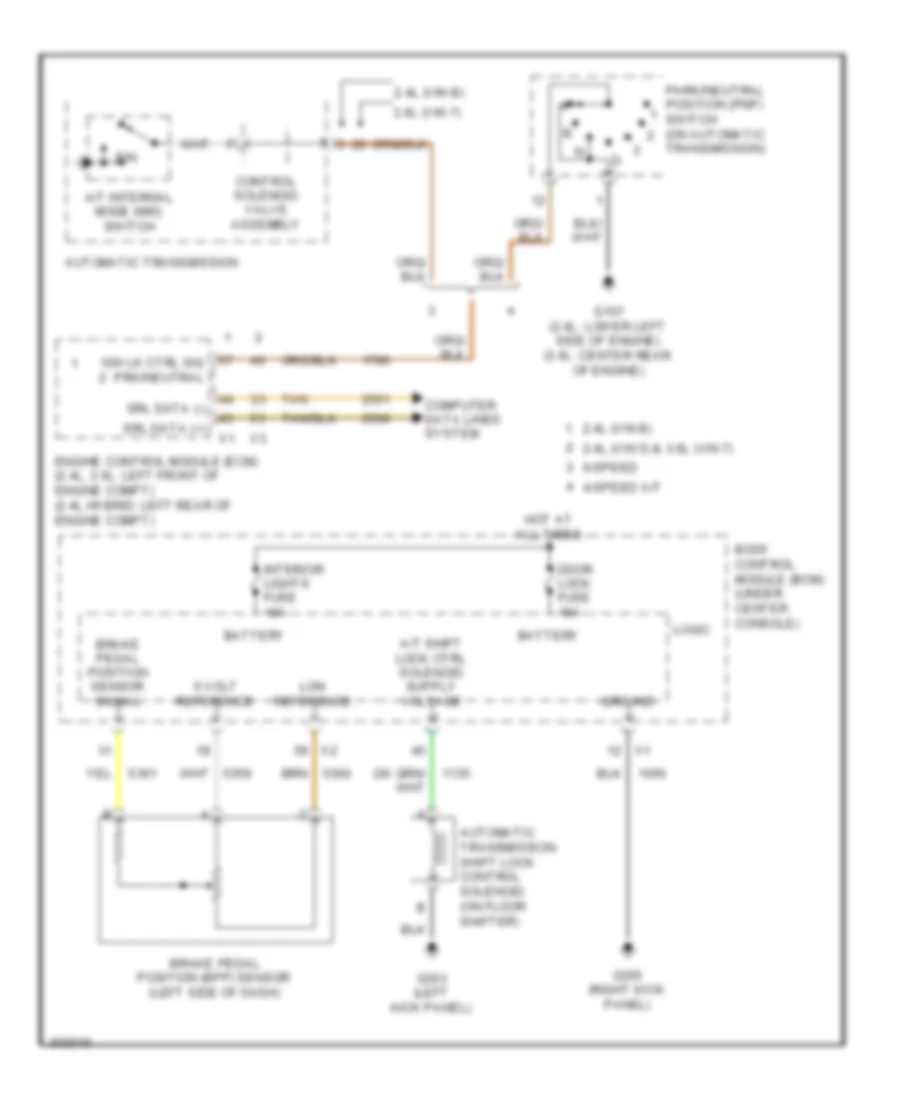
Backup Lamps Wiring Diagram for Chevrolet Malibu LT 2009
List of elements for Backup Lamps Wiring Diagram for Chevrolet Malibu LT 2009:
- 2.4l (vin b)
- 3.6l
- Automatic transmission (6 speed)
- Automatic transmission internal mode switch (ims)
- Bck/up lamps fuse 17 10a
- Body control module (bcm) (under right side of center console)
- Bu/lp relay 33
- Computer data lines system
- Control solenoid valve assembly
- Engine control module (ecm) (except hybrid: left front of engine compt) (hybrid: left rear of engine compt)
- Except 2.4l (vin b)
- G107 (2.4l: lower left side of engine) (3.6l: center rear of engine)
- G302 (left "c" pillar)
- Ground
- Hi spd ser data +
- Hi spd ser data -
- Hot at all times
- Inside rearview mirror
- Left backup lamp
- Logic
- Lp sply volt
- Park/neutral position (pnp) switch (on automatic transmission)
- Range sw sig a
- Range sw sig b
- Rear fuse block (left side of trunk)
- Red
- Rev lp rly ctrl
- Right backup lamp
- Ser data bus +
- Ser data bus -
- Tan
- Transmission control module (tcm)
- Transmission control module (tcm) (4 speed) (except hybrid: lower left front of engine compt) (hybrid: left side of engine compt)
- Trs range sw sig a
- Trs range sw sig b
Exterior Lamps Wiring Diagram (1 of 2) for Chevrolet Malibu LT 2009
List of elements for Exterior Lamps Wiring Diagram (1 of 2) for Chevrolet Malibu LT 2009:
- (w/ lz option package 1)
- 5v ref
- A12
- Auto
- Body control module (bcm) (under center console)
- Brake pedal position (bpp) sensor (left side of dash)
- Brk pos sens sig
- C12
- Computer data lines system
- Detection sig
- G101 (left front corner of engine compt)
- G102 (right front corner of engine compt)
- G201 (under center console)
- G203 (under center console)
- Gnd
- Hazard sw sig
- Hazard warning switch
- Head
- Hi spd ser data +
- Hi spd ser data -
- Hot at all times
- Interior lights system
- J109
- J110
- J112
- J113
- Left
- Left front marker lamp
- Left front repe- ater lamp
- Left park/ turn signal lamp
- Lf trn sig vlt
- Lo spd ser data bus
- Logic
- Low ref
- Lt trn sig sw
- Maj
- Min
- Off
- Park
- Prk lamps fuse 6 10a
- Prk lmp rly cntl
- Prk lmp sw on sig
- Prk lp relay 27
- Rear fuse block (left side of trunk)
- Rf trn sig vlt
- Right
- Right front marker lamp
- Right front repe- ater lamp
- Right park/ turn signal lamp
- Rt trn sig sw
- Tan
- Turn signal/ multi-function switch
- Underhood fuse block (left side of engine compt)
Exterior Lamps Wiring Diagram (2 of 2) for Chevrolet Malibu LT 2009
List of elements for Exterior Lamps Wiring Diagram (2 of 2) for Chevrolet Malibu LT 2009:
- 2.4l (vin b)
- 3.6l
- 4 speed
- 6 speed
- Automatic transmission
- Batt
- Body control module (bcm) (under center console)
- C1 x1
- C10
- C11
- Center high mounted stop lamp (chmsl)
- Cluster/ theft fuse 10a
- Computer data lines system
- E2 x2
- Engine control module (ecm) (except hybrid: left front of engine compt) (hybrid: left rear of engine compt)
- Except 2.4l (vin b)
- G109 (left front corner of engine compt)
- G302 (left "c" pillar)
- G401 (left rear of trunk)
- G403 (left rear of trunk)
- Gnd
- Hi spd ser data +
- Hi spd ser data -
- Hot at all times
- Instrument panel cluster (ipc)
- Left rear marker lamp
- Left tail/ stop & turn signal lamp
- Left tail/stop & turn signal lamp
- Left turn sig ind
- License lamp
- Logic
- Low spd ser data
- Maj
- Min
- Nca
- Power distribution system
- Right rear marker lamp
- Right tail/ stop & turn signal lamp
- Right tail/stop & turn signal lamp
- Right turn sig ind
- Stop lam sw sig
- Stop lmp sw sig
- Stop lp fuse 47 10a
- Stop lp relay 49
- Tan
- Transmission control module (tcm) (except hybrid: lower left front of engine compt) (hybrid: left side of engine compt)
- Underhood fuse block (left side of engine compt)
- W/ lz option package 1
- W/o lz option package 1
GROUND DISTRIBUTION
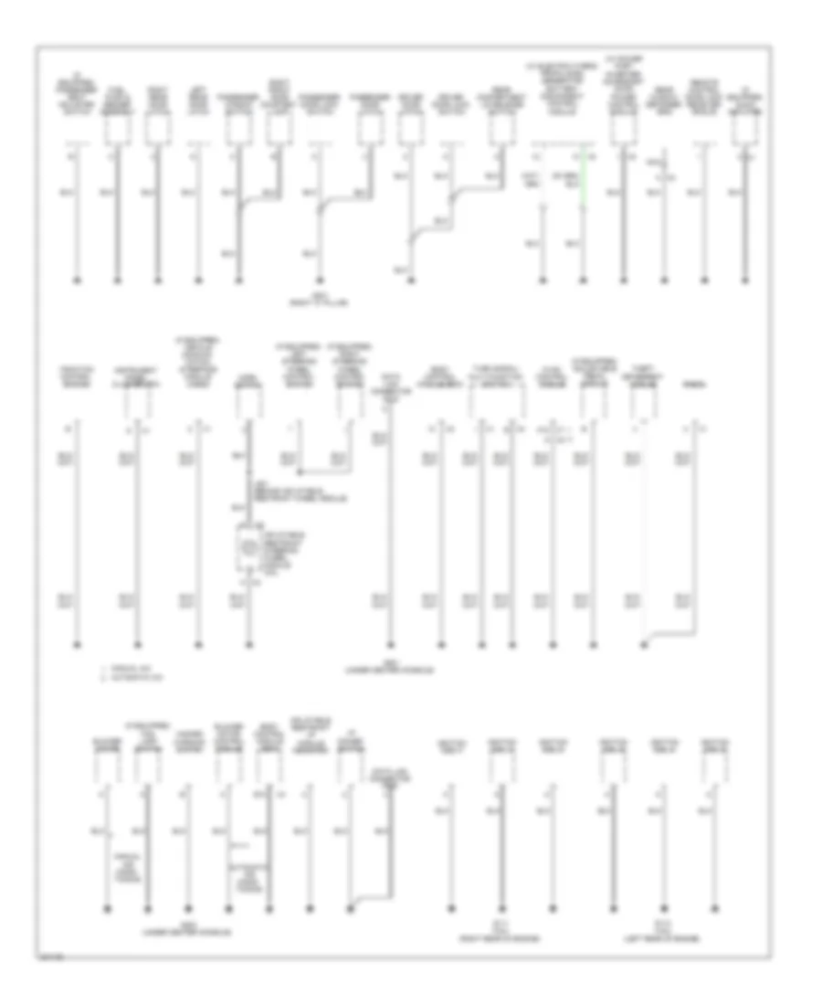
Ground Distribution Wiring Diagram (1 of 3) for Chevrolet Malibu LT 2009
List of elements for Ground Distribution Wiring Diagram (1 of 3) for Chevrolet Malibu LT 2009:
- (2.4l (vin 5) automatic transmission auxiliary fluid pump control module
- (2.4l (vin 5)) starter generator control module (scgm)
- (2.4l (vin b) (2.4l (vin 5) a/t) park/ neutral position (pnp) switch
- (3.6l) intake manifold tuning (imt) solenoid valve
- (if equipped) electric power steering (eps) module
- (if equipped) left front fog lamp
- (if equipped) right front fog lamp
- (left side of engine compt) underhood fuse block
- - x6
- 2.4l (vin 5)
- 2.4l (vin 5) & 2.4l (vin b)
- 2.4l (vin b) & 3.6l
- 3.6l
- 3.6l a/t (vin 7)
- 87a
- 90 mm from a/c compressor breakout)
- A x1
- A/c compressor clutch
- A3 x1
- Battery
- Body control module (bcm)
- Brake fluid level switch
- C10
- Cool/fan ser/par relay 29
- Electronic brake control module (ebcm)
- Engine control module (ecm)
- Frt fog relay 36
- G101 (left front corner of engine compt)
- G102 (right front corner of engine compt)
- G103 (left rear of engine compt)
- G104 (left front corner of engine compt)
- G105 (2.4l: lower left rear of engine) (3.6l: left side of engine)
- G106 (2.4l: left rear of engine) (3.6l: right front of engine)
- G107 (2.4l: lower left side of engine) (3.6l: center rear of engine)
- G109 (left front corner of engine compt)
- G402 (right side of battery storage compt)
- Generator battery assembly
- Gnd
- Hood ajar switch
- Horn assembly
- J109 (left headlamp wiring harness)
- J110
- J124
- Left front marker lamp
- Left front repeater lamp
- Left high beam headlamp
- Left low beam headlamp
- Left park/turn signal lamp
- Mass air flow (maf)/ intake air temperature (iat) sensor
- Nca
- Right engine cooling fan
- Right engine cooling fan diode
- Right front marker lamp
- Right front repeater lamp
- Right high beam headlamp
- Right low beam headlamp
- Right park/turn signal lamp
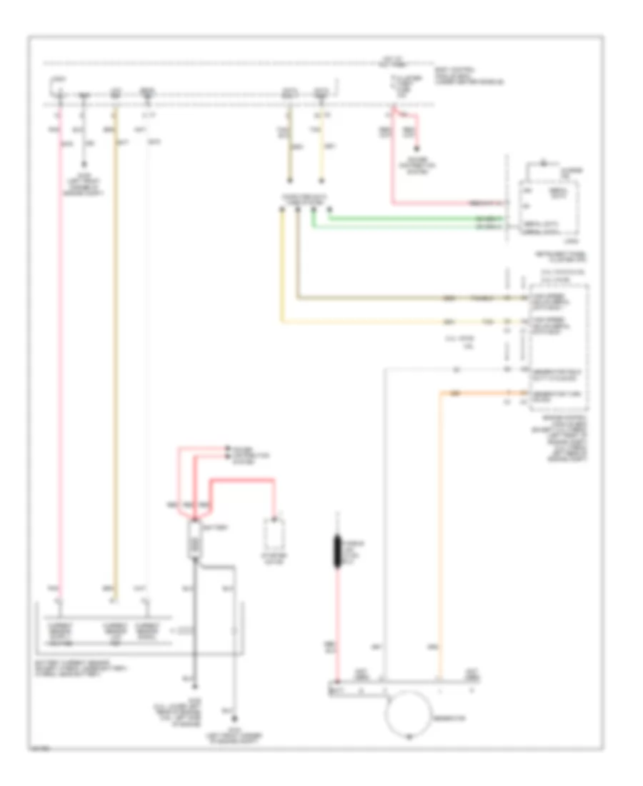
- Run/crank relay 32
- Secondary air injection (air) pump
- Secondary air injection (air) pump diode
- Secondary air injection (air) pump solenoid
- Start relay 31
- Transmission control module (tcm)
- Windshield washer fluid level switch
- Windshield washer fluid pump
- Windshield wiper motor
- Wpr 1 relay 39
- Wpr 2 relay 40
Ground Distribution Wiring Diagram (2 of 3) for Chevrolet Malibu LT 2009
List of elements for Ground Distribution Wiring Diagram (2 of 3) for Chevrolet Malibu LT 2009:
- (if equipped) adjustable pedal module
- (if equipped) audio amplifier
- (if equipped) fog lamp switch
- (if equipped) left steering wheel control switch
- (if equipped) passenger seat adjuster switch
- (if equipped) right steering wheel control switch
- (if equipped) vehicle communi- cation interface module (vcim)
- (w/ electric hybrid propulsion) generator battery disconnect control module
- (w/ power port inverter) accessory ac/dc power control module
- A x2
- A12
- Automatic a/c
- Automatic air condi- tioning
- Blower motor
- Blower motor control module
- Body control module (bcm)
- Data link connector (dlc)
- Driver door latch
- Driver door lock switch
- E12
- Fuel pump & sender assembly
- G111 (3.6l) (right rear of engine)
- G113 (3.6l) (left rear of engine)
- G201 (under center console)
- G203 (under center console)
- G301 (right "c" pillar)
- Hazard warning switch
- Horn switch
- Hvac control module
- I/p dimmer switch
- Ignition coil 1
- Ignition coil 2
- Ignition coil 3
- Ignition coil 4
- Ignition coil 5
- Ignition coil 6
- Inflatable restraint i/p module indicator
- Inflatable restraint steering wheel module coil
- Instrument panel cluster (ipc)
- J201 (behind inflatable restraint wheel module)
- Left rear door latch
- Manual a/c
- Manual air condi- tioning
- Nca
- Passenger door latch
- Passenger door lock switch
- Passenger window switch
- Radio
- Rear compartment lid release switch
- Rear window defogger grid
- Remote control door lock receiver (rcdlr)
- Right front door courtesy lamp
- Right rear door latch
- Theft deterrent module
- Traction control switch
- Turn signal/ multi-function switch
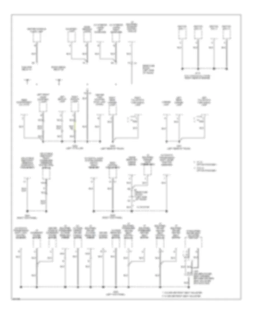
Ground Distribution Wiring Diagram (3 of 3) for Chevrolet Malibu LT 2009
List of elements for Ground Distribution Wiring Diagram (3 of 3) for Chevrolet Malibu LT 2009:
- (if equipped) driver heated seat control module
- (if equipped) driver heated seat switch
- (if equipped) driver outside rearview mirror
- (if equipped) driver seat adjuster switch
- (if equipped) garage door opener (gdo)
- (if equipped) passenger heated seat control module
- (if equipped) passenger heated seat switch
- (if equipped) passenger outside rearview mirror
- (if equipped) sunroof control module
- (w/ digital audio system s-band) digital radio receiver
- (w/ interior lamps) left sunshade
- (w/ interior lamps) right sunshade
- (w/ outside mirror) driver window motor
- Automatic transmission shift lever position indicator
- Automatic transmission shift lock control solenoid
- B x1
- Body control module (bcm)
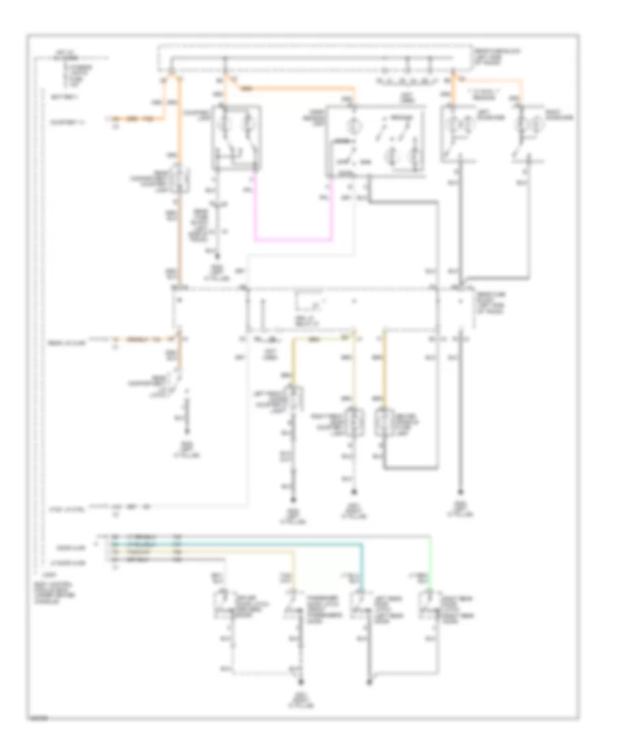
- Center console accessory power outlet
- Center console flood lamp
- Center high mounted stop lamp (chmsl)
- Courtesy lamp
- Dome/ reading lamps
- Driver window switch
- Fuel/pmp relay 37
- G110 (2.4l (vin 5) & 2.4l (vin b)) (right rear of engine)
- G302 (left "c" pillar)
- G303 (left kick panel)
- G304 (right kick panel)
- G305 (right kick panel)
- G401 (left rear of trunk)
- G403 (left rear of trunk)
- Gnd
- I/p accessory power outlet
- Ignition coil 1
- Ignition coil 2
- Ignition coil 3
- Ignition coil 4
- Inflatable restraint front passenger presence system (pps) module
- Inflatable restraint sensing & diagnostic module (sdm)
- Inside rearview mirror (isrvm)
- J302 (driver's power seat harness, between driver's seat adjuster switch & x300)
- Left backup lamp
- Left front door courtesy lamp
- Left rear marker lamp
- Left tail/stop & turn signal lamp
- License lamp
- Nca
- Outside rearview mirror switch
- R/wdo defog relay 26
- Rear compartment lid latch
- Rear fuse block (left side of trunk)
- Right backup lamp
- Right rear marker lamp
- Right tail/stop & turn signal lamp
- W/ driver front seat adjuster
- W/ lz option package-1
- W/ on star
- W/o driver front seat adjuster
- W/o lz option package-1
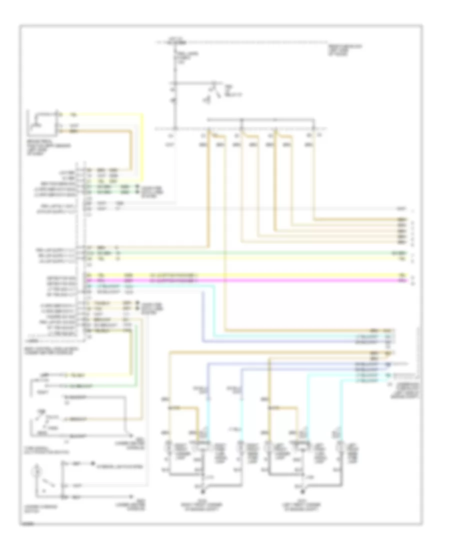
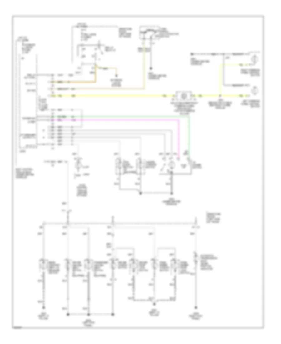
HEADLIGHTS
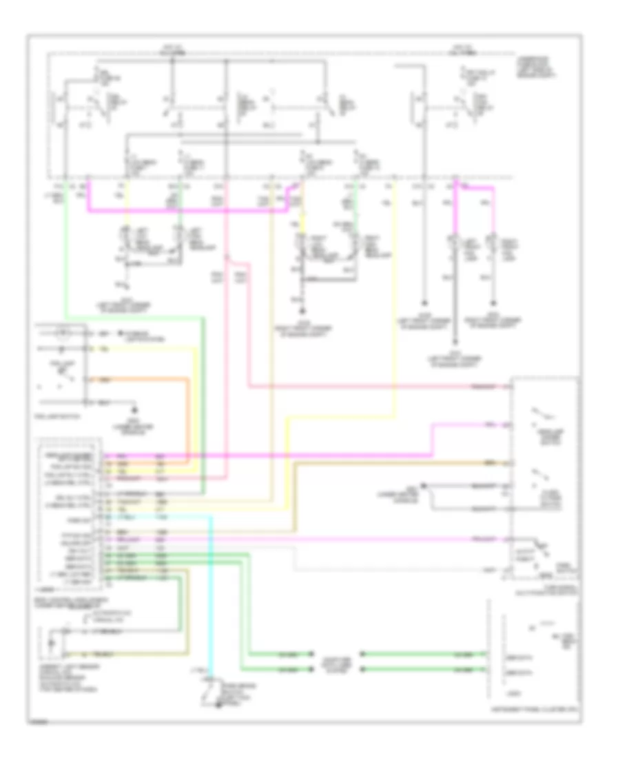
Headlights Wiring Diagram for Chevrolet Malibu LT 2009
List of elements for Headlights Wiring Diagram for Chevrolet Malibu LT 2009:
- A12
- Ambient light sensor (manual a/c) sunload sensor (automatic a/c) (top center of dash)
- Auto
- Automatic a/c
- B12
- Body control module (bcm) (under center console)
- C10
- Computer data lines system
- D10
- Drl fuse 46 15a
- Drl relay
- Drl rly ctrl
- F12
- Flash to pass switch
- Fog lamp ind
- Fog lamp switch
- Fog lmp rly ctrl
- Fog lmp sw sig
- Frt fog lp fuse 10 15a
- Frt fog relay
- Ftp sw sig
- G101 (left front corner of engine compt)
- G102 (right front corner of engine compt)
- G109 (left front corner of engine compt)
- G201 (under center console)
- G203 (under center console)
- Hdlmps off
- Head
- Headlamp dimmer sw hi bm sig
- Headlamp dimmer switch
- Hi beam rel ctrl
- Hi/ beam relay
- High beam ind
- Hot at all times
- Ign volt
- Instrument panel cluster (ipc)
- Interior lights system
- J109
- J110
- Left front fog lamp
- Left high beam headlamp
- Left low beam headlamp
- Lo beam rel ctrl
- Lo/ beam relay
- Logic
- Lt hi beam fuse 11 10a
- Lt low beam fuse 7 10a
- Lt sen low ref
- Lt sen sig
- Manual a/c
- Off
- Park
- Park brake switch (left kick panel)
- Park sw
- Park switch
- Right front fog lamp
- Right high beam headlamp
- Right low beam headlamp
- Rt hi beam fuse 12 10a
- Rt low beam fuse 9 10a
- Ser data
- Turn signal/ multi-function switch
- Underhood fuse block (left side of engine compt)
HORN
Horn Wiring Diagram for Chevrolet Malibu LT 2009
List of elements for Horn Wiring Diagram for Chevrolet Malibu LT 2009:
- (under center console) g201
- B9 x2
- Body control module (bcm) (under center console)
- E4 x3
- G101 (left front corner of engine compt)
- Horn assembly (left front of engine compt)
- Horn fuse 8 15a
- Horn relay
- Horn rly ctrl
- Horn switch
- Hot at all times
- Inflatable restraint steering wheel module coil (top of steering column)
- J201
- Logic
- Nca
- Tan
- Underhood fuse block (left side of engine compt)
- X2 k
- X3 k
INSTRUMENT CLUSTER
Instrument Cluster Wiring Diagram (1 of 2) for Chevrolet Malibu LT 2009
List of elements for Instrument Cluster Wiring Diagram (1 of 2) for Chevrolet Malibu LT 2009:
- (4 speed a/t)
- (6 speed a/t)
- Abs ind
- Acc
- Air bag ind
- Automatic transmission shift lever position ind
- Batt volt
- Body control module (bcm) (under center console)
- Brake fluid level
- Brake fluid level switch (on brake master cylinder reservoir)
- Brake ind
- Charging ind
- Chime
- Cluster/ theft fuse 10a
- Computer data lines system
- Cruise ind
- Dic sw sig
- Driver information center (dic) display
- Engine coolant temperature gauge
- Engine coolant temperature ind
- Fuel level gauge
- G109 (left front corner of engine comp)
- G201 (under center console)
- G305 (right kick panel)
- Ground
- High beam ind
- Hot at all times
- Ign 1 volt
- Ignition (run/ start)
- Ignition switch
- Illumination (4 bulbs)
- Instrument panel cluster (ipc)
- Interior lights system
- J201
- J201 (2.4l (vin 5)) (behind inflatable restraint wheel module)
- Left steering wheel control switch
- Left turn ind
- Lf dr ajar sw sig
- Logic
- Low tire pressure ind
- Malfunction ind lamp
- Mil ctrl
- Off
- Oil pressure ind
- Park brake switch
- Park brake switch (left kick panel)
- Pnk
- Power distribution system
- Right turn ind
- Run
- Seat belt ind
- Security ind
- Security ind signal
- Serial bus
- Serial data
- Speedometer
- Start
- Sw sig dr ajar
- Tachometer
- Tan
- Traction off ind
- Trip/ odometer
- Vdc ctrl ind
Instrument Cluster Wiring Diagram (2 of 2) for Chevrolet Malibu LT 2009
List of elements for Instrument Cluster Wiring Diagram (2 of 2) for Chevrolet Malibu LT 2009:
- (right "c" pillar) g301
- 2.4l (vin 5)
- 2.4l (vin b)
- 3.6l
- Ajar
- Computer data lines system
- Driver door latch (driver's door)
- Ect sens
- Engine control module (ecm) (2.4l hybrid: left rear of engine compt) (except 2.4l hybrid: left front of engine comp)
- Engine coolant temperature (ect) sensor (3.6l: left side of engine) (2.4l: lower right rear of engine)
- Engine oil pressure (eop) switch (3.6l) (lower left front of engine)
- Engine oil pressure (eop) switch (lower left rear of engine)
- Except 3.6l
- Fuel level
- Fuel pump & sender assembly (in fuel tank)
- G301 (right "c" pillar)
- Ground distribution system
- Left rear door latch (left rear door)
- Low ref
- Mil ctrl
- Oil press
- Passenger door latch (front passenger's door)
- Right rear door latch (right rear door)
- Serial data+
- Serial data-
- Tan
INTERIOR LIGHTS
Courtesy Lamps Wiring Diagram for Chevrolet Malibu LT 2009
List of elements for Courtesy Lamps Wiring Diagram for Chevrolet Malibu LT 2009:
- (left rear door)
- (not used)
- (right rear door)
- A10
- A5 x4
- Battery+
- Body control module (bcm) (under center console)
- Center console flood lamp
- Courtesy lamp
- Courtesy v+
- Ctsy lp ctrl
- D8 x1
- D9 x1
- Dome
- Dome/ reading lamp
- Door
- Door ajar
- Driver door latch (driver's ajar door)
- F2 x4
- F5 x3
- G301 (right "c" pillar)
- G302 (left "c" pillar)
- Hot at all times
- Interior lights fuse 10a
- Left front door courtesy lamp
- Left rear door latch ajar
- Left sunshade
- Lf door ajar
- Logic
- Off
- Passenger door latch (front ajar
- Passenger's door)
- Prk lp relay 27
- Reading
- Rear compartment courtesy lamp
- Rear compartment lid latch
- Rear fuse block (left side of trunk)
- Rear lid ajar
- Right front door courtesy lamp
- Right rear door latch ajar
- Right sunshade
- W/ dual reading
- X3 e3
Instrument Illumination Wiring Diagram for Chevrolet Malibu LT 2009
List of elements for Instrument Illumination Wiring Diagram for Chevrolet Malibu LT 2009:
- Automatic transmission shift lever position indicator
- B12
- Body control module (bcm) (under center console)
- C11
- C12
- D10
- Dimmer sig
- Driver door lock switch
- Driver heated seat switch (if equipped)
- Driver window switch
- E11
- Exterior lights system
- F11
- Fog lamp switch (if equipped)
- G201 (under center console)
- G203 (under center console)
- G301 (right "c" pillar)
- G303 (left kick panel)
- G305 (right kick panel)
- Gnd
- Hazard warning switch
- Head
- Hot at all times
- Hvac control module (center of dash)
- I/p dimmer switch
- I/p lp v+
- Illum
- Inflatable restraint steering wheel module coil (top of steering column)
- Interior lights fuse 10a
- J201
- J202 (behind inflatable restraint wheel module)
- Left steering wheel control switch
- Lft speaker output (+)
- Lo ref
- Logic
- Off
- Park
- Pass- enger door lock switch
- Pass- enger window switch
- Passenger heated seat switch (if equipped)
- Pk lp v+
- Prk lamps fuse 6 10a
- Prk lp relay 27
- Prk lp rly ctrl
- Rear compart- ment lid release switch
- Rear fuse block (left side of trunk)
- Right steering wheel control switch
- Str/ whl illum fuse 2a
- Sw sig
- Turn auto signal/ multi-function switch
- X1 a7
- X1 b
- X1 b1
POWER DISTRIBUTION
Power Distribution Wiring Diagram (1 of 4) for Chevrolet Malibu LT 2009
List of elements for Power Distribution Wiring Diagram (1 of 4) for Chevrolet Malibu LT 2009:
- (left side of engine compt) underhood fuse block
- (left side of trunk) rear fuse block
- (not used)
- 2.4l (vin 5)
- Abs fuse 24 60a
- Audio amp fuse 13 25a
- Audio amplifier
- Bas batt fuse 51 10a
- Battery
- Bck/up lamps fuse 17 10a
- Blower motor control module (automatic a/c)
- Body control module (bcm) (under center console)
- Bu/lp relay 33
- Center console accessory power outlet
- Cig/aux fuse 20 20a
- Digital radio receiver (w/ digital audio)
- Driver heated seat control module
- Driver seat adjuster switch
- Driver window motor (w/ power window)
- Drv seat fuse 2 30a
- Ecm fuse 13 10a
- Electronic brake control module (ebcm)
- Emission fuse 5 10a
- Engine control module (ecm)
- Evaporative emission (evap) canister vent solenoid valve
- Except 2.4l (vin 5)
- Fuel pump fuse 25 15a
- Fuel/pmp relay 37
- G303 (left kick panel)
- Garage door opener (gdo) (if equipped)
- Generator
- Generator battery assembly
- Generator battery disconnect control module
- Htd seat fuse 14 15a
- Hvac blower high relay (manual a/c)
- I/p accessory power outlet
- If equipped
- J122
- Logic
- Passenger heated seat control module
- Passenger seat adjuster switch (if equipped)
- Prk lamps fuse 6 10a
- Prk lp relay 27
- Psg seat fuse 1 30a
- Pwr wdo fuse 50 20a
- R/wdo defog relay 26
- Rbec 1 fuse 22 60a
- Rbec 2 fuse 23 60a
- Red
- Remote control door lock receiver (rcdlr)
- Rke/xm/ugdo fuse 16 7.5a
- Run relay
- Run rly fuse 19 30a
- S/roof fuse 10 15a
- Secondary air injection (air) pump relay
- Starter generator control module (scgm)
- Starter motor
- Sunroof control module (if equipped)
- To eps fuse 41 (diagram 2 of 4)
- Trunk fuse 22 10a
- Trunk relay 36
- W/ 8 way adjuster front seat
- W/ driver multi-directional adjuster front seat
- W/ enhanced audio system
- W/ fore/aft adjustment up/down front seat
- W/ power reduced effort
- X1 a5
- X3 d10
- X4 e2
Power Distribution Wiring Diagram (2 of 4) for Chevrolet Malibu LT 2009
List of elements for Power Distribution Wiring Diagram (2 of 4) for Chevrolet Malibu LT 2009:
- (2.4l (vin b))
- (automatic a/c) (manual a/c)
- (left side of engine compt) underhood fuse block
- (not used)
- 3.6l
- 4 speed a/t
- 6 speed a/t
- Acc
- Air bag (batt) fuse 10a
- Air pump fuse 52 30a
- Air pump relay 53 (2.4l (vin b))
- Automatic transmission
- Batt sense fuse 54 5a
- Body control module (bcm)
- Body control module (bcm) (under center console)
- Cluster/ theft fuse 10a
- Cool fan 1 fuse 17 30a
- Cool fan 2 fuse 18 30a
- Cool/fan 1 relay 28
- Cool/fan 2 relay 30
- Cool/fan ser/par relay 29
- D11
- D12
- Data link connector (dlc)
- Electric power steering module (w/o power steering)
- Eps fuse 41 80a
- From abs a
- Fuse 24 (diagram 1 of 4)
- Hi/beam relay 35
- Hvac control module
- Hvac ctrl (batt) fuse 10a
- Ibcm 1 fuse 20 30a
- Ign 1 vlt
- Ign sensor fuse 2a
- Ignition switch
- Inflatable restraint sensing & diagnostic module (sdm)
- Instrument panel cluster (ipc)
- Key in ignition switch
- Lo/beam relay 38
- Logic
- Off
- Pnk
- Radio
- Radio fuse 10a
- Run
- Start
- Tcm fuse 42 10a
- Theft deterrent module (tdm)
- To strtr fuse 26 (diagram 3 of 4)
- Trans pmp mtr relay 53 (2.4l (vin 5))
- Trans pump mtr fuse 52 20a
- Transmission control module (tcm)
- X1 b
- X2 off/run/crank
Power Distribution Wiring Diagram (3 of 4) for Chevrolet Malibu LT 2009
List of elements for Power Distribution Wiring Diagram (3 of 4) for Chevrolet Malibu LT 2009:
- (in driver heated seat harness, 5 cm from main branch) j301
- (left side of engine compt) underhood fuse block
- (not used)
- (right "c" pillar) g301
- 110 v ac
- 110 v accessory power outlet (if equipped)
- A/c clu fuse 1 10a
- A/c clutch relay 34
- Accessory ac/dc power control module (w/ power port inverter) (right rear of trunk)
- Accessory relay
- Adjustable pedal module (if equipped)
- Adjustable pedal position switch (if equipped)
- Batt abs fuse 56 30a
- Body control module (bcm) (under center console)
- D10
- Dc/ac inv fuse 55 30a
- Door lock fuse 15a
- Driver heated seat control module
- Driver heated seat switch
- Driver window motor (w/ power windows)
- Driver window switch
- Drl fuse 46 15a
- Drl relay 48
- E10
- Electronic brake control module (ebcm) (except 2.4l (vin 5))
- From b cool fan 2 fuse 18 (diagram 2 of 4)
- From underhood fuse block (diagram 3 of 4)
- Frt fog lp fuse 10 15a
- Frt fog relay 36
- Horn fuse 8 15a
- Horn relay 37
- Ibcm 2 fuse 25 50a
- Inside rearview mirror (isvrm)
- Interior lights fuse 10a
- Logic
- Onstar fuse 10a
- Outside rearview mirror switch
- Passenger heated seat control module
- Passenger heated seat switch
- Passenger window switch
- Pedal fuse 10a
- Power mirrors fuse 2a
- Power windows fuse 30a
- Pwr/trn relay 33
- Rear fuse block (left side of trunk)
- Roof/heat seat fuse 10a
- Start relay 31
- Stop lp fuse 47 10a
- Stop lp relay 49
- Strtr fuse 26 30a
- Sunroof control module (if equipped)
- To accessory ac/dc power control module (diagram 3 of 4)
- To run/crank relay 32 (diagram 4 of 4)
- Vehicle communication interface module (vcim) (if equipped)
- W/ front heated seats
- W/ vehicle communication system
- Windshield wiper/ washer switch
- Wiper diode
- Wiper sw fuse 10a
- Wpr 1 relay 39
- Wpr 2 relay 40
- Wpr fuse 14 25a
Power Distribution Wiring Diagram (4 of 4) for Chevrolet Malibu LT 2009
List of elements for Power Distribution Wiring Diagram (4 of 4) for Chevrolet Malibu LT 2009:
- (2.4l (vin 5)) (3.6l)
- (behind inflatable restraint wheel module) j209
- (engine harness, 100 mm from inline to transmission breakout) j103
- (left side of engine compt) underhood fuse block
- (not used)
- 1-2 shift solenoid (ss) valve
- 2-3 shift solenoid (ss) valve
- 2.4 (vin 5)
- 2.4l (vin 5)
- 2.4l (vin 5) a/t
- 3.6l
- 3.6l 2.4l (vin b)
- 4 speed a/t
- 4-3 shift solenoid (ss) valve
- 6 speed a/t
- Abs fuse 15 10a
- Air bag (ign) fuse 10a
- Automatic transmission
- B10
- Bas ign fuse 3 10a
- Body control module (bcm) (under center console)
- C10
- Ecm ign fuse 16 10a
- Electric power steering (eps) module (w/o power steering)
- Electronic brake control module (ebcm)
- Engine control module (ecm)
- Eps fuse 2a
- Except (2.4l (vin 5))
- From horn fuse 8 (diagram 3 of 4)
- G109 (left front corner of engine compt)
- Generator battery assembly
- Generator battery disconnect control module
- Heater coolant pump
- Ibcm (run/crank) fuse 21 30a
- Inflatable restraint front passenger presence system (pps) module
- Inflatable restraint i/p module indicator
- Inflatable restraint sensing & diagnostic module (sdm)
- Inflatable restraint steering wheel module coil
- Left automatic transmission manual shift switch
- Left steering wheel control switch
- Logic
- Maf (3.6l) bas pmps (2.4l (vin 5)) fuse 5 20a 10a
- Manual shift
- Mass air flow (maf)/ intake air temperature (iat) sensor
- Pnk
- Red
- Run/ crank fuse 2a
- Run/crank relay 32
- Starter generator control module (scgm)
- Starter generator control module (scgm) coolant pump
- Torque converter clutch (tcc) pulse width modulation (pwm) solenoid valve
- Trans fuse 4 10a
- Transmission control module (tcm)
- W/ a/t
- W/ steering wheel control
- W/o a/t
- X100
- X2 e
POWER DOOR LOCKS
Power Door Locks Wiring Diagram for Chevrolet Malibu LT 2009
List of elements for Power Door Locks Wiring Diagram for Chevrolet Malibu LT 2009:
- Ajar
- Body control module (bcm) (under center console)
- Computer data lines system
- Ctrl actr unlk dr lk
- Ctrl actr unlk drv dr lk
- Door lock fuse 15a
- Dr lk actr lk ctrl
- Dr lk lk/unlk sig
- Driver door latch (driver's door)
- Driver door lock switch
- Driver information center (dic)
- G301 (right "c" pillar)
- Gmlan serial data
- Ground
- Hot at all times
- Instrument panel cluster (ipc)
- Interior lights system
- Key sw sig drv dr
- Left rear door latch (left rear door)
- Lf dr ajar sw sig
- Lock
- Logic
- Low spd
- Low spd gmlan serial data
- Passenger door latch (front passenger's door)
- Passenger door lock switch
- Power distribution system
- Rear fuse block (left side of trunk)
- Remote control door lock receiver (rcdlr) (under center of rear window shelf)
- Right rear door latch (right rear door)
- Rke/xm/ ugdo fuse 16 7.5a
- Serial data
- Sw sig dr ajar
- Tan
- Trunk release rly ctrl
- Trunk, tailgate, fuel doors system
- Unlock
- Unlock relay
- Vehicle communications interface module (vcim) (right side of dash)
- W/ on star
- W/o driver door
- W/o on star
POWER MIRRORS
Automatic Day/Night Mirror Wiring Diagram for Chevrolet Malibu LT 2009
List of elements for Automatic Day/Night Mirror Wiring Diagram for Chevrolet Malibu LT 2009:
- (right kick panel) g305
- Acc voltage
- Ambient light sensor (windshield side)
- Bck/up lamps fuse 17 10a
- Body control module (bcm) (under center console)
- Bu/lp relay 33
- Button back lighting
- Day/night mirror signal
- Driver outside rearview mirror (if equipped)
- Emergency ind
- Emergency switch
- Exterior lights system
- Ground
- Headlight sensor (mirror side)
- Hot at all times
- Hot w/ accessory relay energized
- Inside rearview mirror (isrvm)
- Keypad green led ind
- Keypad green led signal
- Keypad red led ind
- Keypad red led signal
- Keypad signal
- Logic
- Low ref
- Nca
- Onstar button assembly
- Onstar ind
- Onstar switch
- Phone ind
- Phone switch
- Pnk
- Power tops system
- Power windows system
- Rear fuse block (left side of trunk)
- Resets to daytime high reflectivity in reverse
- Rev lmp rly ctrl
- Roof/heat seat fuse 10a
- Vehicle communication interface module (vcim) (if equipped) (right side of dash)
Power Mirrors Wiring Diagram for Chevrolet Malibu LT 2009
List of elements for Power Mirrors Wiring Diagram for Chevrolet Malibu LT 2009:
- Body control module (bcm) (under center console)
- Defogger system
- Down
- Driver outside rearview mirror
- G303 (left kick panel)
- Hot at all times
- J501
- Left
- Left/ right
- Nca
- Outside rearview mirror switch
- Passenger outside rearview mirror
- Power mirrors fuse 2a
- Right
- Up/ down
POWER SEATS
2-Way Adjustable Power Seat Wiring Diagram for Chevrolet Malibu LT 2009
List of elements for 2-Way Adjustable Power Seat Wiring Diagram for Chevrolet Malibu LT 2009:
- Down
- Driver seat adjuster switch
- Driver seat vertical motor (under driver's seat)
- Drv seat fuse 2 30a
- G303 (left kick panel)
- Hot at all times
- J302
- Rear fuse block (left side of trunk)
6-Way Power Seat Wiring Diagram for Chevrolet Malibu LT 2009
List of elements for 6-Way Power Seat Wiring Diagram for Chevrolet Malibu LT 2009:
- Driver seat adjuster switch
- Driver seat front vertical motor (under driver's seat)
- Driver seat horizontal motor (under driver's seat)
- Driver seat rear vertical motor (driver's seat back)
- Drv seat fuse 2 30a
- Front down
- Front up
- Fwd
- G303 (in left kick panel)
- Hot at all times
- Rear down
- Rear fuse block (left side of trunk)
- Rear up
- Rwd
- Tan
8-Way Adjustable Power Seat Wiring Diagram for Chevrolet Malibu LT 2009
List of elements for 8-Way Adjustable Power Seat Wiring Diagram for Chevrolet Malibu LT 2009:
- Down
- Driver seat adjuster switch
- Driver seat front vertical motor (under driver's seat)
- Driver seat horizontal motor (under driver's seat)
- Driver seat rear vertical motor (driver's seat back)
- Driver seat recline motor (driver's seat back)
- Drv seat fuse 2 30a
- Front down
- Front up
- Fwd
- G303 (left kick panel)
- Hot at all times
- Rear down
- Rear fuse block (left side of trunk)
- Rear up
- Recline
- Rwd
- Tan
Adjustable Pedal Wiring Diagram for Chevrolet Malibu LT 2009
List of elements for Adjustable Pedal Wiring Diagram for Chevrolet Malibu LT 2009:
- Adj pedal inhibit sw
- Adjustable pedal actuator (left side of dash)
- Adjustable pedal module (left side of dash)
- Adjustable pedal position sensor (left side of dash)
- Adjustable pedal position switch
- Battery
- Body control module (bcm) (under center console)
- D10
- Enable sig
- Fwd
- G201 (under center console)
- Gnd
- Hot at all times
- Inhibit sig
- Logic
- Low ref
- Pedal fuse 10a
- Pnk
- Rwd
- Sens sig
Heated Seats Wiring Diagram for Chevrolet Malibu LT 2009
List of elements for Heated Seats Wiring Diagram for Chevrolet Malibu LT 2009:
- (left kick panel) g303
- Accy vlt
- Accy voltage
- Battery positive
- Battery positive voltage
- Body control module (bcm) (under center console)
- Driver back heated seat element (driver's seat back)
- Driver heated seat control module (under driver's seat)
- Driver heated seat cushion element
- Driver heated seat switch
- G303 (left kick panel)
- Gnd
- Ground
- Heated seat sw sig
- High
- Hot at all times
- Hot w/ accessory relay energized
- Htd seat fuse 14 15a
- Illum
- Interior lights system
- J301
- Logic
- Low
- Passenger back heated seat element (front passenger's seat back)
- Passenger heated seat control module (under front passenger's seat)
- Passenger heated seat cushion element
- Passenger heated seat switch
- Rear fuse block (left side of trunk)
- Red
- Roof/ heat seat fuse 10a
- Seat back element ctrl
- Seat back element voltage
- Seat cushion element ctrl
- Seat cushion element voltage
- Seat cushion temp sen low ref
- Seat cushion temp sen sig
Passenger Power Seat Wiring Diagram for Chevrolet Malibu LT 2009
List of elements for Passenger Power Seat Wiring Diagram for Chevrolet Malibu LT 2009:
- Front down
- Front up
- Fwd
- G301 (right "c" pillar)
- Hot at all times
- Passenger seat adjuster switch
- Passenger seat front vertical motor (under front passenger's seat)
- Passenger seat horizontal motor (under front passenger's seat)
- Passenger seat rear vertical motor (under front passenger's seat)
- Psg seat fuse 1 30a
- Rear down
- Rear fuse block (left side of trunk)
- Rear up
- Rwd
- Tan
POWER TOP/SUNROOF
Power Top/Sunroof Wiring Diagram for Chevrolet Malibu LT 2009
List of elements for Power Top/Sunroof Wiring Diagram for Chevrolet Malibu LT 2009:
- (center rear of sunroof) sunroof motor
- Accessory voltage
- Battery positive voltage
- Body control module (bcm) (under center console)
- Close
- G302 (left "c" pillar)
- Ground
- Hot at all times
- Hot w/ accessory relay energized
- Open
- Power distribution system
- Rear fuse block (left side of trunk)
- Roof/heat seat fuse 10a
- S/roof fuse 10 15a
- Sunroof control module (center rear of sunroof)
- Sunroof switch
- Sunroof switch close signal
- Sunroof switch low reference
- Sunroof switch open signal
- X4 f2
POWER WINDOWS
Power Windows Wiring Diagram for Chevrolet Malibu LT 2009
List of elements for Power Windows Wiring Diagram for Chevrolet Malibu LT 2009:
- (in left front door) left front window motor
- A11
- B11
- Body control module (bcm) (under center console)
- C11
- Down
- Driver
- Driver window switch
- Express down
- Express logic
- Express up
- G301 (right "c" pillar)
- G303 (left kick panel)
- Hot at all times
- Hot w/ accessory relay energized
- Illum
- Illumination
- Interior lights system
- Left front window motor (in left front door)
- Left rear
- Left rear window motor (in left rear door)
- Left rear window switch
- Logic
- Passenger
- Passenger window switch
- Power distribution system
- Power windows fuse 30a
- Pwr wdo fuse 50 20a
- Right front window motor (in right front door)
- Right rear
- Right rear window motor (in right rear door)
- Right rear window switch
- Roof/ heat seat fuse 10a
- Tan
- Underhood fuse block (left side of of engine compt)
- W/ express driver up/down
- W/o express driver up/down
- Window lock out switch
RADIO
Radio Wiring Diagram, Enhanced (1 of 3) for Chevrolet Malibu LT 2009
List of elements for Radio Wiring Diagram, Enhanced (1 of 3) for Chevrolet Malibu LT 2009:
- 10-volt ref
- 12v
- Amplifier mute
- Ant 12-volt switched sply volt
- Antenna signal
- Bare
- Battery positive volt
- Body control module (bcm) (under center console)
- Cellular telephone voice low ref
- Cellular telephone voice sig
- Coax
- Computer data lines system
- Drain wire
- G201 (under center console)
- Gnd
- Hot at all times
- I/p lamp sply volt
- Interior lights system
- Lf low level audio signal (+)
- Lf low level audio signal (-)
- Lh audio signal (+)
- Lo spd gmlan serial data
- Logic
- Low ref
- Lr low level audio signal (+)
- Lr low level audio signal (-)
- Pnk
- Radio
- Radio antenna
- Radio antenna module (right rear of roof)
- Radio fuse 10a
- Rear window radio antenna
- Remote radio audio output (-)
- Rf low level audio signal (+)
- Rf low level audio signal (-)
- Rh audio signal (+)
- Rr low level audio signal (+)
- Rr low level audio signal (-)
- Satellite radio circuit
- Steering wheel controls sig
- Tan
- Vehicle communication interface module (w/ onstar) (right side of dash)
- Voice sig
Radio Wiring Diagram, Enhanced (2 of 3) for Chevrolet Malibu LT 2009
List of elements for Radio Wiring Diagram, Enhanced (2 of 3) for Chevrolet Malibu LT 2009:
- 1-6
- Inflatable restraint steering wheel module coil (top of steering column)
- Left front door speaker
- Left front tweeter speaker
- Nca
- Pnk
- Right front door speaker
- Right front tweeter speaker
- Right steering wheel control switch
- Seek dn
- Seek up
- Tan
- Vol dn
- Vol up
- X2 c
- X3 c
Radio Wiring Diagram, Enhanced (3 of 3) for Chevrolet Malibu LT 2009
List of elements for Radio Wiring Diagram, Enhanced (3 of 3) for Chevrolet Malibu LT 2009:
- Amplifier mute
- Ant 12-volt switched sply volt
- Audio amp fuse 13 25a
- Audio amplifier (right rear of trunk)
- Battery positive voltage
- Ef low level audio signal (-)
- G301 (right "c" pillar)
- Ground
- Hot at all times
- Left rear speaker
- Lf low level audio signal (+)
- Lf low level audio signal (-)
- Lf speaker output (+)
- Lf speaker output (-)
- Lr low level audio signal (+)
- Lr low level audio signal (-)
- Lr speaker output (+)
- Lr speaker output (-)
- Lr subwoofer speaker out (+)
- Lr subwoofer speaker out (-)
- Pnk
- Rear fuse block (left side of trunk)
- Rf low level audio signal (+)
- Rf speaker output (+)
- Rf speaker output (-)
- Right rear speaker
- Rr low level audio signal (+)
- Rr low level audio signal (-)
- Rr speaker output (+)
- Rr speaker output (-)
- Tan
Radio Wiring Diagram, Premium (1 of 2) for Chevrolet Malibu LT 2009
List of elements for Radio Wiring Diagram, Premium (1 of 2) for Chevrolet Malibu LT 2009:
- 10-volt ref
- 12v
- Ant 12-volt switched sply volt
- Antenna signal
- Bare
- Battery positive volt
- Body control module (bcm) (under center console)
- Cellular telephone voice low ref
- Cellular telephone voice signal
- Coax
- Computer data lines system
- Drain wire
- G201 (under center console)
- Ground
- Hot at all times
- I/p lamp sply volt
- Interior lights system
- Lf speaker output (+)
- Lf speaker output (-)
- Lh audio signal (+)
- Lo spd gmlan serial data
- Logic
- Low ref
- Lr speaker output (+)
- Lr speaker output (-)
- Pnk
- Radio
- Radio antenna
- Radio antenna module (right rear of roof)
- Radio fuse 10a
- Rear window radio antenna
- Remote radio audio output (-)
- Rf speaker output (+)
- Rf speaker output (-)
- Rh audio signal (+)
- Rr speaker output (+)
- Rr speaker output (-)
- Satellite radio circuit
- Steering wheel controls signal
- Tan
- Vehicle communication interface module (w/ onstar) (right side of dash)
- Voice sig
Radio Wiring Diagram, Premium (2 of 2) for Chevrolet Malibu LT 2009
List of elements for Radio Wiring Diagram, Premium (2 of 2) for Chevrolet Malibu LT 2009:
- 1-6
- B tan
- C x3
- Inflatable restraint steering wheel module coil (top of steering column)
- Left front door speaker
- Left front tweeter speaker
- Left rear speaker
- Nca
- Right front door speaker
- Right front tweeter speaker
- Right rear speaker
- Right steering wheel control switch
- Seek dn
- Seek up
- Tan
- Vol dn
- Vol up
- X2 c
Satellite Radio Wiring Diagram for Chevrolet Malibu LT 2009
List of elements for Satellite Radio Wiring Diagram for Chevrolet Malibu LT 2009:
- Antenna sig
- Audio out -
- Bare
- Battery
- Cellular & digital radio antenna (center rear of roof)
- Coax
- Computer data lines system
- Digital radio receiver (under center of rear package shelf)
- Drain wire
- G305 (right kick panel)
- Ground
- Hot at all times
- Lh audio sig +
- Lo spd gmlan serial data
- Power distribution system
- Radio
- Rear fuse block (left side of trunk)
- Rh audio sig +
- Rke/xm/ ugdo fuse 16 7.5a
- Serial data
SHIFT INTERLOCK
Shift Interlock Wiring Diagram for Chevrolet Malibu LT 2009
List of elements for Shift Interlock Wiring Diagram for Chevrolet Malibu LT 2009:
- 2.4l (vin 5) & 3.6l (vin 7)
- 2.4l (vin b)
- 3.6l (vin 7)
- 4-speed a/t
- 5 volt reference
- 6-speed
- A/t internal mode (ims) switch
- Automatic transmission
- Automatic transmission shift lock control solenoid (on floor shifter)
- Battery
- Body control module (bcm) (under center console)
- Brake pedal position (bpp) sensor (left side of dash)
- Brake pedal position sensor signal
- Computer data lines system
- Control solenoid valve assembly
- Door lock fuse 15a
- Engine control module (ecm) (2.4l, 3.6l: left front of engine compt) (2.4l hybrid: left rear of engine compt)
- G107 (2.4l: lower left side of engine) (3.6l: center rear of engine)
- G303 (left kick panel)
- G305 (right kick panel)
- Ground
- Hot at all times
- Ign lk ctrl sig prk/neutral
- Interior lights fuse 10a
- Logic
- Low reference
- P/n
- Park/neutral position (pnp) switch (on automatic transmission)
- Srl data (+)
- Srl data (-)
- Tan
STARTING/CHARGING
Charging Wiring Diagram for Chevrolet Malibu LT 2009
List of elements for Charging Wiring Diagram for Chevrolet Malibu LT 2009:
- (not used)
- 2.4l (vin 5) & 3.6l
- 2.4l (vin b)
- 3.6l
- Batt
- Battery
- Battery current sensor (except hybrid: under battery) (hybrid: near battery)
- Body control module (bcm) (under center console)
- Charge ind
- Cluster/ theft fuse 10a
- Computer data lines system
- Current sensor low ref
- Current sensor signal
- Data bus +
- Data bus -
- Engine control module (ecm) (except 2.4l hybrid: (left front of engine compt) (2.4l hybrid: left rear of engine compt)
- G104 (left front corner of engine compt)
- G105 (2.4l: lower left rear of engine) (3.6l: left side of engine)
- G109 (left front corner of engine compt)
- Generator
- Generator field duty cycle sig
- Generator turn on sig
- Gnd
- High speed gmlan serial data bus +
- High speed gmlan serial data bus -
- Hot at all times
- Ign
- Instrument panel cluster (ipc)
- Logic
- Low ref
- Pnk
- Power distribution system
- Red
- Sens sig
- Serial data
- Starter motor
- Tan
- Volt
Starting Wiring Diagram for Chevrolet Malibu LT 2009
List of elements for Starting Wiring Diagram for Chevrolet Malibu LT 2009:
- (2.4l: lower left side of engine) (3.6l: center rear of engine) g107
- (left side of engine compt)
- (lower left side of engine) g107
- (under center console)
- 2.4l (vin 5) & 3.6l
- 2.4l (vin b)
- 2.4l (vin b) & 3.6l
- 3.6l
- 4 speed a/t
- 6 speed a/t
- Acc
- Automatic transmission
- Automatic transmission internal mode switch (ims)
- Battery
- Body control module (bcm)
- C1 x2
- C10
- Computer data lines system
- Control solenoid valve assembly
- D1 x4
- D12 x1
- Engine control module (ecm) (except 2.4l hybrid: left front of engine compt) (2.4l hybrid: left rear of engine compt)
- G104 (left front corner of engine compt)
- G105 (2.4l: lower left rear of engine) (3.6l: left side of engine)
- G109 (left front corner of engine compt)
- Generator
- High speed gmlan serial data bus +
- High speed gmlan serial data bus -
- Hot at all times
- Ign key resistor signal
- Ign sensor fuse 2a
- Ignition 1
- Ignition switch
- Key in ignition switch
- Logic
- Off
- Off/run/ crank voltage
- Park/neutral position (pnp) switch (on automatic transmission)
- Park/neutral sig
- Pnk
- Power distribution system
- Red
- Run
- Start
- Start relay 31
- Starter motor
- Starter rly coil ctrl
- Strtr fuse 26 30a
- Tan
- Transmission control module (tcm)
- Underhood fuse block
SUPPLEMENTAL RESTRAINTS
Supplemental Restraints Wiring Diagram (1 of 3) for Chevrolet Malibu LT 2009
List of elements for Supplemental Restraints Wiring Diagram (1 of 3) for Chevrolet Malibu LT 2009:
- (or pnk)
- (right kick panel) g304 computer data lines system
- Air bag (batt) fuse 10a
- Air bag (ign) fuse 10a
- Body control module (bcm) (under center console)
- Case ground
- D11
- Driver seat belt pretensioner (base of left "b" pillar)
- Driver seat belt switch (integral to driver's seat belt buckle assembly)
- Ground
- High control
- Hot at all times
- Hot w/ run/crank relay energised
- Ignition 1
- Inflatable restraint sensing & diagnostic module (sdm) (under center console)
- Left front inflatable restraint roof rail module (if equipped) (rear of left roof rail)
- Left inflatable restraint front end sensor (left front of engine compt)
- Left inflatable restraint side impact sensor (sis) (if equipped) (driver's door)
- Low control
- Low ref
- Occupant sens
- Passenger seat belt pretensioner (base of right "b" pillar)
- Passenger seat belt switch (integral to front passenger's seat belt buckle assembly)
- Pnk
- Right front inflatable restraint roof rail module (if equipped) (rear of right roof rail)
- Right inflatable restraint front end sensor (right front of engine compt)
- Right inflatable restraint side impact sensor (sis) (if equipped) (in passenger's door)
- Serial data
- Shorting bar
- Signal
- Tan
- Voltage
Supplemental Restraints Wiring Diagram (2 of 3) for Chevrolet Malibu LT 2009
List of elements for Supplemental Restraints Wiring Diagram (2 of 3) for Chevrolet Malibu LT 2009:
- Air bag indicator
- Batt
- Body control module (bcm) (under center console)
- Computer data lines system
- Inflatable restraint i/p module (right side of dash)
- Inflatable restraint steering wheel module (in steering wheel)
- Inflatable restraint steering wheel module coil (top of steering column)
- Instrument panel cluster
- Left inflatable restraint side impact module (if equipped) (left side of driver's seat back)
- Logic
- Pnk
- Right inflatable restraint side impact module (if equipped) (right side of front passenger's seat back)
- Seat belt indicator
- Serial data
- Shorting bar
- Stage 1
- Stage 2
- Tan
- Vehicle communications interface module (right side of dash)
- W/ vehicle communications
- W/o vehicle communications
Supplemental Restraints Wiring Diagram (3 of 3) for Chevrolet Malibu LT 2009
List of elements for Supplemental Restraints Wiring Diagram (3 of 3) for Chevrolet Malibu LT 2009:
- (right kick panel) g304
- Body control module (bcm) (under center console)
- Case ground
- G203 (under center console)
- Ground
- Hot w/ run/crank relay energized
- Ign 1 volt
- Illum
- Inflatable restraint front passenger presence system (pps) module (in front passenger's seat cushion)
- Inflatable restraint i/p module indicator
- Logic
- Off ind
- On ind
- Pass seat belt ind
- Pnk
- Power
- Run/ crank fuse 2a
- Serial data
TRANSMISSION
2.4L VIN 5
2.4L VIN 5, Transmission Wiring Diagram (1 of 2) for Chevrolet Malibu LT 2009
List of elements for 2.4L VIN 5, Transmission Wiring Diagram (1 of 2) for Chevrolet Malibu LT 2009:
- 1-2 shift solenoid valve
- 1-2 ss vlv ctrl
- 2-3 shift solenoid valve
- 2-3 ss vlv ctrl
- 4-3 shift solenoid valve
- Acc
- Acc volt
- Acc voltage
- At iss high sig
- At iss low sig
- Automatic transmission
- Automatic transmission output shaft speed (oss) sensor (in automatic transmission)
- B(+)
- Body control module (bcm) (under center console)
- Computer data lines system
- Exterior lights system
- G107 (lower left side of engine)
- Gmlan bus (+)
- Gmlan bus (-)
- Gnd
- Hot at all times
- Ign 1 voltage
- Ignition switch
- J103
- J201
- Logic
- Low reference
- Off
- Pc sol hi ctrl
- Pc sol val low ctrl
- Pnk
- Red
- Run
- Sol vlv high ctrl
- Start
- Stop lmp sw sig
- Tan
- Tcc pwm vlv ctrl
- Tcc release sw sig
- Tfp switch signal
- Tft sens sig
- Torque converter clutch (tcc) pulse width modulation (pwm) solenoid valve
- Trans fluid press
- Trans sw sig a
- Trans sw sig c
- Trans sw sig p
- Trans switch sig b
- Transmission control module (tcm) (left side of engine compt)
- Vss high sig
- Vss low sig
2.4L VIN 5, Transmission Wiring Diagram (2 of 2) for Chevrolet Malibu LT 2009
List of elements for 2.4L VIN 5, Transmission Wiring Diagram (2 of 2) for Chevrolet Malibu LT 2009:
- (tft) sensor
- A12
- Automatic transmission
- Automatic transmission auxiliary fluid pump
- Automatic transmission auxiliary fluid pump control module
- Automatic transmission fluid pressure (tfp) manual valve position switch
- Automatic transmission fluid temperature
- Automatic transmission input shaft speed (iss) sensor
- C12
- Energized
- Engine control module (ecm) (left rear of engine compartment)
- G107 (lower left side of engine)
- Generator turn signal
- Hot at all times
- Hot w/ run/crank relay 32
- Park/neutral position (pnp) switch (on automatic transmission)
- Pnk
- Pressure control (pc) solenoid valve
- Pump rly coil ctrl
- Red
- Starter generator control module (sgcm) (left front of engine compartment)
- Tan
- Tcm fuse 42 10a
- Trans fluid press switch signal a
- Trans fuse 4 10a
- Trans pmp mtr fuse 52 20a
- Trans pmp mtr relay 53
- Underhood fuse block (left side of engine compartment)
- Volt ref
2.4L VIN B
2.4L VIN B, Transmission Wiring Diagram, 4 Speed A/T for Chevrolet Malibu LT 2009
List of elements for 2.4L VIN B, Transmission Wiring Diagram, 4 Speed A/T for Chevrolet Malibu LT 2009:
- (tfp) sw sig c
- (tft) sensor
- 1-2 shift solenoid valve
- 1-2 ss vlv ctrl
- 2-3 shift solenoid valve
- 2-3 ss vlv ctrl
- Acc
- Acc volt
- Acc voltage
- At iss high sig
- At iss low sig
- Automatic transmission
- Automatic transmission fluid pressure (tfp) manual valve position switch
- Automatic transmission fluid temperature
- Automatic transmission input shaft speed (iss) sensor
- Automatic transmission output shaft speed (oss) sensor
- B(+)
- Body control module (bcm) (under center console)
- Computer data lines system
- Energized
- Engine control module (ecm) (left front of engine compartment)
- Exterior lights system
- G107 (lower left side of engine)
- Gmlan bus (+)
- Gmlan bus (-)
- Gnd
- Hot at all times
- Hot w/ run/crank relay 32
- Ign 1 voltage
- Ignition switch
- J103
- Logic
- Low reference
- Off
- Park/neutral position (pnp) switch (on automatic transmission)
- Pc sol hi ctrl
- Pc sol val low ctrl
- Pnk
- Pressure control (pc) solenoid valve
- Red
- Run
- Start
- Stop lmp sw sig
- Tan
- Tcc pwm vlv ctrl
- Tcc release sw sig
- Tcm fuse 42 10a
- Tfp switch signal b
- Tft sens sig
- Torque converter clutch (tcc) pulse width modulation (pwm) solenoid valve
- Trans fuse 4 10a
- Trans sw sig a
- Trans sw sig c
- Trans sw sig p
- Trans switch sig b
- Transmission control module (lower left front of engine compartment)
- Underhood fuse block (left side of engine compartment)
- Vss high sig
- Vss low sig
2.4L VIN B, Transmission Wiring Diagram, 6 Speed A/T (1 of 2) for Chevrolet Malibu LT 2009
List of elements for 2.4L VIN B, Transmission Wiring Diagram, 6 Speed A/T (1 of 2) for Chevrolet Malibu LT 2009:
- 1-2 shift solenoid (ss) valve
- 2-3 shift solenoid (ss) valve
- Automatic transmission
- Automatic transmission fluid temperature (tft) sensor
- Automatic transmission internal mode switch (ims)
- Computer data lines system
- Control (pc) solenoid valve
- Control solenoid valve assembly
- Cruise control system
- E pnk
- F10
- G107 (lower left side of engine)
- Gmlan data bus+
- Gmlan data bus-
- Ground
- Ign
- Inflatable restraint steering wheel module coil (top of steering wheel)
- J209 (behind inflatable restraint wheel module)
- Left automatic transmission manual shift switch
- Low ref
- Pc 1 solenoid
- Pc 2 solenoid
- Pc 3 solenoid
- Pc 4 solenoid
- Pc 5 solenoid
- Pnk
- Pressure control (pc) solenoid valve 1
- Pressure control (pc) solenoid valve 2
- Pressure control (pc) solenoid valve 3
- Pressure control (pc) solenoid valve 4
- Pressure control (pc) solenoid valve 5
- Red
- Ss 1
- Ss 2
- Start
- Stop lamp sw
- Tan
- Tap up/tap dn sw
- Tccpc solenoid
- Tft
- Torque converter clutch (tcc) pressure
- Transmission control module (tcm)
- Transmission range sig a
- Transmission range sig b
- Transmission range sig c
- Transmission range sig p
- Underhood fuse block (left side of engine compt)
2.4L VIN B, Transmission Wiring Diagram, 6 Speed A/T (2 of 2) for Chevrolet Malibu LT 2009
List of elements for 2.4L VIN B, Transmission Wiring Diagram, 6 Speed A/T (2 of 2) for Chevrolet Malibu LT 2009:
- Acc
- Acc volt
- Automatic transmission
- Automatic transmission fluid pressure (tfp) manual valve position switch
- Automatic transmission input shaft speed sensor (iss)
- Automatic transmission output shaft speed sensor (oss)
- Body control module (bcm) (under center console)
- C9 pnk
- Computer data lines system
- Control solenoid valve assembly
- Data bus-
- Driver information center (dic) display
- Engine control module (ecm) (left front of engine compartment)
- Gmlan bus (+)
- Gmlan bus (-)
- Gmlan serial
- Hot at all times
- Hot in run or start
- Hot w/ run/crank relay 32 energized
- Ign
- Ignition switch
- Instrument panel cluster (ipc)
- Iss low
- Iss/oss high
- Logic
- Off
- Park/neutral
- Pnk
- Right automatic transmission manual shift switch
- Run
- Run/crank fuse 2a
- Start
- Stop lamp sw
- System data lines computer
- Tan
- Tcm fuse 42 10a
- Tfp a
- Tfp b
- Tfp c
- Tfp p
- Trans fuse 4 10a
- Transmission control module (tcm)
- Underhood fuse block (left side of engine compt)
3.6L VIN 7
3.6L VIN 7, Transmission Wiring Diagram (1 of 2) for Chevrolet Malibu LT 2009
List of elements for 3.6L VIN 7, Transmission Wiring Diagram (1 of 2) for Chevrolet Malibu LT 2009:
- (center rear of engine) g107
- 1-2 shift solenoid (ss) valve
- 2-3 shift solenoid (ss) valve
- Automatic transmission
- Automatic transmission fluid pressure (tfp) manual valve position switch
- Automatic transmission fluid temperature (tft) sensor
- Computer data lines system
- Control (pc) solenoid valve
- Control solenoid valve assembly
- Cruise control system
- Driver information center (dic) display
- E pnk
- Gmlan data bus+
- Gmlan serial
- Ground
- Ign
- Inflatable restraint steering wheel module coil (top of steering wheel)
- Instrument panel cluster (ipc)
- J209 (behind inflatable restraint wheel module)
- Left automatic transmission manual shift switch
- Logic
- Low ref
- Pc 1 solenoid
- Pc 2 solenoid
- Pc 3 solenoid
- Pc 4 solenoid
- Pc 5 solenoid
- Pnk
- Pressure control (pc) solenoid valve 1
- Pressure control (pc) solenoid valve 2
- Pressure control (pc) solenoid valve 3
- Pressure control (pc) solenoid valve 4
- Pressure control (pc) solenoid valve 5
- Ss 1
- Ss 2
- Tan
- Tap up/tap dn sw
- Tccpc solenoid
- Tfp a
- Tfp b
- Tfp c
- Tfp p
- Tft
- Torque converter clutch (tcc) pressure
- Transmission control module (tcm)
3.6L VIN 7, Transmission Wiring Diagram (2 of 2) for Chevrolet Malibu LT 2009
List of elements for 3.6L VIN 7, Transmission Wiring Diagram (2 of 2) for Chevrolet Malibu LT 2009:
- (center rear of engine) g107
- Acc
- Acc volt
- Automatic transmission
- Automatic transmission input shaft speed sensor (iss)
- Automatic transmission internal mode switch (ims)
- Automatic transmission output shaft speed sensor (oss)
- Body control module (bcm) (under center console)
- Computer data lines system
- Control solenoid valve assembly
- Data bus-
- Engine control module (ecm) (left front of engine compartment)
- Gmlan bus (+)
- Gmlan bus (-)
- Ground
- Hot at all times
- Hot in run or start
- Hot w/ run/crank relay 32 energized
- Ign
- Ignition switch
- Iss low
- Iss/oss high
- Logic
- Off
- Park/neutral
- Pnk
- Red d
- Right automatic transmission manual shift switch
- Run
- Run/crank fuse 2a
- Start
- Stop lamp sw
- System data lines computer
- Tan
- Tcm fuse 42 10a
- Trans fuse 4 10a
- Transmission control module (tcm)
- Transmission range sig a
- Transmission range sig b
- Transmission range sig c
- Transmission range sig p
- Underhood fuse block (left side of engine compt)
TRUNK, TAILGATE, FUEL DOOR
Trunk/Tailgate Release Wiring Diagram for Chevrolet Malibu LT 2009
List of elements for Trunk/Tailgate Release Wiring Diagram for Chevrolet Malibu LT 2009:
- Ajar switch
- Body control module (bcm) (under center console)
- Computer data lines system
- Data line
- Door locks system
- Driver information center (dic)
- Drv dr key sw sig
- E10
- F10
- G301 (right "c" pillar)
- G302 (left "c" pillar)
- Hot at all times
- Instrument panel cluster (ipc)
- Interior lights system
- Logic
- Rear compartment lid latch
- Rear compartment lid release switch
- Rear fuse block (left side of trunk)
- Rr compt lid ajar sw
- Trunk fuse 22 10a
- Trunk rel rly ctrl
- Trunk rel sw sig
- Trunk relay
WARNING SYSTEMS
Warning Systems Wiring Diagram for Chevrolet Malibu LT 2009
List of elements for Warning Systems Wiring Diagram for Chevrolet Malibu LT 2009:
- (under center console)
- Abs ind
- Air bag ind
- Ajar
- Auto
- Body control module (bcm) (under center console)
- Brake fluid level switch (on brake master cylinder reservoir)
- Brake fluid lvl sw
- Brake ind
- Charge ind
- Computer data lines system
- Driver door latch (driver's door)
- Driver information center (dic) display
- Driver seat belt buckle
- Driver seat belt switch
- Engine coolant temp ind
- G109 (left front corner of engine compt)
- G201 (under center console)
- G301 (right "c" pillar)
- Ground distribution system
- Head
- Hot at all times
- Ign sensor fuse 2a
- Ignition switch
- Inflatable restraint sensing & diagnostic module (sdm)
- Instrument panel cluster (ipc)
- Key in ignition switch
- Left
- Left rear door latch (left rear door)
- Left seat belt sw
- Left turn ind
- Lf dr ajar sw sig
- Logic
- Low engine oil pressure ind
- Low ref
- Low spd gmlan serial data
- Low spd gmlan serial data bus
- Low speed gmlan serial data
- Low tire pressure ind
- Lr dr ajar sw sig
- Lt trn sig sw
- Off
- Off/run/ crank voltage
- Park
- Park brake sw sig
- Park brake switch (left kick panel)
- Park lp sw sig
- Passenger door latch (front passenger's door)
- Pnk
- Pnk a
- Radio
- Rf dr ajar sw sig
- Right
- Right rear door latch (right rear door)
- Right turn ind
- Rr dr ajar sw sig
- Rt trn sig sw
- Seat belt ind
- Serial data bus
- Service vehicle soon ind
- Turn signal/ multi-function switch
WIPER/WASHER
Wiper/Washer Wiring Diagram for Chevrolet Malibu LT 2009
List of elements for Wiper/Washer Wiring Diagram for Chevrolet Malibu LT 2009:
- (left front corner of engine compt) g109
- 87a
- Body control module (bcm) (under center console)
- C10
- C12
- Computer data lines system
- Display
- G101 (left front corner of engine compt)
- G109 (left front corner of engine compt)
- High
- Hot at all times
- Int
- J154 (2.4l (vin5))
- J155 (2.4l (vin5))
- Logic
- Low
- Low speed gmlan serial data
- Mist
- Off
- Park switch
- Radio
- Underhood fuse block (left side of engine compt)
- Washer switch
- Windshield washer fluid level sig
- Windshield washer fluid level switch (bottom of washer fluid reservoir)
- Windshield washer fluid pump (bottom of washer fluid reservoir)
- Windshield washer pump control
- Windshield wiper high speed diode (body harness, between main branch & brake sensors breakout)
- Windshield wiper low speed diode (body harness, between main branch & brake sensors breakout)
- Windshield wiper motor (left rear of engine compt)
- Windshield wiper motor park switch signal
- Windshield wiper switch signal 1
- Windshield wiper switch signal 2
- Windshield wiper/ washer switch
- Wiper diode 27
- Wiper sw fuse 10a
- Wiper switch
- Wpr 1 relay 39
- Wpr 2 relay 40
- Wpr fuse 14 25a

 Čeština
 Deutsch
 Ελληνικά
 English
 English
 Español
 Suomi
Suomi Français
 Français
 עברית
עברית Hrvatski
 Magyar
 Italiano
 日本語
日本語 한국어
한국어 Nederlands
 Polski
 Português
 Português
 Română
 Русский
 Slovenčina
 Slovenščina
 Svenska
 Türkçe
 中文 (中国)