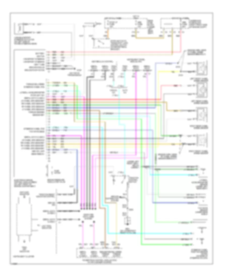
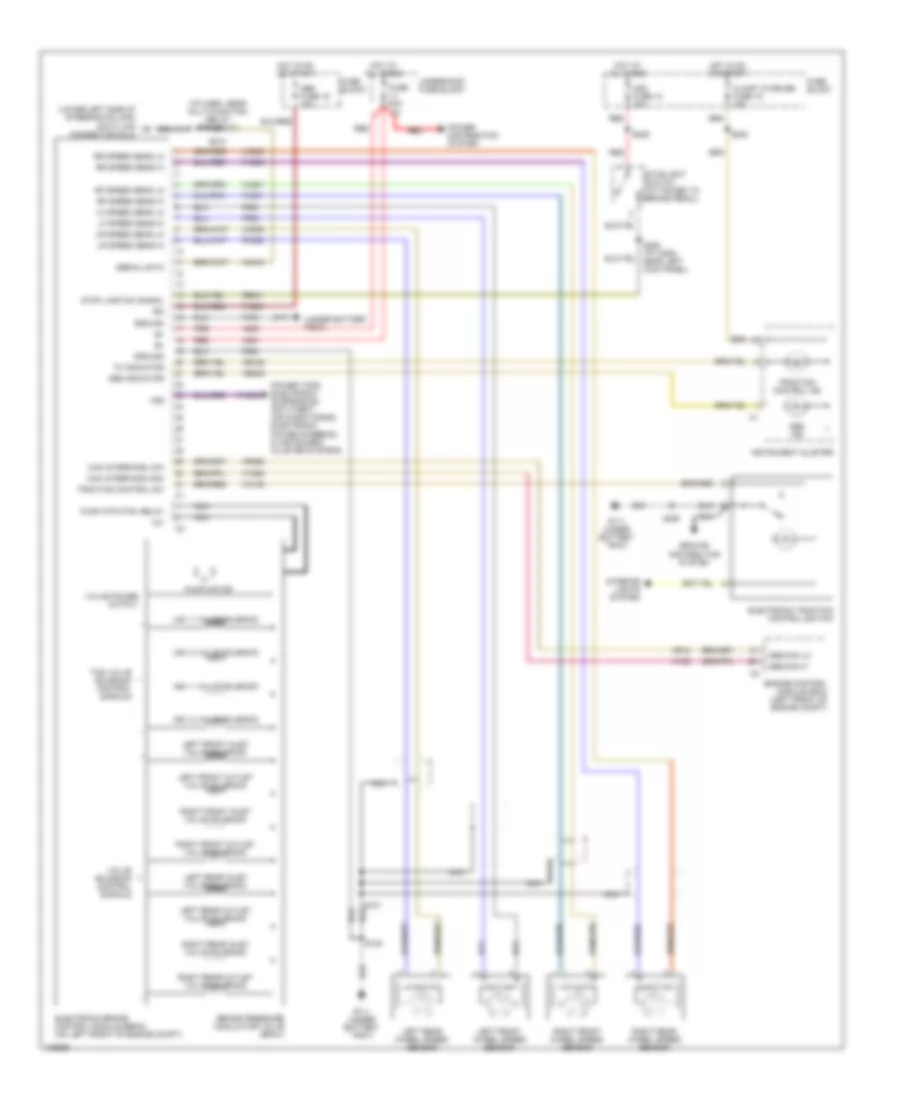
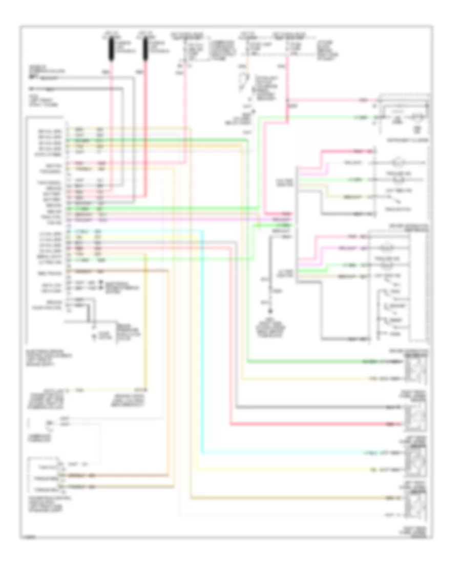
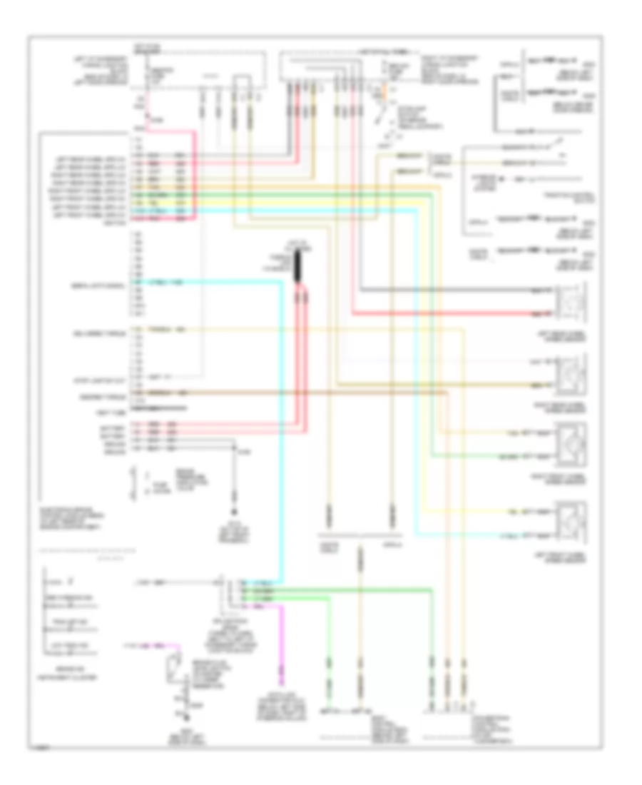
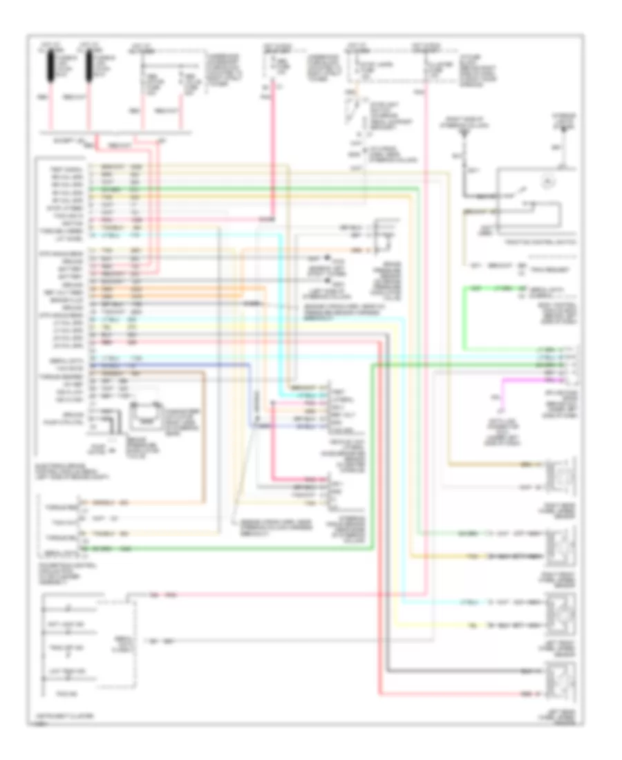
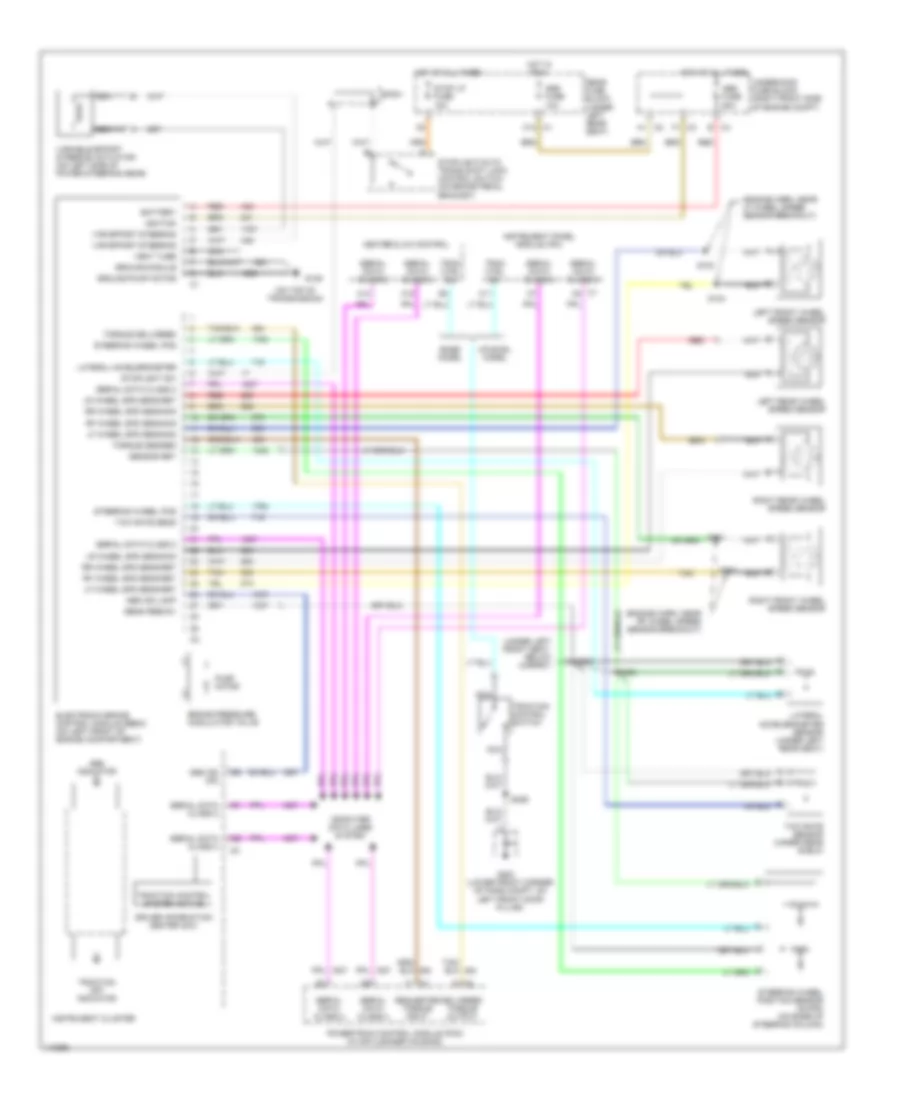
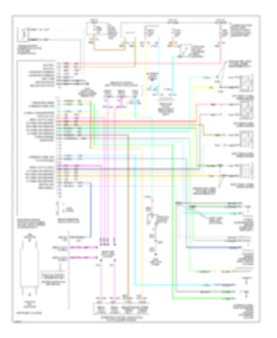
ALERO & GRAND AM
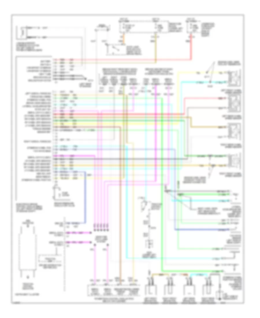
Anti-Lock Brakes Wiring Diagram (Alero & Grand Am) for Chevrolet RV Cutaway G2001 3500
 https://portal-diagnostov.com/license.html
Automotive Electricians Portal FZCO
Automotive Electricians Portal FZCO
https://portal-diagnostov.com/license.html
https://portal-diagnostov.com/license.html
Automotive Electricians Portal FZCO
Automotive Electricians Portal FZCO
List of elements for Anti-Lock Brakes Wiring Diagram (Alero & Grand Am) for Chevrolet RV Cutaway G2001 3500:
- (2.4l)
- (3.4l)
- (left side of dash)
- (left side of engine) g112
- (oldsmobile)
- (pontiac)
- (right rear of engine) g117
- (right side of dash)
- A10
- A11
- A12
- Abs fuse 50a
- Abs warning ind
- Abs/evo/ign fuse 15a
- B10
- B11
- Battery
- Body control module (bcm) (behind right side of dash)
- Brake fluid level switch (on master cylinder reservoir)
- Brake ind
- Brake pressure modulator valve
- Brk fluid lev sens sig
- C1 serial data
- C10
- C11
- Class 2 serial data
- Data link connector (dlc) (below dash, left of steering column)
- Electronic brake control module (ebcm) (inside left front fender)
- Electronic power steering system
- F12
- G201
- G202
- Ground
- Hot at all times
- Hot in run or start
- Ignition
- Instrument cluster
- Interior lights system
- Ipc/hvac batt fuse 10a
- Left front wheel speed sensor
- Left i/p fuse block (behind left side of dash)
- Left rear wheel speed sensor
- Lf whl spd sens low
- Lf whl spd sens sig
- Low ref
- Low trac ind
- Lr whl spd sens low
- Lr whl spd sens sig
- Nca
- Oldsmobile
- Pnk
- Pontiac
- Powertrain control module (pcm) (below left side of dash)
- Pump motor
- Red
- Rf whl spd sens low
- Rf whl spd sens sig
- Right front wheel speed sensor
- Right rear wheel speed sensor
- Rr whl spd sens low
- Rr whl spd sens sig
- Serial data
- Stop lamp supp
- Stop lps fuse 20a
- Stoplight switch (below left side of dash)
- Str whl pos sens (5v)
- Str whl pos sens sig
- Tan
- Trac cntl sw
- Trac off ind
- Traction control switch
- Underhood fuse block (in left side of engine compt, on strut tower)
- Var eff str act cntl
- Var eff str act supp
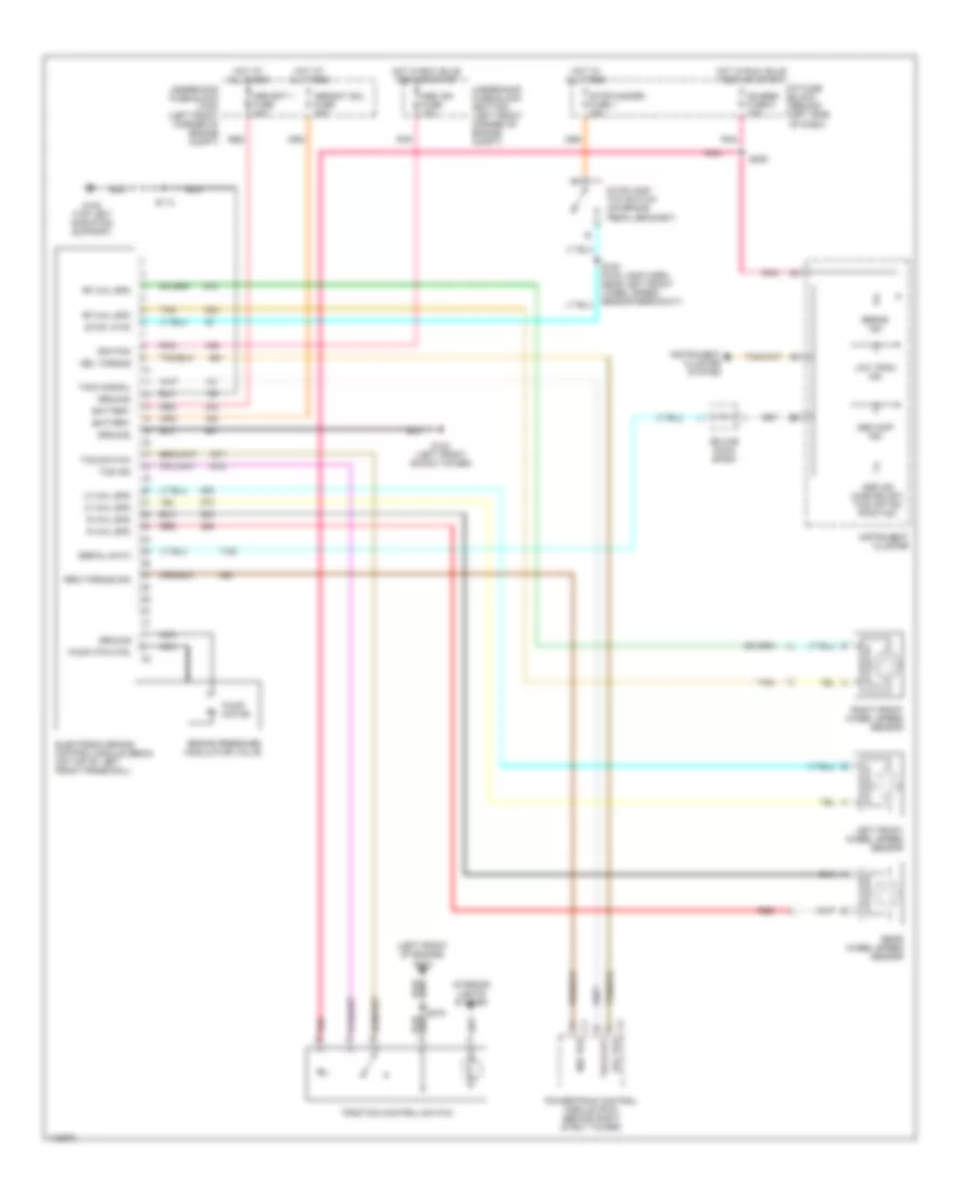
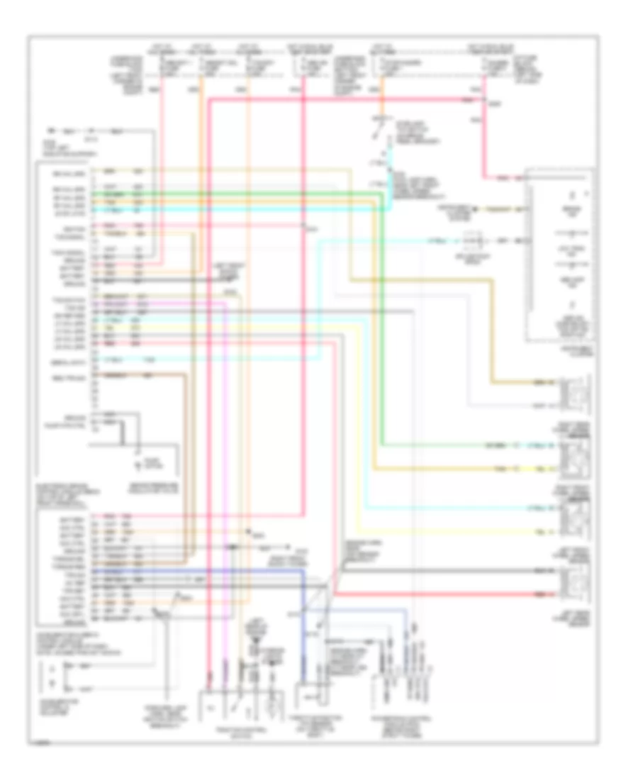
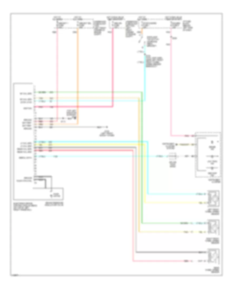
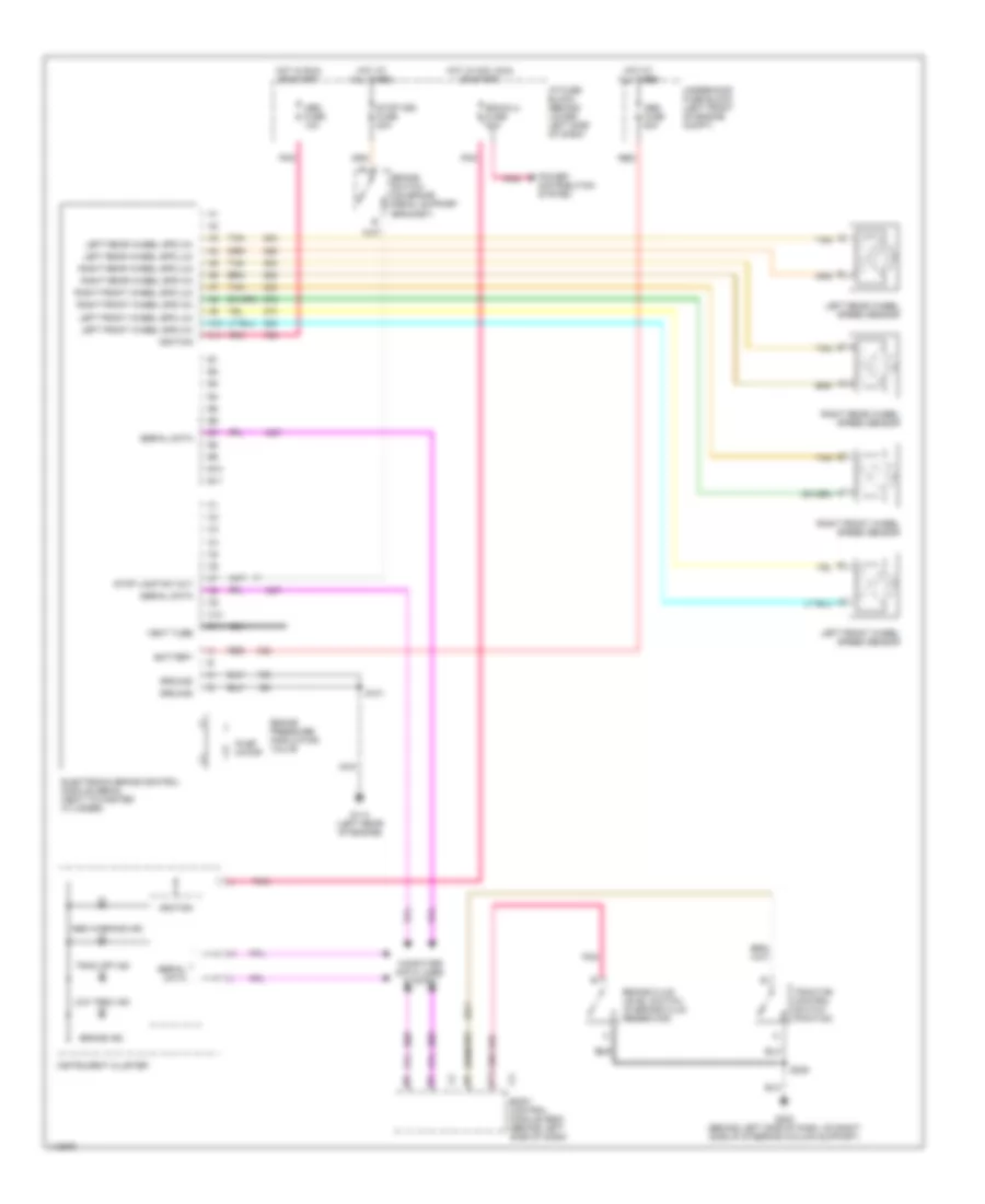
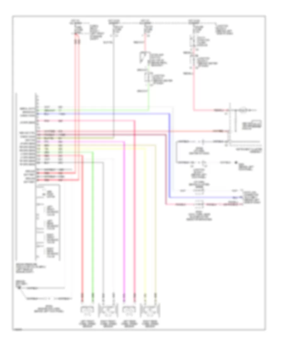
ASTRO & SAFARI
Anti-Lock Brakes Wiring Diagram (Astro & Safari) for Chevrolet RV Cutaway G2001 3500
List of elements for Anti-Lock Brakes Wiring Diagram (Astro & Safari) for Chevrolet RV Cutaway G2001 3500:
- (under left side of dash) data link connector (dlc)
- Abs fuse 60a
- Abs ind
- Brake fluid lvl sw
- Brake fuse 18 10a
- Brake pressure differential switch (on brake pressure modulator valve assembly)
- Brake sw output
- Breakout)
- Computer data lines system
- Cruise control system
- Electronic brake control module (ebcm) (on left front side of frame)
- Fuse output
- G108 (left front radiator support)
- G114 (left rear of engine)
- Ground
- Hot at all times
- Hot in run
- I/p fuse block (behind left side of dash)
- Instrument cluster
- Left front wheel speed sensor
- Lf whl spd sens ret
- Lf whl spd sens sig
- Nca
- Power distribution system
- Powertrain control module (pcm) (left side of engine compt)
- Radio batt fuse 19 10a
- Red
- Rf whl spd sens ret
- Rf whl spd sens sig
- Right front wheel speed sensor
- S110
- S127
- Serial data
- Splice pack sp261 (behind left side of dash)
- Stoplamp switch (above brake pedal)
- Tan
- Underhood fuse block (on left side of firewall)
- Vehicle speed out
- Vss
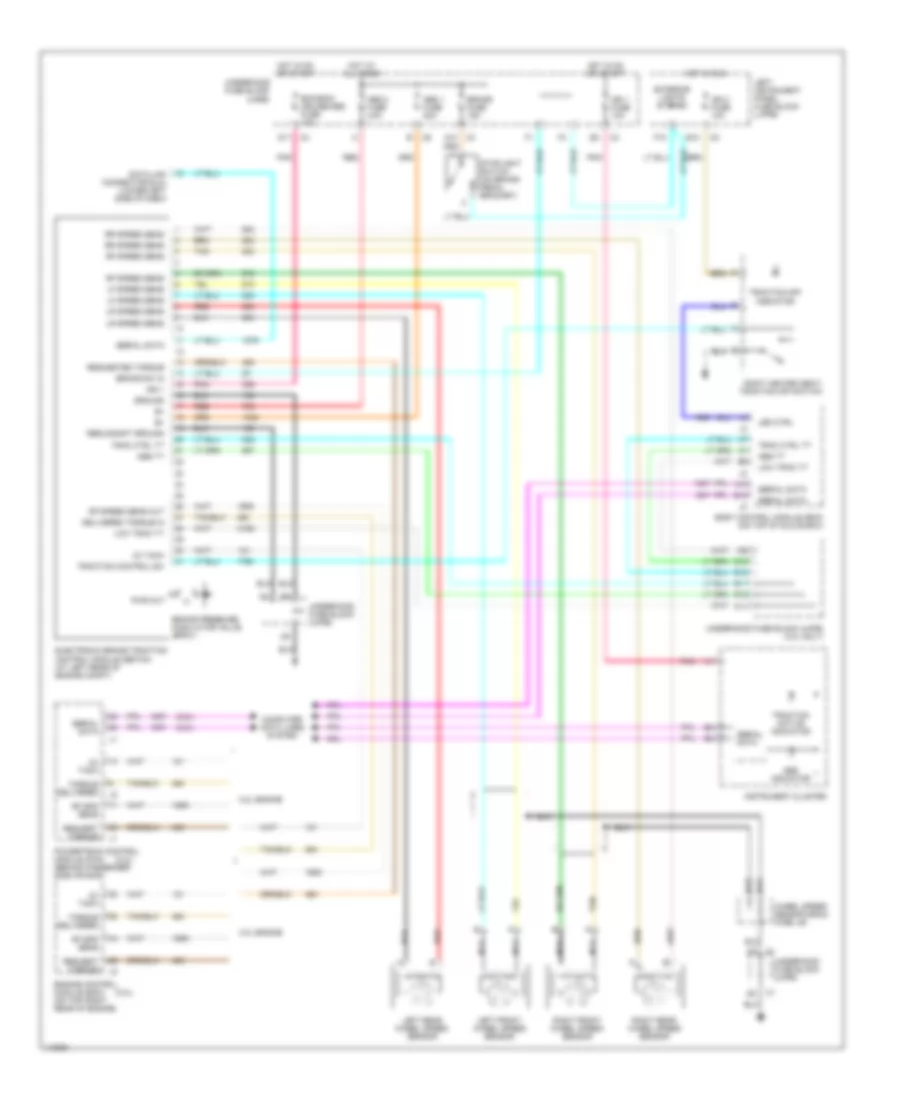
AURORA
Anti-Lock Brakes Wiring Diagram (Aurora) for Chevrolet RV Cutaway G2001 3500
List of elements for Anti-Lock Brakes Wiring Diagram (Aurora) for Chevrolet RV Cutaway G2001 3500:
- (behind right kick panel)
- (body harn, near forward crossmember under left front seat)
- (engine harn, near lf wheel speed sensor breakout)
- (engine harn, near rf wheel speed sensor breakout)
- (on brake pedal bracket) stoplight switch
- Abs fuse 10a
- Abs fuse 50a
- Abs ind
- Abs ind lamp
- Abs ind sig
- Battery
- Brake pressure modulator valve
- C1 (4.0l)
- C11
- C12
- C2 (3.5l)
- Computer data lines system
- Del torque
- Driver information center (dic)
- Electronic brake control module (ebcm) (under air cleaner housing)
- Flat wire
- G129 (on transmission) housing)
- G203
- Ground-module
- Ground-pump motor
- Hot at all times
- Hot in run
- Ignition 3
- Instrument cluster
- Instrument panel integration module (ipm) (at center of dash)
- Lateral accelerometer
- Lateral accelerometer sensor (under left rear seat)
- Left front wheel speed sensor
- Left rear wheel speed sensor
- Lf wheel spd sens-ret
- Lf wheel spd sens-sig
- Lr wheel spd sens-ret
- Lr wheel spd sens-sig
- Nca
- Powertrain control module (pcm) (under air cleaner)
- Pump motor
- Rear fuse block (under left rear seat)
- Red
- Req torque
- Rf wheel spd sens-ret
- Rf wheel spd sens-sig
- Right front wheel speed sensor
- Right rear wheel speed sensor
- Rr wheel spd sens-ret
- Rr wheel spd sens-sig
- S101
- S102
- S103
- S104
- S228
- S303
- S305
- Sens feed-5v
- Sensor ret
- Serial data
- Serial data class 2
- Serv stability sys
- Sp301 (near forward crossmember, under left front seat)
- Stability active
- Steering wheel pos
- Steering wheel position sensor (swps) (at base of steering column)
- Stop lp fuse 15a
- Stoplight sw
- Tan
- Torque delivered
- Torque desired
- Trac ctl sw
- Trac off ind
- Trac on ind
- Traction control switch
- Underhood fuse block (on right side of engine compt)
- Var effort steering
- Variable effort steering actuator (on top left end of steering gear)
- Vent tube
- Yaw rate sens
- Yaw rate sensor (under left rear seat, near battery)
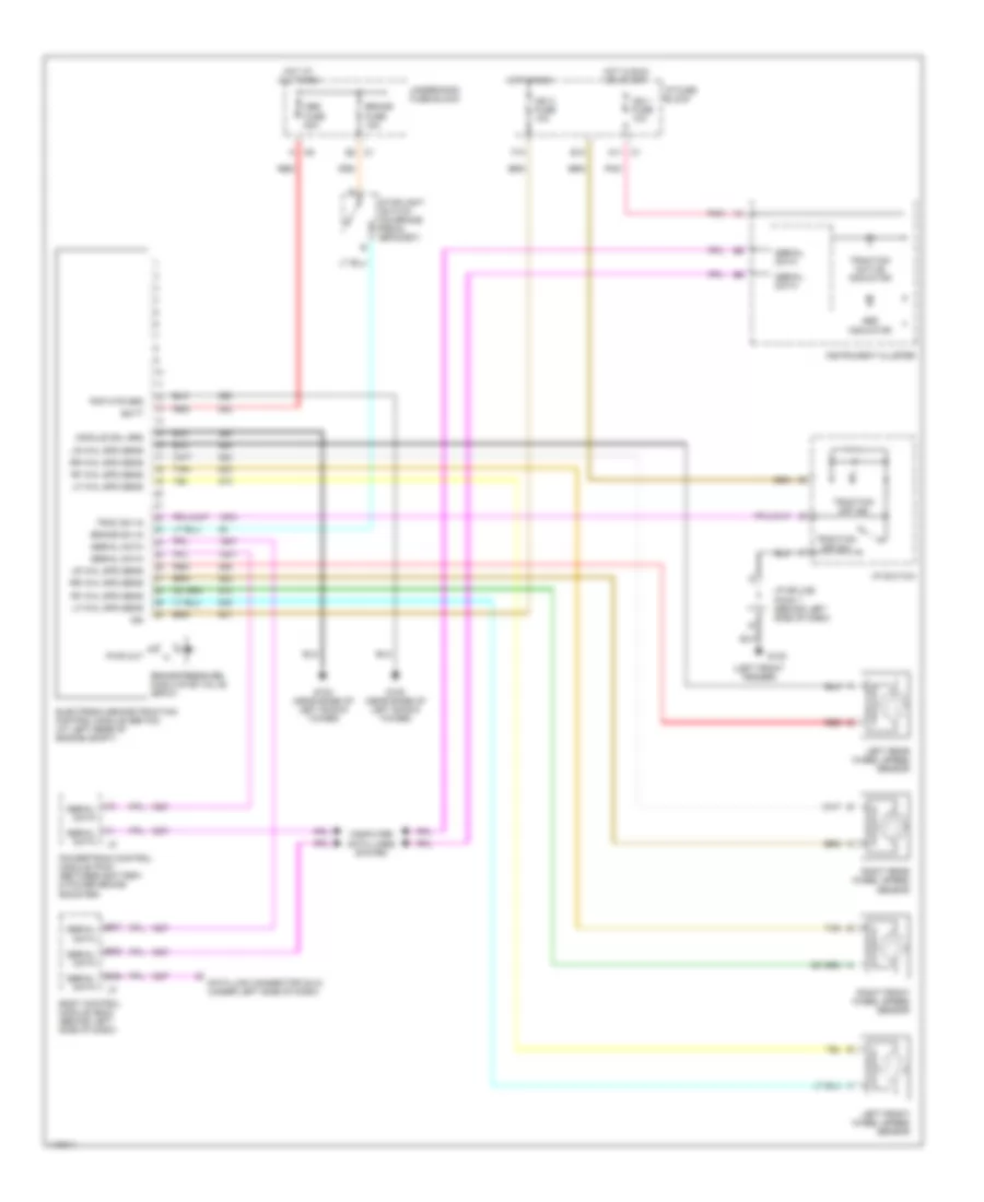
AZTEK
Anti-Lock Brakes Wiring Diagram (Aztek) for Chevrolet RV Cutaway G2001 3500
List of elements for Anti-Lock Brakes Wiring Diagram (Aztek) for Chevrolet RV Cutaway G2001 3500:
- A10
- A12
- Abs fuse 6 10a
- Abs ind
- Abs mtr fuse 36 40a
- Abs vlv fuse 9 25a
- Body control module (bcm)
- Brake ind
- Brake pressure modulator valve
- C10
- Center console fuse block
- Computer data lines system
- Del torque
- Del torque sig
- Electronic brake control module (ebcm)
- Eng spd sig
- Engine spd
- G130 (mounted on bellhousing, above starter)
- G201 (behind right side of dash)
- Gnd
- Hot at all times
- Hot in acc, run or start
- Hot in run or start
- Hzd fl fuse 15a
- Ign 0
- Ign 0 fuse 2a
- Ignition
- Instrument cluster
- Left front wheel speed sensor
- Left rear wheel speed sensor
- Lf whl spd
- Lr whl spd
- Nca
- Pnk
- Powertrain control module (pcm)
- Pump gnd
- Pump motor
- Red
- Req torque
- Req torque sig
- Rf whl spd
- Right front wheel speed sensor
- Right rear wheel speed sensor
- Rr whl spd
- S213
- Serial data
- Service traction system ind
- Stop lp sw
- Stoplamp switch
- Tan
- Trac off ind
- Trac sw
- Traction active ind
- Traction control switch
- Underhood fuse block
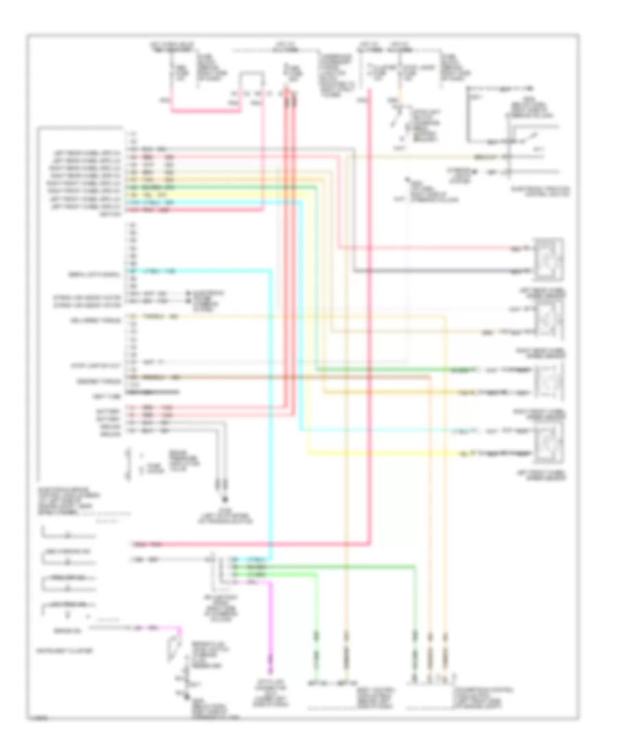
BLAZER, BRAVADA, JIMMY, SONOMA & S10 PICKUP
Anti-Lock Brakes Wiring Diagram (Blazer, Bravada, Jimmy, Sonoma & S10 Pickup) for Chevrolet RV Cutaway G2001 3500
List of elements for Anti-Lock Brakes Wiring Diagram (Blazer, Bravada, Jimmy, Sonoma & S10 Pickup) for Chevrolet RV Cutaway G2001 3500:
- (under left side of dash) data link connector (dlc)
- 2.2l
- 4.3l
- A10
- A12
- Abs fuse 22 10a
- Abs fuse 60a
- Anti-lock indicator
- Axle switch sig
- Axle switch signal
- Battery
- Body control module (bcm) (under dash, on heater case)
- Brake fluid level switch (on master cylinder)
- Brake fluid lvl sig
- Brake warning indicator
- Class 2
- Computer data lines system
- Electronic brake control module (ebcm) (on left front inner fender)
- Engine controls system
- Except bravada & 2.2l w/o cruise
- Front axle indicator switch (on front axle, right of differential)
- G106 (behind left headlamp)
- G117 (4.3l) (right rear of engine)
- G119 (2.2l) (right front of engine) block)
- Ground
- Hot at all times
- Hot in run
- I/p fuse block (on left end of dash)
- Ignition 3
- Instrument cluster
- Left front wheel speed sensor
- Lf whl spd sens ref
- Lf whl spd sens sig
- Nca
- Powertrain control module (pcm) (on right front of engine compt)
- Pump motor
- Rdo batt fuse 19 15a
- Red
- Rf whl spd sens ref
- Rf whl spd sens sig
- Right front wheel speed sensor
- S121 (body harn, near ebcm)
- S203
- S240
- Serial data
- Splice pack sp201 (on body harn, behind left side of dash)
- Stoplight switch (on brake pedal support bracket)
- Tan
- Tcc brake switch sig
- Underhood fuse block
- Underhood fuse block (on top of left front fender)
- Vehicle speed signal
- Vss
BONNEVILLE
Anti-Lock Brakes Wiring Diagram (Bonneville) for Chevrolet RV Cutaway G2001 3500
List of elements for Anti-Lock Brakes Wiring Diagram (Bonneville) for Chevrolet RV Cutaway G2001 3500:
- (engine harn, near lf wheel speed sensor breakout)
- (engine harn, near rf wheel speed sensor breakout)
- (on top of transmission)
- (under left front seat, below carpet)
- A1 c2
- Abs fuse 10a
- Abs fuse 50a
- Abs ind lamp
- Abs ind sig
- Antilock indicator
- Auto a/c
- B c4
- Battery
- Brake pressure modulator valve
- C1 c8
- C11
- C12 c1
- C3 f1
- Computer data lines system
- Delivered torque output
- Electronic brake control module (ebcm) (on left front of engine compartment)
- G129
- G901 (on lower right front "a" pillar)
- Ground distribution system
- Ground-module
- Ground-pump motor
- Heater & a/c control
- Hot at all times
- Hot in run
- Ignition
- Instrument cluster
- Instrument panel module (ipm)
- Lateral accelerometer
- Lateral accelerometer sensor (under left rear seat)
- Left front wheel speed sensor
- Left rear wheel speed sensor
- Lf wheel spd sens-ret
- Lf wheel spd sens-sig
- Low trac indicator
- Lr wheel spd sens-ret
- Lr wheel spd sens-sig
- Manual a/c
- Nca
- Powertrain control module (pcm) (in air cleaner housing)
- Pump motor
- Rear fuse block (under left rear seat)
- Red
- Requested torque input
- Rf wheel spd sens-ret
- Rf wheel spd sens-sig
- Right front wheel speed sensor
- Right rear wheel speed sensor
- Rr wheel spd sens-ret
- Rr wheel spd sens-sig
- S101
- S102
- S103
- S104
- S205
- S303
- S305
- Sens feed-5v
- Sensor ret
- Serial data class 2
- Sp301
- Steering wheel pos
- Steering wheel position sensor (swps) (on base of steering column)
- Stop lp fuse 15a
- Stoplight sw
- Stoplight/auto trans shift lock control switch (on brake pedal bracket)
- Tan
- Torque delivered
- Torque desired
- Trac ctrl sw
- Trac off indicator
- Traction control switch
- Traction ready indicator control
- Underhood fuse block (right front side of engine compt)
- Var effort steering
- Variable effort steering actuator (on left side of power steering gear)
- Vent tube
- Yaw rate sens
- Yaw rate sensor (under rear shelf)
CAMARO & FIREBIRD
Anti-Lock Brakes Wiring Diagram (Camaro & Firebird - 3.8L - With Traction Control) for Chevrolet RV Cutaway G2001 3500
List of elements for Anti-Lock Brakes Wiring Diagram (Camaro & Firebird - 3.8L - With Traction Control) for Chevrolet RV Cutaway G2001 3500:
- (left front of engine) g110
- Abs bat 1 fuse 40a
- Abs bat sol fuse 25a
- Abs ign fuse 10a
- Abs inop ind
- Asr ind (chevrolet) tcs off ind (pontiac)
- Battery
- Brake ind
- Brake pressure modulator valve
- C1 req tor
- C2 del tor
- Del torque
- Electronic brake control module (ebcm) (on top of left front frame rail)
- G102 (left front shock tower)
- G108 (top left radiator support)
- Gauges fuse 9 10a
- Ground
- Hot at all times
- Hot in run, bulb test or start
- I/p fuse block (behind left side of dash)
- Ignition
- Instrument cluster
- Instrument cluster system
- Interior lights system
- Left front wheel speed sensor
- Lf whl spd
- Low trac ind
- Nca
- Pnk
- Pnk b
- Powertrain control module (pcm) (behind right strut tower)
- Pump motor
- Pump mtr ctrl
- R whl spd
- Rear wheel speed sensor
- Red
- Req torque sig
- Rf whl spd
- Right front wheel speed sensor
- S113
- S206
- S215
- Serial data
- Splice pack sp200
- Stop lp fd
- Stop/hazard fuse 1 20a
- Stoplamp/ tcc switch (on brake pedal bracket)
- Tach out
- Tach signal
- Tan
- Tcs ind
- Tcs switch
- Traction control switch
- Underhood fuse block (bottom) (left front corner of engine compt)
- Underhood fuse block (top) (left front corner of engine compt)
Anti-Lock Brakes Wiring Diagram (Camaro & Firebird - 5.7L - With Traction Control) for Chevrolet RV Cutaway G2001 3500
List of elements for Anti-Lock Brakes Wiring Diagram (Camaro & Firebird - 5.7L - With Traction Control) for Chevrolet RV Cutaway G2001 3500:
- (engine harn, a/t-near a/t breakout, m/t-near vss breakout)
- (engine harn, near map sensor breakout)
- (forward lamp harn, near ignition switch breakout)
- (left front shock tower)
- (left rear of engine) g114
- (right front shock tower)
- +5v
- +5v ref
- Abs bat 1 fuse 40a
- Abs bat sol fuse 25a
- Abs ign fuse 10a
- Abs inop ind
- Acc crtl
- Acc ctrl
- Accelerator & servo control module (under left side of dash)
- Accelerator control & adjuster
- Asr ind (chevrolet) tcs off ind (pontiac)
- Battery
- Brake ind
- Brake pressure modulator valve
- Electronic brake control module (ebcm) (on top of left front frame rail)
- G102
- G103
- G108 (top left radiator support)
- Gauges fuse 9 10a
- Ground
- Hot at all times
- Hot in run, bulb test or start
- I/p fuse block (behind left side of dash)
- Ign retard
- Ignition
- Instrument cluster
- Instrument cluster system
- Interior lights system
- Left front wheel speed sensor
- Left rear wheel speed sensor
- Lf whl spd
- Low trac ind
- Lr whl spd
- Nca
- Note: unused pins not shown
- Pnk
- Pnk b
- Powertrain control module (pcm) (behind right strut tower)
- Pump motor
- Pump mtr ctrl
- Red
- Req tps sig
- Rf whl spd
- Right front wheel speed sensor
- Right rear wheel speed sensor
- Rr whl spd
- S113
- S116
- S118
- S119
- S154 (fwd lamp harn, near left front wheel speed sensor breakout)
- S181
- S203
- S204
- S205
- S206
- S209
- S215
- Sens gnd
- Serial data
- Spk rtd
- Splice pack sp200
- Stop lp fd
- Stop/hazard fuse 1 20a
- Stoplamp/ tcc switch (on brake pedal bracket)
- Tach out
- Tach signal
- Tan
- Tcs bat fuse 20a
- Tcs ind
- Tcs signal
- Tcs switch
- Throttle position (tp) sensor (on throttle body)
- Torque del
- Torque req
- Tp sens
- Tps ret
- Tps sig
- Traction control switch
- Underhood fuse block (bottom) (left front corner of engine compt)
- Underhood fuse block (top) (left front corner of engine compt)
Anti-Lock Brakes Wiring Diagram (Camaro & Firebird - 3.8L & 5.7L - Without Traction Control) for Chevrolet RV Cutaway G2001 3500
List of elements for Anti-Lock Brakes Wiring Diagram (Camaro & Firebird - 3.8L & 5.7L - Without Traction Control) for Chevrolet RV Cutaway G2001 3500:
- (top left radiator support) g108
- Abs bat 1 fuse 40a
- Abs bat sol fuse 25a
- Abs ign fuse 10a
- Abs inop ind
- Battery
- Brake ind
- Brake pressure modulator valve
- Electronic brake control module (ebcm) (on top of left front frame rail)
- G102 (left front shock tower)
- Gauges fuse 9 10a
- Ground
- Hot at all times
- Hot in run, bulb test or start
- I/p fuse block (behind left side of dash)
- Ignition
- Instrument cluster
- Instrument cluster system
- Left front wheel speed sensor
- Lf whl spd
- Low trac ind
- Nca
- Pnk
- Pump motor
- Pump mtr ctrl
- Rear wheel speed sensor
- Rear whl spd
- Red
- Rf whl spd
- Right front wheel speed sensor
- S113
- S154 (fwd lamp harn, near left front front wheel speed sensor breakout)
- S206
- Serial data
- Splice pack sp200
- Stop lp fd
- Stop/hazard fuse 1 20a
- Stoplamp/ tcc switch (on brake pedal bracket)
- Tan
- Underhood fuse block (bottom) (left front corner of engine compt)
- Underhood fuse block (top) (left front corner of engine compt)
CATERA
Anti-Lock Brakes Wiring Diagram (Catera) for Chevrolet RV Cutaway G2001 3500
List of elements for Anti-Lock Brakes Wiring Diagram (Catera) for Chevrolet RV Cutaway G2001 3500:
- (i/p harn, near multi-function relay breakout)
- (lower left side of steering column) data link connector (dlc)
- (under battery tray)
- 12v
- A290
- A291
- Abs can hi
- Abs can lo
- Abs fuse 19 10a
- Abs ind
- Abs indicator
- Asv 1 valve solenoid
- Asv 2 valve solenoid
- Brake pressure modulator valve (bpmv)
- Can interface high
- Can interface low
- Clamp 15 cruise fuse 15 15a
- Electronic brake control module (ebcm) (on left front of engine compt)
- Electronic traction control switch
- Engine control module (ecm) (left front of engine compt)
- F350
- F372
- F390
- Fa202
- Fb301
- Fuse block
- Fuse v1 80a
- G111
- G111 (under battery tray)
- Ground
- Ground distribution system
- Hot at all times
- Hot in on or start
- Hzd fuse 12 20a
- Ign
- Instrument cluster
- Interior lights system
- Left front inlet valve solenoid
- Left front outlet valve solenoid
- Left front wheel speed sensor
- Left rear inlet valve solenoid
- Left rear outlet valve solenoid
- Left rear wheel speed sensor
- Lf speed sens hi
- Lf speed sens lo
- Lr speed sens hi
- Lr speed sens lo
- Nca
- P350
- Pa253
- Pa900
- Pm253
- Power distribution system
- Power tops, electronic suspension, anti-theft, air conditioning, electronic power steering, & instrument cluster systems
- Pu251
- Pump motor
- Pump mtr ctrl relay
- Red
- Rf speed sens hi
- Rf speed sens lo
- Right front inlet valve solenoid
- Right front outlet valve solenoid
- Right front wheel speed sensor
- Right rear inlet valve solenoid
- Right rear outlet valve solenoid
- Right rear wheel speed sensor
- Rr speed sens hi
- Rr speed sens lo
- S105
- S107
- S200
- S206 (i/p harn, near left kick panel)
- S210
- S229
- S250
- Serial data
- Stop lamp sw signal
- Stoplight switch (attached to brake pedal)
- Tc indicator
- Tcs valve solenoid control signals
- Traction control ind
- Traction control sw
- Underhood fuse block
- Usv 1 valve solenoid
- Usv 2 valve solenoid
- Valve power output
- Valve solenoid control signals
- Vss
- Xa105
- Xa253
- Xb105
- Xb305
- Xm218
- Xm253
- Xr12
- Xr888
- Xu251
- Xy29
- Xy888
CAVALIER & SUNFIRE
Anti-Lock Brakes Wiring Diagram (Cavalier & Sunfire) for Chevrolet RV Cutaway G2001 3500
List of elements for Anti-Lock Brakes Wiring Diagram (Cavalier & Sunfire) for Chevrolet RV Cutaway G2001 3500:
- A10
- A11
- Abs fuse 10a
- Abs fuse 50a
- Abs warning ind
- B10
- B11
- Battery
- Bcm/clu fuse 10a
- Body control module (bcm) (behind left side of dash)
- Brake fluid level switch (in brake fluid reservoir)
- Brake ind
- Brake pressure modulator valve
- Brake switch (on brake pedal support bracket)
- C10
- C11
- Computer data lines system
- Electronic brake control module (ebcm) (next to master cylinder)
- G114 (left rear of engine)
- G202 (behind left side of dash, on right side of steering column support)
- Ground
- Hot at all times
- Hot in acc, run, or start
- Hot in run or start
- I/p fuse block (behind lower left side of dash)
- Ignition
- Instrument cluster
- Left front wheel spd (hi)
- Left front wheel spd (lo)
- Left front wheel speed sensor
- Left rear wheel spd (hi)
- Left rear wheel spd (lo)
- Left rear wheel speed sensor
- Low trac ind
- Nca
- Pnk
- Power distribution system
- Pump motor
- Red
- Right front wheel spd (hi)
- Right front wheel spd (lo)
- Right front wheel speed sensor
- Right rear wheel spd (hi)
- Right rear wheel spd (lo)
- Right rear wheel speed sensor
- S101
- S205
- Serial data
- Stop hzd fuse 20a
- Stop lamp sw out
- Tan
- Trac off ind
- Traction control switch (pontiac)
- Underhood fuse block (left front of engine compt)
- Vent tube
CENTURY & REGAL
Anti-Lock Brakes Wiring Diagram (Century & Regal) for Chevrolet RV Cutaway G2001 3500
List of elements for Anti-Lock Brakes Wiring Diagram (Century & Regal) for Chevrolet RV Cutaway G2001 3500:
- A10
- A11
- Abs fuse 10a
- Abs fuse 60a
- Abs warning ind
- B10
- B11
- B12
- Battery
- Body control module (bcm) (behind left side of dash)
- Brake fluid level switch (in brake fluid reservoir)
- Brake ind
- Brake pressure modulator valve
- C10
- C11
- Cluster fuse 10a
- Data link connector (dlc) (under left side of dash)
- Delivered torque
- Desired torque
- Electronic brake control module (ebcm) (at left side of engine compt, near strut tower)
- Electronic power steering system
- Electronic traction control switch
- Fuse block (behind right side of dash)
- G129 (left of starter, on transaxle stud)
- G205 (below dash, right side of steering column)
- Ground
- Hot at all times
- Hot in run, bulb test or start
- Ignition
- Instrument cluster
- Interior lights system
- Left front wheel spd (hi)
- Left front wheel spd (lo)
- Left front wheel speed sensor
- Left rear wheel spd (hi)
- Left rear wheel spd (lo)
- Left rear wheel speed sensor
- Low trac ind
- Nca
- Pnk
- Powertrain control module (pcm) (left front side of engine compt)
- Pump motor
- Red
- Right front wheel spd (hi)
- Right front wheel spd (lo)
- Right front wheel speed sensor
- Right rear wheel spd (hi)
- Right rear wheel spd (lo)
- Right rear wheel speed sensor
- S205 (i/p harn, right side of steering column)
- S211
- Serial data signal
- Splice pack sp205 (right side of steering column)
- Stop lamp sw out
- Stop lamps fuse 15a
- Stoplight switch (on brake pedal support bracket)
- Strng var assist motor
- Tan
- Trac off ind
- Underhood accessory wiring junction block (mounted to right strut tower)
- Vent tube
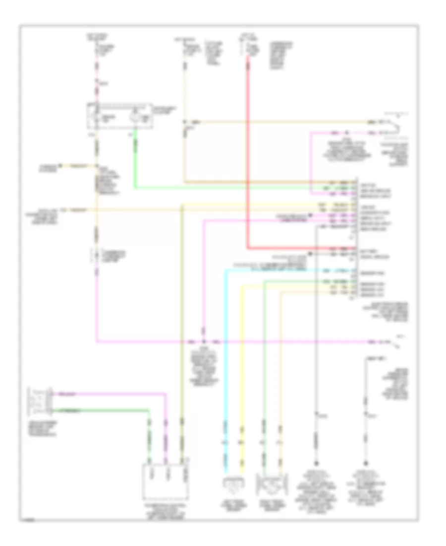
CHEVY EXPRESS & SAVANA
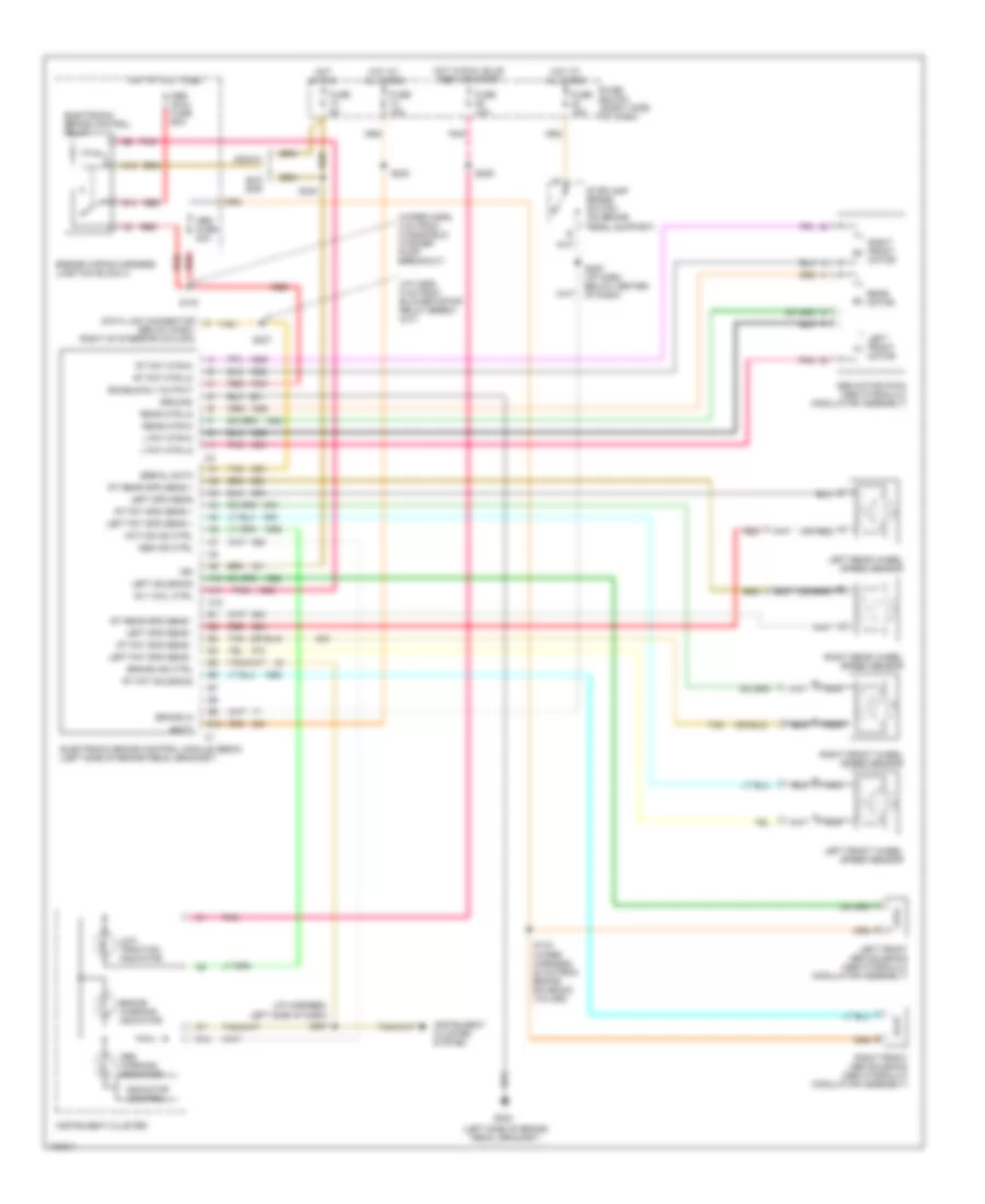
Anti-Lock Brakes Wiring Diagram (Chevy Express & Savana - Except 6.5L) for Chevrolet RV Cutaway G2001 3500
List of elements for Anti-Lock Brakes Wiring Diagram (Chevy Express & Savana - Except 6.5L) for Chevrolet RV Cutaway G2001 3500:
- (4.3l,5.0l,5.7l) g125 (8.1l) g114 (4.3l,5.0l,5.7l: at generator bracket) (8.1l: rear of left cyl head)
- A13
- Abs fuse 60a
- Abs ind
- Abs ind ground
- B17
- Battery
- Brake fuse 18 10a
- Brake ind
- Brake ind input
- Brake pressure differential switch (on left frame rail, near center of vehicle)
- Brake sw input
- Computer data lines system
- Data link connector (dlc) (under left side of dash)
- Diagnostic sig
- Ebcm ground
- Electronic brake control module (ebcm) (on left frame rail, near center of vehicle)
- G100 (4.3l) g125 (5.0l,5.7l) g114 (8.1l) (4.3l: left side of engine compt, near fender well) (5.ol,5.7l: front of engine, near thermo- stat housing) (8.1l: rear of left cyl head)
- G125 (4.3l) g117 (5.0l,5.7l) g114 (8.1l) (4.3l: at generator bracket) (5.ol,5.7l: rear of right cyl head) (8.1l: rear of left cyl head)
- Gauges fuse 4 10a
- Hot at all times
- Hot in run
- Hot in run or start
- I/p fuse block (on left lower kick panel)
- Ignition
- Instrument cluster
- Left front wheel speed sensor
- Pnk
- Powertrain control module (pcm) (in engine compt, on left inner fender)
- Red
- Right front wheel speed sensor
- S101
- S102
- S154 (engine harn, 97 cm from underhood fuse/relay center, toward a/c compressor clutch breakout)
- S156 (4.3l,5.0l,5.7l: engine harn, near fuel inj breakout) (8.1l: engine harn, near vehicle speed sensor breakout)
- S216
- S235 (i/p harn, near park brake warning switch breakout)
- Sensor high
- Sensor low
- Serial data
- Signal ground
- Tan
- Tcc/stoplamp switch (behind dash, on brake pedal support)
- Underhood fuse/relay center
- Underhood fuse/relay center (on left side of engine compt)
- Vehicle speed sensor (vss) (on side of transmission)
- Vss (+)
- Vss (-)
- Vss sig
- Warning systems
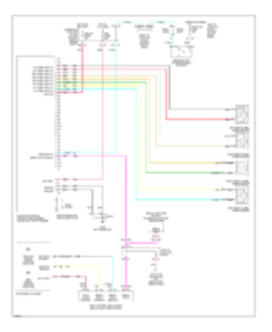
Anti-Lock Brakes Wiring Diagram (Chevy Express & Savana - 6.5L) for Chevrolet RV Cutaway G2001 3500
List of elements for Anti-Lock Brakes Wiring Diagram (Chevy Express & Savana - 6.5L) for Chevrolet RV Cutaway G2001 3500:
- A13
- Abs fuse 60a
- Abs ind
- Abs ind ground
- B17
- Battery
- Brake fuse 18 10a
- Brake ind
- Brake ind input
- Brake pressure differential switch (on left frame rail, near center of vehicle)
- Brake sw input
- Computer data lines system
- Data link connector (dlc) (under left side of dash)
- Diagnostic sig
- Ebcm ground
- Electronic brake control module (ebcm) (on left frame rail, near center of vehicle)
- G110 (left front of engine, at a/c compressor)
- G125 (at generator bracket)
- G125 (front of engine, near thermostat housing)
- Gauges fuse 4 10a
- Hot at all times
- Hot in run
- Hot in run or start
- I/p fuse block (on left lower kick panel)
- Ignition
- Instrument cluster
- Left front wheel speed sensor
- Pnk
- Red
- Right front wheel speed sensor
- S101
- S102
- S111 (engine harn, near a/c compressor clutch breakout)
- S156 (engine harn, near brake pressure differential switch breakout)
- S210
- S216
- S235 (i/p harn, near park brake warning switch breakout)
- Sensor high
- Sensor low
- Serial data
- Signal ground
- Tan
- Tcc/stoplamp switch (behind dash, on brake pedal support)
- Underhood fuse/relay center
- Underhood fuse/relay center (on left side of engine compt)
- Vehicle speed sensor (vss) (on side of transmission)
- Vehicle speed sensor (vss) buffer (below dash, near steering column)
- Vss (+)
- Vss (-)
- Vss sig
- Warning systems
CORVETTE
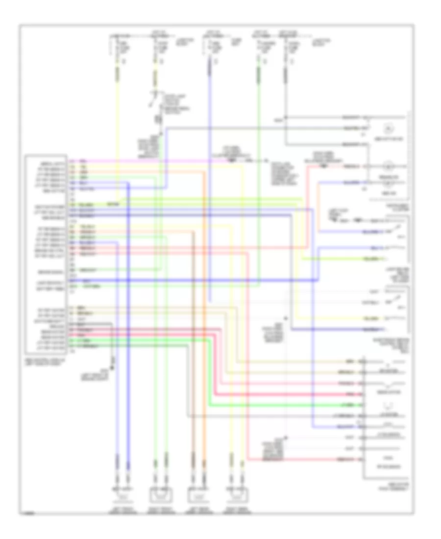
Anti-Lock Brakes Wiring Diagram (Corvette) for Chevrolet RV Cutaway G2001 3500
List of elements for Anti-Lock Brakes Wiring Diagram (Corvette) for Chevrolet RV Cutaway G2001 3500:
- (forward lamp harn, near ebcm connector breakout)
- (i/p harn, near yaw rate sensor)
- (on left frame rail) g113
- (under battery tray) g111
- A11
- A13
- Abs fuse 52 40a
- Abs ind
- Abstrns fuse 5 10a
- Battery
- Body control module (bcm) (in right footwell)
- Brake fluid pressure sensor (near master cylinder)
- Brake press sens sig
- Brake pressure modulator valve
- C2 c7
- Class 2 serial data
- Computer data lines system
- D15
- Del torque
- Del torque sig
- Electronic brake control module (ebcm) (at left front side of engine compt)
- Electronic suspension control (esc) module (in rear compt, inside rear tub)
- G200
- Ground
- Hot at all times
- Hot in run
- Hot in run or start
- I/p fuse block (in right front footwell)
- Ignition 1
- Ignition 3
- Instrument cluster
- Ipc fuse 19 10a
- Lateral accel in
- Lateral accelerometer sensor (under right seat)
- Left front wheel speed sensor
- Left rear wheel speed sensor
- Lf whl spd sens low
- Lf whl spd sens sig
- Low ref
- Lr whl spd sens low
- Lr whl spd sens sig
- Nca
- Pnk
- Powertrain control module (pcm) (on right side of engine compt)
- Pump motor
- Red
- Req torque
- Request torque sig
- Rf whl spd sens low
- Rf whl spd sens sig
- Right front wheel speed sensor
- Right rear wheel speed sensor
- Rr whl spd sens low
- Rr whl spd sens sig
- S106
- S108
- S308
- S310
- Serial data
- Sp201 (left kick panel)
- Steering wheel position sensor (swps) (at base of steering column)
- Stoplamp sw
- Stoplight switch (on top of brake pedal support)
- Stp haz fuse 8 20a
- Str pos sens sig
- Str whl pos sens 5v ref
- Str whl pos sig a
- Str whl pos sig b
- Tan
- Trac sw
- Traction ind
- Traction/ suspension control switch
- Underhood fuse block (on right rear of engine compt)
- Var eff str act hi
- Var eff str act low
- Variable effort steering actuator (on left side of steering rack assembly)
- Yaw rate sens sig
- Yaw rate sensor (under hvac control head)
DEVILLE
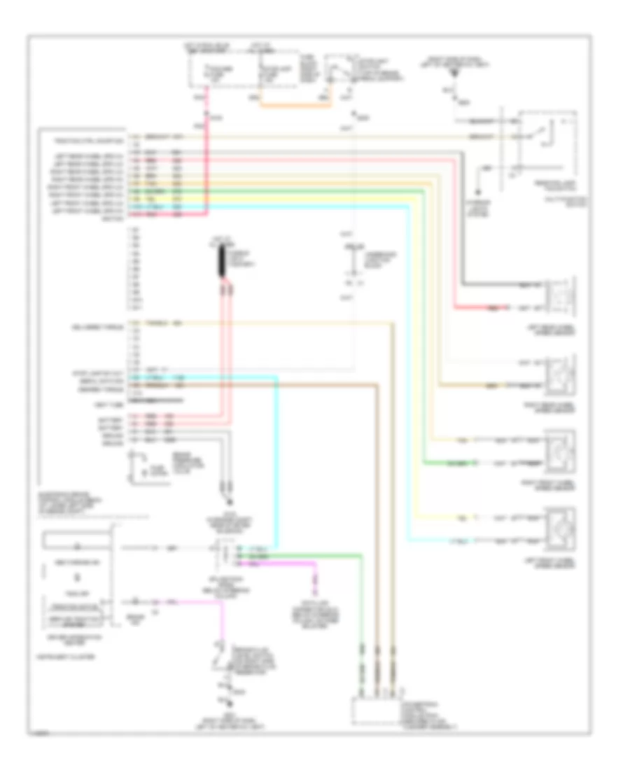
Anti-Lock Brakes Wiring Diagram (DeVille) for Chevrolet RV Cutaway G2001 3500
List of elements for Anti-Lock Brakes Wiring Diagram (DeVille) for Chevrolet RV Cutaway G2001 3500:
- (above radio) instrument panel integration module (ipm)
- (behind right rear seat back) electronic suspension control module
- (body harness, 66 cm from bulk- head connector near park brake pedal)
- (body harness, near base of left strut tower)
- (engine harn, near camshaft position sensor connector)
- (engine harn, near master cylinder)
- (on left side of radiator support)
- A (or c)
- Abs fuse 10a
- Abs fuse 50a
- Abs ind lamp
- Abs ind sig
- Abs indicator
- B c4
- B10
- Battery
- Brake pressure modulator valve
- C1 b11
- C1 c12
- C2 a11
- C5 c1
- Computer data lines system
- Delivered torque output
- Driver information center (dic)
- Electronic brake control module (ebcm) (under air cleaner housing)
- G108
- G316 (under right front door sill trim plate)
- Ground-module
- Ground-pump motor
- Hot at all times
- Hot in run
- Ignition pos voltage
- Instrument cluster
- Lateral accelerometer
- Lateral accelerometer sensor (under left rear seat)
- Left force d15
- Left front wheel speed sensor
- Left normal force sig
- Left rear wheel speed sensor
- Lf wheel spd sens-ret
- Lf wheel spd sens-sig
- Lr wheel spd sens-ret
- Lr wheel spd sens-sig
- Nca
- Powertrain control module (pcm) (inside air cleaner)
- Pump motor
- Rear fuse block (under left rear seat)
- Red
- Requested torque input
- Rf wheel spd sens-ret
- Rf wheel spd sens-sig
- Right force c7
- Right force d14
- Right front wheel speed sensor
- Right normal force sig
- Right rear wheel speed sensor
- Rr wheel spd sens-ret
- Rr wheel spd sens-sig
- S101
- S102
- S103
- S104
- S211
- S212
- Sens feed-5v
- Sensor ret
- Serial data class 2
- Serial data d4
- Sp302 (in body harn, near cross car channel)
- Steering wheel pos
- Steering wheel position
- Steering wheel position sensor (swps) (on base of steering column)
- Stop lp fuse 15a
- Stoplight sw
- Stoplight/auto- matic transmission shift interlock control switch (near top of brake pedal)
- Tan
- Torque delivered
- Torque desired
- Trac ctrl sw
- Traction control switch
- Traction off
- Traction off indicator
- Underhood fuse block (at right side of engine compt)
- Var effort steering
- Variable effort steering actuator (on left side of power steering gear)
- Vent tube
- Yaw rate sens
- Yaw rate sensor (under left side of rear shelf)
ELDORADO
Anti-Lock Brakes Wiring Diagram (Eldorado) for Chevrolet RV Cutaway G2001 3500
List of elements for Anti-Lock Brakes Wiring Diagram (Eldorado) for Chevrolet RV Cutaway G2001 3500:
- (engine harn, left side of engine compt) s154
- (engine harn, near glove box)
- (engine harn, near right strut tower)
- 35 thru 39
- 5 volts
- Abs fuse 10a
- Anti-lock indicator control
- Antilock indicator
- Brake pressure modulator valve (bpmv)
- Brake switch input
- Brakes fuse 50a
- Class 2 data
- Class 2 serial data
- Computer data lines system
- Data link connector (dlc) (under left side of dash)
- Delivered torque
- Delivered torque output
- Electronic brake control module (ebcm) (left front corner of engine compt)
- Electronic power steering system
- Electronic suspension system
- G108 (lower left radiator support)
- G110 (lower left front corner of engine)
- G203 (right kick panel)
- Ground
- Hot at all times
- Hot in run or off
- Hot in run or start
- Ign-1
- Instrument cluster
- Lateral accelerometer sensor
- Lateral accelerometer sensor (below right front seat)
- Left front hold valve solenoid
- Left front isolation valve solenoid
- Left front prime valve solenoid
- Left front release valve solenoid
- Left front wheel speed sensor
- Left normal force
- Left rear hold valve solenoid
- Left rear release valve solenoid
- Left rear wheel speed sensor
- Lf wss hi input
- Lf wss lo input
- Lr wss hi input
- Lr wss lo input
- Magna steer hi
- Magna steer lo
- Nca
- Pnk
- Power input
- Powertrain control module (pcm) (under air cleaner housing)
- Pump motor
- Pump motor power
- Pump motor power output
- Rear fuse block (behind upper left side of rear seat back)
- Red
- Requested torque
- Requested torque input
- Rf wss hi input
- Rf wss lo input
- Right front hold valve solenoid
- Right front isolation valve solenoid
- Right front prime valve solenoid
- Right front release valve solenoid
- Right front wheel speed sensor
- Right normal force
- Right rear hold valve solenoid
- Right rear release valve solenoid
- Right rear wheel speed sensor
- Right underhood fuse block (left side of engine compt)
- Rly ign 1 fuse 10a
- Rr wss hi input
- Rr wss lo input
- S130
- S203 (body harn, near sensing & diagnostic module breakout)
- S216
- S222
- S223
- S318
- Sensor ground
- Serial data
- Stop fuse 20a
- Stoplamp switch capacitor
- Stoplight/ auto trans shift lock control switch (on brake pedal support)
- Swps pwm sig
- Swps sig
- Swps sig a
- Swps sig b
- Tan
- Tcs valve solenoid control signals
- Traction control switch
- Underhood fuse block (left side of engine compt)
- Valve power
- Valve power output
- Valve solenoid control signals
- Yaw rate sensor (bottom of package shelf)
- Yaw sensor input
GRAND PRIX
Anti-Lock Brakes Wiring Diagram (Grand Prix) for Chevrolet RV Cutaway G2001 3500
List of elements for Anti-Lock Brakes Wiring Diagram (Grand Prix) for Chevrolet RV Cutaway G2001 3500:
- (base of steering column) g202
- (engine wiring harn, 4 cm from ebcm breakout)
- A/c clu/ abs ign fuse 10a
- Abs ind
- Battery
- Brake pressure modulator valve
- Data link connector (dlc) (under left side of dash, right of steering column)
- Driver information center (dic)
- Electronic brake control module (ebcm) (left side of engine compt)
- Electronic power steering system
- Eng/met
- G102 (left front strut tower)
- G201 (right side of dash cross beam, behind fuse block)
- Ground
- Hot at all times
- Hot in run, bulb test or start
- I/p fuse block (behind right side of dash)
- Ignition
- Ind ctrl
- Instrument cluster
- Ip-ign fuse 10a
- Left front wheel speed sensor
- Left rear wheel speed sensor
- Lf whl spd
- Lo trac ind
- Low trac ind
- Lr whl spd
- Mode
- Msva high
- Msva low
- Nca
- Pnk
- Powertrain control module (pcm) (left front side of engine compt)
- Pump motor
- Pump mtr ctrl
- Red
- Req tps sig
- Reset
- Rf whl spd
- Right front wheel speed sensor
- Right rear wheel speed sensor
- Rr whl spd
- S131
- S205 (i/p harn, below dash)
- S209
- S285
- Serial data
- Stop lamp fuse 15a
- Stop lp feed
- Stoplight switch (on brake pedal support bracket)
- Tach out c2
- Tach signal
- Tan
- Tcs ind
- Tcs signal
- Torque del c2
- Torque req c1
- Trac
- Trac ctrl
- Trac off ind
- Trac switch
- Underhood fuse block
- Underhood fuse block (mounted to right strut tower)
- W/ trip monitor
- W/o trip monitor
IMPALA & MONTE CARLO
Anti-Lock Brakes Wiring Diagram (Impala & Monte Carlo) for Chevrolet RV Cutaway G2001 3500
List of elements for Anti-Lock Brakes Wiring Diagram (Impala & Monte Carlo) for Chevrolet RV Cutaway G2001 3500:
- (below driver door opening)
- (below left side of dash)
- A10
- A11
- A12
- Abs warning ind
- Abs/pcm fuse 10a
- B10
- B11
- Battery
- Body control module (bcm) (behind left side of dash)
- Brake fluid level switch (in master cylinder reservoir)
- Brake ind
- Brake pressure modulator valve
- Brk sw fuse 15a
- C10
- C11
- Data link connector (dlc) (below left side of dash, right of steering column)
- Delivered torque
- Desired torque
- E12
- Electronic brake control module (ebcm) (in left rear of engine compartment)
- G113 (on top of left front framerail)
- G202
- G202 (below left side of dash)
- G309
- Ground
- Hot at all times
- Hot in on or start
- Ignition
- Impala
- Instrument cluster
- Interior lights system
- Left front wheel spd (hi)
- Left front wheel spd (lo)
- Left front wheel speed sensor
- Left i/p accessory wiring junction block (end of dash, in left door opening)
- Left rear wheel spd (hi)
- Left rear wheel spd (lo)
- Left rear wheel speed sensor
- Low trac ind
- Monte carlo
- Nca
- Pnk
- Powertrain control module (pcm) (in air cleaner box)
- Pump motor
- Red
- Right front wheel spd (hi)
- Right front wheel spd (lo)
- Right front wheel speed sensor
- Right i/p accessory wiring junction block (end of dash, in right door opening)
- Right rear wheel spd (hi)
- Right rear wheel spd (lo)
- Right rear wheel speed sensor
- S169
- S190
- S236
- S253
- S322
- S338
- Serial data signal
- Splice pack sp205 (taped to harn, next to left i/p accessory wiring junction block)
- Stop lamp sw out
- Stoplamp switch (on brake pedal support)
- Tan
- Trac off ind
- Traction control switch
- Vent tube
INTRIGUE
Anti-Lock Brakes Wiring Diagram (Intrigue) for Chevrolet RV Cutaway G2001 3500
List of elements for Anti-Lock Brakes Wiring Diagram (Intrigue) for Chevrolet RV Cutaway G2001 3500:
- (base of left strut tower)
- (engine wiring harn, near a/c pressure sensor harness breakout)
- (engine wiring harn, near steering column harness breakout)
- (i/p wiring harn, near steering column)
- (left side of steering column)
- (not used)
- (right side of steering column) g205
- +5v ref
- A8 serial data class 2 c2
- Abs fuse 10a
- Abs motor fuse 40a
- Abs valve fuse 20a
- Anti lock ind
- B c1
- Battery
- Body control module (bcm) (behind left side of dash)
- Brake fluid
- Brake pressure modulator valve
- Brake pressure sensor (on brake pressure modulator valve)
- Cluster fuse 10a
- Data link connector (dlc) (under left side of dash)
- Electronic brake control module (ebcm) (left side of engine compt)
- Except lev
- G102
- G204
- Gnd
- Ground
- Hot at all times
- Hot in run or start
- I/p fuse block (behind right side of dash, in right door opening)
- Ign 1
- Ign 3
- Ignition
- Instrument cluster
- Interior lights system
- Lat accel
- Lateral
- Left front wheel speed sensor
- Left rear wheel speed sensor
- Lev
- Lf whl spd
- Low trac ind
- Lr whl spd
- Magnasteer actuator (right side of steering gear)
- Msva high
- Msva low
- Nca
- Pcs ind
- Pnk
- Powertrain control module (pcm) (in air cleaner assembly)
- Pump motor
- Pump mtr ctrl
- Red
- Ref volt
- Ref volt feed
- Rf whl spd
- Right front wheel speed sensor
- Right rear wheel speed sensor
- Rr whl spd
- S129
- S130
- S205
- S211
- S298
- Serial data
- Serial data c1
- Serial data class 2
- Splice pack sp205 (behind dlc, under left side of dash)
- Steering angle sensor (near base of steering column)
- Stop lamps fuse 15a
- Stop lp feed
- Stoplight switch (on brake pedal support bracket)
- Str angle sens
- Tach out
- Tach sig in
- Tan
- Test
- Test signal
- Torq delivered
- Torque del c2
- Torque desired
- Torque req c1
- Trac off ind
- Trac request
- Traction control switch
- Underhood accessory fuse block (mounted to right strut tower)
- Underhood fuse block (mounted to right strut tower)
- Vehicle yaw/ lateral accelerometer sensor (in center console)
- Yaw rate
- Yaw sig
LESABRE
Anti-Lock Brakes Wiring Diagram (LeSabre) for Chevrolet RV Cutaway G2001 3500
List of elements for Anti-Lock Brakes Wiring Diagram (LeSabre) for Chevrolet RV Cutaway G2001 3500:
- (engine harn, near lf wheel speed sensor breakout)
- (engine harn, near rf wheel speed sensor breakout)
- (lower front corner of pass compt, on left front door pillar)
- (on top of transmission)
- (under left front seat, below carpet)
- A1 c2
- A14
- A15
- Abs fuse 10a
- Abs fuse 50a
- Abs ind lamp
- Abs ind sig
- Abs indicator
- B c4
- Base model
- Battery
- Brake pressure modulator valve
- C1 c8
- C11
- C12 c1
- C3 f1
- Computer data lines system
- Delivered torque output
- Driver information center (dic)
- Electronic brake control module (ebcm) (on left front of engine compartment)
- G129
- G200
- Ground-module
- Ground-pump motor
- Heater & a/c control
- Hot at all times
- Hot in run
- Ignition
- Instrument cluster
- Instrument panel module (ipm)
- Lateral accelerometer
- Lateral accelerometer sensor (under left rear seat)
- Left front wheel speed sensor
- Left rear wheel speed sensor
- Lf wheel spd sens-ret
- Lf wheel spd sens-sig
- Lr wheel spd sens-ret
- Lr wheel spd sens-sig
- Nca
- Powertrain control module (pcm) (in air cleaner housing)
- Pump motor
- Rear fuse block (under left rear seat)
- Red
- Requested torque input
- Rf wheel spd sens-ret
- Rf wheel spd sens-sig
- Right front wheel speed sensor
- Right rear wheel speed sensor
- Rr wheel spd sens-ret
- Rr wheel spd sens-sig
- S101
- S102
- S103
- S104
- S226
- S303
- S305
- Sens feed-5v
- Sensor ret
- Serial data class 2
- Sp301
- Steering wheel pos
- Steering wheel position sensor (swps) (on base of steering column)
- Stop lp fuse 15a
- Stoplight sw
- Stoplight/auto trans shift lock control switch (on brake pedal bracket)
- Tan
- Torque delivered
- Torque desired
- Trac ctrl sw
- Traction control switch
- Traction control system active
- Traction off indicator
- Underhood fuse block (right front side of engine compt)
- Uplevel model
- Var effort steering
- Variable effort steering actuator (on left side of power steering gear)
- Vent tube
- Yaw rate sens
- Yaw rate sensor (under rear shelf)
LUMINA
Anti-Lock Brakes Wiring Diagram (Lumina) for Chevrolet RV Cutaway G2001 3500
List of elements for Anti-Lock Brakes Wiring Diagram (Lumina) for Chevrolet RV Cutaway G2001 3500:
- (i/p harn, 5 cm from blower motor relay break- out)
- (i/p harness, left side of dash)
- (left side of brake pedal bracket)
- (wiper harn, 4 cm from windshield washer pump breakout)
- (wiper harness, 20 cm from brake solenoid valves)
- 2000-01
- A (or red)
- A10
- A11
- A12
- Abs fuse 20a
- Abs ind ctrl
- Abs maxi- fuse 60a
- Abs motor pack (abs hydraulic modulator assembly)
- Abs warning indicator
- Active ind ctrl
- B10
- B12
- Batt
- Brake in
- Brake ind ctrl
- Brake warning indicator
- C10
- D13
- Data link connector (below dash, right of steering column)
- Electronic brake control module (ebcm) (left side of brake pedal bracket)
- Electronic brake control relay
- Enable rly output
- Engine wiring harness junction block 2
- Exc
- Fuse 10a
- Fuse 15a
- Fuse 5a
- Fuse block (right side of dash)
- G202
- Ground
- Hot at all times
- Hot in run
- Hot in run, bulb test or start
- Ign
- Indicator control
- Instrument cluster
- Instrument cluster system
- L fnt mtr-hi
- L fnt mtr-lo
- Left fnt spd sens +
- Left fnt spd sens -
- Left front abs solenoid (abs hydraulic modulator assembly)
- Left front motor
- Left front wheel speed sensor
- Left rear wheel speed sensor
- Left solenoid
- Left spd sens
- Left spd sens -
- Low traction indicator
- Nca
- Pnk
- Rear motor
- Rear mtr-hi
- Rear mtr-lo
- Red
- Right front abs solenoid (abs hydraulic modulator assembly)
- Right front motor
- Right front wheel speed sensor
- Right rear wheel speed sensor
- Rly coil ctrl
- Rt fnt mtr-hi
- Rt fnt mtr-lo
- Rt fnt solenoid
- Rt fnt spd sens +
- Rt fnt spd sens -
- Rt rear spd sens +
- Rt rear spd sens -
- S133
- S134
- S202
- S205 (i/p harn, below center of dash)
- S207
- S209
- S237
- S240
- Serial data
- Stoplamp brake switch (on brake pedal support)
- Tan
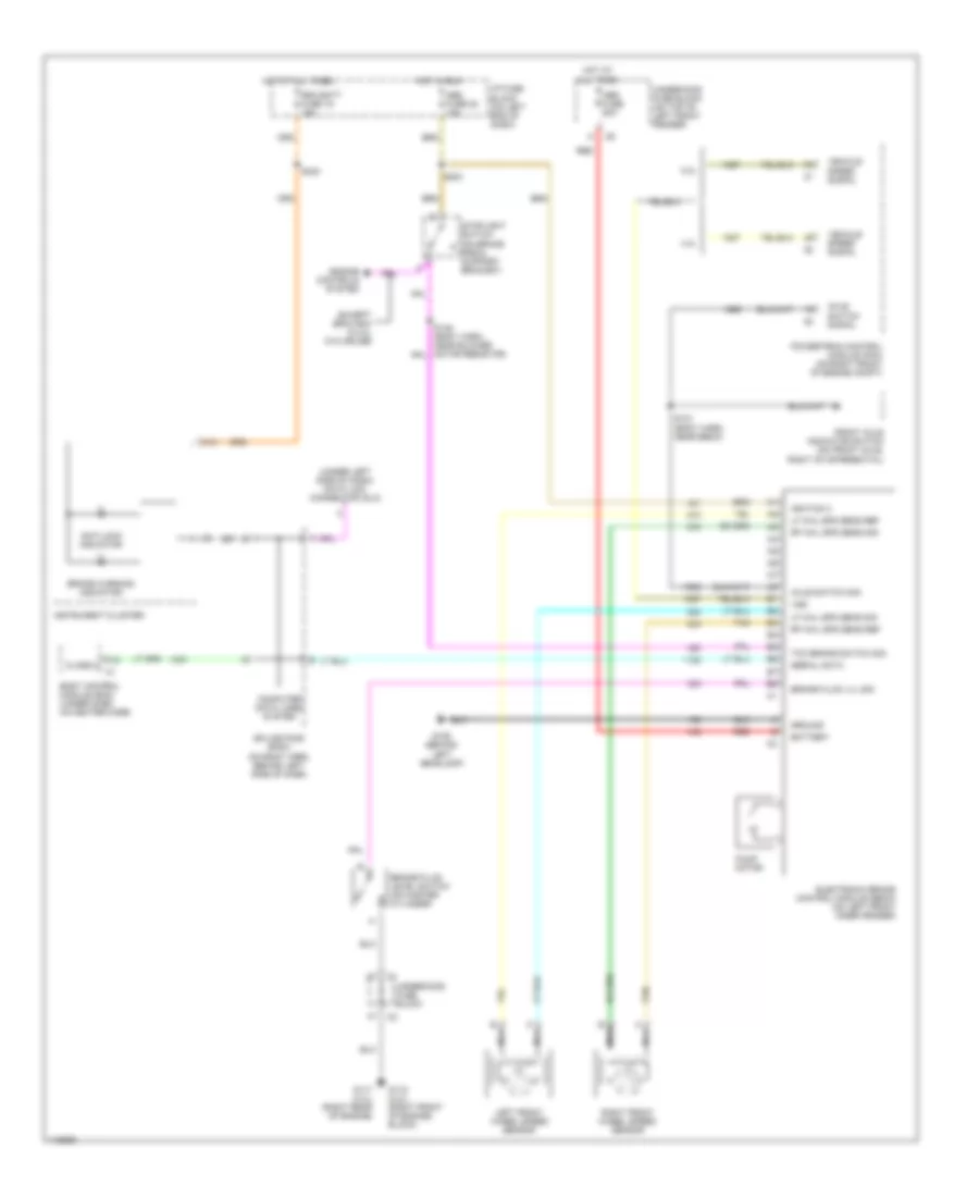
MALIBU
Anti-Lock Brakes Wiring Diagram (Malibu) for Chevrolet RV Cutaway G2001 3500
List of elements for Anti-Lock Brakes Wiring Diagram (Malibu) for Chevrolet RV Cutaway G2001 3500:
- (below left side of dash) powertrain control module (pcm)
- A10
- A11
- A12
- A3 c3
- A7 c3
- Abs fuse 50a
- Abs ign fuse 10a
- Antilock brake warning indicator
- B10
- B11
- B7 c2
- Battery
- Body control module (bcm) (below right side of dash)
- Brake pressure modulator valve
- Brake sw in
- Brake switch (on brake pedal support)
- C10
- C11
- C3 b2
- D2 c1
- Data clock control
- Data link connector (dlc) (below left side of dash)
- E3 c1
- Electronic brake control module (ebcm) (inside left front fender)
- F12
- G129 (on transaxle)
- Ground
- Hot at all times
- Hot in on or start
- Ignition
- Instrument cluster
- Left front wheel speed sensor
- Left i/p junction block
- Left i/p junction block (on left end of dash)
- Left rear wheel speed sensor
- Lf wheel spd (hi)
- Lf wheel spd (lo)
- Lr wheel spd (hi)
- Lr wheel spd (lo)
- Nca
- Pnk
- Pump motor
- Red
- Red brake warning indicator
- Rf wheel spd (hi)
- Rf wheel spd (lo)
- Right front wheel speed sensor
- Right i/p junction block (on right end of dash)
- Right rear wheel speed sensor
- Rr wheel spd (hi)
- Rr wheel spd (lo)
- Serial data
- Serial data receive
- Serial data signal
- Serial data transmit
- Sp103
- Sp301 (2000)
- Sp302 (2001)
- Spi clock
- Spi data receive
- Spi data transmit
- Stop lps fuse 15a
- Tan
- Underhood junction block (on left side of engine compt)
METRO
Anti-Lock Brakes Wiring Diagram (Metro) for Chevrolet RV Cutaway G2001 3500
List of elements for Anti-Lock Brakes Wiring Diagram (Metro) for Chevrolet RV Cutaway G2001 3500:
- (i/p harn, 1 cm from cluster breakout) s249
- (left kick panel) g200
- (main harn, 20 cm from bulkhead grommet) s223
- A10
- A11
- A12
- Abs active
- Abs active ind
- Abs control module (left side of dash)
- Abs enable
- Abs fuse 40a
- Abs ind
- Abs motor pack assembly
- B10
- B11
- B12
- Battery feed
- Brake ind
- Brake ind ctrl
- Brake signal
- Data link connector on board diagnostics ii (upper left side of dash)
- Def fuse 20a
- Electronic brake control relay (in relay box)
- Fuse box
- G100 (left front of engine compt)
- Ground
- Hazard fuse 15a
- Hot at all times
- Hot in on
- Hot in on or start
- Ig-coil fuse 15a
- Ignition power
- Instrument cluster
- Junction block
- Lamp driver relay (left side of dash)
- Lamp drvr rly
- Left front speed sensor
- Left rear speed sensor
- Lf motor
- Lf solenoid
- Lft frt motor
- Lft frt sens in
- Lft frt sol out
- Lft rr sens in
- Pnk
- Rear motor
- Rf motor
- Rf solenoid
- Right front speed sensor
- Right rear speed sensor
- Rt frt motor
- Rt frt sens in
- Rt frt sol out
- Rt rr sens in
- S124 (main harn, 5 cm from front abs solenoids breakout)
- S206 (main harn, 22 cm from stop lamp switch breakout)
- S208
- S215
- S242
- S251 (main harn, 5 cm from bulkhead grommet)
- Serial data
- Stop fuse 15a
- Stop lamp switch (top of brake pedal switch)
- Switched batt
MONTANA, SILHOUETTE & VENTURE
Anti-Lock Brakes Wiring Diagram (Montana, Silhouette & Venture) for Chevrolet RV Cutaway G2001 3500
List of elements for Anti-Lock Brakes Wiring Diagram (Montana, Silhouette & Venture) for Chevrolet RV Cutaway G2001 3500:
- (right side of dash, left of heater-a/c vent) g201
- A10
- A11
- Abs warning ind
- B10
- B11
- Battery
- Brake fluid level switch (on right side of brake fluid reservoir)
- Brake ind
- Brake pressure modulator valve
- C10
- C11
- Data link connector (dlc) (below steering column, on knee bolster)
- Delivered torque
- Desired torque
- Driver information center
- Electronic brake control module (ebcm) (at lower left side of engine compt)
- Fuse block (right side of dash)
- G133 (in engine compt, near starter solenoid)
- G201 (right side of dash, left of heater-a/c vent)
- Ground
- Hot at all times
- Hot in run, bulb test or start
- Ignition
- Instrument cluster
- Interior lights system
- Left front wheel spd (hi)
- Left front wheel spd (lo)
- Left front wheel speed sensor
- Left rear wheel spd (hi)
- Left rear wheel spd (lo)
- Left rear wheel speed sensor
- Multi-function switch
- Nca
- Pcm/abs fuse 10a
- Pnk
- Powertrain control module (pcm) (secured in air cleaner assembly)
- Pump motor
- Rear fog lamp/ tcs switch
- Red
- Right front wheel spd (hi)
- Right front wheel spd (lo)
- Right front wheel speed sensor
- Right rear wheel spd (hi)
- Right rear wheel spd (lo)
- Right rear wheel speed sensor
- S108
- S205
- S230
- S242
- Serial data sig
- Service traction system
- Splice pack sp205 (below steering column)
- Stop lamp sw out
- Stoplamp fuse 15a
- Stoplight switch (top of brake pedal support)
- Tan
- Trac off
- Traction active
- Traction ctrl on/off sig
- Underhood junction block
- Vent tube
PARK AVENUE
Anti-Lock Brakes Wiring Diagram (Park Avenue) for Chevrolet RV Cutaway G2001 3500
List of elements for Anti-Lock Brakes Wiring Diagram (Park Avenue) for Chevrolet RV Cutaway G2001 3500:
- (behind glove box) body control module (bcm)
- (body harn, near left kick panel)
- (engine harn, near lf wheel speed sensor breakout)
- (engine harn, near rf wheel speed sensor breakout)
- A1 c3
- A11 c2
- Abs 2 fuse 10a
- Abs fuse 10a
- Abs fuse 50a
- Abs ind lamp
- Abs ind sig
- Abs indicator
- B c6
- B1 c1
- B11
- B12
- B12 c2
- B13
- Battery
- Brake pressure modulator valve
- Computer data lines system
- Delivered torque output
- Driver information center (dic)
- E9 c3
- Electronic brake control module (ebcm) (on left front corner of engine compt)
- Exterior lights system
- F12 c3
- G102 (near wind- shield washer reservoir)
- G200 (left kick panel)
- Ground-module
- Ground-pump motor
- Hot at all times
- Hot in run
- I/p fuse block (behind glove box)
- Ignition 3
- Instrument cluster
- Lateral accelerometer
- Lateral accelerometer sensor (under left rear seat)
- Left front wheel speed sensor
- Left rear wheel speed sensor
- Lf wheel spd sens-ret
- Lf wheel spd sens-sig
- Lr wheel spd sens-ret
- Lr wheel spd sens-sig
- Nca
- Powertrain control module (pcm) (in air cleaner housing)
- Pump motor
- Rear fuse block (below right side of rear seat)
- Red
- Requested torque input
- Rf wheel spd sens-ret
- Rf wheel spd sens-sig
- Right front wheel speed sensor
- Right rear wheel speed sensor
- Rr wheel spd sens-ret
- Rr wheel spd sens-sig
- S111
- S112
- S198
- S199
- S220
- S221
- S299
- Sens feed-5v
- Sensor ret
- Serial data class 2
- Steering wheel pos
- Steering wheel position sensor (swps) (on base of steering column)
- Stop fuse 20a
- Stoplamp switch (on brake pedal support)
- Stoplight sw
- Tan
- Torque delivered
- Torque desired
- Trac ctrl sw
- Traction control switch
- Traction control system active
- Traction off indicator
- Underhood fuse block (left) (on right front of engine compt, near battery)
- Var effort steering
- Variable effort steering actuator (on power steering rack)
- Vent tube
- Yaw rate sens
- Yaw rate sensor (under rear shelf, behind lid hinge)
PRIZM
Anti-Lock Brakes Wiring Diagram (Prizm) for Chevrolet RV Cutaway G2001 3500
List of elements for Anti-Lock Brakes Wiring Diagram (Prizm) for Chevrolet RV Cutaway G2001 3500:
- (behind battery) g100
- (i/p harn, behind cluster) sp255
- 1132a
- 1132b
- Abs fuse 50a
- Abs ind ctrl
- Abs ind driver module
- Abs pump motor
- Battery
- Brake pressure modulator valve (bpmv) (left rear of engine compt)
- Brake sw
- Check conn
- Data link connector (dlc) obd ii (behind left side of dash)
- Ecu-ig fuse 10a
- Fuse & relay block 1 (left front of engine compt)
- G200 (behind left kick panel)
- Gauge fuse 10a
- Ground
- Hot at all times
- Hot in on & start
- Ignition
- Instrument cluster assembly
- Junction block 1 (behind left kick panel)
- Junction block 2 (behind left side of dash)
- Junction block 3 (behind center of dash)
- Left front solenoid valve
- Left front wheel speed sensor
- Left rear solenoid valve
- Left rear wheel speed sensor
- Lf spd sens
- Lr spd sens
- Multi- function alarm module
- Pnk
- Red
- Rf spd sens
- Right front solenoid valve
- Right front wheel speed sensor
- Right rear solenoid valve
- Right rear wheel speed sensor
- Rr spd sens
- Serial data
- Solid state
- Sp251 (cowl harn, near blower motor resistor branches)
- Sp254 (engine main harn, behind left kick panel)
- Sp256 (i/p harn, center of dash)
- Stop fuse 15a
- Stoplamp switch (on top of brake pedal bracket)
SATURN
Anti-Lock Brakes Wiring Diagram (Saturn LS, LS1, LS2, LW1 & LW2) for Chevrolet RV Cutaway G2001 3500
List of elements for Anti-Lock Brakes Wiring Diagram (Saturn LS, LS1, LS2, LW1 & LW2) for Chevrolet RV Cutaway G2001 3500:
- (2.2l)
- (3.0l)
- 2.2l engine
- 2x tach
- 3.0l engine
- A10
- A11
- Abs 1 fuse 30a
- Abs 2 fuse 30a
- Abs indicator
- Abs tt
- B10
- Bcm/ecm/ cruise/abs fuse 10a
- Body control module (bcm) (on top of glove box)
- Brake fuse 15a
- Brake pressure modulator valve (bpmv)
- Brake sw in
- Computer data lines system
- D11
- D12
- Data link connector (dlc) (lower left side of dash)
- Delivered torque in
- E10
- E11
- E12
- Electronic brake traction control module (ebtcm) (at left rear of engine compt)
- Engine control module (ecm) (on top right rear of engine)
- Exterior lights system
- F10
- Ground
- Hot at all times
- Hot in on or start
- Hot in run
- Ign 1
- Ign 1 fuse 10a
- Ign 3 fuse 10a
- Instrument cluster
- Led ctrl
- Left front wheel speed sensor
- Left instrument panel fuse block (lipfb)
- Left rear wheel speed sensor
- Lf speed sens
- Low trac tt
- Lr speed sens
- Nca
- Pnk
- Powertrain control module (pcm) (behind passenger side air bag)
- Pwr out
- Red
- Redundant ground
- Request torque
- Requested torque
- Rf spd sens
- Rf speed sens
- Rf speed sens out
- Right front wheel speed sensor
- Right heated seat/ traction off switch
- Right rear wheel speed sensor
- Rr speed sens
- Serial data
- Stoplight switch (on brake pedal bracket)
- Tan
- Torque delivered
- Trac ctrl tt
- Traction active indicator
- Traction control sw
- Traction off indicator
- Underhood fuse block (uhfb)
- Underhood fuse block (uhfb) (3.0l only)
- Wheel speed sensor drain wire j/b
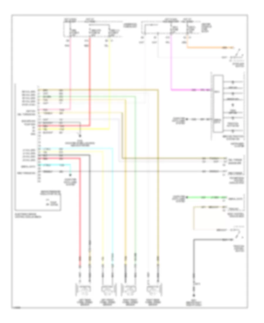
Anti-Lock Brakes Wiring Diagram (Saturn SC1, SC2, SL, SL1, SL2 & SW2) for Chevrolet RV Cutaway G2001 3500
List of elements for Anti-Lock Brakes Wiring Diagram (Saturn SC1, SC2, SL, SL1, SL2 & SW2) for Chevrolet RV Cutaway G2001 3500:
- (left front fender)
- A c6
- A11 c1
- Abs fuse 50a
- Abs indicator
- Batt
- Bo7
- Bo8
- Bo9
- Body control module (bcm) (behind left side of dash)
- Brake fuse 15a
- Brake pressure modulator valve (bpmv)
- Brake sw in
- Computer data lines system
- Data link connector (dlc) (under left side of dash)
- E10
- E2 c1
- Electronic brake/traction control module (ebtcm) (at left rear of engine compt)
- F10
- G100
- G102 (near base of left shock tower)
- Hot at all times
- Hot in run
- Hot in run or start
- I/p fuse block
- I/p splice pack 1 (behind left side of dash)
- I/p switch
- Ign
- Ign 1 fuse 10a
- Ign 3 fuse 10a
- Instrument cluster
- Left front wheel speed sensor
- Left rear wheel speed sensor
- Lf whl spd sens
- Lr whl spd sens
- Module sol grd
- Pmp mtr grd
- Pnk
- Powertrain control module (pcm) (between battery & power brake booster)
- Pwr out
- Red
- Rf whl spd sens
- Right front wheel speed sensor
- Right rear wheel speed sensor
- Rr whl spd sens
- Serial data
- Stoplight switch (on brake pedal bracket)
- Tan
- Trac sw in
- Traction active indicator
- Traction off ind
- Traction off sw
- Underhood fuse block
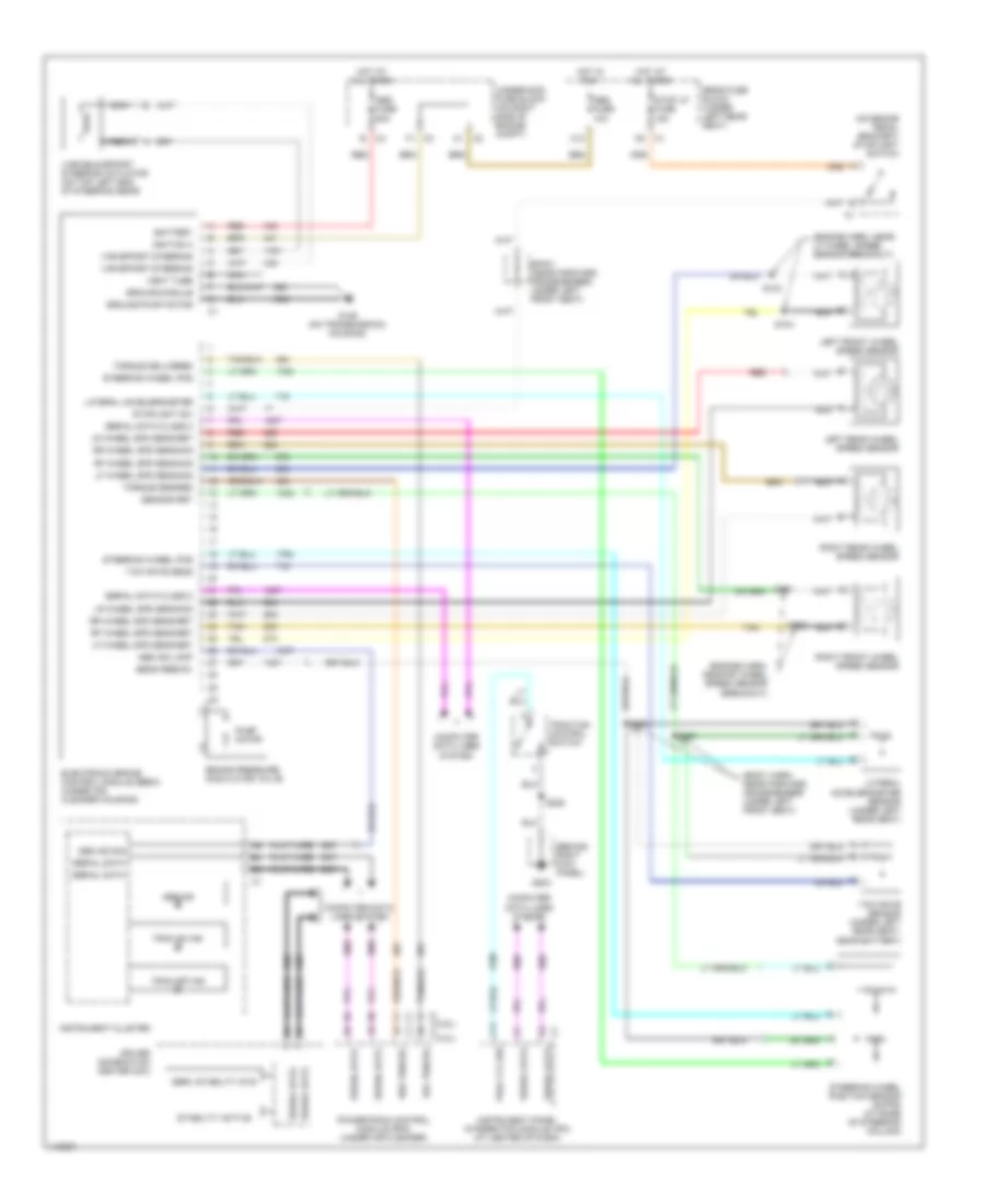
SEVILLE
Anti-Lock Brakes Wiring Diagram (Seville) for Chevrolet RV Cutaway G2001 3500
List of elements for Anti-Lock Brakes Wiring Diagram (Seville) for Chevrolet RV Cutaway G2001 3500:
- (behind center of dash) instrument panel integration module (ipm)
- (behind right rear seat back) continuously variable road sensing suspension module
- (body harn, near left rear door harness breakout)
- (engine harn, near camshaft position sensor connector)
- (engine harn, near coolant reservoir)
- (left rear of engine)
- Abs fuse 10a
- Abs fuse 50a
- Abs ind lamp
- Abs ind sig
- Abs indicator
- B c4
- Battery
- Brake pressure modulator valve
- Brake wear sens sig
- C1 c8
- C1 d4
- C11
- C12 c1
- Computer data lines system
- D14
- D15
- Delivered torque output
- Driver information center (dic)
- Electronic brake control module (ebcm) (on left front corner of engine compt)
- G114
- G300 (under left front seat)
- G404
- Ground-module
- Ground-pump motor
- Hot at all times
- Hot in run
- Ignition 3
- Instrument cluster
- J/b (left side of rear compt)
- Lateral accelerometer
- Lateral accelerometer sensor (under left rear seat)
- Left front brake pad wear sensor
- Left front wheel speed sensor
- Left normal force sig
- Left rear brake pad wear sensor
- Left rear wheel speed sensor
- Lf wheel spd sens-ret
- Lf wheel spd sens-sig
- Lr wheel spd sens-ret
- Lr wheel spd sens-sig
- Nca
- Powertrain control module (pcm) (below air cleaner)
- Pump motor
- Rear fuse block (under left rear seat)
- Red
- Requested torque input
- Rf wheel spd sens-ret
- Rf wheel spd sens-sig
- Right front brake pad wear sensor
- Right front wheel speed sensor
- Right normal force sig
- Right rear brake pad wear sensor
- Right rear wheel speed sensor
- Rr wheel spd sens-ret
- Rr wheel spd sens-sig
- S117
- S118
- S119
- S120
- S300
- S301
- S316
- Sens feed-5v
- Sensor ret
- Serial data class 2
- Sp302
- Steering wheel pos
- Steering wheel position
- Steering wheel position sensor (swps) (on base of steering column)
- Stop lamp/ btsi switch (near top of brake pedal)
- Stop lp fuse 15a
- Stoplight sw
- Strg wheel pos sens
- Tan
- Torque delivered
- Torque desired
- Trac ctrl sw
- Traction control indicator
- Traction control switch
- Traction off
- Underhood fuse block (on right side of engine compt)
- Var effort steering
- Variable effort steering actuator (on left side of power steering gear)
- Vent tube
- Yaw rate sens
- Yaw rate sensor (left side of rear compt)
SIERRA, SILVERADO, SUBURBAN, TAHOE & YUKON
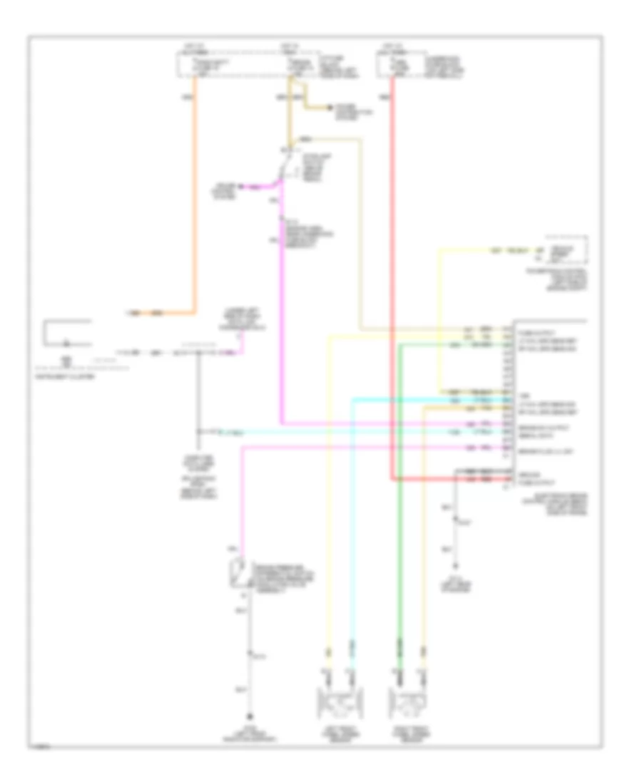
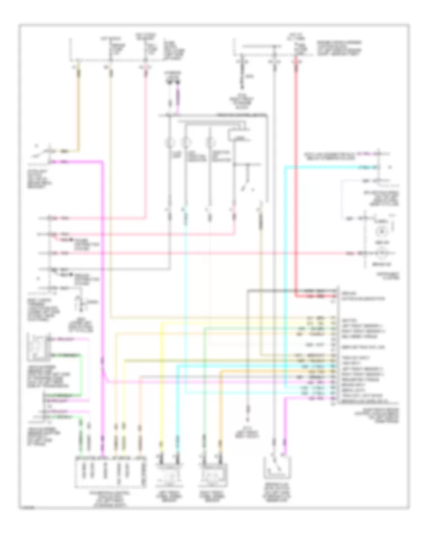
Anti-Lock Brakes Wiring Diagram (Sierra 1500/2500, Silverado 1500/2500, Suburban, Tahoe, Yukon & Yukon XL - With Traction Control) for Chevrolet RV Cutaway G2001 3500
List of elements for Anti-Lock Brakes Wiring Diagram (Sierra 1500/2500, Silverado 1500/2500, Suburban, Tahoe, Yukon & Yukon XL - With Traction Control) for Chevrolet RV Cutaway G2001 3500:
- A4 c1
- Abs fuse 60a
- Abs ind
- Body wiring harness junction block (under left side of dash, near kick panel)
- Brake fluid level sw in
- Brake fluid level switch (on left side of brake fluid reservoir)
- Brake fuse 10a
- Brake in
- Brake ind
- Brake input
- C8 a
- Data link connector (dlc) (below steering column)
- Del torque
- Delivered torque
- Electronic brake control module (ebcm) (on left side of inner frame)
- Engine wiring harness junction block (at left side of engine compt, near battery)
- F6 c3
- F7 c2
- Fuse block (on lower left side of dash)
- G113 (left front body mount)
- G132 (right front of engine block)
- G202 (upper left side of dash, at "a" pillar)
- Ground
- Ground distribution system
- Hot at all times
- Hot in run
- Hot in run or start
- Ign 1 fuse 10a
- Ignition
- Illum lamp
- Instrument cluster
- Interior lights system
- Left front sensor (+)
- Left front sensor (-)
- Left front wheel speed sensor
- Logic
- Low traction indicator
- Motor & solenoid pwr
- Nca
- Pnk
- Power distribution system
- Powertrain control module (pcm) (on left front of engine compt)
- Red
- Req torque
- Requested torque
- Right front sensor (+)
- Right front sensor (-)
- Right front wheel speed sensor
- S102
- Serial data
- Service trac cntl sig
- Sp203
- Splice pack sp203 (on top left side of dash, near "a" pillar)
- Stoplight switch (on top of brake pedal bracket)
- Tan
- Trac cntl active sig
- Trac sw input
- Traction control switch
- Traction off indicator
- Vehicle speed sensor (vss) (4wd: on top left side of transfer case) (2wd: on left rear side of transmission)
- Vehicle speed sensor adapter (4wd only) (on left side of trans)
- Vss high
- Vss input
- Vss low
- Vss out
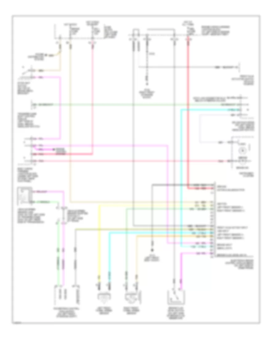
Anti-Lock Brakes Wiring Diagram (Sierra 1500/2500/2500HD, Silverado 1500/2500/2500HD, Suburban, Tahoe, Yukon & Yukon XL - Without Traction Control) for Chevrolet RV Cutaway G2001 3500
List of elements for Anti-Lock Brakes Wiring Diagram (Sierra 1500/2500/2500HD, Silverado 1500/2500/2500HD, Suburban, Tahoe, Yukon & Yukon XL - Without Traction Control) for Chevrolet RV Cutaway G2001 3500:
- A4 c1
- Abs fuse 60a
- Abs ind
- Body wiring harness junction block (under left side of dash, near kick panel)
- Brake fluid level sw in
- Brake fluid level switch (on left side of brake fluid reservoir)
- Brake fuse 10a
- Brake ind
- Brake input
- C8 a
- Data link connector (dlc) (below steering column)
- Electronic brake control module (ebcm) (on left side of inner frame)
- Engine control system
- Engine wiring harness junction block (at left side of engine compt, near battery)
- F6 c3
- F7 c2
- Front axle act/sw input
- Front axle actuator/ switch (on axle housing)
- Fuse block (on lower left side of dash)
- G113 (left front body mount)
- G132 (right front of engine block)
- Ground
- Hot at all times
- Hot in run
- Hot in run or start
- Ign 1 fuse 10a
- Ignition
- Instrument cluster
- Left front sensor (+)
- Left front sensor (-)
- Left front wheel speed sensor
- Logic
- Motor & solenoid pwr
- Nca
- Pnk
- Power distribution system
- Powertrain control module (pcm) (on left front of engine compt)
- Red
- Right front sensor (+)
- Right front sensor (-)
- Right front wheel speed sensor
- S102
- Serial data
- Splice pack sp205 (on left side of dash, behind headlamp switch)
- Stoplight switch (on top of brake pedal bracket)
- Tan
- Transfer case shift control module (left side of dash, behind headlamp switch)
- Vehicle speed sensor (vss) (4wd: on top left side of transfer case) (2wd: on left rear side of transmission)
- Vehicle speed sensor adapter (4wd only) (on left side of trans)
- Vss high
- Vss input
- Vss low
- Vss output
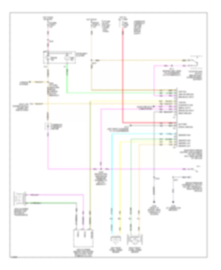
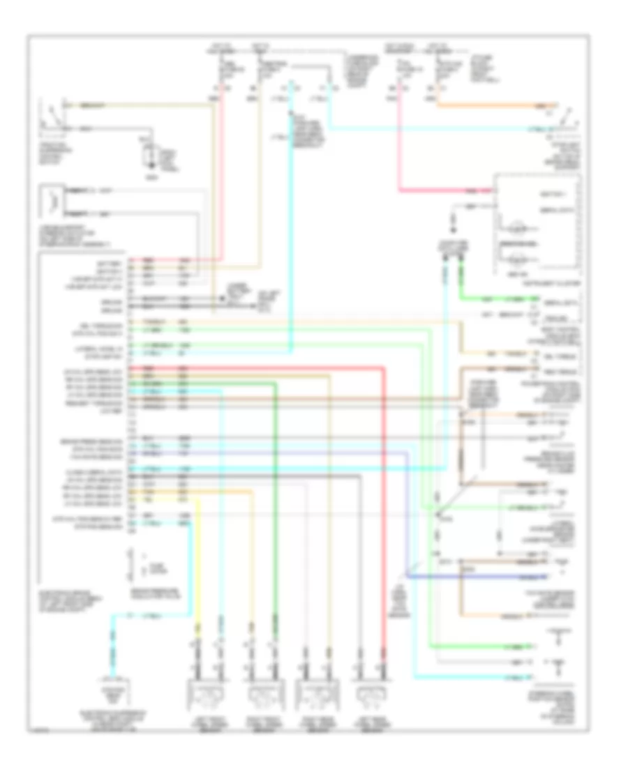
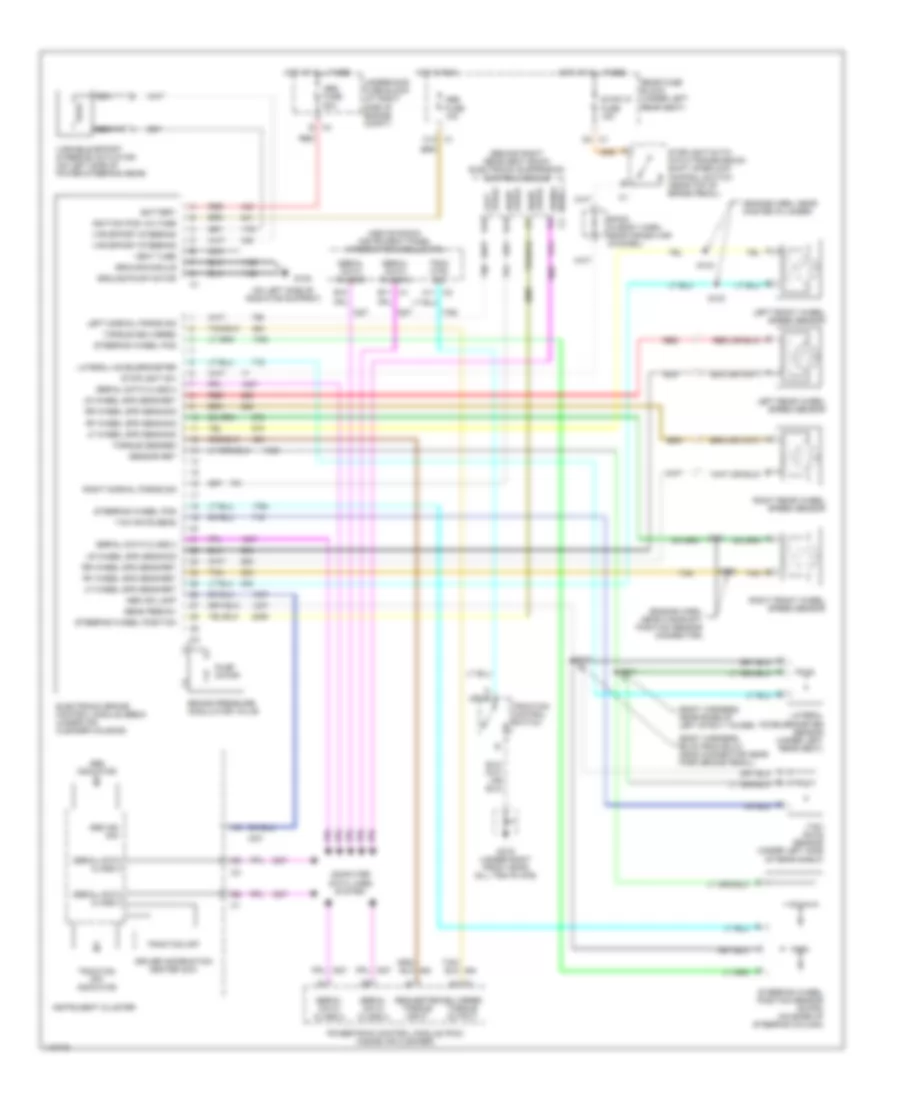
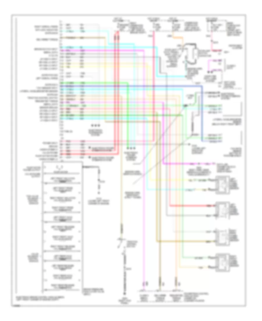
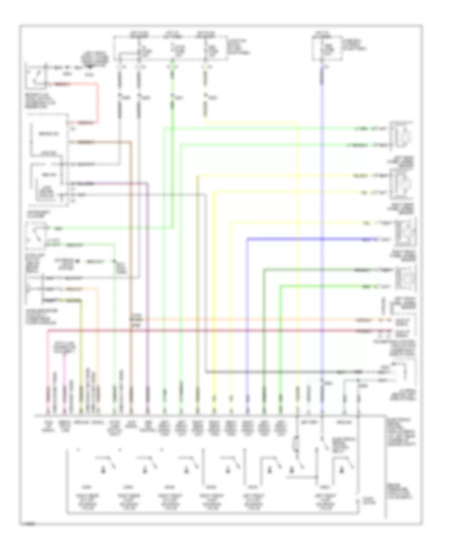
Anti-Lock Brakes Wiring Diagram (Sierra 3500 & Silverado 3500) for Chevrolet RV Cutaway G2001 3500
List of elements for Anti-Lock Brakes Wiring Diagram (Sierra 3500 & Silverado 3500) for Chevrolet RV Cutaway G2001 3500:
- (dlc) (below steering column)
- (engine harn, 20 cm into ebcm breakout)
- Abs fuse 60a
- Abs ind
- Abs ind failure cntl
- Abs serial data
- Axle sw signal
- Battery
- Brake fuse 18 10a
- Brake pres diff sw signal
- Brake pressure differential switch
- Brake warning ind
- Class 2 serial data
- Cruise control system
- Data link connector
- Diesel
- Drl module (under left side of dash)
- Electronic brake control module (ebcm) (on left side of inner frame)
- Engine controls system
- Engine wiring harness junction block (at left side of engine compt, near battery)
- Fuse block (on lower left side of dash)
- G117 (rear of right cyl head)
- G132 (back of engine block, below left cyl head)
- Gas
- Gauges fuse 4 10a
- Ground
- Hot at all times
- Hot in run
- Hot in run or start
- Ignition 3
- Instrument cluster
- Left front wheel speed sensor
- Lf whl sp sens low ref
- Lf whl spd sens signal
- Parking brake switch (part of park brake assembly)
- Pnk
- Powertrain control module (pcm) (on left front of engine compt)
- Red
- Rf whl sp sens low ref
- Rf whl spd sens signal
- Right front wheel speed sensor
- S107
- S150 (13 cm into ebcm breakout from engine harness)
- S152 (engine harn, 16.5 cm from evap purge valve breakout)
- S157
- S213
- S224 (cluster connector breakout, 12 cm from inflatable ip harness)
- S229 (w/a/t) (engine harn, near pcm)
- S229 (w/m/t) (i/p harn, near radio)
- Stoplight switch (on top of brake pedal bracket)
- Tan
- Tcc brake sw signal
- Transmissions system
- Vehicle speed sensor (vss) (on left side of transfer case)
- Vehicle speed sensor buffer
- Vehicle speed signal
- W/ drl
- W/o drl
TRACKER
Anti-Lock Brakes Wiring Diagram (Tracker) for Chevrolet RV Cutaway G2001 3500
List of elements for Anti-Lock Brakes Wiring Diagram (Tracker) for Chevrolet RV Cutaway G2001 3500:
- (1.6l/2.0l)
- (2.5l)
- (left front shock tower, near washer reservoir)
- (m/t) (a/t)
- (main harn)
- (pin b8 not used)
- (pins b10-b11 not used)
- (pins b2-b6 not used)
- (pins c1-c5 not used)
- (pins c8-c11 not used)
- 4wd ind
- 4wd signal
- A10
- A11
- Abs fuse 50a
- Abs ind
- Abs ind control
- Accelerometer (4wd only) (under rear floor console)
- Battery
- Brake fluid level switch (on brake fluid reservoir)
- Brake ind
- Brake pressure modulator valve (bpmv)
- Data link connector (dlc) obd ii
- Def fuse 15a
- Electronic brake control module (ebcm) (at left rear corner of engine compt)
- Electronic brake control relay
- Exterior lights system
- Fuse box (in front of battery)
- G102
- G202
- Ground
- Hot at all times
- Hot in on or start
- Idle up signal
- Ig fuse 20a
- Instrument cluster
- J/c sp200 (behind left side of dash)
- Junction block (in left kick panel)
- Lamp driver module
- Left front inlet solenoid valve
- Left front outlet solenoid valve
- Left front signal high
- Left front signal low
- Left front wheel speed sensor
- Left rear wheel speed sensor
- Nca
- Powertrain control module (pcm) (under right side of dash)
- Pump motor
- Right front inlet solenoid valve
- Right front outlet solenoid valve
- Right front signal high
- Right front signal low
- Right front wheel speed sensor
- Right rear inlet solenoid valve
- Right rear outlet solenoid valve
- Right rear signal high
- Right rear signal low
- Right rear wheel speed sensor
- S202
- S203
- S205
- S213 (main harn)
- S241
- S248
- S250
- S264
- S265
- S266
- Serial data line
- Signal
- Stop fuse 15a
- Stop- lamp switch input
- Stoplamp switch (above brake pedal)

 Čeština
 Deutsch
 Ελληνικά
 English
 English
 Español
 Suomi
Suomi Français
 Français
 עברית
עברית Hrvatski
 Magyar
 Italiano
 日本語
日本語 한국어
한국어 Nederlands
 Polski
 Português
 Português
 Română
 Русский
 Slovenčina
 Slovenščina
 Svenska
 Türkçe
 中文 (中国)