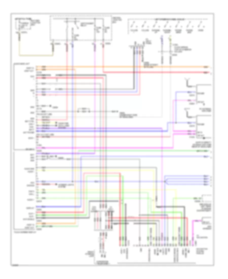
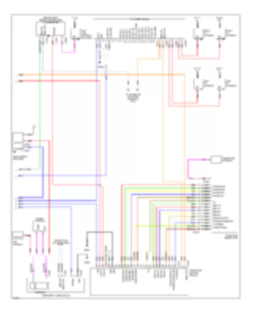
AIR CONDITIONING
Automatic A/C Wiring Diagram, with TSD for Land Rover Discovery 3 2006
 https://portal-diagnostov.com/license.html
Automotive Electricians Portal FZCO
Automotive Electricians Portal FZCO
https://portal-diagnostov.com/license.html
https://portal-diagnostov.com/license.html
Automotive Electricians Portal FZCO
Automotive Electricians Portal FZCO
List of elements for Automatic A/C Wiring Diagram, with TSD for Land Rover Discovery 3 2006:
- (left side of engine compt) engine control module (ecm)
- A/c
- Air temperature mode motor (behind left rear trim panel)
- Ambient air temperature sensor (front of engine compt)
- Automatic temperature control module
- Battery junction box
- Blower relay
- C0557 (left front wheel arch liner)
- C0570l
- C0580
- C0582
- C0634
- C0635l
- C1629
- C1630
- C2606
- C2629
- C2655
- Can +
- Can -
- Can h out
- Can high +
- Can high -
- Can l out
- Can med +
- Can med -
- Central junction box
- Computer data lines system
- Coolant temp
- E-box cooling fan (right rear of engine compt)
- E-box fan
- Ecm power
- Engine coolant temperature (ect) sensor (top of engine)
- Evaporator sensor (on hvac unit)
- Face/feet air distribution door motor (on hvac unit)
- Front blower motor (under right side of dash)
- Front blower motor control unit (on front blower motor assembly)
- Fuse 10a
- Fuse link 12 40a
- Generic electronic module
- Gnd
- Hfs
- Hot at all times
- Hot w/ engine control module relay energized
- Hrw
- Instrument cluster
- Intake air door motor
- Rear
- Recirc
- Red
- Refrigerant pressure sensor (left side of engine compt)
- Refrigerant solenoid valve (left side of engine)
- Screen air distribution door motor (on hvac unit)
- Seat l
- Seat r
- Sen gnd 6
- Sig gnd
- V out
Automatic A/C Wiring Diagram, without TSD for Land Rover Discovery 3 2006
List of elements for Automatic A/C Wiring Diagram, without TSD for Land Rover Discovery 3 2006:
- (left side of engine compt) engine control module (ecm)
- 12v
- Ambient air temperature sensor (front of engine compt)
- Auto
- Automatic temperature control module
- Battery junction box
- Blower
- Blower relay
- C0557 (left front wheel arch liner)
- C0560 (right headlight)
- C0570l
- C0580
- C0582
- C0634
- C0635l
- C1629
- C1630
- C2606
- C2629
- C2655
- Can +
- Can -
- Can h out
- Can high +
- Can high -
- Can l out
- Can med +
- Can med -
- Central junction box
- Computer data lines system
- Coolant temp
- Defrost
- Display
- E-box cooling fan (right rear of engine compt)
- E-box fan
- Ecm power
- Econ
- Engine coolant temperature (ect) sensor (top of engine)
- Evaporator sensor (on hvac unit)
- Face/feet air distribution door motor (on hvac unit)
- Front blower motor (under right side of dash)
- Front blower motor control unit (on front blower motor assembly)
- Fuse 10a
- Fuse link 12 40a
- Generic electronic module
- Gnd
- Hc/co
- Heater coolant temperature sensor
- Hfs
- Hot at all times
- Hot w/ engine control module relay energized
- Hrw
- Humidity temperature sensor
- Instrument cluster
- Intake air door motor
- Left air temperature door motor (on hvac unit)
- Nox
- Off
- Out
- Pollution sensor
- Rear
- Rear a/c circuit
- Recirc
- Red
- Refrigerant pressure sensor (left side of engine compt)
- Refrigerant solenoid valve (left side of engine)
- Right air temperature door motor (on hvac unit)
- Screen air distribution door motor (on hvac unit)
- Seat l
- Seat r
- Seats system (heated seat circuit)
- Sen gnd 6
- Sig gnd
- Sunlight sensor (top center of dash)
- Temp l
- Temp r
- Thr
- V out
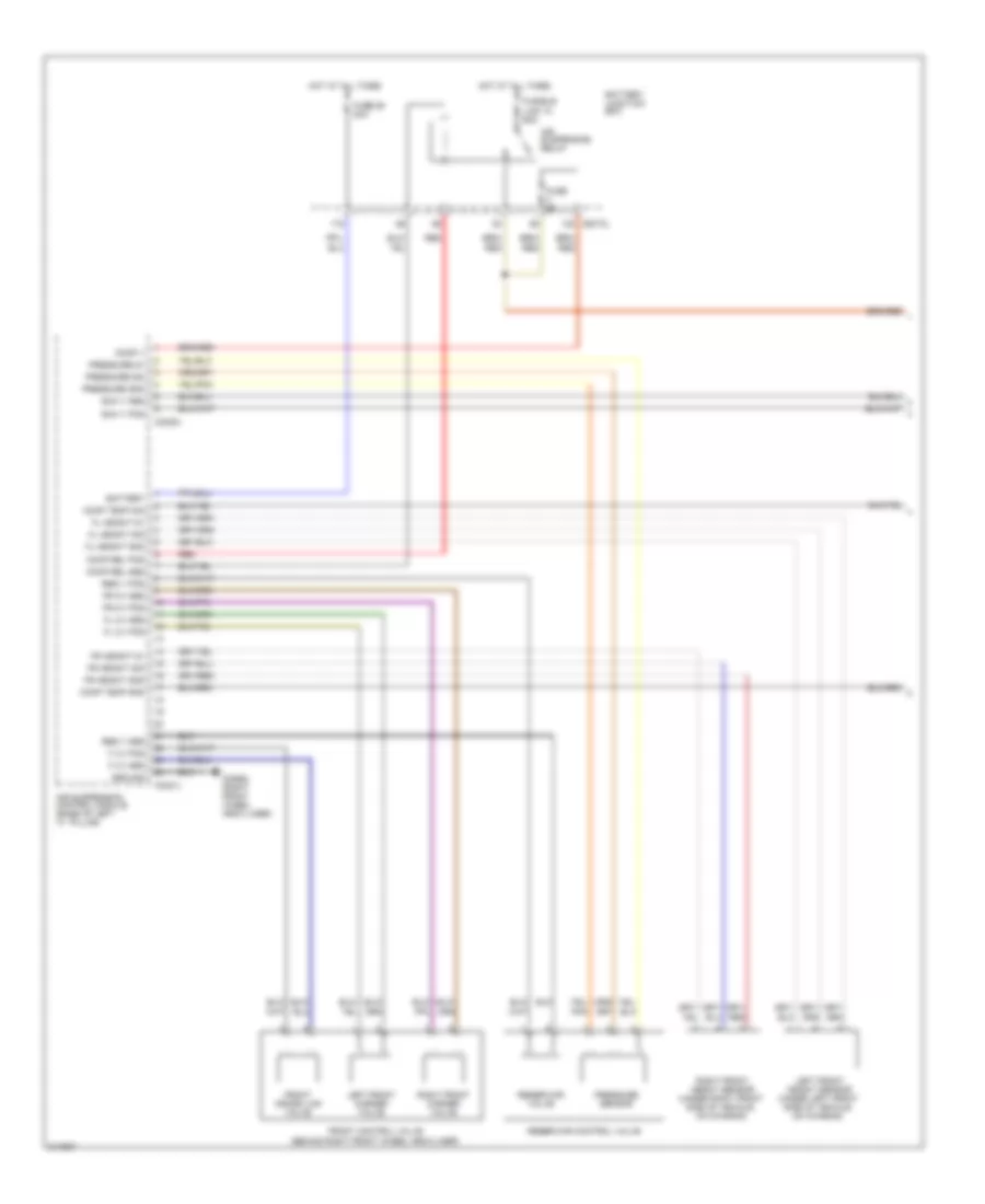
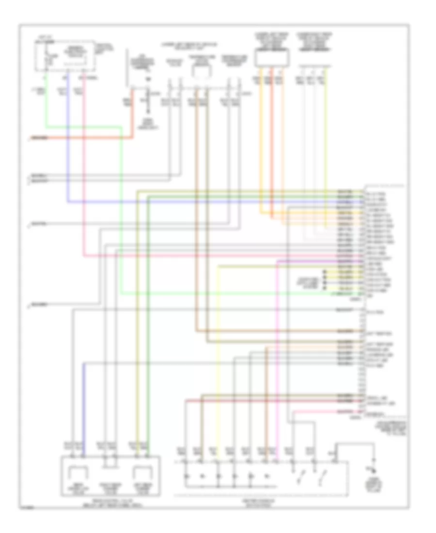
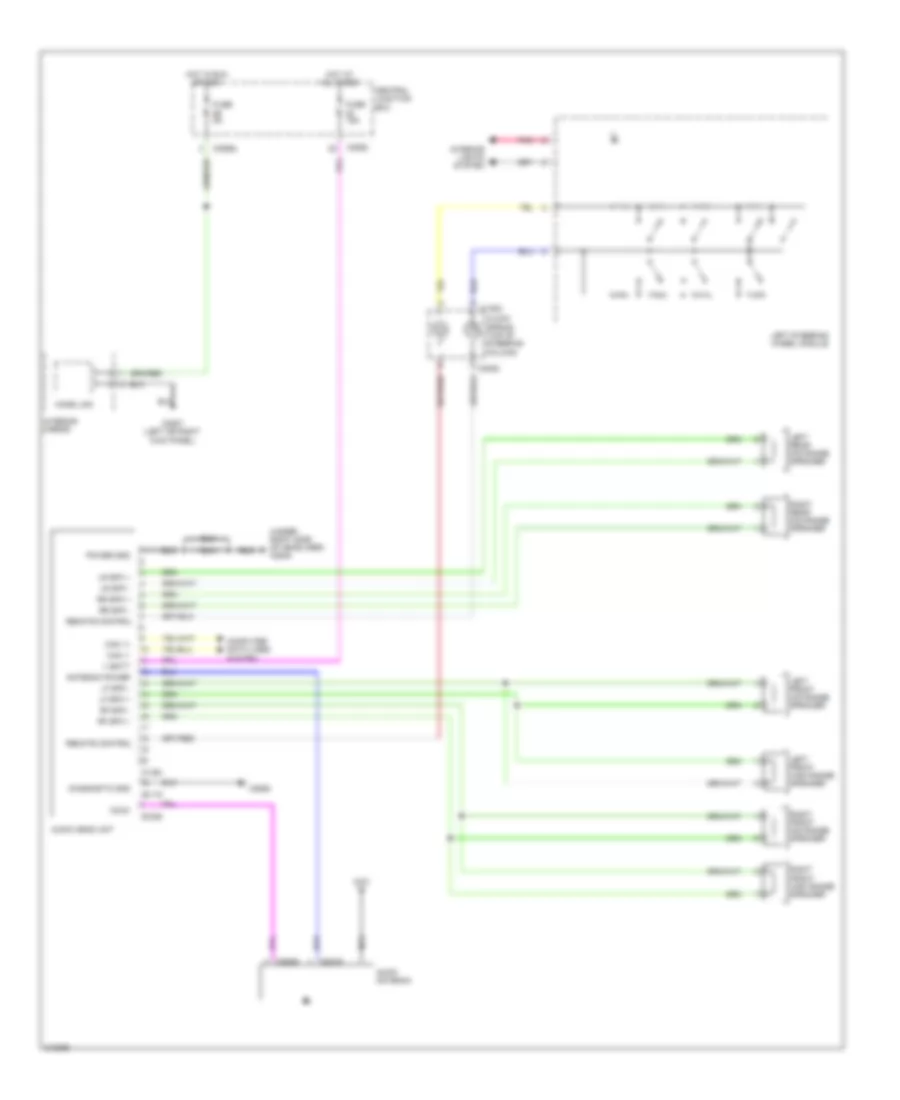
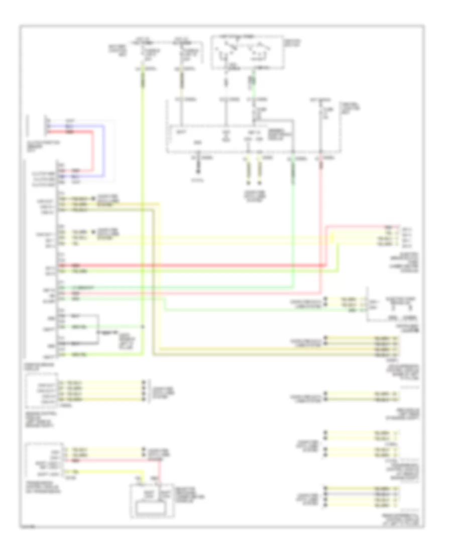
Rear A/C Wiring Diagram for Land Rover Discovery 3 2006
List of elements for Rear A/C Wiring Diagram for Land Rover Discovery 3 2006:
- (base of left "d" pillar)
- (not used)
- (right "a" pillar) c0811
- 12v
- Air distribution mode motor (behind left rear trim panel)
- Air off sensor
- Air temperature mode motor (behind left rear trim panel)
- Automatic temperature control module
- Battery junction box
- C0570l
- C0582
- C0585l
- C1629
- C1969
- C2598 (base of right "b" pillar)
- C2700 (base of left "d" pillar)
- Central junction box
- Cool box
- Fuse 10a
- Fuse 30a
- Gnd
- Hot at all times
- Line bus
- Magnetic valve
- Pollution sensor
- Power
- Rear automatic temperature control module
- Rear blower control unit (on rear blower motor assembly)
- Rear blower motor
- Rear blower relay
- Red
ANTI-LOCK BRAKES
Anti Lock Brake Wiring Diagram for Land Rover Discovery 3 2006
List of elements for Anti Lock Brake Wiring Diagram for Land Rover Discovery 3 2006:
- (right front wheel arch liner) c2603
- Abs ind
- Abs module (left rear of engine compt)
- Afs ecu
- Air suspension control module (base of left "a" pillar)
- Battery junction box
- Bla
- Bls
- C0040
- C0582 red
- C0867l
- C2114
- C2627 (right "a" pillar)
- Can m
- Can p
- Can-h
- Can-l
- Center console switch pack
- Center facia switch pack
- Central junction box
- Computer data lines system
- Diagnostic socket (under left side of dash)
- Dpfl
- Dpfr
- Dprl
- Dprr
- Drsr
- Drss
- Drst
- Dsfl
- Dsfr
- Dsrl
- Dsrr
- Exterior lights system
- Fuse 15a
- Fuse 25a
- Fuse 5a
- Fuse link 9 40a
- Gnd
- Hdc sw
- Hill descent relay
- Hot at all times
- Hot in run
- Ign
- Instrument cluster
- K-line
- Left front wheel speed sensor (left front wheelwell)
- Left rear wheel speed sensor (below left rear wheelwell)
- M gnd
- Mdo-2
- Navigation system module
- Nca
- Red
- Reset
- Right front wheel speed sensor (right front wheelwell)
- Right rear wheel speed sensor (below right rear wheelwell)
- Sgnd
- Sin 1
- Sot 1
- Speed control module
- Steering angle sensor (on underside of steering column)
- Stop lamp switch
- Tcsaus
- Ubmr
- Ubvr
- Vso
- Yaw rate sensor (under center console)
Terrain Response Wiring Diagram for Land Rover Discovery 3 2006
List of elements for Terrain Response Wiring Diagram for Land Rover Discovery 3 2006:
- Abs module (left rear of engine compt)
- Air suspension control module (base of left "a" pillar)
- C0583l
- C0635l
- C0867l
- C1319l
- C1854
- C2598 (base of right "b" pillar)
- Can h
- Can l
- Center console switch pack
- Central junction box
- Computer data lines system
- Engine control module (left side of engine compt)
- Fuse 5a
- Gnd
- Hot in run
- Ign
- Instrument cluster system
- Parking brake module
- Rear differential control module (if equipped) (at left "c" pillar)
- Red
- Terrain optimization switch
- Transfer box control module (at rear of engine compt)
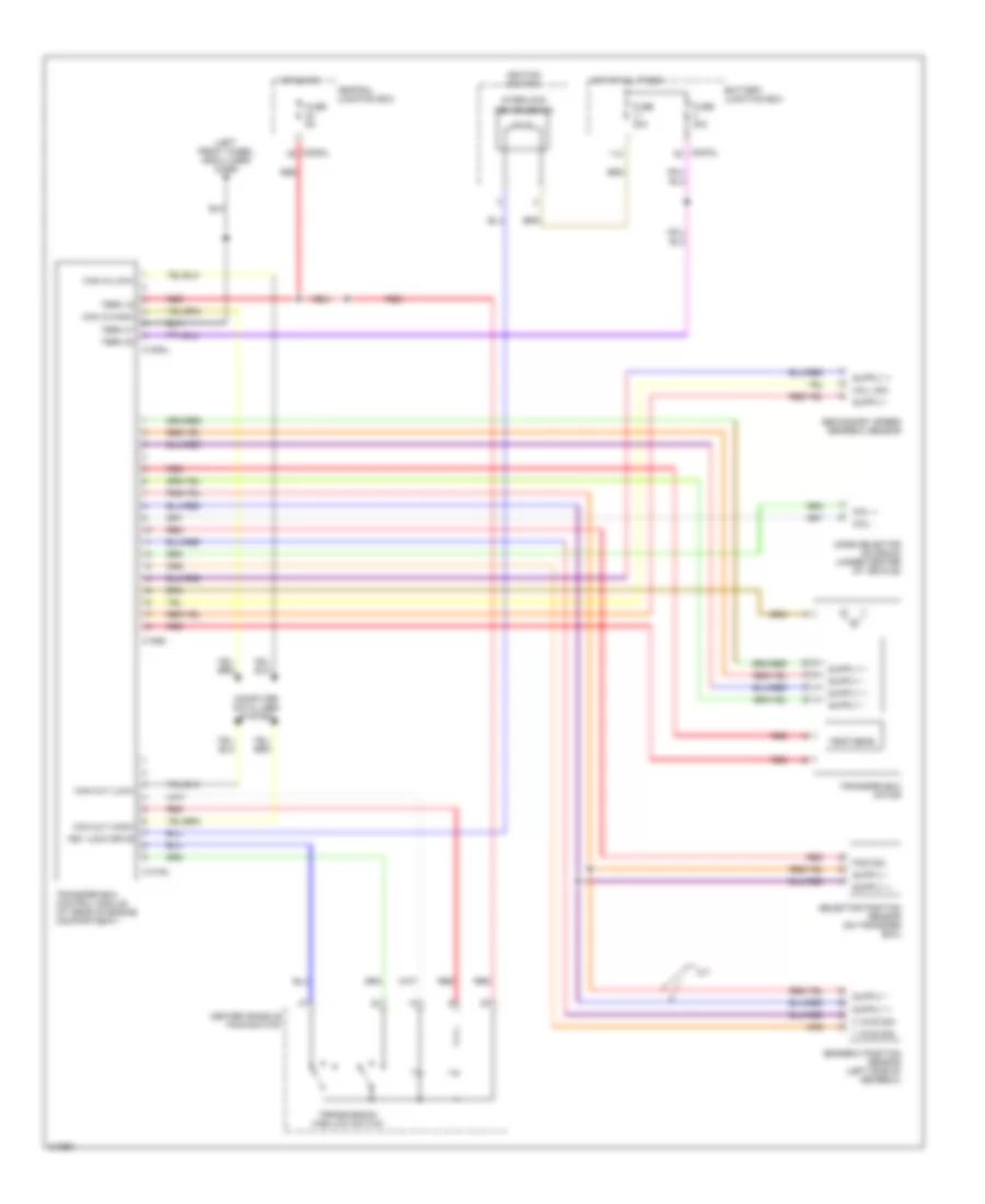
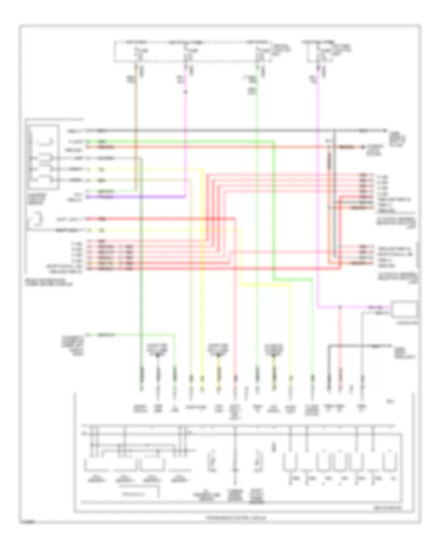
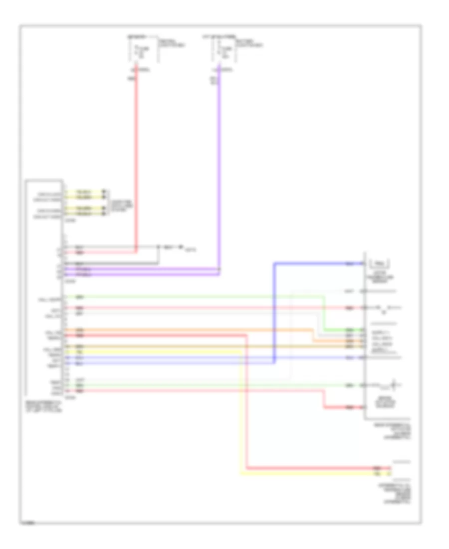
- Transmission control module (on transmission)
ANTI-THEFT
Anti-theft Wiring Diagram, Active for Land Rover Discovery 3 2006
List of elements for Anti-theft Wiring Diagram, Active for Land Rover Discovery 3 2006:
- (center of headliner) radio frequency receiver
- (left front wheel arch liner) c2601
- (not used)
- (under roof console) volumetric sensor
- 13 pin
- 50a
- 7 pin
- Alarm horn
- Alarm led
- Anti-theft alarm warning ind
- Aux
- Batt
- Battery backed up alarm sounder
- Battery junction box
- Bbs lin
- Bonnet ajar
- C0561 (right headlamp)
- C0561 (right headlight)
- C0564 (left front of engine compt)
- C0565
- C0570l
- C0580
- C0582
- C0583l
- C0584l
- C0585l
- C0586l
- C0809 (base of right "b" pillar)
- C0811
- C1355 (base of right "d" pillar)
- C1413
- C1964
- C1970
- C2565 (left "c" pillar)
- C2568 (base of left "d" pillar)
- C2920
- C2922 (base of left "d" pillar)
- Can +
- Can -
- Central junction box
- Computer data lines system
- Crank
- Driver door ajar sw
- Driver door central locking motor
- Driver door switch
- Fuse 12 15a
- Fuse 40 5a
- Fuse 5a
- Fuse 60 5a
- Fuse link 17
- Generic electronoc module
- Gnd
- Hood ajar switch (at right rear of engine compt)
- Horn relay
- Hot at all times
- Ign
- Ignition switch
- Instrument cluster
- Key in
- Key lock
- Key unlock
- Key-in
- Left front side repeater lamp
- Left headlamp
- Left horn
- Left ind o/p
- Left indi- cator fet
- Left rear door central locking motor (at rear of left door)
- Left rear door switch
- Left stop lamp
- Left trailer ind o/p
- Left trailer indicator fet
- Lf in
- Lf out
- Pass door ajar sw
- Pass door switch
- Passenger door central locking motor (at rear of front passenger's door)
- Passive coil
- Pick up trailer
- Red
- Rf in
- Right front side repeater lamp
- Right headlamp
- Right horn
- Right ind o/p
- Right indi- cator fet
- Right rear door central locking motor
- Right rear door switch
- Right stop lamp
- Right trailer ind o/p
- Right trailer indi- cator fet
- Rlh ajar sw
- Rrh ajar sw
- Tail door open switch
- Tail- gate ajar
- Turn signal ind/hazard flasher lamp
- Upper tailgate cdl motor
- Valu- metric arm
- Valu- metric power
- Valu- metric trigger
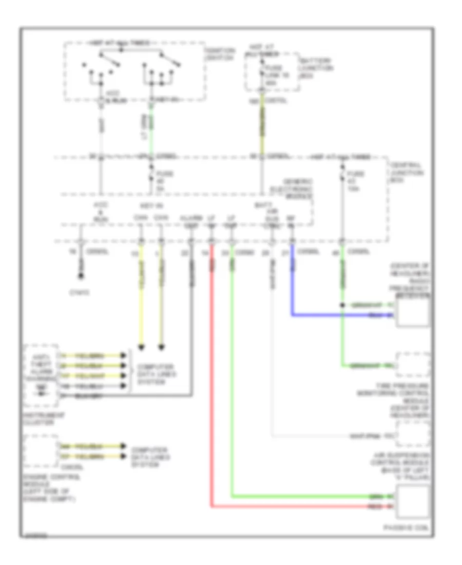
Anti-theft Wiring Diagram, Passive for Land Rover Discovery 3 2006
List of elements for Anti-theft Wiring Diagram, Passive for Land Rover Discovery 3 2006:
- (center of headliner) radio frequency receiver
- Acc & run
- Air sus ctrl
- Air suspension control module (base of left "a" pillar)
- Alarm led
- Anti- theft alarm warning ind
- Batt
- Battery junction box
- C0570l
- C0580
- C0582
- C0583l
- C0585l
- C0586l
- C0635l
- C1413
- Can +
- Can -
- Central junction box
- Computer data lines system
- Engine control module (left side of engine compt)
- Fuse 10a
- Fuse 5a
- Fuse link 16 40a
- Generic electronic module
- Hot at all times
- Ignition switch
- Instrument cluster
- Key in
- Key-in
- Lf in
- Lf out
- Passive coil
- Red
- Rf in
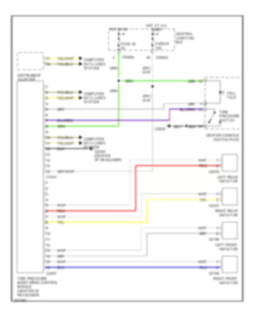
- Tire pressure monitoring control module (center of headliner)
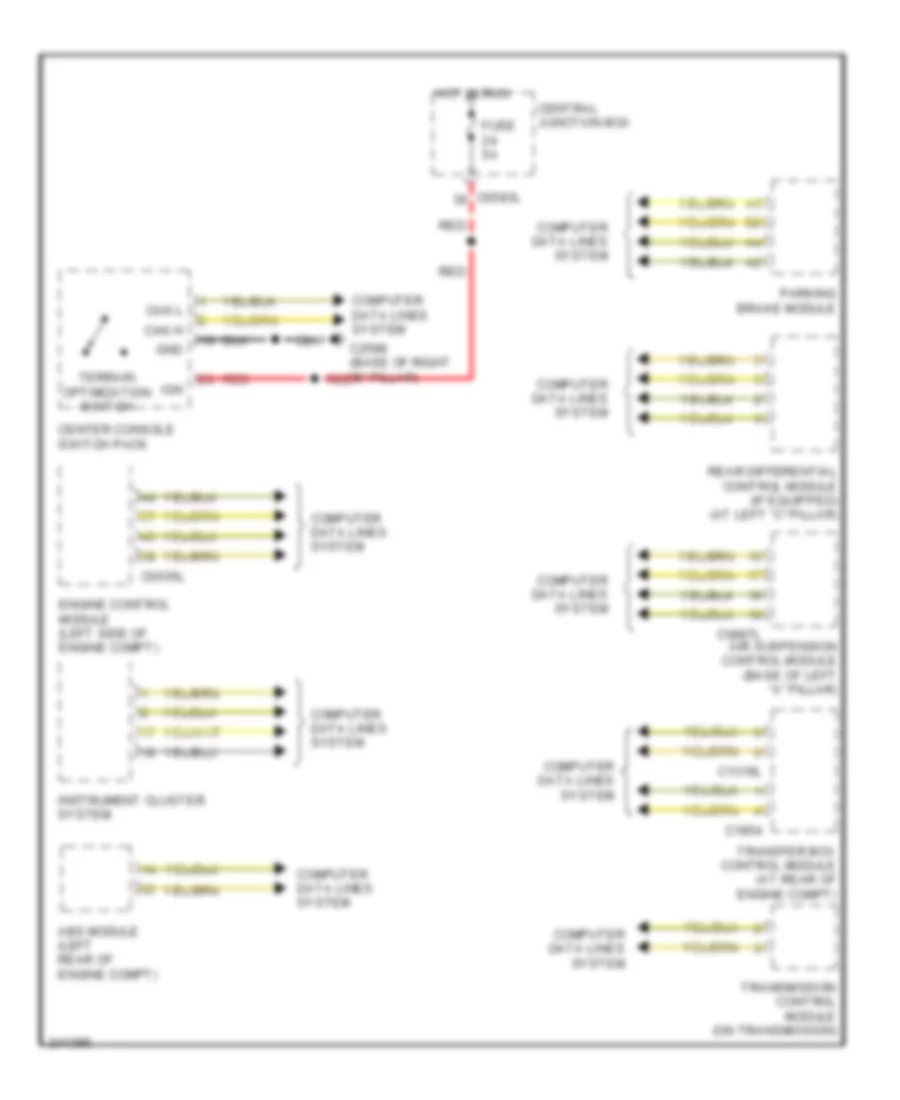
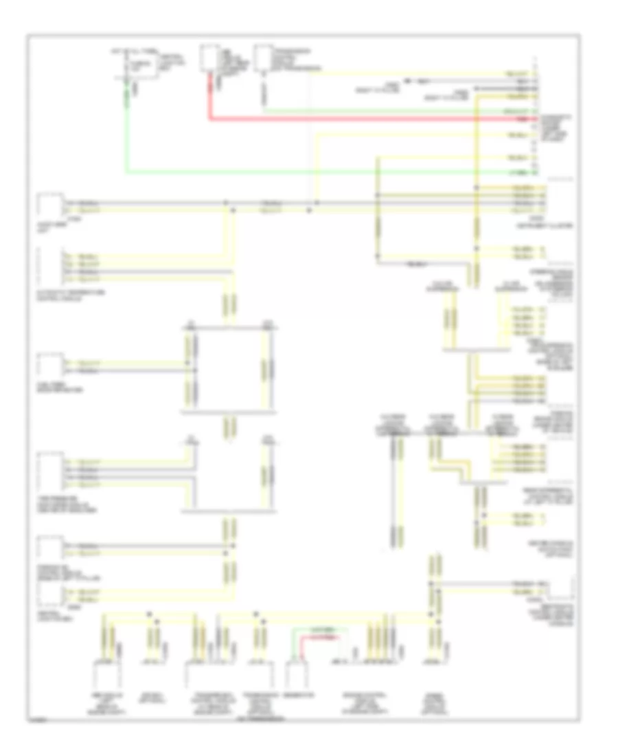
COMPUTER DATA LINES
Computer Data Lines Wiring Diagram for Land Rover Discovery 3 2006
List of elements for Computer Data Lines Wiring Diagram for Land Rover Discovery 3 2006:
- Abs module (left rear of engine compt)
- Abs module (left rear of engine compt) c0506l
- Afs ecu (optional)
- Air suspension control module (optional) (base of left "a" pillar)
- Audio head unit
- Automatic temperature control module
- C0230
- C0506l
- C0580
- C0582
- C0867l
- C1319l
- C1354
- C1854l
- C2145l
- C2193l
- C2627 (right "a" pillar)
- C2628 (right "a" pillar)
- C3223l
- C634
- C635l
- Center console switch pack (optional)
- Central junction box
- Diagnostic
- Engine control module (left side of engine compt)
- Fuel fired booster heater
- Fuse 63 10a
- Generator
- Hot at all times
- Instrument cluster
- Of dash)
- Parking aid control module (base of left "c" pillar)
- Parking brake module (under center of vehicle)
- Rear differential control module (at left "c" pillar)
- Red
- Restraints control module (under center console)
- Socket (under left side
- Speed control module (optional)
- Steering angle sensor (on underside of steering column)
- Tire pressure monitoring module (center of headliner)
- Transfer box control module (at rear of engine compt)
- Transmission control module (on transmission)
- Transmission control module (optional) (on transmission)
- W/ air suspension
- W/ fbh
- W/ rear locking differential w/ terrain
- W/ tpms
- W/o air suspension
- W/o fbh
- W/o rear locking differential w/ terrain
- W/o rear locking differential w/o terrain
- W/o tpms
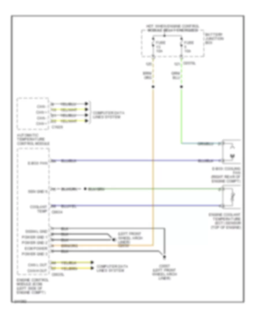
COOLING FAN
Cooling Fan Wiring Diagram for Land Rover Discovery 3 2006
List of elements for Cooling Fan Wiring Diagram for Land Rover Discovery 3 2006:
- (left front wheel arch liner) c2650
- Automatic temperature control module
- Battery junction box
- C0557 (left front wheel arch liner)
- C0570l
- C0635l
- C1629
- Can +
- Can -
- Can h out
- Can l out
- Computer data lines system
- Coolant temp c0634
- E-box cooling fan (right rear of engine compt)
- E-box fan
- Ecm power
- Engine control module (ecm) (left side of engine compt)
- Engine coolant temperature (ect) sensor (top of engine)
- Fuse 10a
- Hot when engine control module relay energized
- Power gnd 1
- Power gnd 2
- Power gnd 3
- Sen gnd 6
- Signal gnd
CRUISE CONTROL
Cruise Control Wiring Diagram for Land Rover Discovery 3 2006
List of elements for Cruise Control Wiring Diagram for Land Rover Discovery 3 2006:
- 15a
- 4.0l
- 4.4l
- 5v ref 3
- All times
- C0082
- C0582
- C0583l
- C0587l
- C0634
- C0635l
- C1254
- C2627 (right "a" pillar)
- Can h in
- Can h out
- Can high +
- Can high -
- Can l in
- Can l out
- Can med +
- Can med -
- Central junction box
- Clock spring (top of steering column)
- Computer data lines system
- Cruise sw +
- Driver air bag
- Electric throttle unit (center rear of engine)
- Engine control module (ecm) (left side of engine compt)
- Exterior lights system
- Fuse 15
- Fuse 25
- Fuse 39
- Horns system
- Hot at
- Hot in
- Ign (run)
- Instrument cluster
- Interior lights system
- Left steering wheel module
- Pnk
- Red
- Right steering wheel module
- Sensor gnd 3
- Sound systems
- Stop lamp switch
- Throttle +
- Throttle -
- Tps1
- Tps2
- V batt
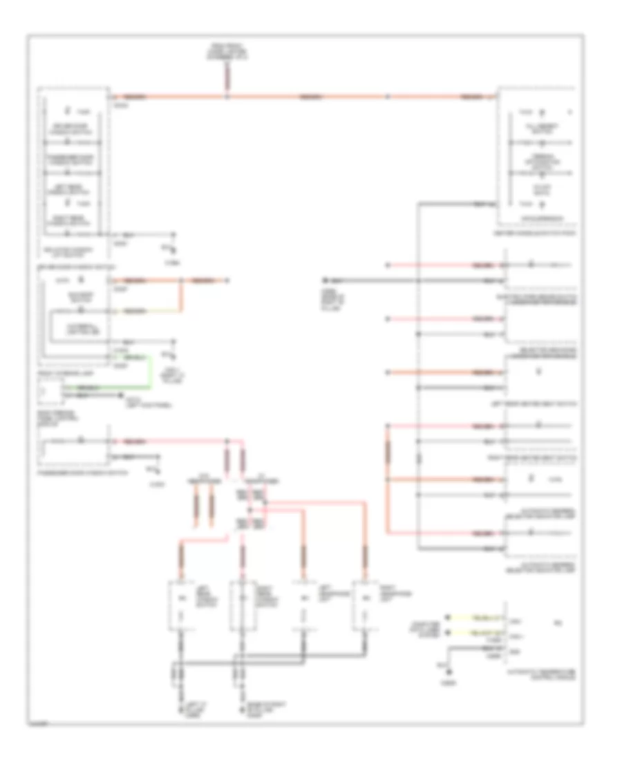
DEFOGGERS
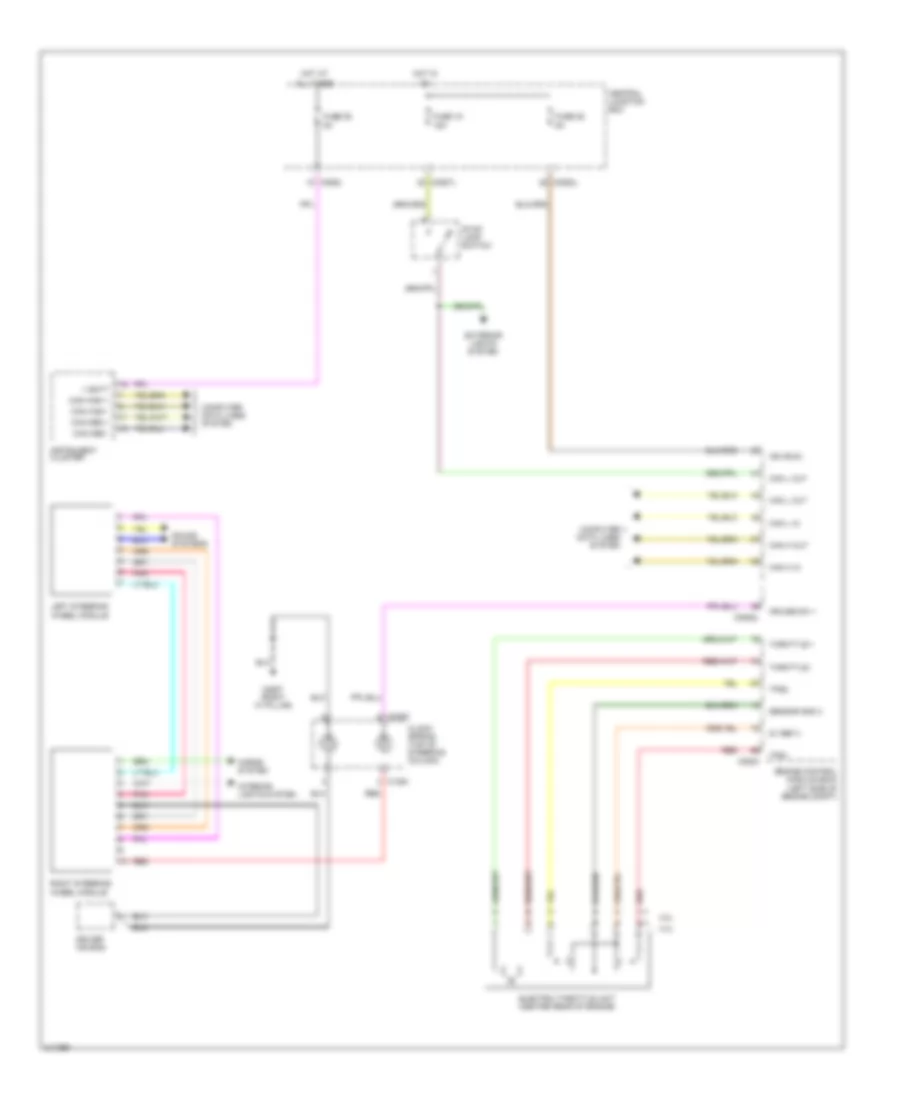
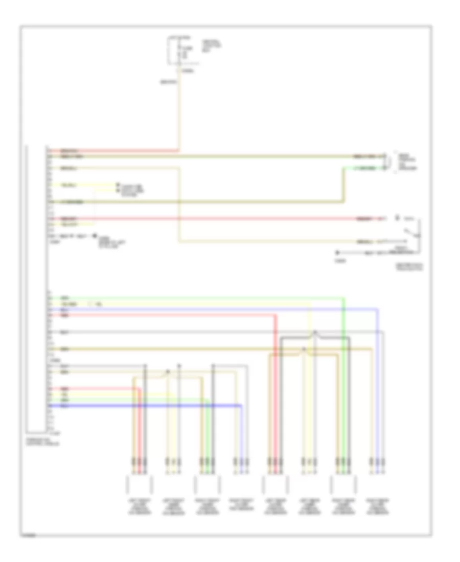
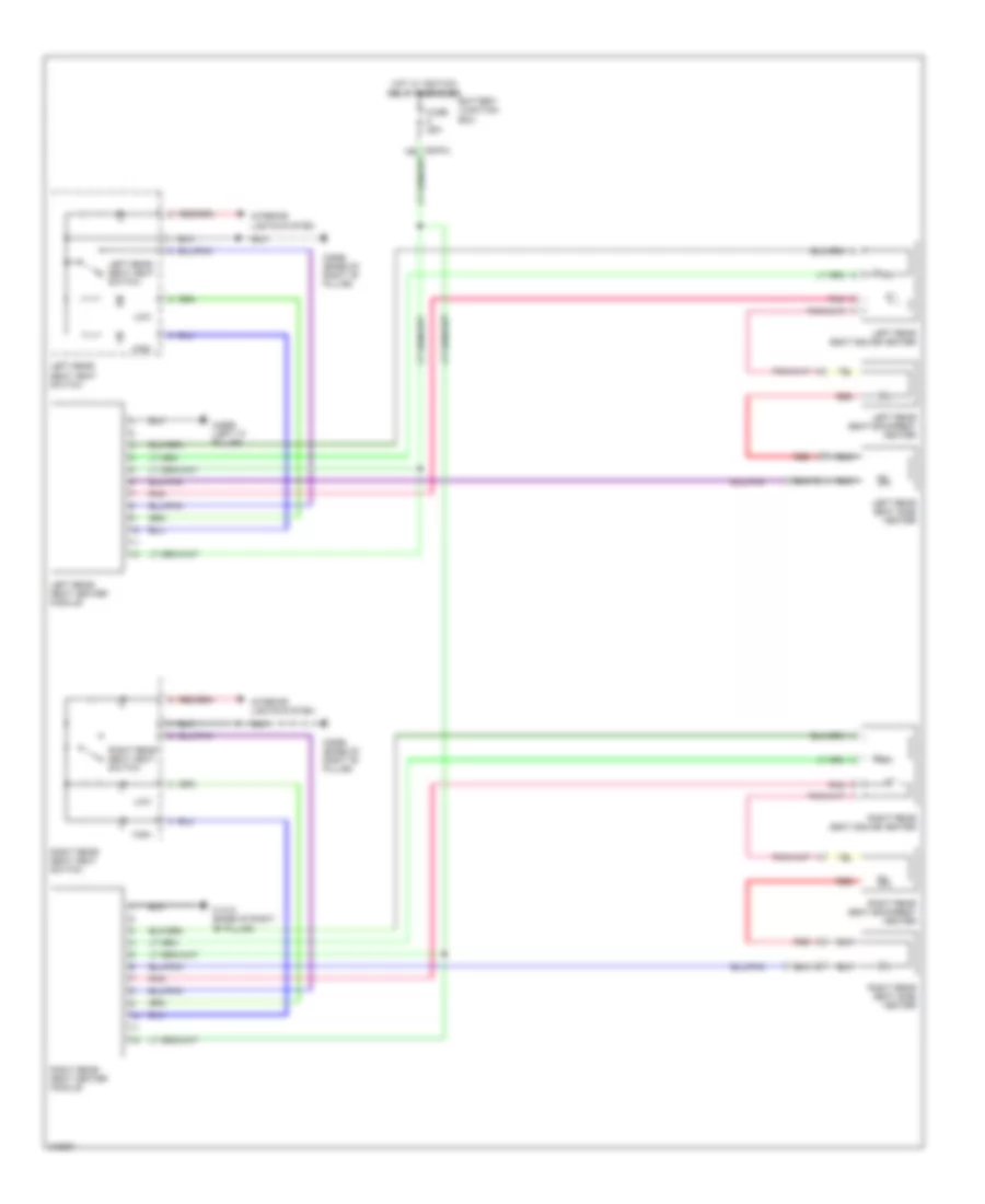
Heated Mirrors Wiring Diagram for Land Rover Discovery 3 2006
List of elements for Heated Mirrors Wiring Diagram for Land Rover Discovery 3 2006:
- Air conditioning system
- Ambient air temperature sensor (front of engine compt)
- Auto
- Automatic temperature control module
- Battery junction box
- Blower
- C0558 (right "a" pillar)
- C0580
- C0582
- C0583l
- C0635l
- C1629
- C1964
- C1970
- C2629
- C2655
- Can +
- Can -
- Can h out
- Can high +
- Can high -
- Can l out
- Can med +
- Can med -
- Central junction box
- Computer data lines system
- Defrost
- Display
- Door mirror heater
- Driver door side mirror
- Econ
- Engine control module (ecm) (left side of engine compt)
- Fr int wipe
- Fuse 10a
- Fuse 5a
- Generic electronic module
- Heated washer jets/door mirrors relay
- Hfs
- Hot at all times
- Hot in run
- Hrw
- Instrument cluster
- Intermittent
- Off
- Passenger door side mirror
- Rear
- Recirc
- Seat l
- Seat r
- Steering column wiper switch
- Temp l
- Temp r
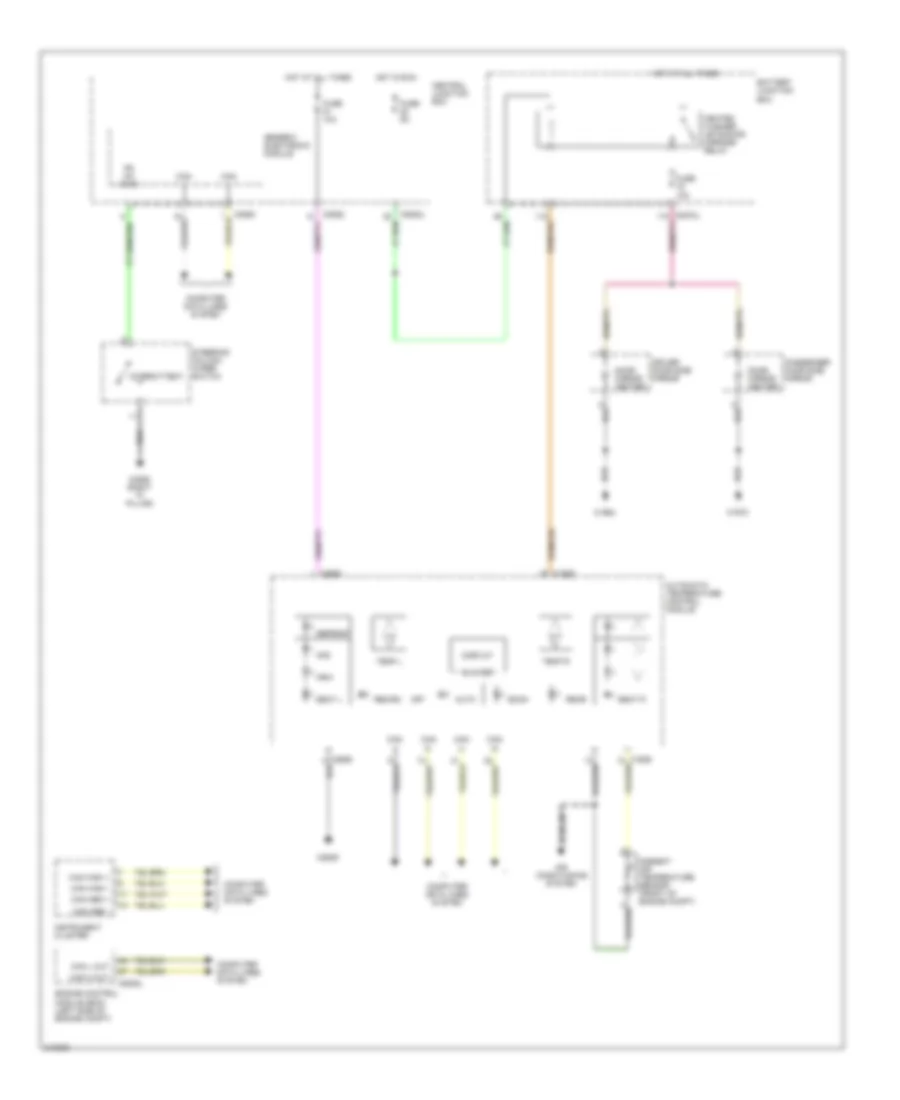
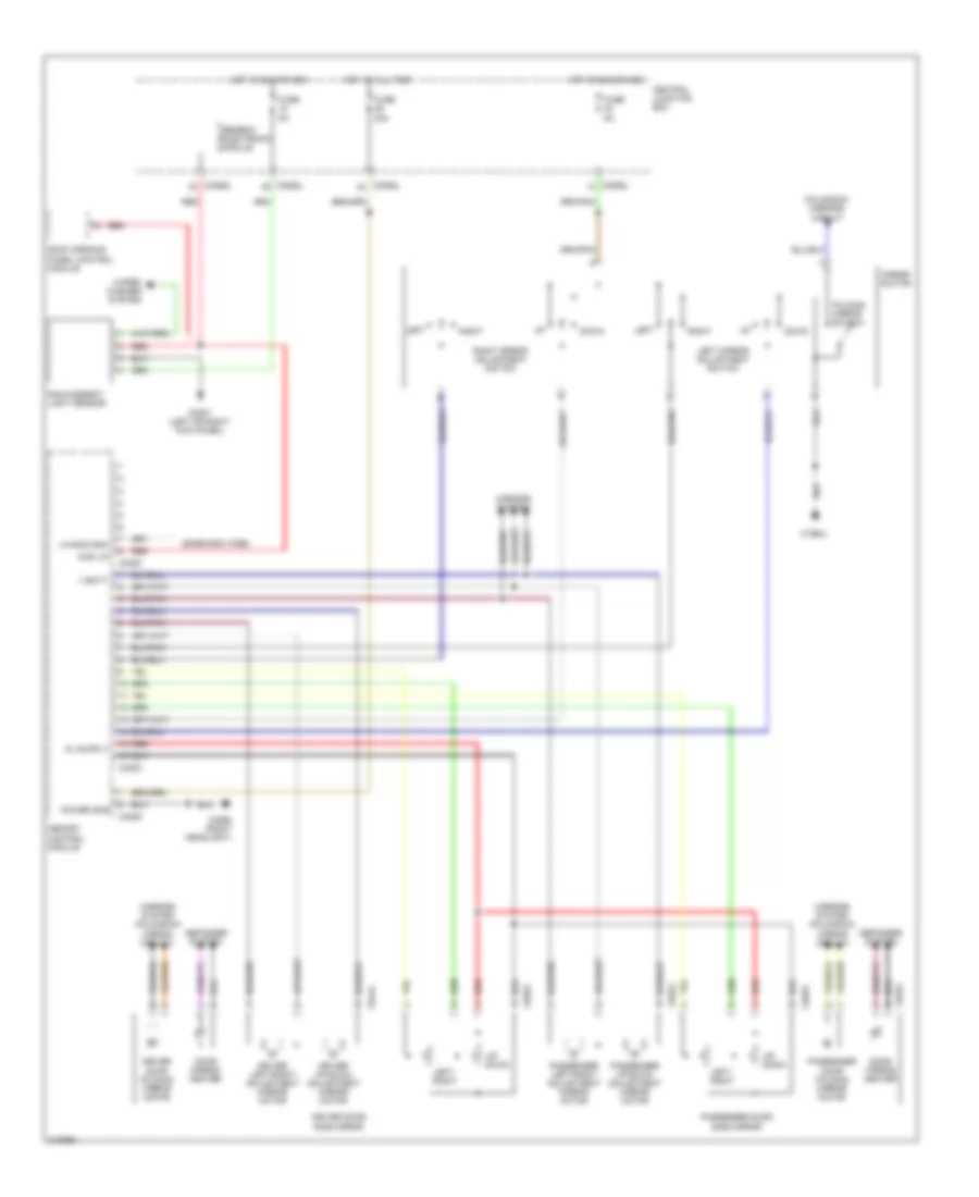
Heated Windshield Wiring Diagram for Land Rover Discovery 3 2006
List of elements for Heated Windshield Wiring Diagram for Land Rover Discovery 3 2006:
- Air conditioning system
- Ambient air temperature sensor (front of engine compt)
- Auto
- Automatic temperature control module
- Battery junction box
- Blower
- C0580
- C0582
- C0583l
- C0635l
- C1623l
- C1624
- C1629
- C2629
- C2655
- C2694
- C2713
- Can +
- Can -
- Can h out
- Can high +
- Can high -
- Can l out
- Can med +
- Can med -
- Central junction box
- Computer data lines system
- Defrost
- Display
- Econ
- Engine control module (ecm) (left side of engine compt)
- Front heated screen relay
- Fuse 10a
- Fuse 30a
- Fuse 5a
- Generic electronic module
- Hfs
- Hot at all times
- Hot in run
- Hrw
- Instrument cluster
- Left windshield heater element (left "a" pillar)
- Off
- Rear
- Recirc
- Right windshield heater element (right a" pillar)
- Seat l
- Seat r
- Temp l
- Temp r
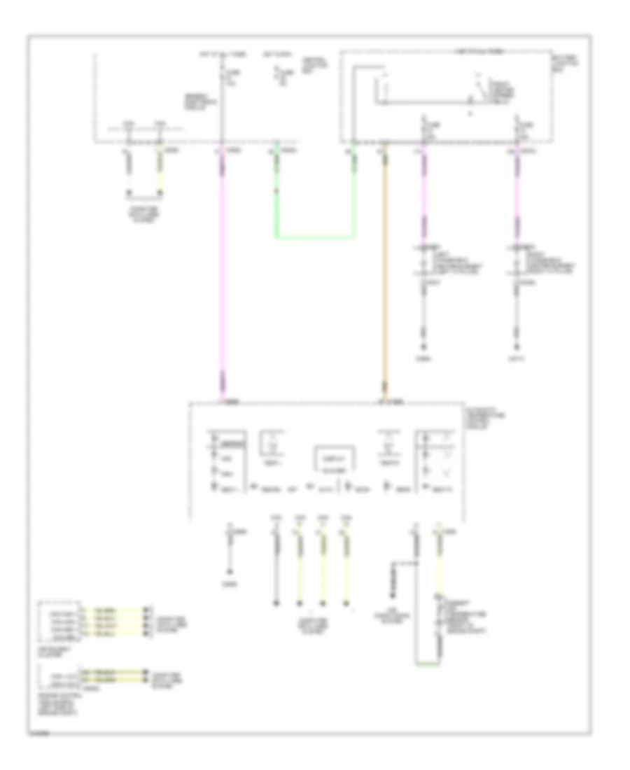
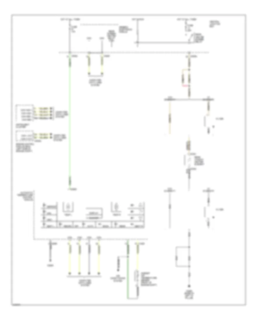
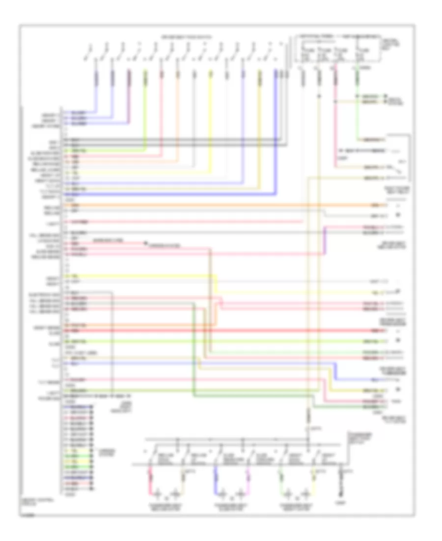
Rear Defogger Wiring Diagram for Land Rover Discovery 3 2006
List of elements for Rear Defogger Wiring Diagram for Land Rover Discovery 3 2006:
- Air conditioning system
- Ambient air temperature sensor (front of engine compt)
- Auto
- Automatic temperature control module
- Blower
- C0381
- C0580
- C0582
- C0635l
- C2568 (base of left "d" pillar)
- C2629
- C2655
- Can +
- Can -
- Can h out
- Can high +
- Can high -
- Can l out
- Can med +
- Can med -
- Central junction box
- Computer data lines system
- Defrost
- Display
- Econ
- Engine control module (ecm) (left side of engine compt)
- Filter
- Fuse 10a
- Fuse 25a
- Generic electronic module
- Hfs
- Hot at all times
- Hot in run
- Hrw
- Instrument cluster
- Nca
- Off
- Rear
- Rear heated screen relay
- Rear screen heated relay ctrl
- Rear window heater element
- Recirc
- Seat l
- Seat r
- Temp l
- Temp r
- W/ diversity
- W/o diversity
ELECTRONIC SUSPENSION
Electronic Suspension Wiring Diagram (1 of 2) for Land Rover Discovery 3 2006
List of elements for Electronic Suspension Wiring Diagram (1 of 2) for Land Rover Discovery 3 2006:
- Air suspension control module (base of left "a " pillar)
- Air suspension relay
- Battery
- Battery junction box
- C0559l (right front wheel arch liner)
- C0570l
- C2320l
- C2321l
- Comp rel pos
- Comp temp gnd
- Comp temp sig
- Comp v
- Exh v pos
- F xv pos
- Fl cv pos
- Fl height 5v
- Fl height gnd
- Fl height sig
- Fr cv pos
- Fr height 5v
- Fr height gnd
- Fr height sig
- Front control valve (behind right front wheel arch liner)
- Front cross link valve
- Fuse 26 20a
- Fuse 5a
- Fusible link 10 60a
- Ground
- Hot at all times
- Left front corner valve
- Left front height sensor (under left front side of vehicle, on chassis)
- Pnk
- Pressure 5v
- Pressure gnd
- Pressure sensor
- Pressure sig
- Red
- Res v pos
- Reservoir control valve
- Reservoir valve
- Right front corner valve
- Right front height sensor (under right front side of vehicle, on chassis)
Electronic Suspension Wiring Diagram (2 of 2) for Land Rover Discovery 3 2006
List of elements for Electronic Suspension Wiring Diagram (2 of 2) for Land Rover Discovery 3 2006:
- (under left rear side of vehicle, on chassis) left rear height sensor
- (under right rear side of vehicle, on chassis) right rear height sensor
- Access ht led
- Air sus cont
- Air suspension compressor motor
- Air suspension control module (base of left "a " pillar)
- All times
- C0561 (right headlight)
- C0586l
- C0780
- C0781
- C0867l
- C2030l
- C2598 (base of right "b" pillar)
- Can in pos
- Can out pos
- Center console switch pack
- Central junction box
- Computer data lines system
- Crawl led
- Door stat
- Exhaust valve
- Fuse 5a
- Generic electronic module
- High led
- Hot at
- Ign
- Left rear corner valve
- Lower sw
- Lowering led
- Mot temp gnd
- Mot temp sig
- Pnk
- R xv pos
- Raise sw
- Raising led
- Rear control valve (below left rear wheel arch)
- Rear cross link valve
- Red
- Right rear corner valve
- Rl cv pos
- Rl height 5v
- Rl height gnd
- Rl height sig
- Rr cv pos
- Rr height 5v
- Rr height gnd
- Rr height sig
- Std ht led
- Temperature compressor sensor
- Temperature motor sensor
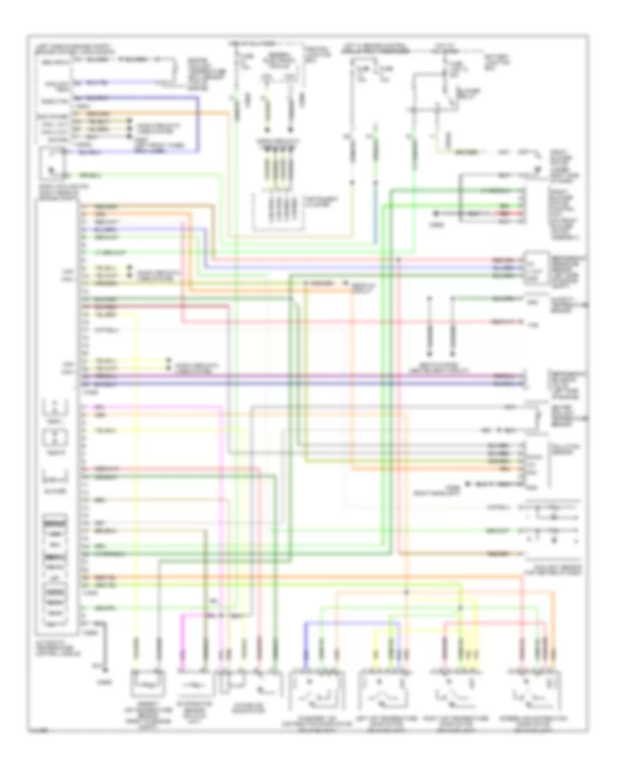
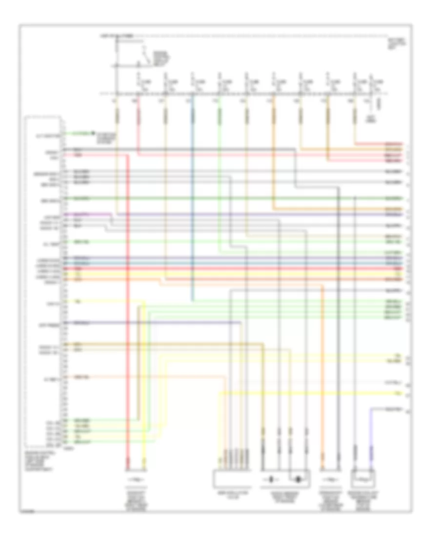
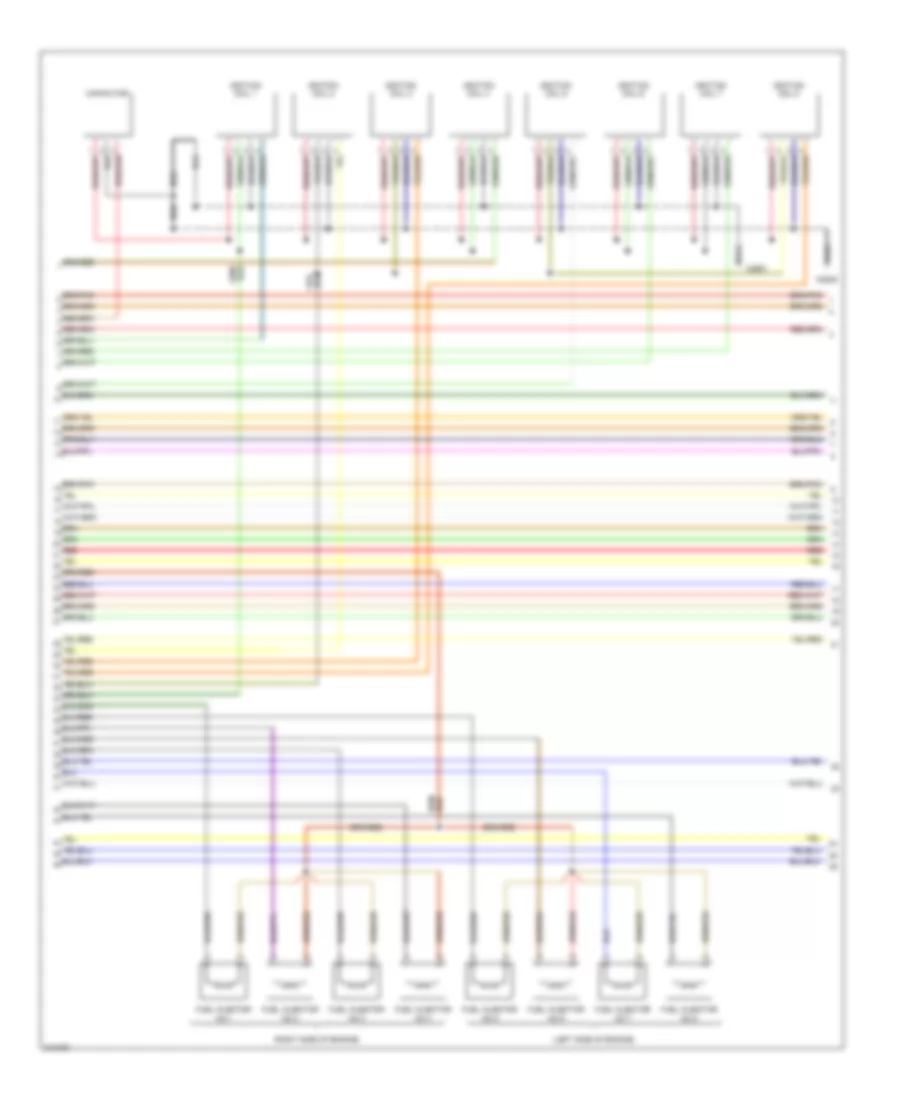
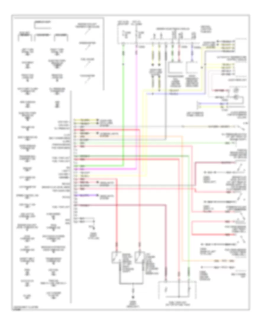
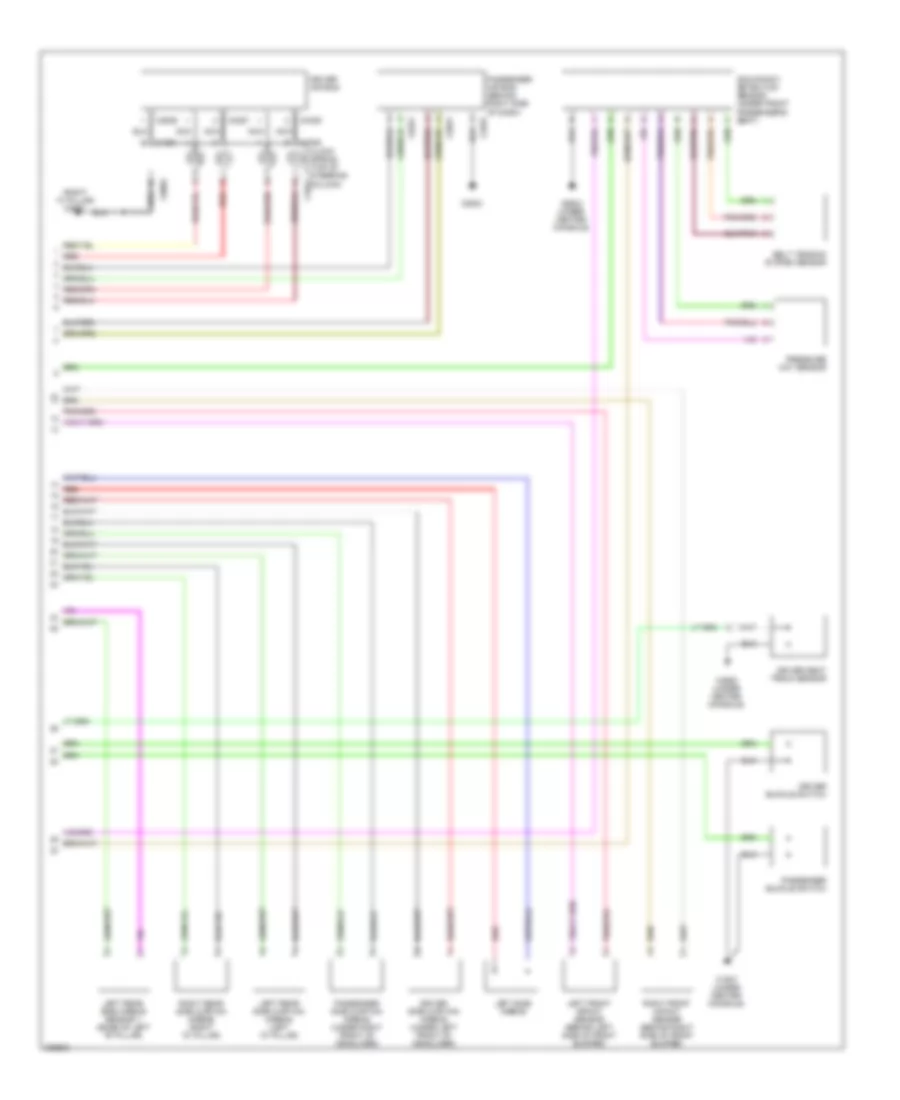
ENGINE PERFORMANCE
4.0L
4.0L, Engine Performance Wiring Diagram (1 of 4) for Land Rover Discovery 3 2006
List of elements for 4.0L, Engine Performance Wiring Diagram (1 of 4) for Land Rover Discovery 3 2006:
- (not used)
- 5v ref 4
- Alt monitor
- Battery junction box
- C0570l
- C0634
- Cam -
- Cam a+
- Camshaft position sensor a (right rear of engine)
- Coil 1b
- Coil 2a
- Coil 2b
- Coil 3a
- Coil 3b
- Crank +
- Crank -
- Crankshaft position sensor (lower rear of engine)
- Diff press
- Egr modulator valve
- Engine control module (ecm) (left side of engine compartment)
- Engine control module relay
- Engine coolant temperature sensor (top of engine)
- Fuse 10a
- Fuse 15a
- Fuse 20a
- Fuse 5a
- Gnd 4
- Hot at all times
- Knock 1a +
- Knock 1a -
- Knock 1b +
- Knock 1b -
- Knock sensor (right front of engine)
- Maf gnd
- Nca
- Oil temp
- Red
- Sen gnd 5
- Sen gnd 6
- Sensor gnd 3
- Starting/ charging system
- Uhego a gnd
- Uhego a sig
- Uhego b gnd
- Uhego b sig
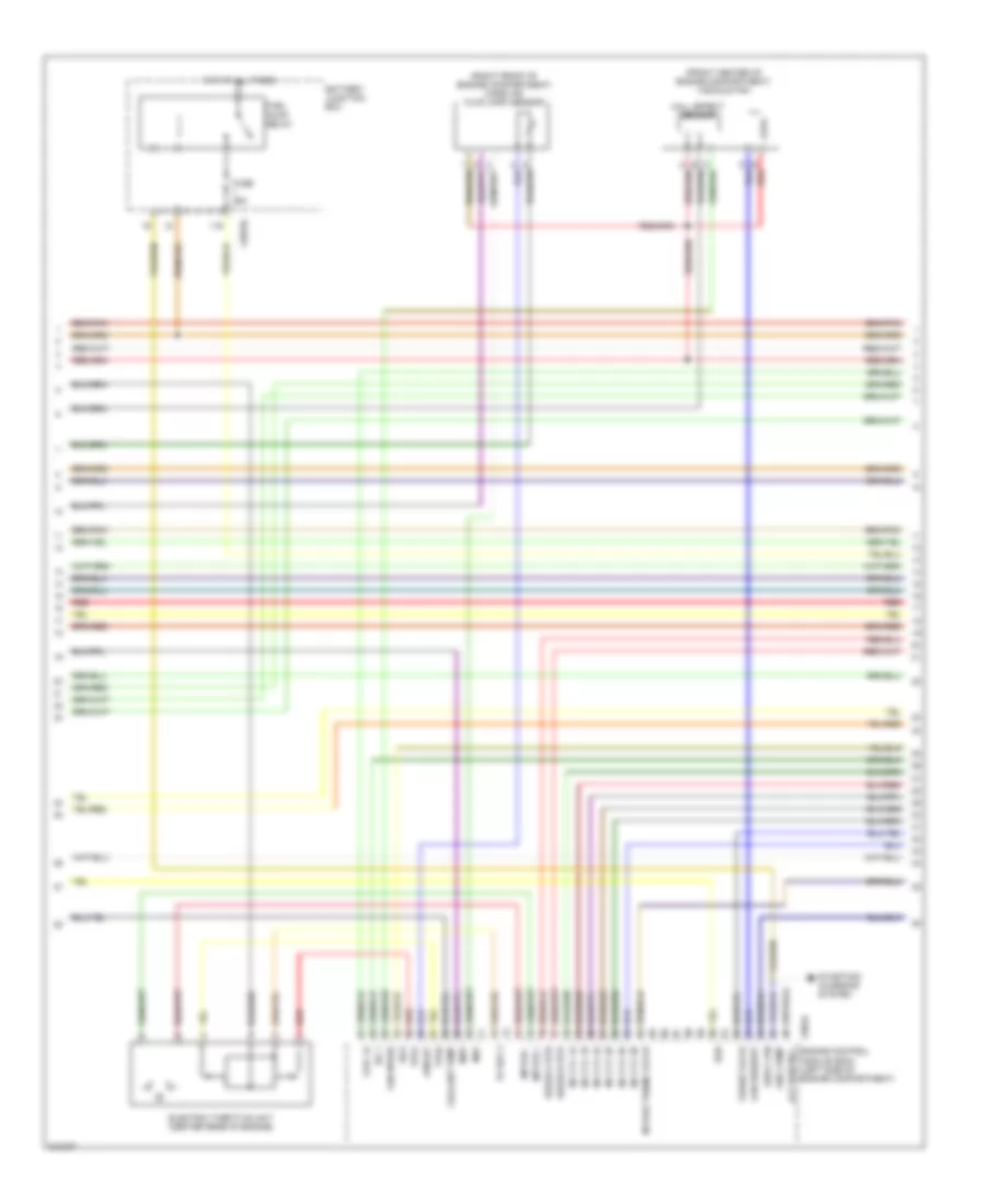
4.0L, Engine Performance Wiring Diagram (2 of 4) for Land Rover Discovery 3 2006
List of elements for 4.0L, Engine Performance Wiring Diagram (2 of 4) for Land Rover Discovery 3 2006:
- (front center of engine compartment) viscous fan
- (right front of engine compartment) mass air flow (maf) sensor
- 5v ref 3
- Afm iat
- Battery junction box
- C0570l
- C0634 alt control
- Coil 1a
- Coolant temp
- E red
- E-box fan
- Egr
- Electric throttle unit (center rear of engine)
- Engine control module (ecm) (left side of engine compartment)
- Fan request
- Fan speed
- Fuel pump
- Fuel pump relay
- Fuse 25a
- Hall effect sensor
- Hot at all times
- Igf 1
- Igf2
- Inj cyl 1a
- Inj cyl 1b
- Inj cyl 2a
- Inj cyl 2b
- Inj cyl 3a
- Inj cyl 3b
- Intake tuning valve
- Maf
- Map
- Mptor +
- Mptor -
- Purge valve
- Red
- Starting/ charging system
- Tps1
- Tps2
- Uhego a htr
- Uhego b htr
4.0L, Engine Performance Wiring Diagram (3 of 4) for Land Rover Discovery 3 2006
List of elements for 4.0L, Engine Performance Wiring Diagram (3 of 4) for Land Rover Discovery 3 2006:
- (left side of engine)
- (right side of engine)
- C2649
- C2649 (center front of engine)
- C2922 (base of left "d" pillar)
- Capacitor
- E-box cooling fan (right rear of eng compt)
- Fuel injector no 1
- Fuel injector no 2
- Fuel injector no 3
- Fuel injector no 4
- Fuel injector no 5
- Fuel injector no 6
- Fuel tank unit
- Ignition coil 1
- Ignition coil 2
- Ignition coil 3
- Ignition coil 4
- Ignition coil 5
- Ignition coil 6
- Instrument cluster system
- Manifold tuning valve (front center of engine)
- Pressure control valve
- Purge control valve
- Red
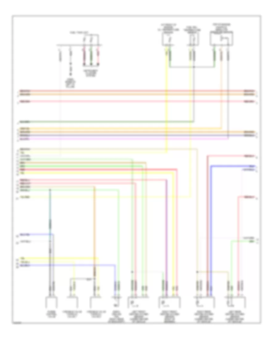
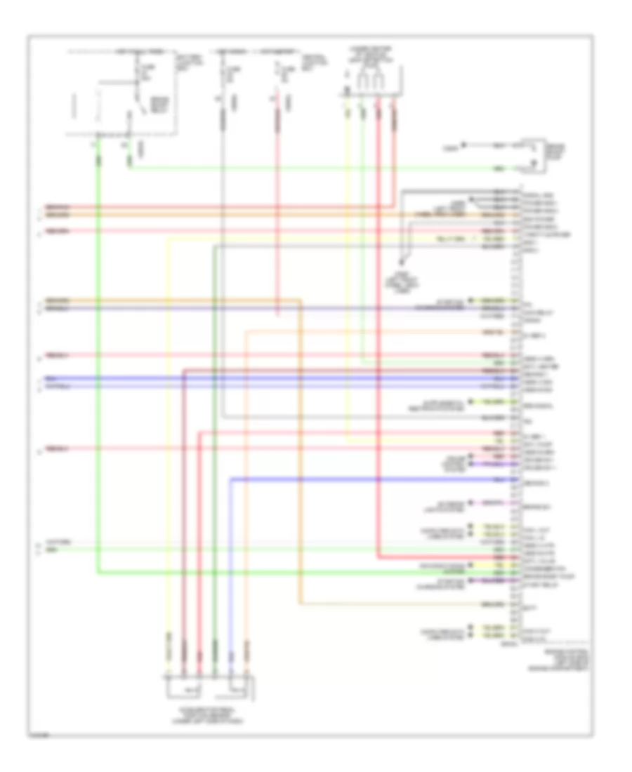
4.0L, Engine Performance Wiring Diagram (4 of 4) for Land Rover Discovery 3 2006
List of elements for 4.0L, Engine Performance Wiring Diagram (4 of 4) for Land Rover Discovery 3 2006:
- (at front of engine) oil temperature sensor
- (under center of vehicle) leak detection pump
- 5v ref 1
- 5v ref 2
- Accelerator pedal position sensor (under left side of dash)
- Batt
- Battery junction box
- Brake boost pump
- Brake boost relay
- Brake sw
- C0557 (left front wheel arch liner)
- C0570l
- C0583l
- C0584l
- C0635l
- C2635
- C2650 (left front wheel arch liner)
- Can h in
- Can h out
- Can l in
- Can l out
- Central junction box
- Computer data lines system
- Cruise control system
- Cruise sw +
- Cruise sw -
- Dmtl heater
- Dmtl pump
- Dmtl valve
- Ecm power
- Engine control module (ecm) (left side of engine compartment)
- Exterior lights system
- Fuse 20a
- Fuse 5a
- Gnd 1
- Gnd 2
- Hego a htr
- Hego a sig
- Hego b htr
- Hego b sig
- Hot at all times
- Hot in run
- Hot in start
- Ign
- Ign start
- Left front heated oxygen sensor (under center of vehicle
- Left rear heated oxygen sensor (under center of vehicle)
- Main relay
- P/n
- Pedal demand 1
- Pedal demand 2
- Power gnd 1
- Power gnd 2
- Power gnd 3
- Red
- Right front heated oxygen sensor (right of gearbox)
- Right rear heated oxygen sensor (under center of vehicle)
- Signal gnd
- Srs signal
- Start relay
- Starting/ charging system
- Throttle power
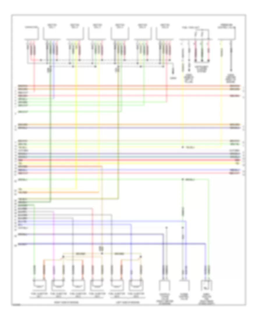
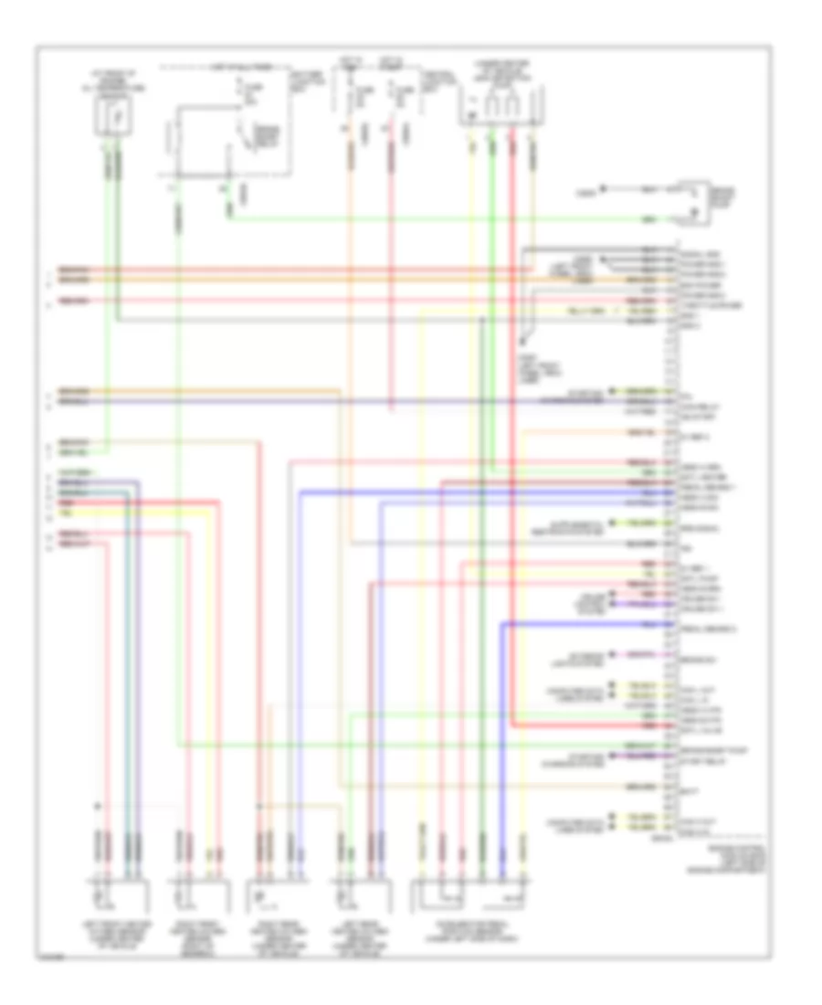
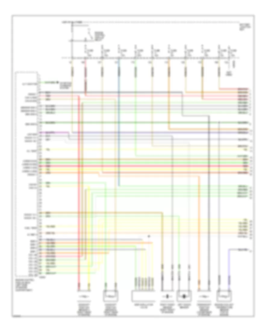
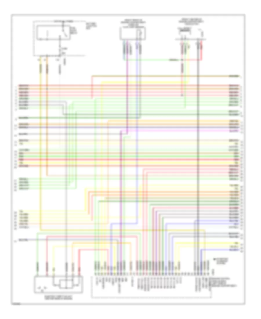
4.4L
4.4L, Engine Performance Wiring Diagram (1 of 5) for Land Rover Discovery 3 2006
List of elements for 4.4L, Engine Performance Wiring Diagram (1 of 5) for Land Rover Discovery 3 2006:
- (not used)
- 5v ref 4
- Alt monitor
- Battery junction box
- C0570l
- C0634
- Cam a gnd
- Cam a+
- Cam b gnd
- Cam b+
- Camshaft position sensor a (right rear of engine)
- Camshaft position sensor b (right rear of engine)
- Coil 1b
- Coil 2a
- Coil 2b
- Coil 3a
- Coil 3b
- Coil 4a
- Coil 4b
- Crank +
- Crank -
- Crankshaft position sensor (lower rear of engine)
- Egr 1
- Egr 2
- Egr 4
- Egr modulator valve
- Engine control module (ecm) (left side of engine compartment)
- Engine control module relay
- Engine coolant temperature sensor (top of engine)
- Fuel temp
- Fuse 10a
- Fuse 15a
- Fuse 20a
- Fuse 5a
- Hot at all times
- Knock 1a +
- Knock 1a -
- Knock 1b +
- Knock 1b -
- Left knock sensor
- Maf gnd
- Nca
- Oil temp
- Red
- Right knock sensor (right front of engine)
- Sen gnd 5
- Sen gnd 6
- Sensor gnd 3
- Sensor gnd 4
- Starting/ charging system
- Uhego a gnd
- Uhego a sig
- Uhego b gnd
- Uhego b sig
4.4L, Engine Performance Wiring Diagram (2 of 5) for Land Rover Discovery 3 2006
List of elements for 4.4L, Engine Performance Wiring Diagram (2 of 5) for Land Rover Discovery 3 2006:
- (front center of engine compartment) viscous fan
- (right front of engine compartment) mass air flow (maf) sensor
- 5v ref 3
- Afm iat
- Battery junction box
- C0570l
- C0634 alt monitor
- Coil 1a
- Coolant temp
- E red
- E-box fan
- Electric throttle unit (center rear of engine)
- Engine control module (ecm) (left side of engine compartment)
- Fan request
- Fan speed
- Fuel pump
- Fuel pump relay
- Fuse 25a
- Hall effect sensor
- Hot at all times
- Igf 1
- Igf2
- Inj cyl 1a
- Inj cyl 1b
- Inj cyl 2a
- Inj cyl 2b
- Inj cyl 3a
- Inj cyl 3b
- Inj cyl 4a
- Inj cyl 4b
- Maf
- Map
- Purge valve
- Red
- Starting/ charging system
- Throttle +
- Throttle -
- Tps1
- Tps2
- Uhego a htr
- Uhego b htr
- Vvt a
- Vvt b
4.4L, Engine Performance Wiring Diagram (3 of 5) for Land Rover Discovery 3 2006
List of elements for 4.4L, Engine Performance Wiring Diagram (3 of 5) for Land Rover Discovery 3 2006:
- (left side of engine)
- (right side of engine)
- C2649
- C2651
- Capacitor
- Fuel injector no 1
- Fuel injector no 2
- Fuel injector no 3
- Fuel injector no 4
- Fuel injector no 5
- Fuel injector no 6
- Fuel injector no 7
- Fuel injector no 8
- Ignition coil 1
- Ignition coil 2
- Ignition coil 3
- Ignition coil 4
- Ignition coil 5
- Ignition coil 6
- Ignition coil 7
- Ignition coil 8
- Red
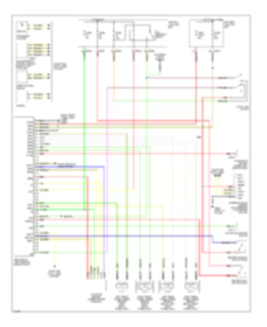
4.4L, Engine Performance Wiring Diagram (4 of 5) for Land Rover Discovery 3 2006
List of elements for 4.4L, Engine Performance Wiring Diagram (4 of 5) for Land Rover Discovery 3 2006:
- (at front of engine) oil temperature sensor
- (top of engine) manifold absolute pressure sensor
- C2922 (base of left "d" pillar)
- E-box cooling fan (right rear of eng compt)
- Fuel rail temperature sensor
- Fuel tank unit
- Instrument cluster system
- Left front heated oxygen sensor (under center of vehicle
- Left rear heated oxygen sensor (under center of vehicle)
- Purge control valve
- Red
- Right front heated oxygen sensor (right of gearbox)
- Right rear heated oxygen sensor (under center of vehicle)
- Variable valve timing oil valve 1
- Variable valve timing oil valve 2
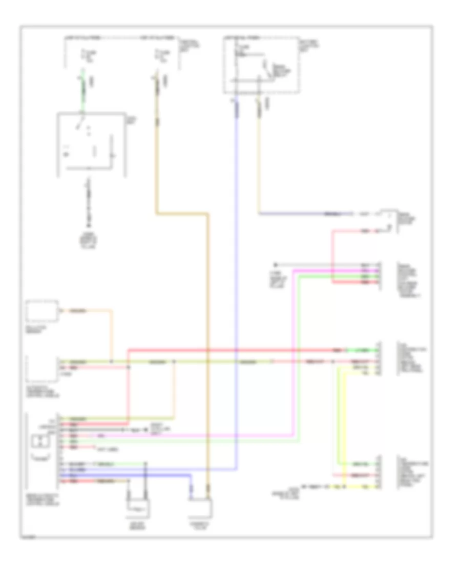
4.4L, Engine Performance Wiring Diagram (5 of 5) for Land Rover Discovery 3 2006
List of elements for 4.4L, Engine Performance Wiring Diagram (5 of 5) for Land Rover Discovery 3 2006:
- (under center of vehicle) leak detection pump
- 5v ref 1
- 5v ref 2
- Accelerator pedal position sensor (under left side of dash)
- Air conditioning system
- Batt
- Battery junction box
- Brake boost pump
- Brake boost relay
- Brake sw
- C0557 (left front wheel arch liner)
- C0570l
- C0583l
- C0584l
- C0635l
- C2635
- C2650 (left front wheel arch liner)
- Can h in
- Can h out
- Can l in
- Can l out
- Central junction box
- Computer data lines system
- Condenser fan
- Crank
- Cruise control system
- Cruise sw +
- Cruise sw -
- Demand 1
- Demand 2
- Dmtl heater
- Dmtl pump
- Dmtl valve
- Ecm power
- Engine control module (ecm) (left side of engine compartment)
- Exterior lights system
- Fuse 20a
- Fuse 5a
- Gnd 1
- Gnd 2
- Hego a htr
- Hego a sig
- Hego b htr
- Hego b sig
- Hot at all times
- Hot in run
- Hot in start
- Ign
- Main relay
- P/n
- Power gnd 1
- Power gnd 2
- Power gnd 3
- Red
- Signal gnd
- Srs signal
- Start relay
- Starting/ charging system
- Throttle power
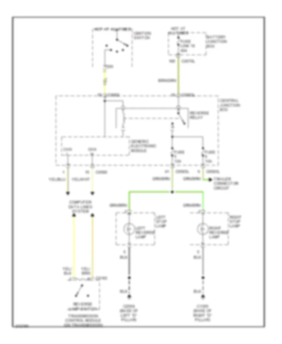
EXTERIOR LIGHTS
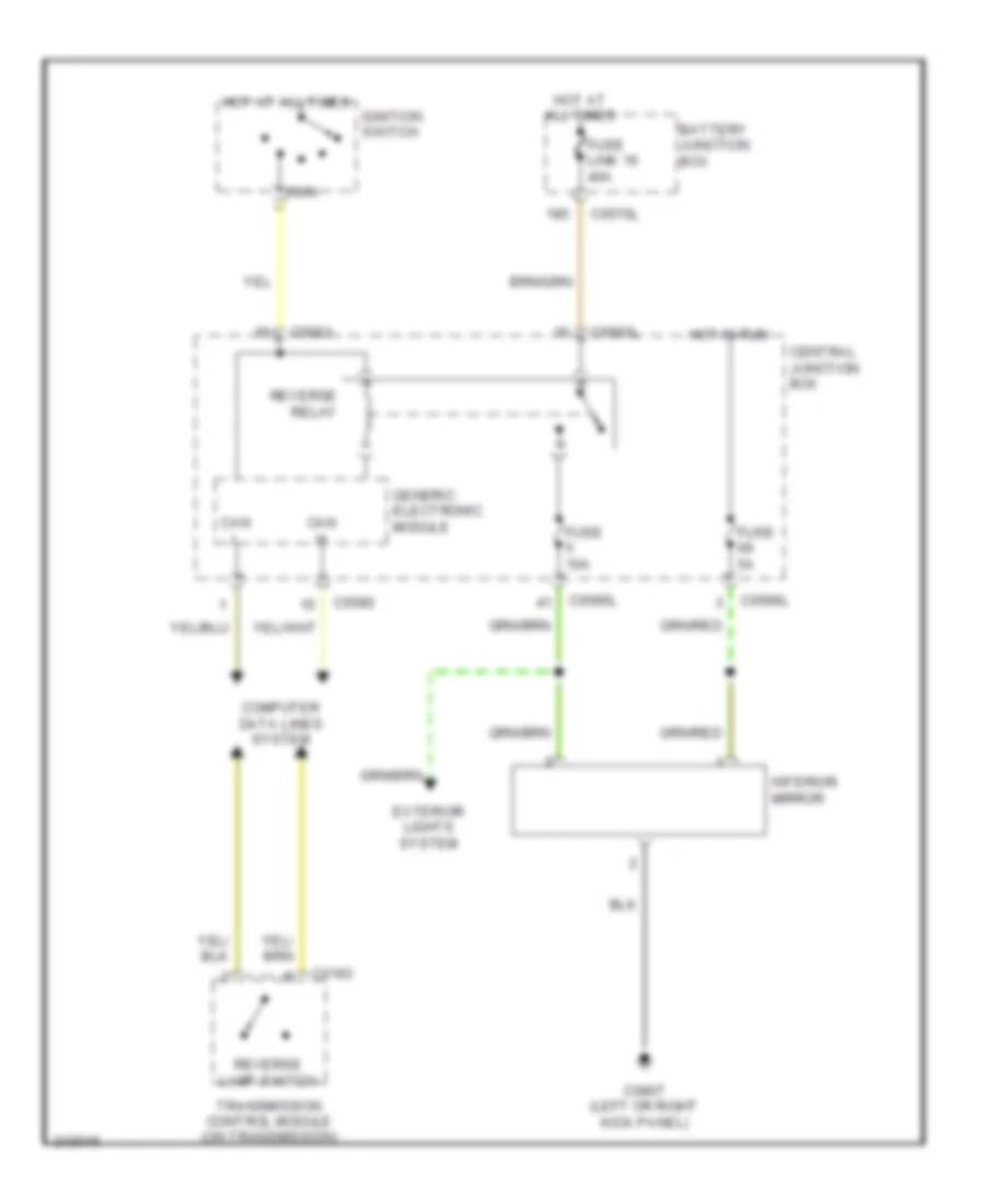
Backup Lamps Wiring Diagram for Land Rover Discovery 3 2006
List of elements for Backup Lamps Wiring Diagram for Land Rover Discovery 3 2006:
- Battery junction box
- C0193
- C0570l
- C0580
- C0582
- C0583l
- C0585l
- C1355 (base of right "d" pillar)
- C2568 (base of left "d" pillar)
- Can h
- Can l
- Central junction box
- Computer data lines system
- Fuse 10a
- Fuse link 16 40a
- Generic electronic module
- Hot at all times
- Ign
- Ignition switch
- Left reverse lamp
- Left stop lamp
- Reverse lamp switch
- Reverse relay
- Right reverse lamp
- Right stop lamp
- Trailer connector circuit
- Transmission control module (on transmission)
Exterior Lamps & Trailer connector Wiring Diagram (1 of 2) for Land Rover Discovery 3 2006
List of elements for Exterior Lamps & Trailer connector Wiring Diagram (1 of 2) for Land Rover Discovery 3 2006:
- 40a
- Auto
- Auto lights relay
- Batt
- Battery junction box
- C0561 right headlight)
- C0564 (left front of engine compt)
- C0570l
- C0580
- C0582
- C0583l
- C0807
- C2627 (right "a" pillar)
- Can +
- Can -
- Central junction box
- Computer data lines system
- Dip
- Dip/ main beam
- Direction indicator switch
- Flash
- Fuse 10a
- Fuse 5a
- Fuse link 15
- Fuse link 16
- Generic electronic module
- Hot at all times
- Hot in run
- Hot in run & acc
- Instrument cluster
- Left corner lamp
- Left corner lamp fet
- Left front side marker lamp
- Left headlamp
- Left ind
- Left side lamp
- Left turn sign ind
- Lighting control switch
- Line bus
- Main
- Power tops & memory systems
- Rain light sensor (on top center of windshield, behind rear view mirror)
- Red
- Right corner lamp
- Right corner lamp fet
- Right front side marker lamp
- Right headlamp
- Right ind
- Right side lamp
- Right turn sign ind
- Side lamp relay
- Steering angle sensor (on underside of steering column)
- Steering column lighting switch
- To left indicator fet (diagram 2 of 2)
- Turn signal indicator/ hazard flasher lamp
- Wiper/ washer system
Exterior Lamps & Trailer connector Wiring Diagram (2 of 2) for Land Rover Discovery 3 2006
List of elements for Exterior Lamps & Trailer connector Wiring Diagram (2 of 2) for Land Rover Discovery 3 2006:
- (base of left "d" pillar) c2568
- Abs module (left rear of engine compt)
- Anti-lock brakes system
- Backup lamps circuit
- Battery junction box
- C0506l
- C0565
- C0570l
- C0580
- C0583l
- C0585l
- C0586l
- C1319l
- C1355 (base of right "d" pillar)
- C1413
- C1964
- C1970
- C2568 (base of left "d" pillar)
- C2629
- Center facia pack switch
- Central junction box
- Computer data lines system
- Earth
- From a fuse link 16 (diagram 1 of 2)
- Fuse 10a
- Fuse 15a
- Fuse 30a
- Fuse link 6 30a
- Generic electronic module
- Gnd
- Hazard warning switch
- Headlights system
- High mounted stop lamp
- Hill descent relay
- Hot at all times
- Hot at all times
- Hot in run
- Ign
- Left front side repeater lamp
- Left ind fet
- Left rear guard fog lamp
- Left rear side marker lamp
- Left reverse lamp
- Left stop lamp
- Left tail lamps
- Left trailer ind fet
- Lh ind/stop
- Nca
- Number plate & tail door switch lamp
- Plate lamp license
- Red
- Rev
- Reverse lamp relay
- Rh ind/stop
- Right front side repeater lamp
- Right ind fet
- Right rear guard fog lamp
- Right rear side marker lamp
- Right reverse lamp
- Right stop lamp
- Right tail lamps
- Stop lamp switch
- Tail
- Trailer electric brake module
- Trailer pickup
- Trailer pickup (4 pin)
- Trailer relay
- Trailer/ rear wiper relay
- Transfer control box module (at rear of engine compt)
- Turn signal indicator/ hazard flasher lamp
GROUND DISTRIBUTION
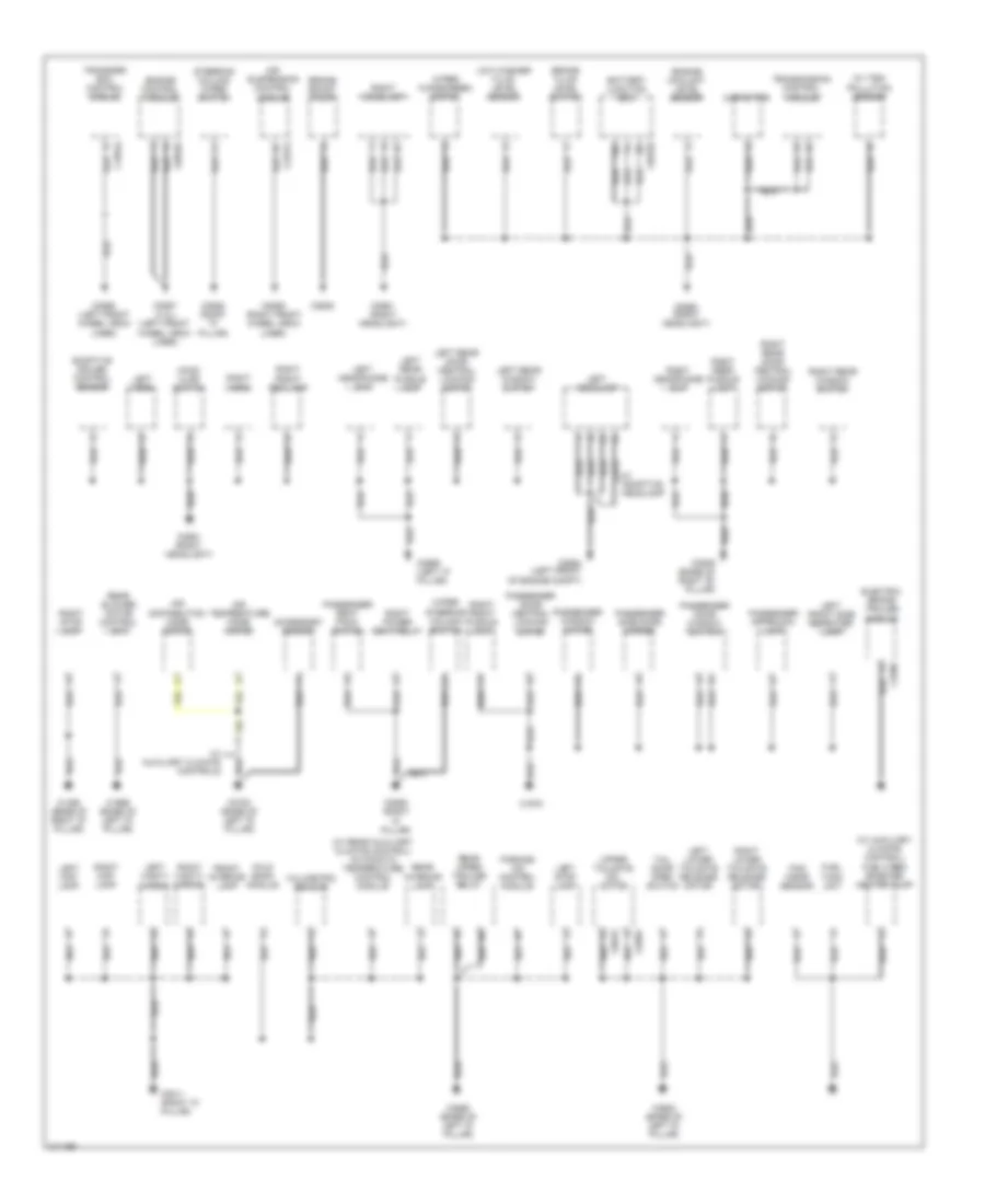
Ground Distribution Wiring Diagram (1 of 3) for Land Rover Discovery 3 2006
List of elements for Ground Distribution Wiring Diagram (1 of 3) for Land Rover Discovery 3 2006:
- (w/ auxiliary climate control) fuel fired booster heater pump
- (w/ rear auxiliary climate control) automatic temperature control module
- (w/ tsd) pollution sensor
- Accessory socket
- Adaptive cruise control sensor
- Air distribution mode motor
- Air suspension control module
- Air temperature mode motor
- Battery junction box
- Brake boost pump
- Brake fluid level switch
- C0383
- C0556 (left front wheel arch liner)
- C0557 (4.4l) (left front wheel arch liner)
- C0558 (right "a" pillar)
- C0559 (right front wheel arch liner)
- C0560 (right headlight)
- C0561 (right headlight)
- C0564 (left front of engine compt)
- C0570l
- C0616
- C0635l
- C0809 (base of right "b" pillar)
- C0811 (right "a" pillar)
- C1355 (base of right "d" pillar)
- C1854l
- C1969 (base of left "d" pillar)
- C1970
- C2321l
- C2565 (left "c" pillar)
- C2568 (base of left "d" pillar)
- C2590
- C2635
- C2700 (base of left "d" pillar)
- C2922 (base of left "d" pillar)
- Capacitor
- Electric brake trailer module
- Engine control module
- Engine coolant level sensor
- Fold back module
- Front interior lamp
- Fuel tank unit
- Hood ajar switch
- Left front side repeater lamp
- Left headlamp
- Left headphone unit
- Left horn
- Left lower tailgate release motor
- Left map lamp
- Left rear door central locking motor
- Left rear puddle lamp
- Left rear window switch
- Left stop lamp
- Left vanity mirror
- Low washer fluid level sensor
- Pad wear sensor
- Parking aid control module
- Passenger approach lamp
- Passenger door central locking motor
- Passenger door window switch
- Passenger seat pack switch
- Passenger side door mirror
- Passenger window motor
- Rear blower motor control unit
- Rear interior lamp
- Rear wiper trailer relay
- Right front fog lamp
- Right front puddle lamp
- Right headlamp
- Right headphone unit
- Right horn
- Right lower tailgate release motor
- Right map lamp
- Right power seat relay
- Right rear door central locking motor
- Right rear puddle lamp
- Right rear window switch
- Right stop lamp
- Right vanity mirror
- Steering column wiper switch
- Tail door open switch
- Transfer box control module
- Transmission control module
- Upper tailgate cdl motor
- Volumetric sensor
- W/ adaptive headlamp
- W/ auxiliary climate controls
- Wiper steering column switch
- Wiper windscreen motor
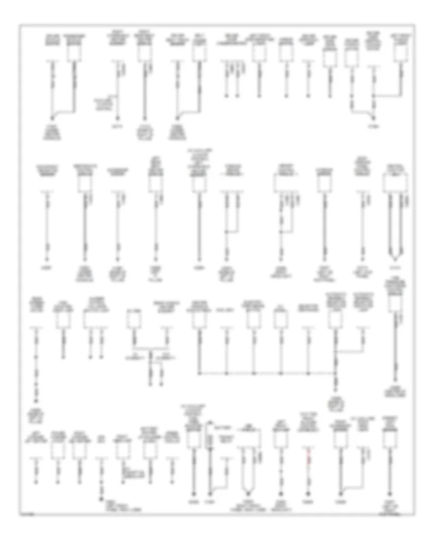
Ground Distribution Wiring Diagram (2 of 3) for Land Rover Discovery 3 2006
List of elements for Ground Distribution Wiring Diagram (2 of 3) for Land Rover Discovery 3 2006:
- (w/ auxiliary climate control)
- (w/ auxiliary climate control) fuel fired booster heater
- (w/ low line) audio head unit
- (w/o tsd) front blower control motor unit
- Abs module
- Accessory socket
- Adaptive headlamp
- Afs ecu
- Ambient light rain sensor
- Automatic gearbox selector indicator lamp
- Avi panel
- Battery
- Battery backed up sounder alarm
- Belt
- C0081
- C0246l
- C0343
- C0506l
- C0560 (right headlight)
- C0561 (right headlight)
- C0585l
- C0784
- C0807 (left or right kick panel)
- C1412 (base of right "b" pillar)
- C1413
- C1537
- C1661
- C1692
- C1947 (under center console)
- C1964
- C1967 (base of right "b" pillar)
- C2084
- C2115
- C2382
- C2385
- C2561 (under center console)
- C2562 (under center console)
- C2566 (left "c" pillar)
- C2568 (base of left "d" pillar)
- C2569 (center of headliner)
- C2570 (base of left "d" pillar)
- C2597
- C2598 (base of right "b" pillar)
- C2601 (left front wheel arch liner)
- C2603 (right front wheel arch liner)
- C2606
- C2626
- C2652
- C2694
- C2712 (left kick panel)
- C2713
- C3224
- Center console switch pack
- Central junction box
- Cool box
- Driver approach lamp
- Driver buckle switch
- Driver door central locking motor
- Driver door window switch
- Driver seat track sensor
- Driver side door mirror
- Driver window motor
- Electric park brake switch
- Filter
- Front accessory socket
- High mounted stop lamp
- Interior mirror
- Left front fog lamp
- Left front puddle lamp
- Left front side repeater lamp
- Left rear seat heater module
- Left washer jet heater
- Left windshield heater element
- Memory control module
- Minder mat
- Mirror switch
- Number plate & tail door switch lamp
- Occupancy detector sensor
- Parking brake module
- Passenger buckle switch
- Power washer pump
- Rear screen wiper motor
- Rear window heater element
- Red
- Restraints control module
- Right headlamp
- Right rear seat heater module
- Right washer jet heater
- Right windshield heater element
- Roof opening panel control module
- Selector mechanism
- Speed control module
- Tire pressure monitoring control module
- Transit relay
- W/ auxiliary climate control
- W/ diversity
- W/o diversity
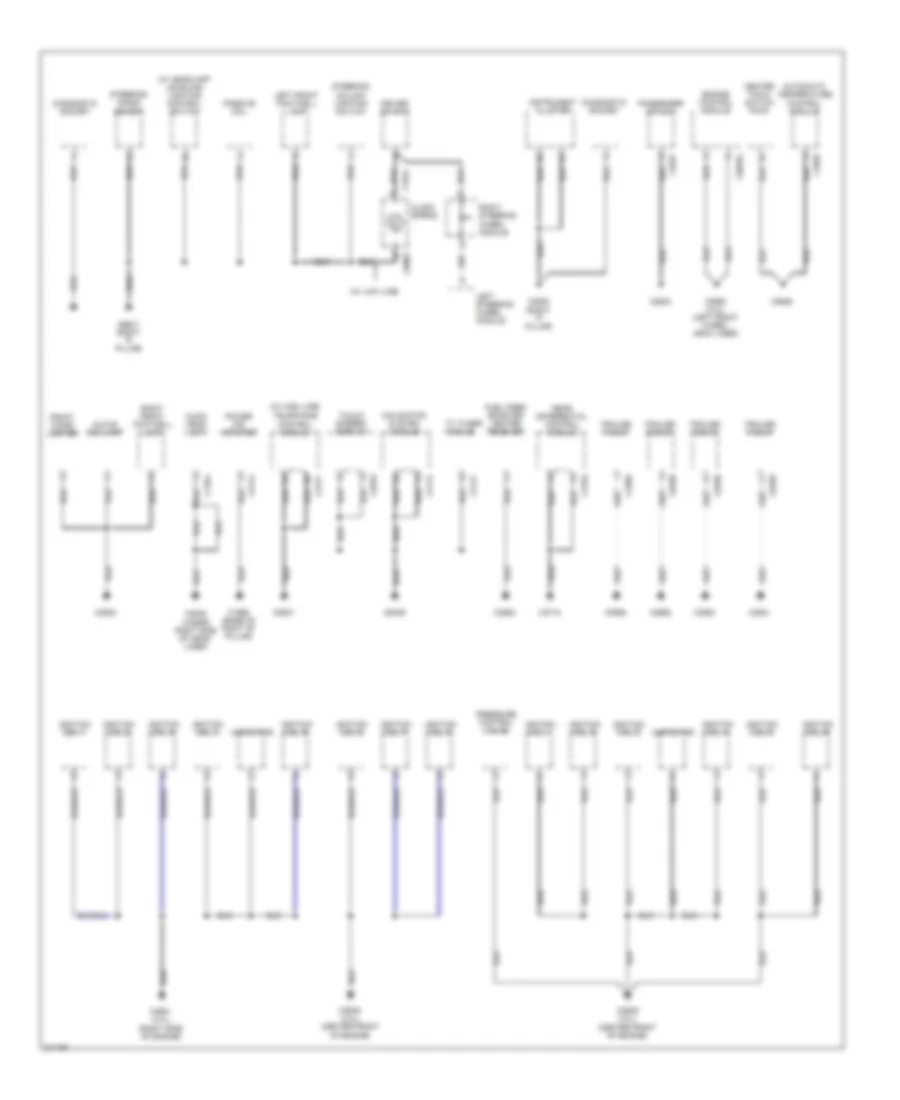
Ground Distribution Wiring Diagram (3 of 3) for Land Rover Discovery 3 2006
List of elements for Ground Distribution Wiring Diagram (3 of 3) for Land Rover Discovery 3 2006:
- (w/ headlamp leveling) lighting control switch
- (w/ high line)
- (w/ low line)
- Audio head unit
- Automatic temperature control module
- C0082
- C0499
- C0565
- C0635l
- C1254
- C1354
- C1968 (base of right "b" pillar)
- C2114
- C2117
- C2163
- C2414
- C2586
- C2627 (right "a" pillar)
- C2628 (right "a" pillar)
- C2629
- C2630
- C2633
- C2637
- C2645 (under right side of head- liner)
- C2646
- C2647
- C2649 (4.0l) (center front of engine)
- C2649 (4.4l) (center front of engine)
- C2650 (4.4l) (left front wheel arch liner)
- C2651 (4.4l) (right side of engine)
- C2652
- C2655
- C2692
- C2715
- C2777
- C2819
- C2920
- C2921
- Capacitor
- Center facia switch pack
- Clock spring
- Diagnostic socket
- Driver air bag
- Engine control module
- Front cigar lighter
- Fuel fired booster heater receiver
- Glove box lamp
- Ignition coil 1
- Ignition coil 2
- Ignition coil 3
- Ignition coil 4
- Ignition coil 5
- Ignition coil 6
- Ignition coil 7
- Ignition coil 8
- Instrument cluster
- Left front footwell lamp
- Left steering wheel module
- Navigation system module
- Passenger air bag
- Passive coil
- Power ice amplifier
- Pressure control valve
- Rear differential control module
- Right front footwell lamp
- Right steering wheel module
- Steering angle sensor
- Steering column lighting switch
- Telephone control module
- Touch screen display
- Trailer pickup
- Tv tuner module
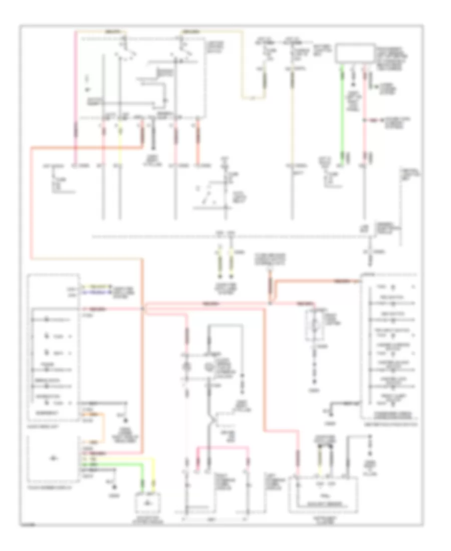
HEADLIGHTS
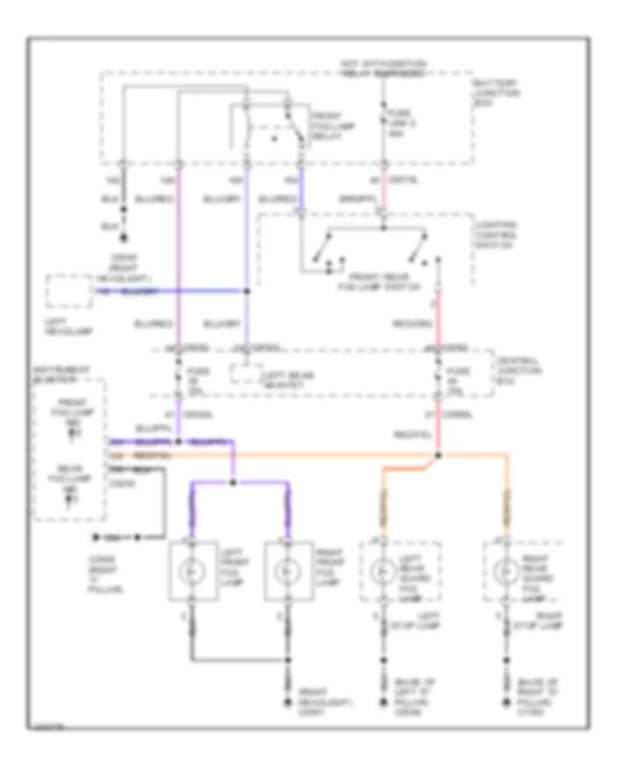
Fog Lamp Wiring Diagram for Land Rover Discovery 3 2006
List of elements for Fog Lamp Wiring Diagram for Land Rover Discovery 3 2006:
- (base of left "d" pillar) c2568
- (base of right "d" pillar) c1355
- (right headlight) c0561
- Battery junction box
- C0230
- C0560 (right headlight)
- C0570l
- C0582
- C0583l
- C0585l
- C2628 (right "a" pillar)
- Central junction box
- Front fog lamp ind
- Front fog lamp relay
- Front/ rear fog lamp switch
- Fuse 15a
- Fuse link 2 40a
- Hot with ignition relay energized
- Instrument cluster
- Left beam main fet
- Left front fog lamp
- Left headlamp
- Left rear guard fog lamp
- Left stop lamp
- Lighting control switch
- Rear fog lamp ind
- Right front fog lamp
- Right rear guard fog lamp
- Right stop lamp
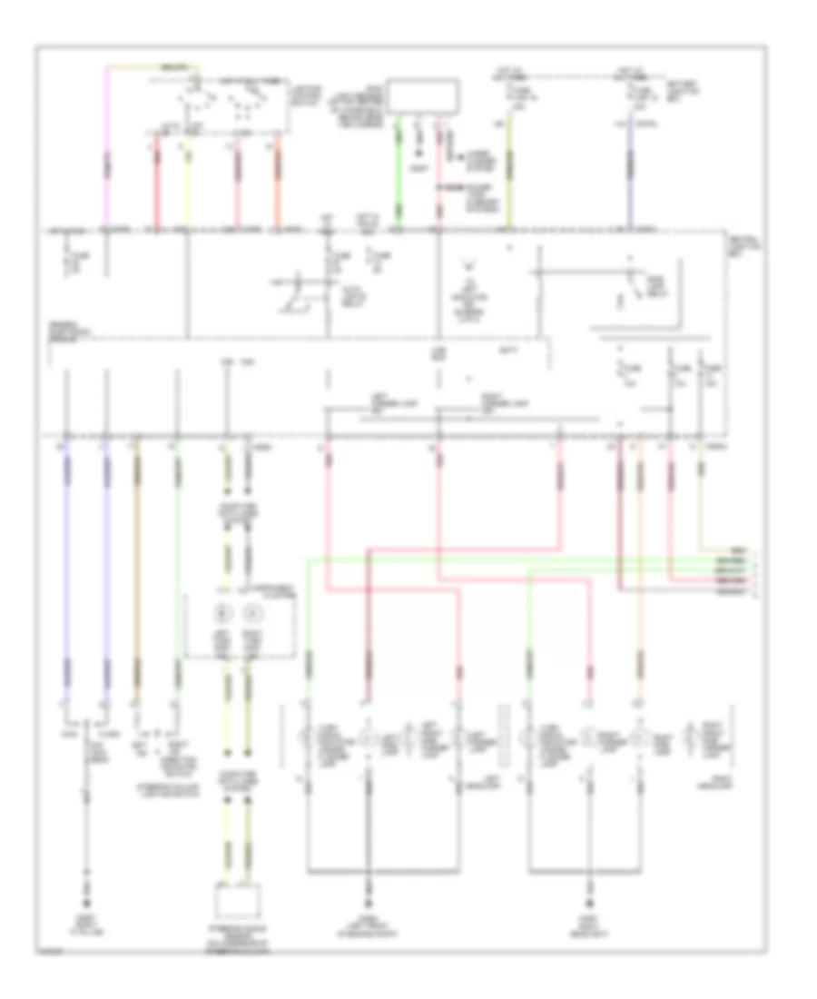
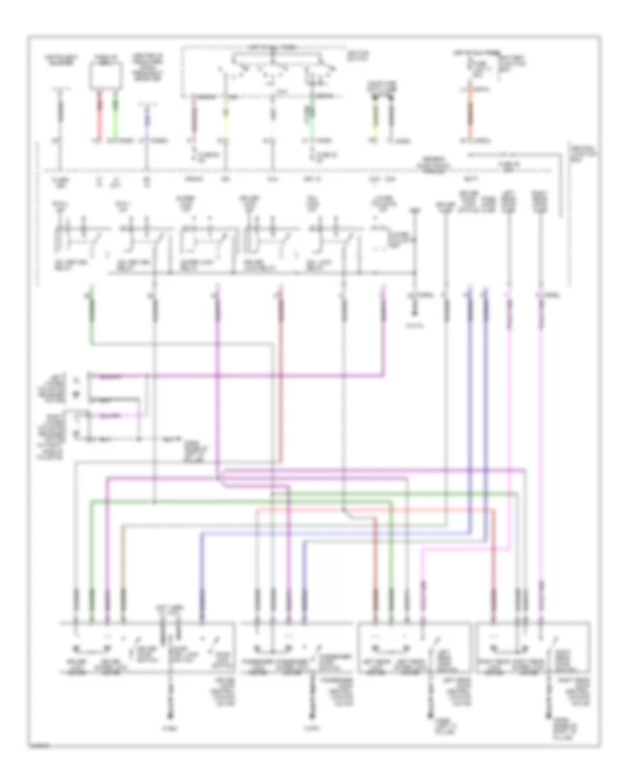
Headlamps Wiring Diagram, with Adaptive Lamp Monitor (1 of 2) for Land Rover Discovery 3 2006
List of elements for Headlamps Wiring Diagram, with Adaptive Lamp Monitor (1 of 2) for Land Rover Discovery 3 2006:
- -throttle pedal position -engine speed -engine acceleration -engine torque -brake pedal status
- Abs module (left rear of engine compt)
- Air suspension control module (base of left "a" pillar)
- Auto
- Auto lights relay
- C0580
- C0582
- C0585l
- C0586l
- C0807
- C0867l
- C1319l
- C2627 (right "a" pillar)
- Can +
- Can -
- Central junction box
- Computer data lines system
- Dip
- Dip/ main beam
- Engine control module (ecm) (left side of engine compt)
- Flash
- Fuse 5a
- Generic electronic module
- Hot at all times
- Hot in run
- Hot in run & acc
- Instrument cluster
- Lighting control switch
- Line bus
- Main
- Main beam ind
- Parking brake module
- Power top & memory systems
- Rain/ambient light sensor (on top center of windshield, behind rear view mirror)
- Rear differential control module (under center console)
- Red
- Restraints control module (under center console)
- Steering angle sensor (on underside of steering column)
- Steering column lighting switch
- Transfer box control module (at rear of engine compt)
- W/ locking rear diff
- W/o locking rear diff
- Wiper/ washer system
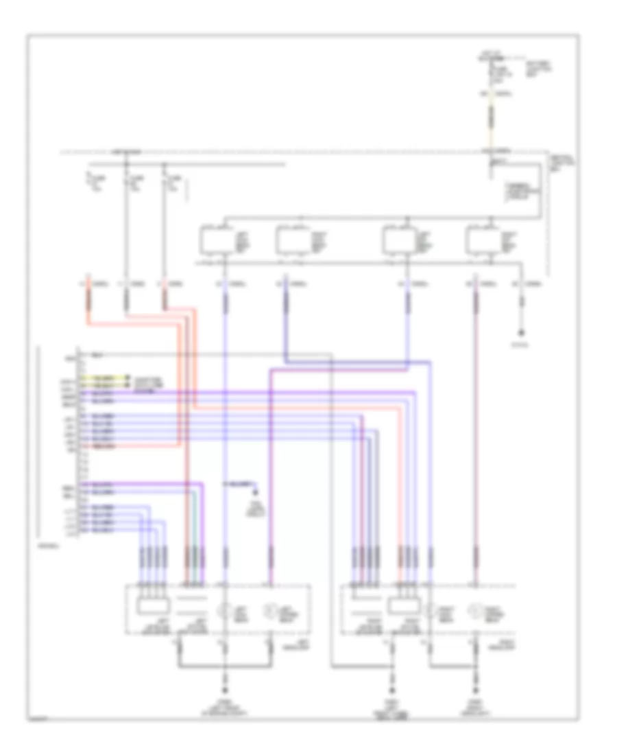
Headlamps Wiring Diagram, with Adaptive Lamp Monitor (2 of 2) for Land Rover Discovery 3 2006
List of elements for Headlamps Wiring Diagram, with Adaptive Lamp Monitor (2 of 2) for Land Rover Discovery 3 2006:
- Afs ecu
- Batt
- Battery junction box
- C0561 (right headlight)
- C0564 (left front of engine compt)
- C0570l
- C0582
- C0583l
- C0585l
- C1413l
- C2601 (left front wheel arch liner)
- Can h
- Can l
- Central junction box
- Computer data lines system
- Fog lamps circuit
- Fuse 10a
- Fuse link 16 40a
- Generic electronic module
- Gnd
- Hot at all times
- Hot in run
- Ign
- Left dip beam fet
- Left dipped beam
- Left headlamp
- Left leveling actuator
- Left main beam
- Left main beam fet
- Left swivel actuator
- Ll1+
- Ll1-
- Ll2+
- Ll2-
- Lr1+
- Lr1-
- Lr2+
- Lr2-
- Right dip beam fet
- Right dipped beam
- Right headlamp
- Right leveling actuator
- Right main beam
- Right main beam fet
- Right swivel actuator
- Sbgl
- Sbgr
- Sbll
- Sblr
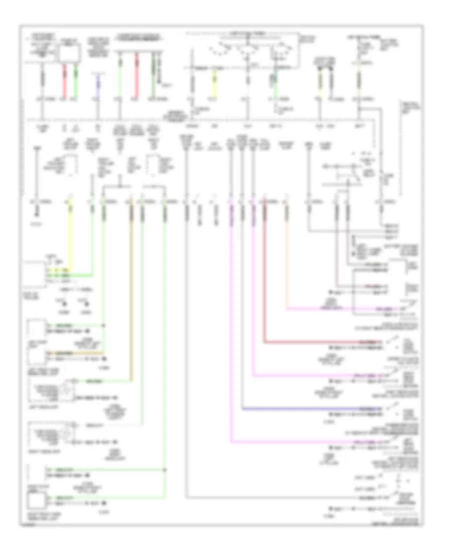
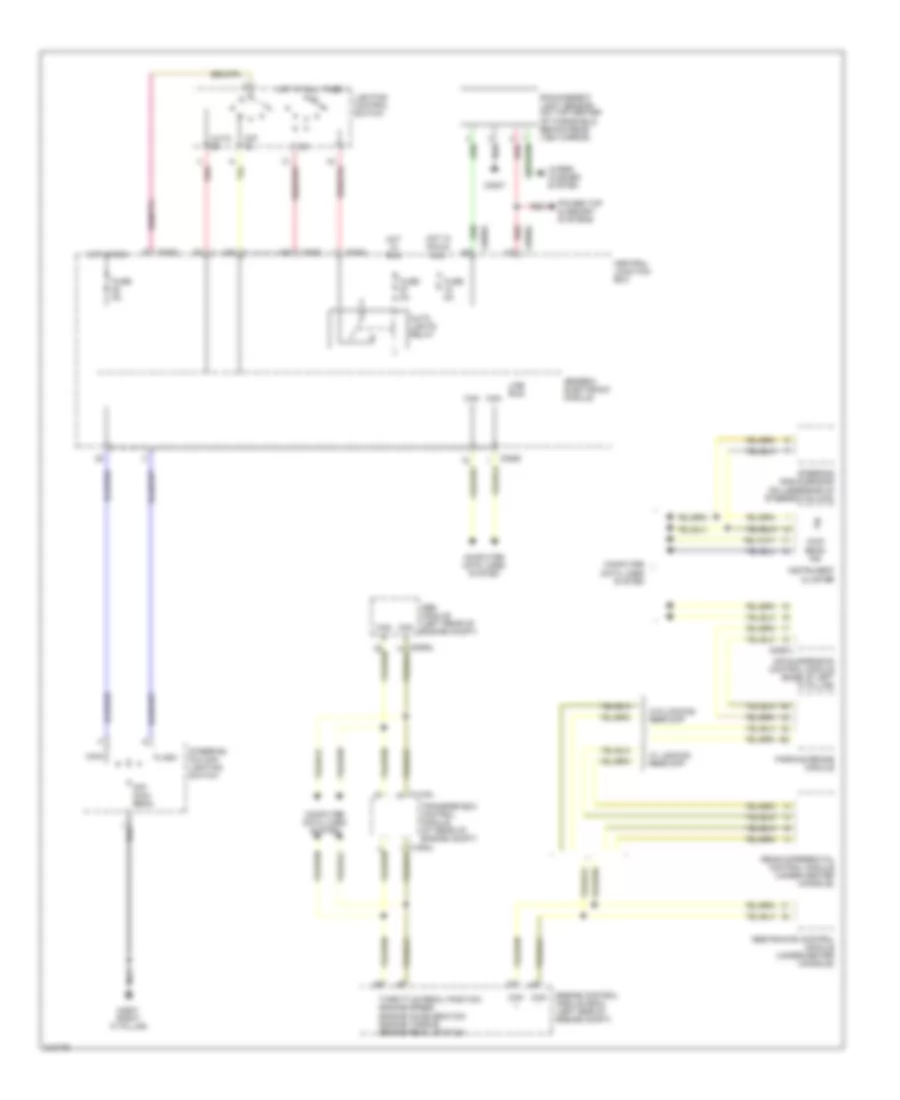
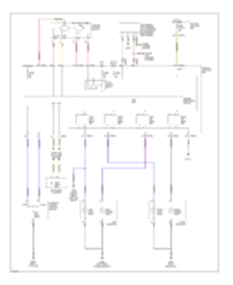
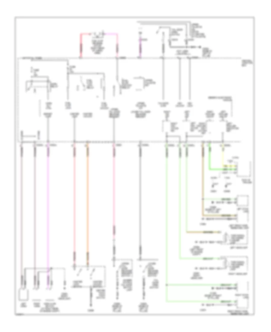
Headlamps Wiring Diagram, without Adaptive Lamp Monitor for Land Rover Discovery 3 2006
List of elements for Headlamps Wiring Diagram, without Adaptive Lamp Monitor for Land Rover Discovery 3 2006:
- 40a
- Auto
- Auto lights relay
- Batt
- Battery junction box
- C0561 (right headlight)
- C0564 (left front of engine compt)
- C0570l
- C0580
- C0582
- C0583l
- C0585l
- C0586l
- C0807
- C1413l
- C2627 (right "a" pillar)
- Can +
- Can -
- Central junction box
- Computer data lines system
- Dip
- Dip/ main beam
- Flash
- Fog lamps circuit (front fog lamp relay)
- Fuse 5a
- Fuse link 16
- Generic electronic module
- Hot at all times
- Hot in run
- Hot in run & acc
- Instrument cluster
- Left dip beam fet
- Left dipped beam
- Left headlamp
- Left main beam
- Left main beam fet
- Lighting control switch
- Line bus
- Main
- Main beam ind
- Power top & memory systems
- Rain/ambient light sensor (on top center of windshield, behind rear view mirror)
- Red
- Right dip beam fet
- Right dipped beam
- Right headlamp
- Right main beam
- Right main beam fet
- Steering column lighting switch
- Wiper/ washer system
HORN
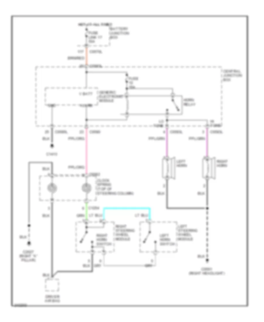
Horn Wiring Diagram for Land Rover Discovery 3 2006
List of elements for Horn Wiring Diagram for Land Rover Discovery 3 2006:
- Alarm
- Battery junction box
- C0082
- C0561 (right headlight)
- C0570l
- C0580
- C0583l
- C0585l
- C1254
- C1413
- C2627 (right "a" pillar)
- Central junction box
- Clock spring (top of steering column)
- Driver air bag
- Fuse 15a
- Fuse link 17 50a
- Generic electronic module
- Gnd
- Hi tone
- Horn relay
- Hot at all times
- Left horn
- Left horn switch
- Left steering wheel module
- Lo tone
- Right horn
- Right horn switch
- Right steering wheel module
- V batt
INSTRUMENT CLUSTER
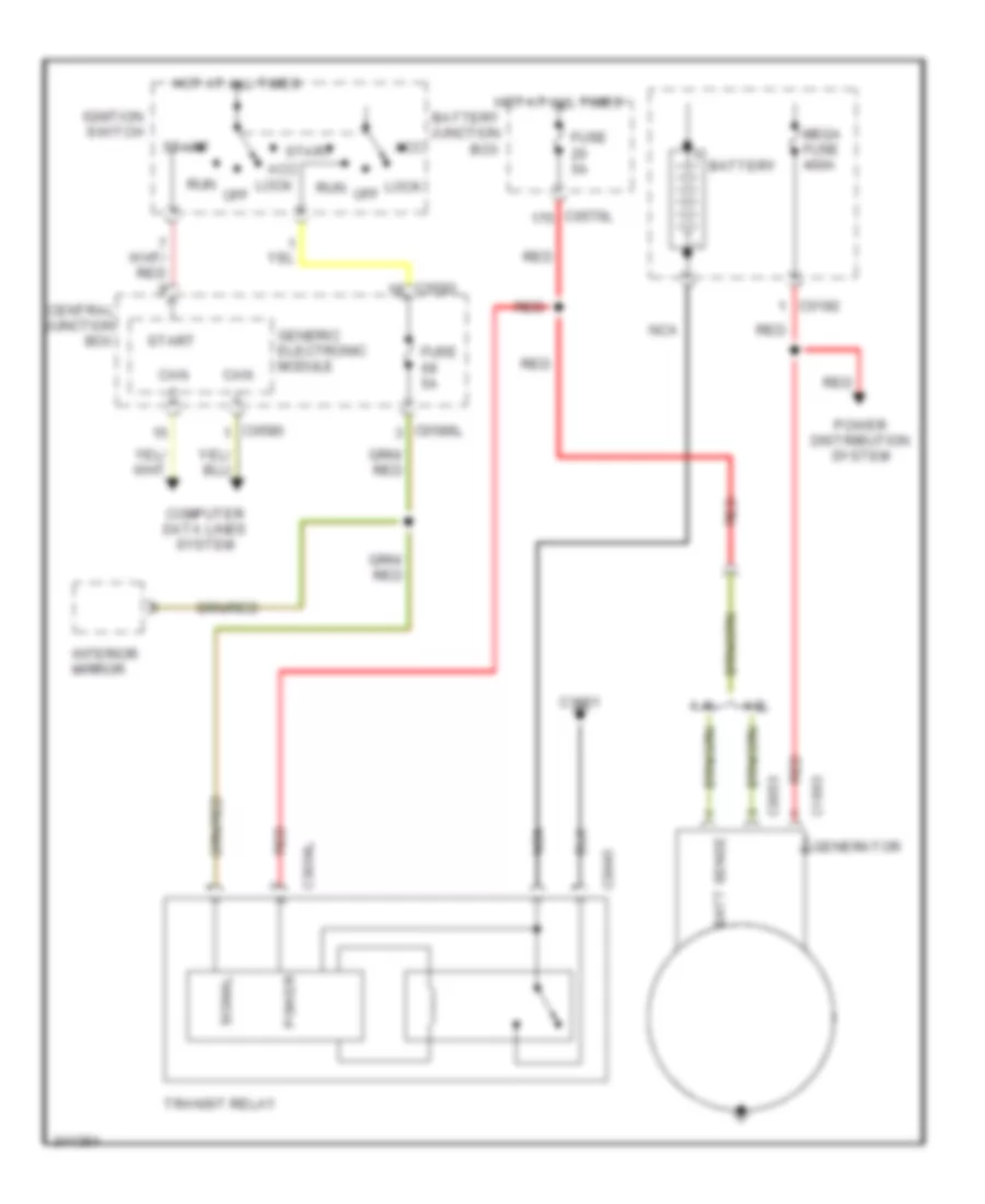
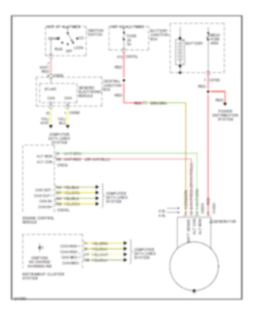
Instrument Cluster & Message Center Wiring Diagram for Land Rover Discovery 3 2006
List of elements for Instrument Cluster & Message Center Wiring Diagram for Land Rover Discovery 3 2006:
- 4cas warning ind
- Abs ind
- Alarm
- Anti-theft alarm warning ind
- Audio head unit
- Automatic temperature control module
- Belt minder mat
- Belt minder sens
- Brake fluid level sens
- Brake fluid level switch (at left rear of engine compt, on top of brake fluid reservoir)
- Braking system/pad wear warning ind
- C0082
- C0560 (right headlight)
- C0580
- C0582
- C0586l
- C1254
- C2562 (under center console)
- C2627 (right "a" pillar)
- C2628 (right "a" pillar)
- C2922 (base of left "d" pillar)
- Can +
- Can -
- Can high +
- Can high -
- Can med +
- Can med - can med -
- Central junction fuse box
- City mode ind
- Clock spring (top of steering column)
- Computer data lines system
- Display unit
- Door opening warning ind
- Dsc ind
- Ect warning ind
- Electric park brake ind (amber)
- Electric park brake ind (red)
- Ems warning ind
- Engine coolant level sensor (at left front of engine compt)
- Engine coolant level warning ind
- Engine coolant temperature gauge
- Ffbh ind
- Fr fog
- Front fog lamps ind
- Fuel gauge
- Fuel tank unit
- Fuel tank unit (on top of fuel tank)
- Fuse 5a
- Generic electronic module
- Glow plug ind
- Gnd
- Hdc active warning lamp
- Hdc fault ind
- Headlights system
- Hot at all times
- Hot in on or start
- Ign
- Ignition/no charge warning ind
- Illum
- Instrument cluster
- Interior lights system
- Left steering wheel module
- Left turn signal ind
- Lf dat output
- Lf in input
- Low fuel ind
- Low range ind
- Low washer fluid ind
- Low washer fluid level sensor (on side of washer fluid reservoir)
- Main beam ind
- Mil ind
- Odometer
- Oil press sw
- Oil pressure switch (at left front of engine compt)
- Oil pressure warning ind
- Over speed ind
- Pad wear sens
- Pad wear sensor (in right rear wheelwell)
- Pad wear sensor (left front wheelwell)
- Parking brake
- Parking brake module (under center of vehicle)
- Radio frequency receiver (center of headliner)
- Rear fog lamps ind
- Red
- Rf rx input
- Right turn signal ind
- Rr fog
- Safety belt warning ind
- Sounder
- Speed control ind
- Speedometer
- Srs warning ind
- Steering column lighting switch
- Sunlight sensor
- Tachometer
- Tpms ind (red w/ low line only)
- Tpms warning ind
- Trailer ind
- Transfer box overheat ind
- Transmission warning ind
- Transponder coil (under center console)
- Trip computer
- V batt
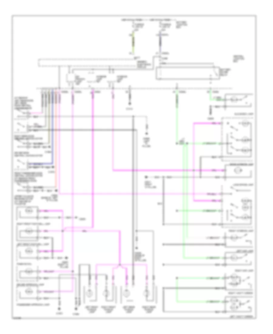
INTERIOR LIGHTS
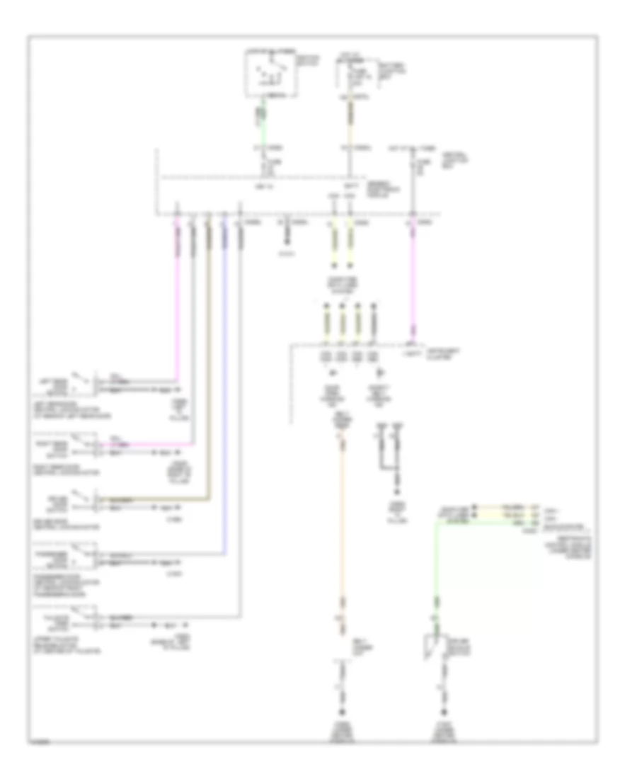
Courtesy Lamps Wiring Diagram for Land Rover Discovery 3 2006
List of elements for Courtesy Lamps Wiring Diagram for Land Rover Discovery 3 2006:
- (at rear of left rear door) left rear door central locking motor
- 40a
- Ap- proach lamp fet
- Batt
- Battery junction box
- Battery saver relay
- C0570l
- C0582
- C0583l
- C0585l
- C0809 (base of right "b" pillar)
- C0811 (right "a" pillar)
- C1413
- C1964
- C1970
- C2565 (left "c" pillar)
- C2627 (right "a" pillar)
- C2630
- C2922 (base of left "d" pillar)
- Central junction box
- Driver approach lamp
- Driver door central locking motor
- Front interior lamp
- Front passenger door central locking motor (at rear of front passenger's door)
- Fuse 10a
- Fusible link 15
- Fusible link 16
- Generic electronic module
- Glove box lamp
- Hot at all times
- Interior lamp fet
- Left front footwell lamp
- Left front puddle lamp
- Left map lamp
- Left rear puddle lamp
- Left vanity mirror
- Load space lamp
- Passenger approach lamp
- Passive coil
- Rear interior lamp
- Right front footwell lamp
- Right front puddle lamp
- Right map lamp
- Right rear door central locking motor
- Right rear puddle lamp
- Right vanity mirror
- Upper tailgate release motor (at center of tailgate)
Instrument Illumination Wiring Diagram (1 of 2) for Land Rover Discovery 3 2006
List of elements for Instrument Illumination Wiring Diagram (1 of 2) for Land Rover Discovery 3 2006:
- 58d
- Audio head unit
- Auto
- Auto lights relay
- Batt
- Battery junction box
- Break down
- C0074
- C0082
- C0089
- C0570l
- C0580
- C0582
- C0583l
- C0585l
- C0586l
- C0807 (left or right kick panel)
- C1254
- C1354
- C1413
- C2105
- C2627 (right "a" pillar)
- C2628 (right "a' pillar)
- C2629
- C2630
- C2645 (under right side of headliner)
- C2646
- C2819
- C2825
- Can +
- Can -
- Can h
- Can l
- Center facia pack switch
- Central junction box
- Clock spring (top of steering column)
- Computer data lines system
- Dimming switch
- Dip
- Driver air bag
- Dsc switch
- Emergency
- Front alert switch
- Front cigar lighter
- Fuse 10a
- Fuse 5a
- Fusible link 16 40a
- General illum
- Generic electronic module
- Hazard warning switch
- Hot at all times
- Hot in run
- Hot in run & acc
- Information
- Instrument cluster
- Left steering wheel module
- Lighting control switch
- Line bus
- Master lock switch
- Master unlock switch
- Navigation system module
- Passenger airbag disable indicator
- Pdc switch
- Phone
- Pnk
- Power tops & memory systems
- Rain/ambient light sensor (on top center of windshield, behind rear view mirror)
- Red
- Right steering wheel module
- Sunlight sensor
- Switch illum
- To driver door window switch (diagram 2 of 2)
- Touch screen display
- Tpm input switch
- Wiper/ washer system
Instrument Illumination Wiring Diagram (2 of 2) for Land Rover Discovery 3 2006
List of elements for Instrument Illumination Wiring Diagram (2 of 2) for Land Rover Discovery 3 2006:
- (base of right "b" pillar) c0809
- (left "c" pillar) c2565
- Air suspension
- Automatic gearbox selector indicator lamp
- Automatic temperature control module
- C0081
- C0343
- C0357
- C0811 (right "a" pillar)
- C1629
- C1964
- C1970
- C1975
- C2598 (base of right "b" pillar)
- C2629
- C2655
- C2712 (left kick panel)
- Can +
- Can -
- Center console switch pack
- Computer data lines system
- Driver door window switch
- Electric park brake switch (under center console)
- From front cigar lighter (diagram 1 of 2)
- Front interior lamp
- Gnd
- Hi/low ratio
- Hill decent switch
- Isolation window lift switch
- Left headphone unit
- Left rear heated seat switch
- Left rear window switch
- Passenger door window switch
- Right headphone unit
- Right rear heated seat switch
- Right rear window switch
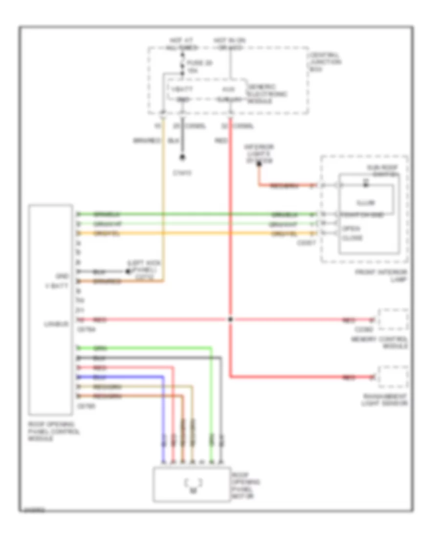
- Roof opening panel control module
- Selector mechanism (under center console)
- Sun roof switch
- Terrain optimization switch
- W/ headphones
- W/o headphones
- Waterfall lighting led
MEMORY SYSTEMS
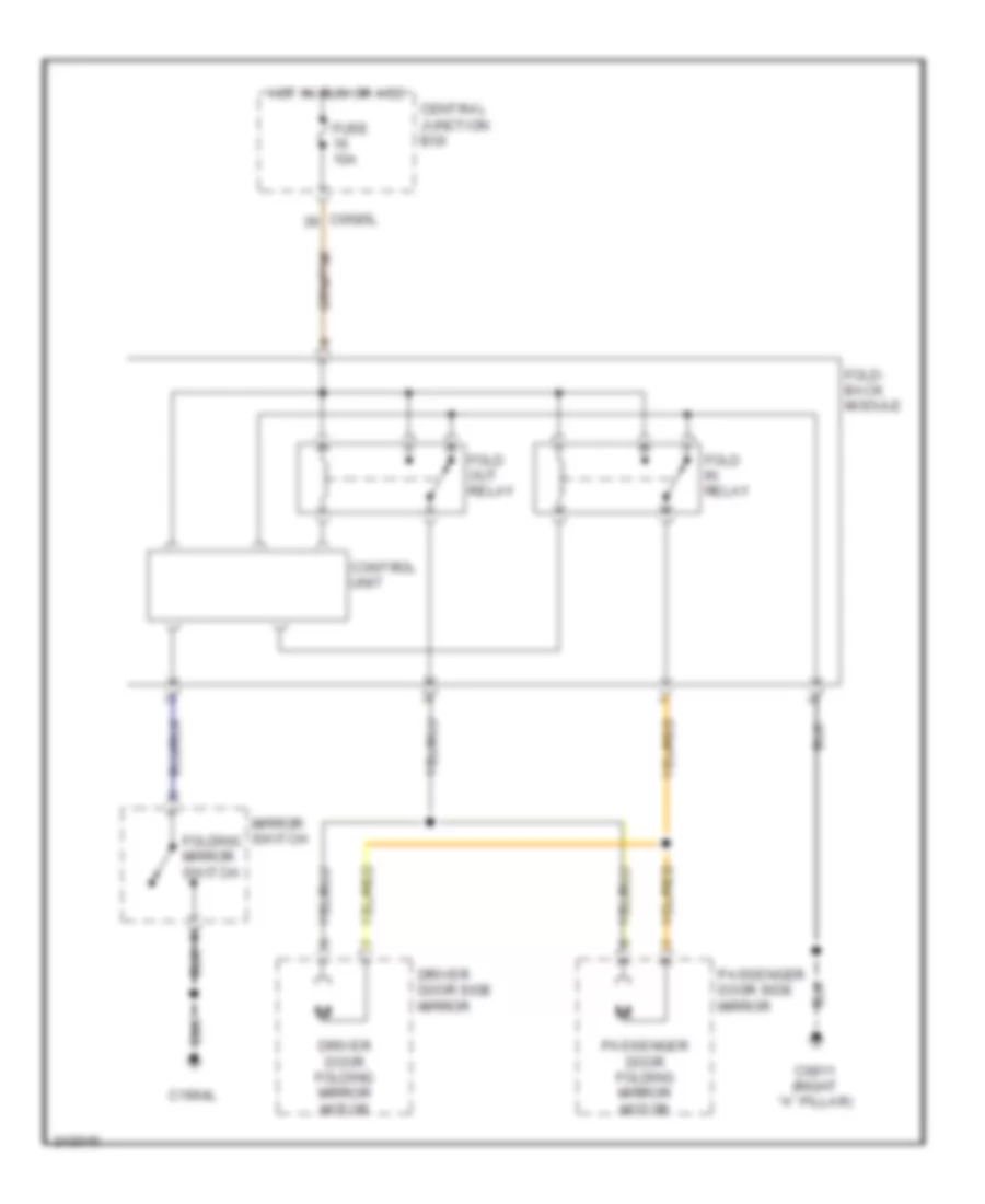
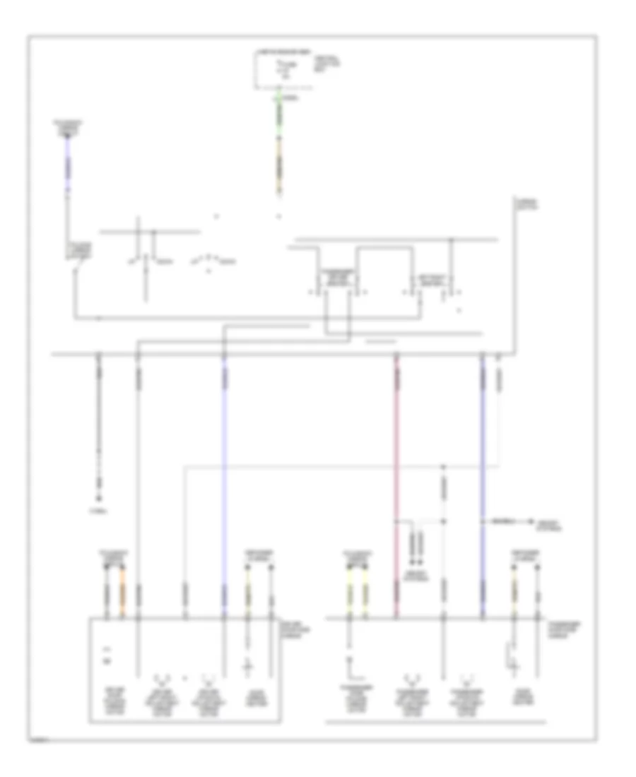
Memory Mirrors Wiring Diagram for Land Rover Discovery 3 2006
List of elements for Memory Mirrors Wiring Diagram for Land Rover Discovery 3 2006:
- (bare end wire)
- C0324
- C0352
- C0353
- C0444
- C0560 (right headlight)
- C0585l
- C0586l
- C0807 (left or right kick panel)
- C1964l
- C2382
- C2383
- C2385
- Central junction box
- Defogger system
- Door mirror heater
- Down
- Driver door folding mirror motor
- Driver door side mirror
- Driver left/right adjustment mirror motor
- Driver up/down adjustment mirror motor
- Fold-back mirrors circuit
- Folding mirror switch
- Fuse 30a
- Fuse 5a
- Generic electronic module
- Hot at all time
- Hot in run or acc
- Left
- Left mirror adjustment switch
- Left/ right
- Lin bus gnd
- Memory control module
- Mirror switch
- Mirrors system
- Mirrors system (fold-back mirror circuit)
- Passenger door folding mirror motor
- Passenger door side mirror
- Passenger left/right adjustment mirror motor
- Passenger up/down adjustment mirror motor
- Power gnd
- Rain/ambient light sensor
- Red
- Right
- Right mirror adjustment switch
- Roof opening panel control module
- Sjb lin
- Up/ down
- V batt
- Wiper/ washer system
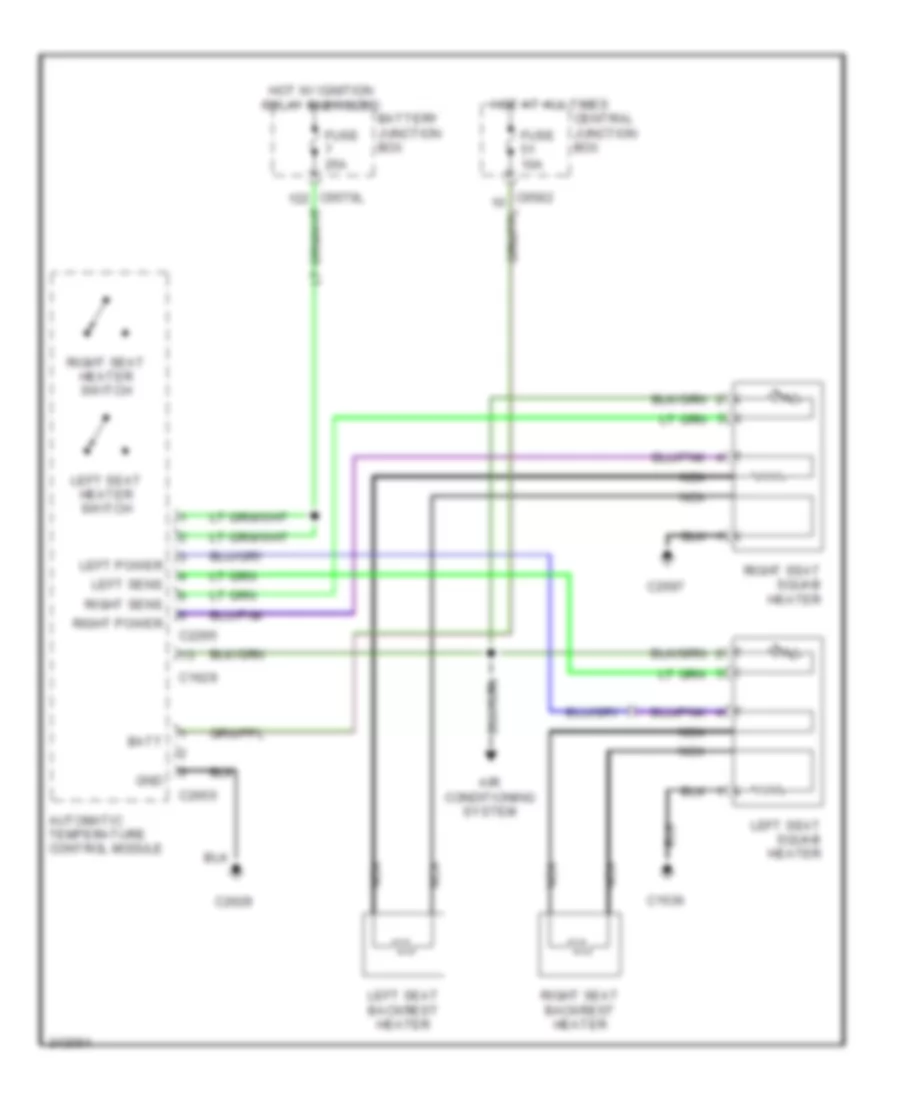
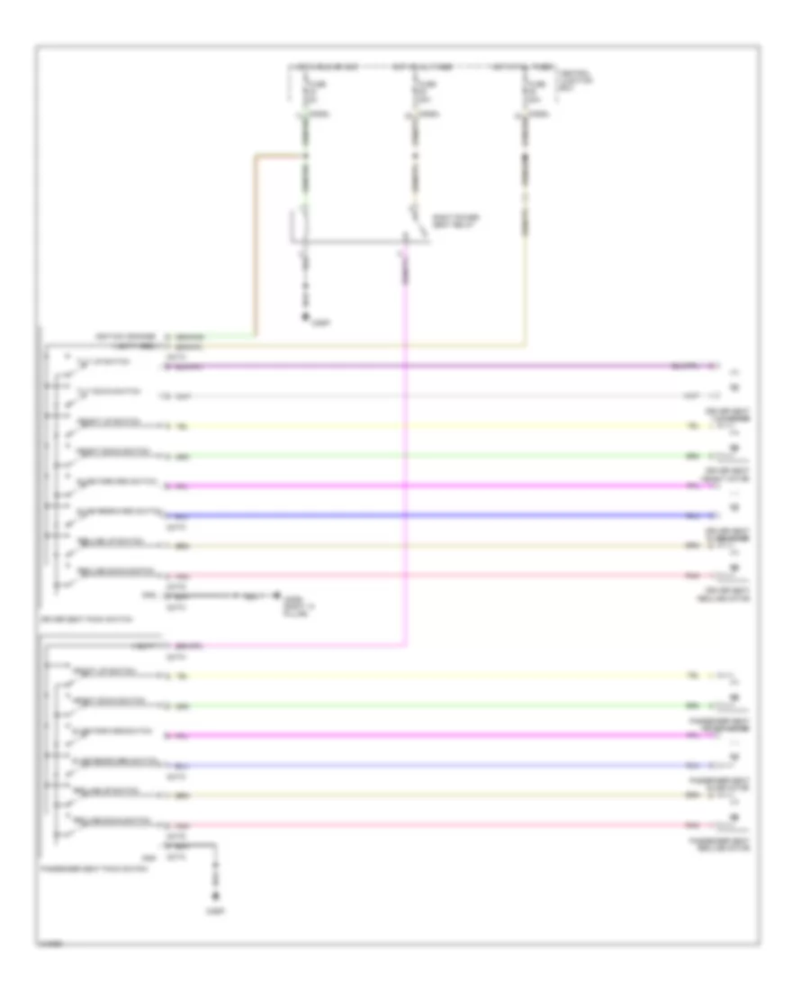
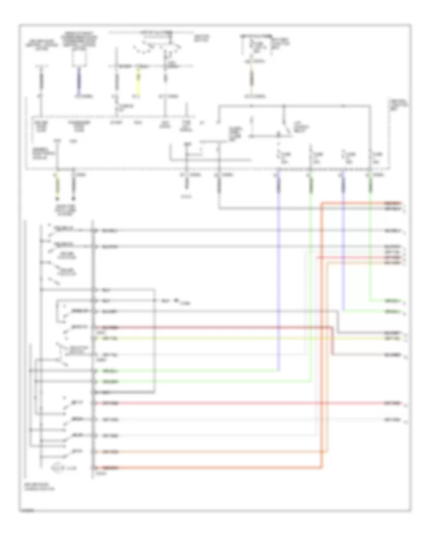
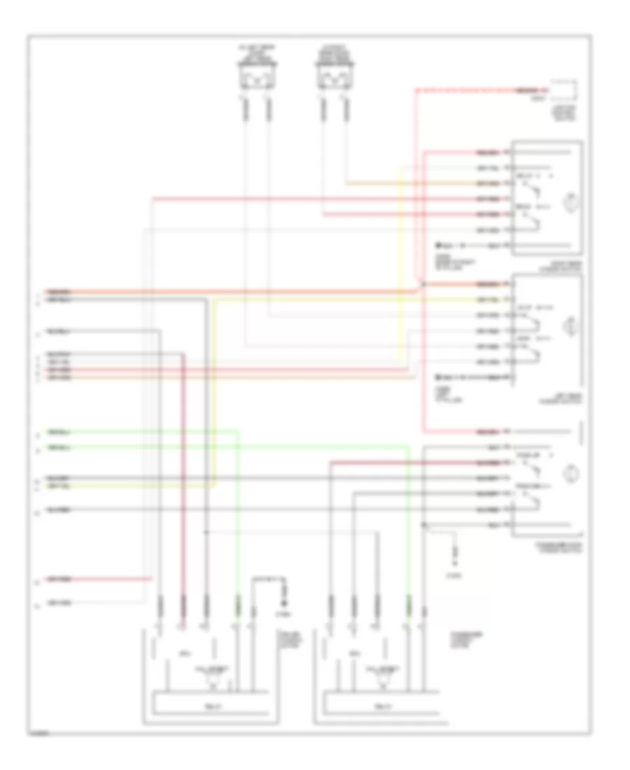
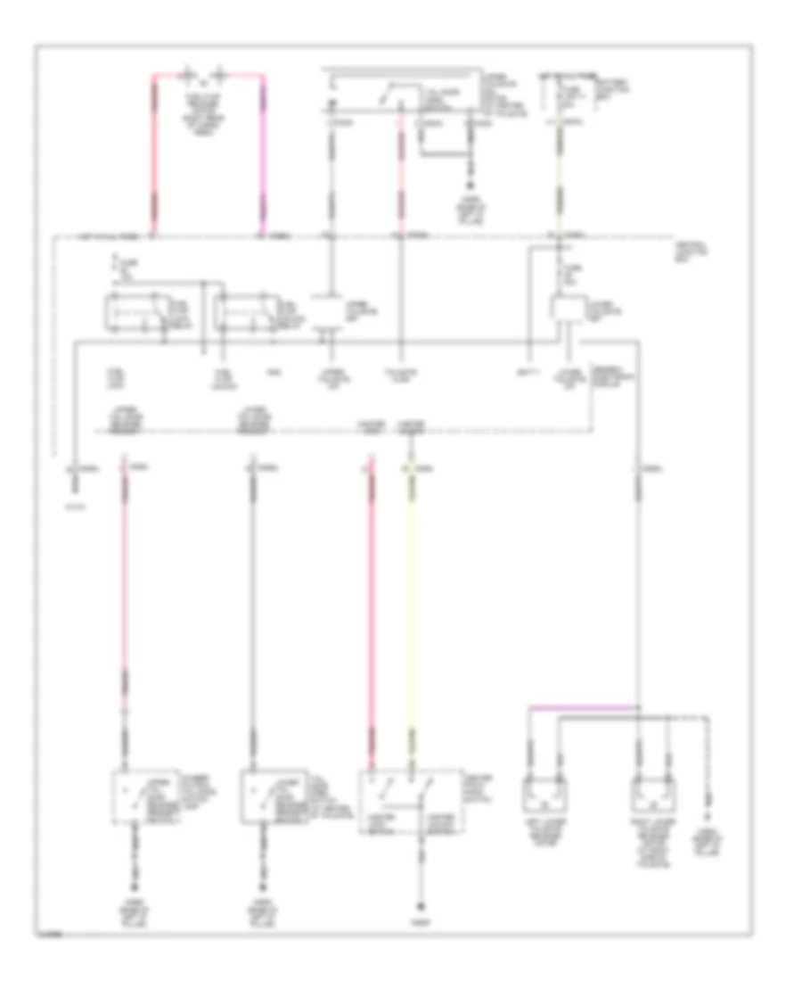
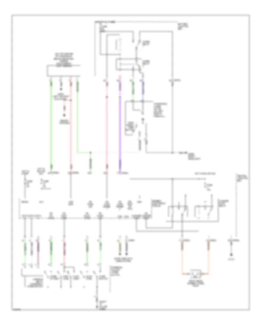
Memory Seat Wiring Diagram for Land Rover Discovery 3 2006
List of elements for Memory Seat Wiring Diagram for Land Rover Discovery 3 2006:
- (bare end wire)
- (pin 1-6 not used)
- C0560 (right headlight)
- C0774
- C2381
- C2382
- C2383
- C2384
- C2385
- C2597
- C2930
- C2931
- Central junction box
- Driver seat pack switch
- Driver seat recline motor
- Driver seat tilt motor
- Drivers seat height motor
- Drivers seat slide motor
- Electronic gnd
- Fuse 30a
- Fuse 5a
- Gnd 1
- Gnd 2
- Hall sense gnd
- Height
- Height down
- Height down switch
- Height sense
- Height up
- Height up switch
- Hot at all times
- Hot in run or acc
- Lin bus gnd
- Memory 1
- Memory 2
- Memory 3
- Memory control module
- Memory store
- Mirrors system
- Passenger seat height motor
- Passenger seat pack switch
- Passenger seat recline motor
- Passenger seat slide motor
- Pnk
- Power gnd
- Recline
- Recline down switch
- Recline lower
- Recline raise
- Recline sense
- Recline up switch
- Red
- Right power seat relay
- Seats system
- Sjb lin
- Slide
- Slide backward
- Slide forward
- Slide forward switch
- Slide rearward switch
- Slide sense
- Tilt
- Tilt down
- Tilt sense
- Tilt up
- V batt
NAVIGATION
Navigation Wiring Diagram (1 of 3) for Land Rover Discovery 3 2006
List of elements for Navigation Wiring Diagram (1 of 3) for Land Rover Discovery 3 2006:
- (pin 13-17 not use)
- (pin 2-6 not use)
- (pin 23-29 not used)
- (pin 7-13 not used)
- Abs module (left rear of engine compartment)
- Acc
- Am/fm diversity antenna amplifier (rear of headliner)
- Ant power
- Audio +
- Audio -
- Audio gnd
- Audio head unit
- Av input panel
- Bat
- Batt
- Battery junction box
- C0082
- C0506l
- C0570l
- C0582
- C0583l
- C1254
- C1354
- C1848
- C2105
- C2113
- C2114
- C2115
- C2218
- C2219
- C2236
- C2554
- C2598 (base of right "b" pillar)
- C2626
- C2645 (under right side of headliner)
- C2646
- C2661
- C2819
- C2820
- C2823
- C2825
- Can +
- Can -
- Can h
- Can l
- Central junction box
- Channel down
- Channel up
- Clock spring (top of steering column)
- Computer data lines system
- Dimming
- Display
- Ent ctrl
- Fm antenna amplifier
- Front interior lamp
- Fuse 10a
- Fuse 15a
- Fuse 5a
- Fusible
- Gnd
- Gps antenna
- Gvif +
- Gvif -
- Gvif shield
- Hot at all times
- Infotainment relay
- Interior lights system
- Left steering wheel module
- Link 18 50a
- Mic +
- Mic -
- Mic scr
- Mic+
- Mic-
- Microphone telephone
- Mode
- Most in
- Most out
- Navigation system module
- Nca
- Phone end
- Phone send
- Power
- Private can h
- Private can l
- Red
- Rf in
- Rf input
- Rf out
- Scr
- Sws 1
- Touch screen display
- V batt
- Vehicle speed
- Volume +
- Volume -
- W/ navi- gation
- W/ navigation
- W/o navi- gation
Navigation Wiring Diagram (2 of 3) for Land Rover Discovery 3 2006
List of elements for Navigation Wiring Diagram (2 of 3) for Land Rover Discovery 3 2006:
- (behind right rear quarterpanel) tmc receiver
- (pin 19-32 not used)
- Aci
- Aud 2 in l+
- Aud 2 in l-
- Aud 2 in r+
- Aud 2 in r-
- Aud in l+
- Aud in l-
- Aud in r+
- Aud in r-
- Batt
- C2106
- C2117
- C2154
- C2155
- C2157
- C2158
- C2228
- C2646
- C2647
- C2648
- C2669
- C2670
- C2671
- C2776
- C2777
- C2778
- C2789
- C2987
- C3160
- Cvbs 1 in
- Cvbs 1 in gnd
- Cvbs 2 in
- Cvbs 2gnd
- Cvbs gnd
- Cvbs out
- Dab antenna
- Dab antenna amplifier
- Dab/sdar
- Dab/sdars tuner module
- Gnd
- Ign
- Information not available
- Left tv antenna
- Most in
- Most out
- Nca
- Pci
- Phone ear+
- Phone ear-
- Phone mic+
- Phone mic-
- Phone/charge gnd
- Power
- Red
- Rf out
- Right tv antenna
- Sat
- Sdars antenna
- Ser rx+
- Ser rx-
- Ser tx+
- Ser tx-
- Telephone antenna
- Telephone base plate
- Telephone control module
- Terr
- Tmc/ vics antenna amplifier
- To power ice amplifier (diagram 3 of 3)
- Tv tuner module
- V batt
- V charge
- Wake phone
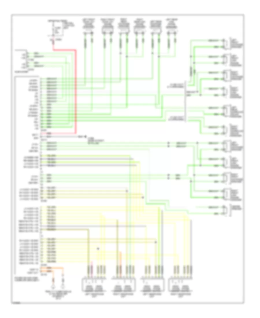
Navigation Wiring Diagram (3 of 3) for Land Rover Discovery 3 2006
List of elements for Navigation Wiring Diagram (3 of 3) for Land Rover Discovery 3 2006:
- +ve
- -ve
- Batt
- C0491
- C0492
- C0493
- C0582
- C1352
- C1968 (base of right "b" pillar)
- C2102
- C2414
- C2702
- Center speaker
- Center+
- Center-
- Central junction box
- From tv tuner module & tmc receiver (diagram 2 of 3)
- Fuse 30a
- Gnd
- Head- phone socket
- Head- phone switch
- Hot at all times
- Left front door low range speaker
- Left front high range speaker
- Left front mid range speaker
- Left headphone unit
- Left rear high range speaker
- Left rear mid range speaker
- Left rear surround sound speaker
- Lf bass+
- Lf bass-
- Lf mh+
- Lf mh-
- Lh audio +ve
- Lh audio +ve lh audio +ve
- Lh audio -ve gnd
- Lr spk+
- Lr spk-
- Ls+
- Ls-
- Most in
- Most out
- Power ice amplifier (under driver's seat)
- Red
- Remote ctrl +ve
- Remote ctrl -ve
- Rf bass+
- Rf bass-
- Rf mh+
- Rf mh-
- Rh audio +ve
- Rh audio +ve rh audio +ve
- Rh audio -ve gnd
- Right front door low range speaker
- Right front high range speaker
- Right front mid range speaker
- Right headphone unit
- Right rear high range speaker
- Right rear mid range speaker
- Right rear surround sound speaker
- Rr spk+
- Rr spk-
- Rs+
- Rs-
- Subwoofer
- W/ 240 watt & 9 speakers
- W/ 550 watt & 13 speakers
Parking Assistant Wiring Diagram for Land Rover Discovery 3 2006
List of elements for Parking Assistant Wiring Diagram for Land Rover Discovery 3 2006:
- C0586l
- C0957
- C0958
- C1457
- C2568 (base of left "d" pillar)
- C2629
- Center facia pack switch
- Central junction box
- Computer data lines system
- Front pdc switch
- Fuse 5a
- Hot in run
- Left front inner parking aid sensor
- Left front outer parking aid sensor
- Left rear inner parking aid sensor
- Left rear outer parking aid sensor
- Parking aid control module
- Rear parking aid speaker
- Red
- Right front inner parking aid sensor
- Right front outer pdc sensor
- Right rear inner parking aid sensor
- Right rear outer parking aid sensor
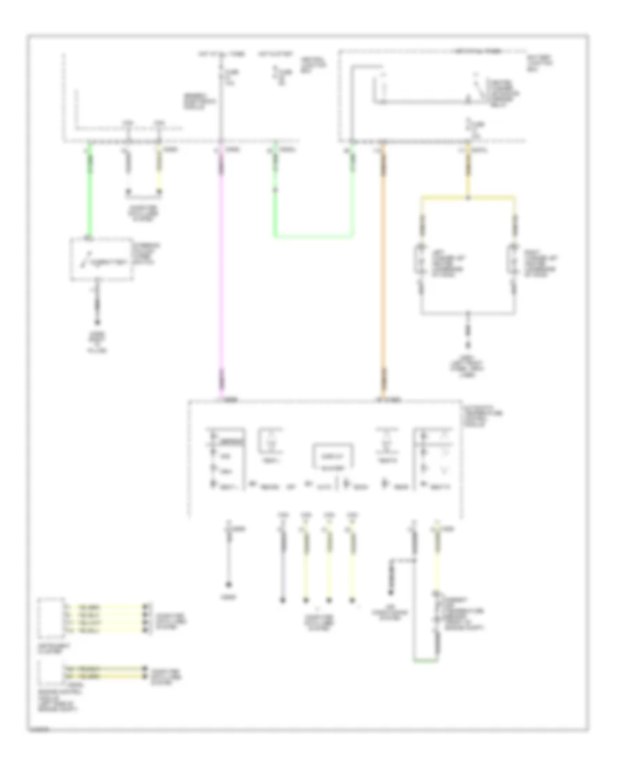
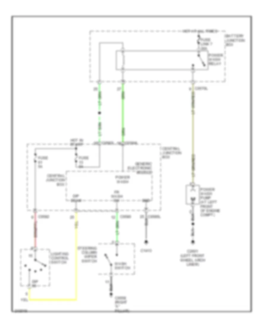
POWER DISTRIBUTION
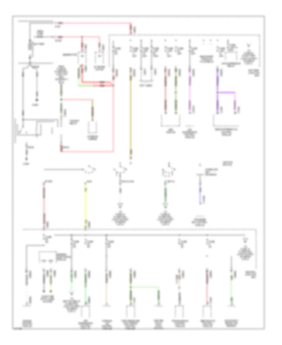
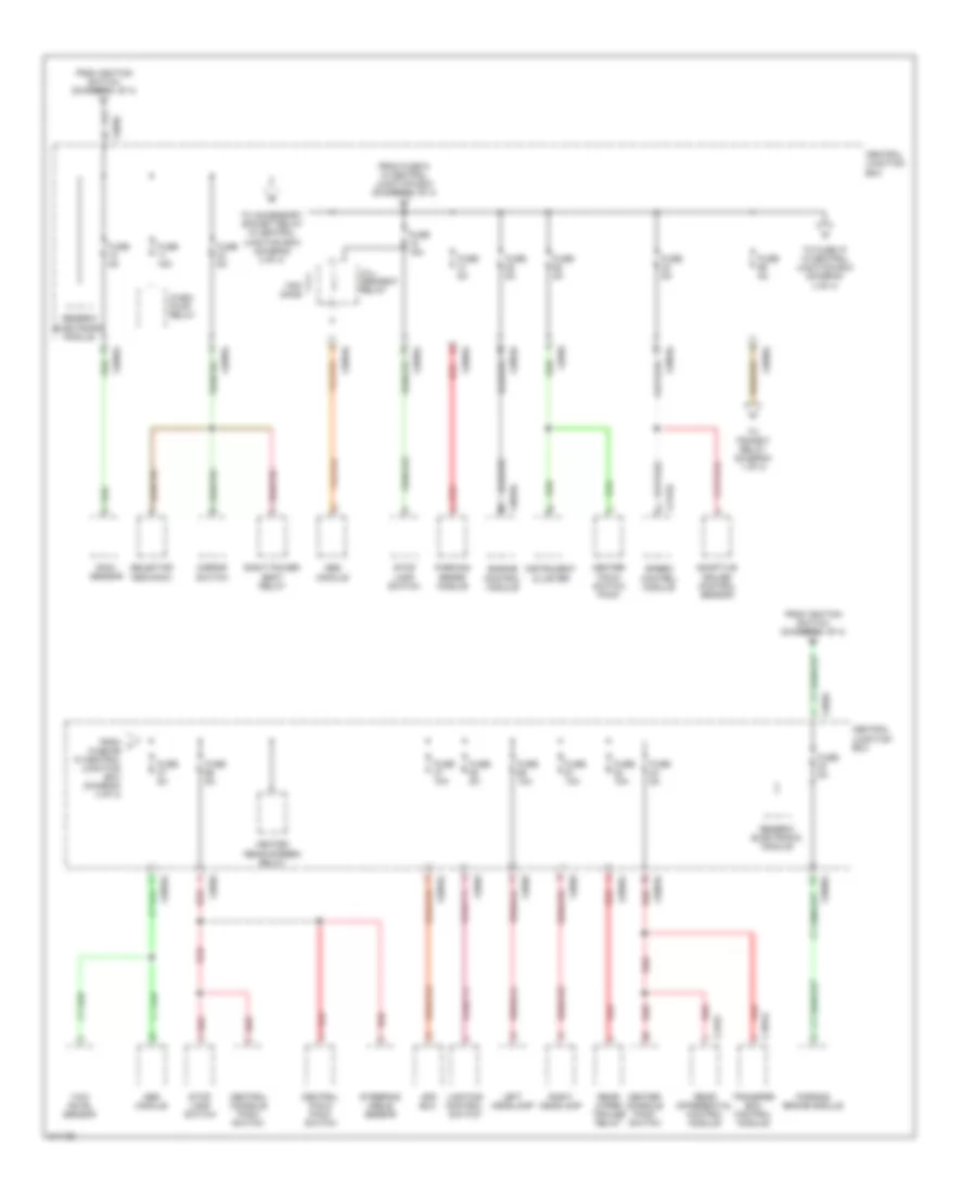
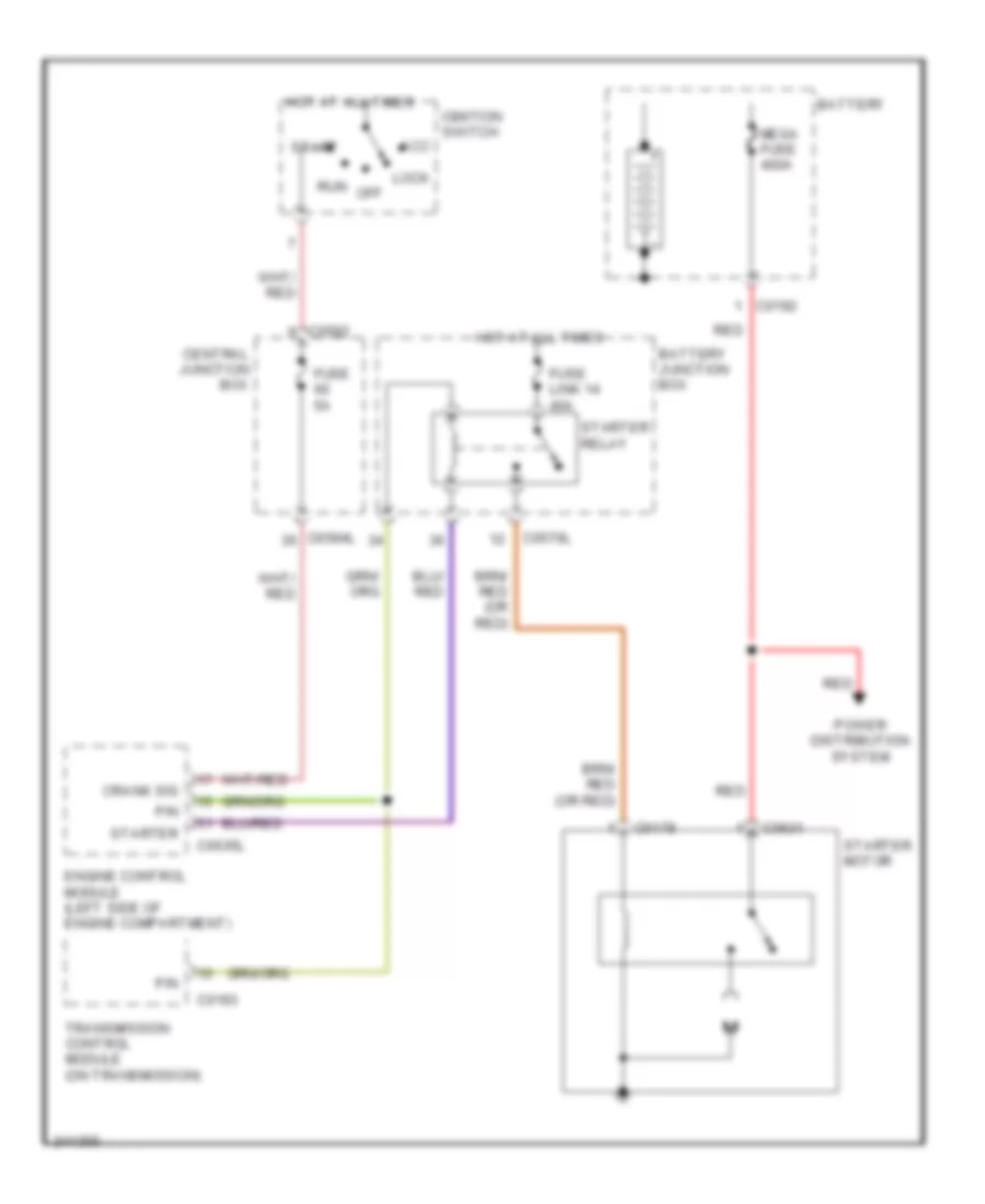
Power Distribution Wiring Diagram (1 of 4) for Land Rover Discovery 3 2006
List of elements for Power Distribution Wiring Diagram (1 of 4) for Land Rover Discovery 3 2006:
- (not used)
- Abs module
- Air suspension control module
- Air suspension relay
- Battery
- Battery junction box
- C0045
- C0053
- C0192
- C0570l
- C0571
- C0572
- C0580
- C0582
- C0583l
- C0584l
- C0585l
- C0586l
- C0631
- C0632
- C0635l
- C0867l
- C1319l
- C1537
- C164
- C1649
- C1661
- C1893
- C2163
- C2321l
- C3034l
- Can +
- Can -
- Center facia pack switch
- Central junction box
- Computer data lines system
- Engine control module
- From fuse 69 in central junction box (diagram 4 of 4)
- Fuse 20a
- Fuse 25a
- Fuse 5a
- Fuse link 10 60a
- Fuse link 150a
- Fuse link 30a
- Fuse link 40a
- Fuse link 80a
- Generator
- Generic electronic module
- Ignition switch
- Interior mirror
- Interlock key solenoid
- Key-in
- Mega fuse 400a
- Nca
- Occupancy detector sensor
- Parking aid control module
- Rear differential control module
- Red
- Restraints control module
- Run
- Run & acc
- Secondary air/glow plug relay
- Start
- Starter motor
- Tire pressure monitoring control module
- To fuse 15 in central junction box (diagram 4 of 4)
- To fuse 18 in central junction box (diagram 4 of 4)
- To fuse 30 in battery junction box (diagram 2 of 4)
- To fuse 40 in central junction box (diagram 4 of 4)
- To ignition relay in central junction box (diagram 2 of 4)
- Transfer box control module
- Transit relay
- Transmission control module
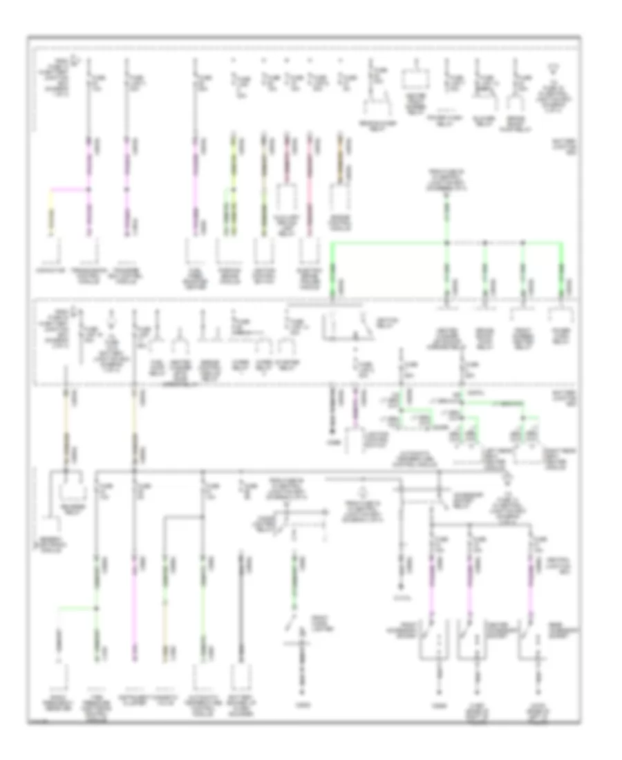
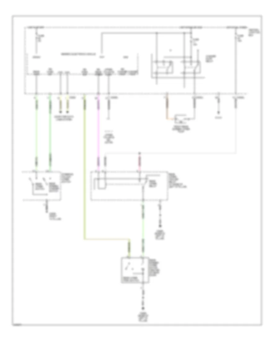
Power Distribution Wiring Diagram (2 of 4) for Land Rover Discovery 3 2006
List of elements for Power Distribution Wiring Diagram (2 of 4) for Land Rover Discovery 3 2006:
- Accessory socket relay
- Automatic temperature control module
- Auxiliary driving lamp relay
- Battery backed up alarm sounder
- Battery junction box
- Blower relay
- Brake boost pump relay
- C0560
- C0570l
- C0582
- C0583l
- C0585l
- C0635l
- C0926
- C1413l
- C1537
- C1854l
- C1967 (base of right "b" pillar)
- C2382
- C2626
- C2630
- C2655
- C2700 (base of left "d" pillar)
- Capacitor
- Center accessory socket
- Central junction box
- Cigar lighter relay
- Electric brake trailer module
- Engine control module
- Engine control module relay
- From c fuse 10 in battery junction box (diagram 1 of 4)
- From f fuse 24 in battery junction box (diagram 2 of 4)
- From fuse 28 in central junction box (diagram 1 of 4)
- From fuse 33 in central junction box (diagram 4 of 4)
- From fuse 55 in central junction box (diagram 3 of 4)
- Front accessory socket
- Front cigar lighter
- Front screen heated relay
- Fuel fired booster heater
- Fuel pump relay
- Fuse 10a
- Fuse 15a
- Fuse 20a
- Fuse 25a
- Fuse 30a
- Fuse 5a
- Fuse link 12 40a
- Fuse link 14 40a
- Fuse link 16 40a
- Fuse link 2 30a
- Fuse link 3 30a
- Fuse link 30a
- Fuse link 50a
- Fuse link 6 30a
- Fuse link 7 30a
- Generic electronic module
- Heated front screen relay
- Heated washer jets/ door mirror relay
- Heated washer jets/door mirrors relay
- Ignition relay
- Instrument cluster
- Left rear seat heater module
- Lighting control switch
- Magnetic valve
- Parking brake module
- Power wash relay
- Radio frequency receiver
- Rear accessory socket
- Rear blower relay
- Reverse relay
- Right rear seat heater module
- Starter relay
- Tire pressure monitoring control module
- To fuse 13 in central junction box (diagram 3 of 4)
- To fuse 15 in battery junction box (diagram 3 of 4)
- To fuse 16 in central junction box (diagram 2 of 4)
- Transfer box control module
- Transmission control module
- Wiper relay
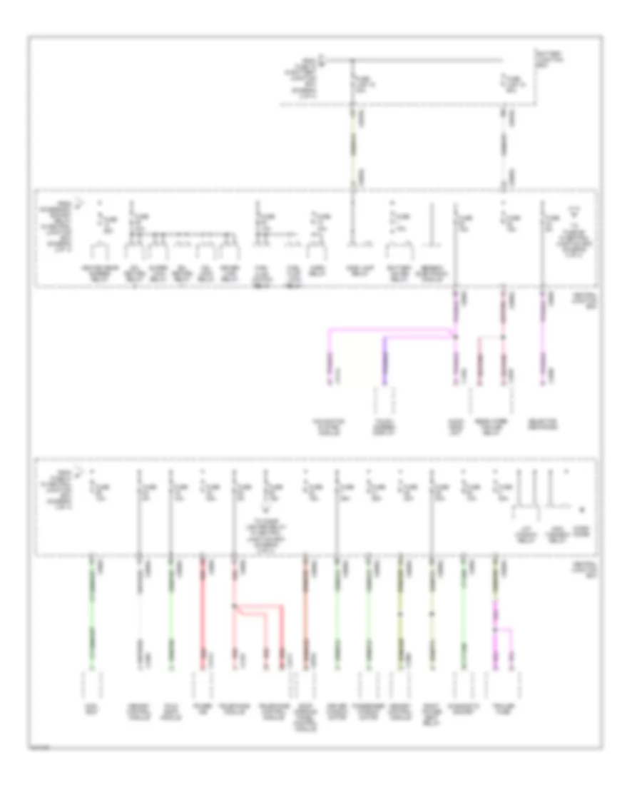
Power Distribution Wiring Diagram (3 of 4) for Land Rover Discovery 3 2006
List of elements for Power Distribution Wiring Diagram (3 of 4) for Land Rover Discovery 3 2006:
- Audio head unit
- Battery junction box
- Battery saver relay
- C0570l
- C0582
- C0583l
- C0585l
- C0784
- C1354
- C2114
- C2157
- C2382
- C2385
- C2414
- C2658
- C2777
- C2937
- Cdl lock relay
- Cdl return relay
- Central junction box
- Cool box
- Diagnostic socket
- Driver lock relay
- Driver window motor
- Fold back module
- From g fuse 16 in battery junction box (diagram 2 of 4)
- From o accessory socket relay in central junction box (diagram 2 0f 4)
- From p fuse 44 in central junction box (diagram 3 of 4)
- Fuel flap lock relay
- Fuel flap unlock relay
- Fuse 10a
- Fuse 15a
- Fuse 25a
- Fuse 30a
- Fuse 5a
- Fuse link 15 40a
- Fuse link 18 50a
- Generic electronic module
- Heated rear screen relay
- Horn relay
- Info- tainment relay
- Lift window relay
- Memory control module
- Micro diode
- Navigation system module
- Passenger window motor
- Power ice
- Rear wiper trailer relay
- Red
- Right power seat relay
- Roof opening panel control module
- Selector mechanism
- Side lamp relay
- Super- lock relay
- Telephone control module
- Telephone module
- To cigar lighter relay in central junction box (diagram 2 of 4)
- To fuse 59 in central junction box (diagram 3 of 4)
- Touch screen display
- Trailer fuse
Power Distribution Wiring Diagram (4 of 4) for Land Rover Discovery 3 2006
List of elements for Power Distribution Wiring Diagram (4 of 4) for Land Rover Discovery 3 2006:
- Abs module
- Adaptive cruise control sensor
- Afs ecu
- C0582
- C0583l
- C0585l
- C0586l
- C0635l
- C1854l
- C2145l
- C2163
- Center console pack switch
- Center facia switch pack
- Central console pack switch
- Central facia pack switch
- Central junction box
- Engine control module
- From fuse 9 in central junction box (diagram 1 of 4)
- From ignition switch (diagram 1 of 4)
- From t fuse 69 in central junction box (diagram 4 of 4)
- Fuse 10a
- Fuse 15a
- Fuse 5a
- Generic electronic module
- Heated rear screen relay
- Hill descent relay
- Instrument cluster
- Left headlamp
- Lighting control switch
- Mirror switch
- Ohms
- Parking brake module
- Rain sensor
- Rear differential control module
- Rear wiper trailer relay
- Red
- Right headlamp
- Right power seat relay
- Selector mechanic
- Speed control module
- Steering angle sensor
- Stop lamp switch
- To accessory socket relay in central junction box (diagram 2 of 4)
- To fuse 37 in central junction box (diagram 4 of 4)
- To transit relay (diagram 1 of 4)
- Transfer box control module
- Wash pump relay
- Yaw rate sensor
POWER DOOR LOCKS
Power Door Locks Wiring Diagram (1 of 2) for Land Rover Discovery 3 2006
List of elements for Power Door Locks Wiring Diagram (1 of 2) for Land Rover Discovery 3 2006:
- (center of headliner) radio frequency receiver
- (not used w/ v101)
- Alarm led
- Aux
- Batt
- Battery junction box
- C0570l
- C0580
- C0582
- C0583l
- C0585l
- C0586l
- C0809 (base of right "b" pillar)
- C1413l
- C1964
- C1970
- C2565 (left "c" pillar)
- C2922 (base of left "d" pillar)
- Can +
- Can -
- Cdl lock o/p
- Cdl lock relay
- Cdl return relay
- Central junction box
- Computer data lines system
- Crank
- Door key lock switch
- Door lock switch
- Driver ajar
- Driver door central locking motor
- Driver door lock status
- Driver door switch
- Driver lock motor
- Driver lock o/p
- Driver lock relay
- Driver super lock motor
- Fuse 40 5a
- Fuse 49 30a
- Fuse 60 5a
- Fuse link 17 50a
- Generic electronic module
- Gnd
- Hot at all times
- Ign
- Ignition switch
- Instrument cluster
- Key in
- Key-in
- Left lower tailgate release motor
- Left rear door ajar
- Left rear door central locking motor
- Left rear door switch
- Left rear lock motor
- Left rear super lock motor
- Lf in
- Lf out
- Lock
- Lower tailgate fet
- Lower tailgate o/p
- Pass door ajar
- Passenger door central locking motor
- Passenger door switch
- Passenger lock motor
- Passenger super lock motor
- Passive coil
- Red
- Rf in
- Right lower tailgate release motor (at right side of tailgate)
- Right rear door ajar
- Right rear door central locking motor
- Right rear door switch
- Right rear lock motor
- Right rear super lock motor
- Rtn 1 o/p
- Rtn 2 o/p
- Super lock relay
- Super- lock o/p
- Unlock
Power Door Locks Wiring Diagram (2 of 2) for Land Rover Discovery 3 2006
List of elements for Power Door Locks Wiring Diagram (2 of 2) for Land Rover Discovery 3 2006:
- (not used w/ v101)
- 13 pin
- 7 pin
- Bonnet ajar
- C0383
- C0561 (right headlamp)
- C0561 (right headlight)
- C0564 (left front of engine compt)
- C0565
- C0580
- C0582
- C0583l
- C0584l
- C0585l
- C0586l
- C0616
- C1355 (base of right "d" pillar)
- C1964
- C1970
- C2568 (base of left "d" pillar)
- C2629
- C2921
- C2922 (base of left "d" pillar)
- Center facia pack switch
- Central junction box
- Fet
- Flasher
- Fuel flap lock
- Fuel flap lock relay
- Fuel flap release motor (right rear of cargo area)
- Fuel flap unlock
- Fuel flap unlock relay
- Fuse 10a
- Fuse 15a
- Generic electronic module
- Hi tone
- Hood ajar switch (at right rear of engine compt)
- Horn relay
- Horn rly ctrl
- Hot at all times
- Indicator
- Key lock
- Key unlock
- Lamp
- Left
- Left front side
- Left headlamp
- Left horn
- Left ind o/p
- Left indi- cator fet
- Left stop
- Left trailer ind o/p
- Lo tone
- Lower tail door release request
- Lower tail door release request switch
- Master lock
- Master lock switch
- Master unlock
- Master unlock switch
- Number plate & tail door switch lamp
- Pick up trailer
- Pnk/red
- Repeater lamp
- Right front side
- Right headlamp
- Right horn
- Right ind o/p
- Right indi- cator fet
- Right stop
- Right trailer ind o/p
- Right trailer indi- cator fet
- Tail door open switch
- Tailgate ajar
- Trailer
- Turn signal ind/hazard
- Upper tail door release request
- Upper tail door release request switch
- Upper tailgate cdl motor (at center of tailgate)
- Upper tailgate fet
- Upper tailgate o/p
POWER MIRRORS
Electrochromic Mirror Wiring Diagram for Land Rover Discovery 3 2006
List of elements for Electrochromic Mirror Wiring Diagram for Land Rover Discovery 3 2006:
- Battery junction box
- C0193
- C0570l
- C0580
- C0582
- C0583l
- C0585l
- C0586l
- C0807 (left or right kick panel)
- Can h
- Can l
- Central junction box
- Computer data lines system
- Exterior lights system
- Fuse 10a
- Fuse 5a
- Fuse link 16 40a
- Generic electronic module
- Hot at all times
- Hot in run
- Ignition switch
- Interior mirror
- Reverse lamp switch
- Reverse relay
- Run
- Transmission control module (on transmission)
Fold-back Mirrors Wiring Diagram for Land Rover Discovery 3 2006
List of elements for Fold-back Mirrors Wiring Diagram for Land Rover Discovery 3 2006:
- C0585l
- C0811 (right "a" pillar)
- C1964l
- Central junction box
- Control unit
- Driver door folding mirror motor
- Driver door side mirror
- Fold in relay
- Fold out relay
- Fold- back module
- Folding mirror switch
- Fuse 10a
- Hot in run or acc
- Mirror switch
- Passenger door folding mirror motor
- Passenger door side mirror
Power Mirrors Wiring Diagram for Land Rover Discovery 3 2006
List of elements for Power Mirrors Wiring Diagram for Land Rover Discovery 3 2006:
- C0585l
- C1964l
- Central junction box
- Defogger system
- Door mirror heater
- Down
- Driver door folding mirror motor
- Driver door side mirror
- Driver left/right adjustment mirror motor
- Driver up/down adjustment mirror motor
- Fold-back mirror circuit
- Folding mirror switch
- Fuse 5a
- Hot in run or acc
- Left/right switch
- Memory systems
- Mirror switch
- Passenger door folding mirror motor
- Passenger door side mirror
- Passenger left/right adjustment mirror motor
- Passenger up/down adjustment mirror motor
- Passenger/ driver switch
POWER SEATS
Front Seat Heater Wiring Diagram for Land Rover Discovery 3 2006
List of elements for Front Seat Heater Wiring Diagram for Land Rover Discovery 3 2006:
- Air conditioning system
- Automatic temperature control module
- Batt
- Battery junction box
- C1536
- C1629
- C2295
- C2597
- C2629
- C2655
- Central junction box
- Fuse 10a
- Fuse 25a
- Gnd
- Hot at all times
- Hot w/ ignition relay energized
- Left power
- Left seat backrest heater
- Left seat heater switch
- Left seat squab heater
- Left sens
- Nca
- Right power
- Right seat backrest heater
- Right seat heater switch
- Right seat squab heater
- Right sens
Power Seats Wiring Diagram for Land Rover Discovery 3 2006
List of elements for Power Seats Wiring Diagram for Land Rover Discovery 3 2006:
- C0558 (right "a" pillar)
- C0773
- C0774
- C0775
- C2597
- Central junction box
- Driver seat height motor
- Driver seat pack switch
- Driver seat recline motor
- Driver seat slide motor
- Driver seat tilt motor
- Fuse 30a
- Fuse 5a
- Gnd
- Height down switch
- Height up switch
- Hot at all times
- Hot in run or acc
- Ignition (orange)
- Passenger seat height motor
- Passenger seat pack switch
- Passenger seat recline motor
- Passenger seat slide motor
- Pnk
- Recline down switch
- Recline up switch
- Right power seat relay
- Slide forward switch
- Slide rearward switch
- Tilt down switch
- Tilt up switch
- V batt
- V batt (red)
Rear Seat Heater Wiring Diagram for Land Rover Discovery 3 2006
List of elements for Rear Seat Heater Wiring Diagram for Land Rover Discovery 3 2006:
- Battery junction box
- C1412 (base of right "b" pillar)
- C2566 (left "c" pillar)
- C2598 (base of right "b" pillar)
- Fuse 25a
- High
- Hot w/ ignition relay energized
- Interior lights system
- Left rear seat backrest heater
- Left rear seat heat switch
- Left rear seat heater module
- Left rear seat side heater
- Left rear seat squab heater
- Low
- Pnk
- Red
- Right rear seat backrest heater
- Right rear seat heat switch
- Right rear seat heater module
- Right rear seat side heater
- Right rear seat squab heater
POWER TOP/SUNROOF
Power Top/Sunroof Wiring Diagram for Land Rover Discovery 3 2006
List of elements for Power Top/Sunroof Wiring Diagram for Land Rover Discovery 3 2006:
- (left kick panel) c2712
- Aux
- C0357
- C0585l
- C0586l
- C0784
- C0785
- C1413
- C2382
- Central junction box
- Close
- Front interior lamp
- Fuse 20 15a
- Generic electronic module
- Gnd
- Hot at all times
- Hot in on or acc
- Illum
- Interior lights system
- Lin-bus
- Memory control module
- Open
- Rain/ambient light sensor
- Red
- Roof opening panel control module
- Roof opening panel motor
- Sjb lin
- Sun roof switch
- Switch gnd
- V batt
- Vbatt
POWER WINDOWS
Power Windows Wiring Diagram (1 of 2) for Land Rover Discovery 3 2006
List of elements for Power Windows Wiring Diagram (1 of 2) for Land Rover Discovery 3 2006:
- (rear of front passenger's door) passenger door central locking motor
- Acc & run
- Battery junction box
- C0081
- C0343
- C0570l
- C0580
- C0582
- C0583l
- C0585l
- C0586l
- C1413
- C1964
- C2654
- Can +
- Can -
- Central junction box
- Computer data lines system
- Driver auto dn
- Driver auto up
- Driver dn
- Driver door ajar
- Driver door central locking motor
- Driver door window switch
- Driver up
- Fuse 20a
- Fuse 25a
- Fuse 60 5a
- Fuse link 18 50a
- Generic electronic module
- Global open/ close fet
- Gnd
- Hot at all times
- Ignition switch
- Illum
- Isolation switch
- Lift window relay
- Lr dn
- Lr up
- Pass dn
- Pass up
- Passenger door ajar
- Rr dn
- Rr up
- Run
- Start
- Time out signal
Power Windows Wiring Diagram (2 of 2) for Land Rover Discovery 3 2006
List of elements for Power Windows Wiring Diagram (2 of 2) for Land Rover Discovery 3 2006:
- (in left rear door) left rear window motor
- (in right rear door) right rear window motor
- C0041
- C0809 (base of right "b" pillar)
- C1964
- C1970
- C2565 (left "c" pillar)
- Driver window motor
- Ecu
- Hall effect
- Left rear window switch
- Lighting control switch
- Lr dn
- Lr up
- Pass dn
- Pass up
- Passenger door window switch
- Passenger window motor
- Relay
- Right rear window switch
- Rr dn
- Rr up
RADIO
Radio Wiring Diagram, High Line (1 of 3) for Land Rover Discovery 3 2006
List of elements for Radio Wiring Diagram, High Line (1 of 3) for Land Rover Discovery 3 2006:
- (pin 13-17 not use)
- (pin 2-6 not use)
- (pin 23-29 not used)
- (pin 7-13 not used)
- Abs module (left rear of engine compartment)
- Acc
- Am/fm diversity antenna amplifier (rear of headliner)
- Ant power
- Audio +
- Audio -
- Audio gnd
- Audio head unit
- Av input panel
- Bat
- Batt
- Battery junction box
- C0082
- C0506l
- C0570l
- C0582
- C0583l
- C1254
- C1354
- C1848
- C2105
- C2113
- C2114
- C2115
- C2218
- C2219
- C2236
- C2554
- C2598 (base of right "b" pillar)
- C2626
- C2645 (under right side of headliner)
- C2646
- C2661
- C2819
- C2820
- C2823
- C2825
- Can +
- Can -
- Can h
- Can l
- Central junction box
- Channel down
- Channel up
- Clock spring (top of steering column)
- Computer data lines system
- Dimming
- Display
- Ent ctrl
- Fm antenna amplifier
- Front interior lamp
- Fuse 10a
- Fuse 15a
- Fuse 5a
- Fusible
- Gnd
- Gps antenna
- Gvif +
- Gvif -
- Gvif shield
- Hot at all times
- Infotainment relay
- Interior lights system
- Left steering wheel module
- Link 18 50a
- Mic +
- Mic -
- Mic scr
- Mic+
- Mic-
- Microphone telephone
- Mode
- Most in
- Most out
- Navigation system module
- Nca
- Phone end
- Phone send
- Power
- Private can h
- Private can l
- Red
- Rf in
- Rf input
- Rf out
- Scr
- Sws 1
- Touch screen display
- V batt
- Vehicle speed
- Volume +
- Volume -
- W/ navi- gation
- W/ navigation
- W/o navi- gation
Radio Wiring Diagram, High Line (2 of 3) for Land Rover Discovery 3 2006
List of elements for Radio Wiring Diagram, High Line (2 of 3) for Land Rover Discovery 3 2006:
- (behind right rear quarterpanel) tmc receiver
- (pin 19-32 not used)
- Aci
- Aud 2 in l+
- Aud 2 in l-
- Aud 2 in r+
- Aud 2 in r-
- Aud in l+
- Aud in l-
- Aud in r+
- Aud in r-
- Batt
- C2106
- C2117
- C2154
- C2155
- C2157
- C2158
- C2228
- C2646
- C2647
- C2648
- C2669
- C2670
- C2671
- C2776
- C2777
- C2778
- C2789
- C2987
- C3160
- Cvbs 1 in
- Cvbs 1 in gnd
- Cvbs 2 in
- Cvbs 2gnd
- Cvbs gnd
- Cvbs out
- Dab antenna
- Dab antenna amplifier
- Dab/sdar
- Dab/sdars tuner module
- Gnd
- Ign
- Information not available
- Left tv antenna
- Most in
- Most out
- Nca
- Pci
- Phone ear+
- Phone ear-
- Phone mic+
- Phone mic-
- Phone/charge gnd
- Power
- Red
- Rf out
- Right tv antenna
- Sat
- Sdars antenna
- Ser rx+
- Ser rx-
- Ser tx+
- Ser tx-
- Telephone antenna
- Telephone base plate
- Telephone control module
- Terr
- Tmc/ vics antenna amplifier
- To power ice amplifier (diagram 3 of 3)
- Tv tuner module
- V batt
- V charge
- Wake phone
Radio Wiring Diagram, High Line (3 of 3) for Land Rover Discovery 3 2006
List of elements for Radio Wiring Diagram, High Line (3 of 3) for Land Rover Discovery 3 2006:
- +ve
- -ve
- Batt
- C0491
- C0492
- C0493
- C0582
- C1352
- C1968 (base of right "b" pillar)
- C2102
- C2414
- C2702
- Center speaker
- Center+
- Center-
- Central junction box
- From tv tuner module & tmc receiver (diagram 2 of 3)
- Fuse 30a
- Gnd
- Head- phone socket
- Head- phone switch
- Hot at all times
- Left front door low range speaker
- Left front high range speaker
- Left front mid range speaker
- Left headphone unit
- Left rear high range speaker
- Left rear mid range speaker
- Left rear surround sound speaker
- Lf bass+
- Lf bass-
- Lf mh+
- Lf mh-
- Lh audio +ve
- Lh audio +ve lh audio +ve
- Lh audio -ve gnd
- Lr spk+
- Lr spk-
- Ls+
- Ls-
- Most in
- Most out
- Power ice amplifier (under driver's seat)
- Red
- Remote ctrl +ve
- Remote ctrl -ve
- Rf bass+
- Rf bass-
- Rf mh+
- Rf mh-
- Rh audio +ve
- Rh audio +ve rh audio +ve
- Rh audio -ve gnd
- Right front door low range speaker
- Right front high range speaker
- Right front mid range speaker
- Right headphone unit
- Right rear high range speaker
- Right rear mid range speaker
- Right rear surround sound speaker
- Rr spk+
- Rr spk-
- Rs+
- Rs-
- Subwoofer
- W/ 240 watt & 9 speakers
- W/ 550 watt & 13 speakers
Radio Wiring Diagram, Low Line for Land Rover Discovery 3 2006
List of elements for Radio Wiring Diagram, Low Line for Land Rover Discovery 3 2006:
- (under right side of headliner) c2645
- 15a
- Am/fm antenna
- Antenna power
- Audio head unit
- C0082
- C0582
- C0586l
- C0807 (left or right kick panel)
- C1254
- C1354
- C2115
- C2219
- C2236
- C2626
- C2835
- Can 1+
- Can 1-
- Central junction box
- Clock spring (top of steering column)
- Coax
- Computer data lines system
- Diagnostic gnd
- Fuse
- Home link
- Hot at all times
- Hot in run or acc
- Interior lights system
- Interior mirror
- Left front high range speaker
- Left front mid range speaker
- Left rear mid range speaker
- Left steering wheel module
- Lf spk +
- Lf spk -
- Lr spk +
- Lr spk -
- Nca
- Pnk
- Power gnd
- Remote control
- Rf spk +
- Rf spk -
- Right front high range speaker
- Right front mid range speaker
- Right rear mid range speaker
- Rr spk +
- Rr spk -
- V batt
SHIFT INTERLOCK
Shift Interlock Wiring Diagram for Land Rover Discovery 3 2006
List of elements for Shift Interlock Wiring Diagram for Land Rover Discovery 3 2006:
- (amber)
- (red)
- Abs module (left rear of engine compt)
- Acc & run
- Air suspension control module (base of left "a" pillar)
- Batt
- Battery junction box
- C0193
- C0570l
- C0580
- C0582
- C0583l
- C0585l
- C0586l
- C0635l
- C0867l
- C1319l
- C1413l
- C1854l
- C2570 (base of left "d" pillar)
- Can +
- Can -
- Can in +
- Can in -
- Can in+
- Can in-
- Can out +
- Can out -
- Can out+
- Can out-
- Central junction box
- Clutch gnd
- Clutch position sensor (m/t)
- Clutch sig
- Clutch sup
- Computer data lines system
- Electric brake switch park (under center console)
- Electric park brake ind
- Engine control module (left side of engine compt)
- Fuse 5a
- Fusible link 16 40a
- Fusible link 8 30a
- Generic electronic module
- Gnd
- Hot at all times
- Hot in run
- Ign
- Ignition switch
- Instrument cluster
- Key in
- Key-in
- Parking brake module
- Rear differential control module (at left "c" pillar)
- Red
- Selector mechanism (under center console)
- Shift lock +
- Shift lock +/ key lock +
- Shift lock -
- Slamp
- Sw 1
- Sw 2
- Sw 4
- Sw 5
- Transfer box control module (at rear of engine compt)
- Transmission control module (on transmission)
- Vbatt
STARTING/CHARGING
Charging Wiring Diagram, with Transit Relay for Land Rover Discovery 3 2006
List of elements for Charging Wiring Diagram, with Transit Relay for Land Rover Discovery 3 2006:
- 4.0l
- 4.4l
- Acc
- B+ generator
- Batt sense
- Battery
- Battery junction box
- C0045
- C0053
- C0192
- C0570l
- C0580
- C0582
- C0586l
- C1661
- C1893
- C3034l
- Can +
- Can -
- Central junction box
- Computer data lines system
- Fuse 5a
- Generic electronic module
- Hot at all times
- Ignition switch
- Interior mirror
- Lock
- Mega fuse 400a
- Nca
- Off
- Power
- Power distribution system
- Red
- Run
- Signal
- Start
- Transit relay
Charging Wiring Diagram, without Transit Relay for Land Rover Discovery 3 2006
List of elements for Charging Wiring Diagram, without Transit Relay for Land Rover Discovery 3 2006:
- 4.0l
- 4.4l
- Acc
- Alt con
- Alt mon
- B+ generator
- Batt sense
- Battery
- Battery junction box
- C0053
- C0192
- C0570l
- C0580
- C0582
- C0634
- C0635l
- C1893
- Can +
- Can -
- Can high +
- Can high _
- Can in+
- Can in-
- Can med +
- Can med -
- Can out+
- Can out-
- Central junction box
- Computer data lines system
- Engine control module
- Fuse 5a
- Generic electronic module
- Hot at all times
- Ignition switch
- Ignition/ no charge warning ind
- Instrument cluster system
- Lock
- Mega fuse 400a
- Off
- Power distribution system
- Red
- Run
- Start
Starting Wiring Diagram for Land Rover Discovery 3 2006
List of elements for Starting Wiring Diagram for Land Rover Discovery 3 2006:
- Acc
- Battery
- Battery junction box
- C0179
- C0192
- C0193
- C0570l
- C0582
- C0584l
- C0631
- C0635l
- Central junction box
- Crank sig
- Engine control module (left side of engine compartment)
- Fuse 5a
- Fuse link 14 40a
- Hot at all times
- Ignition switch
- Lock
- Mega fuse 400a
- Off
- P/n
- Power distribution system
- Red
- Run
- Start
- Starter
- Starter motor
- Starter relay
- Transmission control module (on transmission)
SUPPLEMENTAL RESTRAINTS
Supplemental Restraints Wiring Diagram (1 of 2) for Land Rover Discovery 3 2006
List of elements for Supplemental Restraints Wiring Diagram (1 of 2) for Land Rover Discovery 3 2006:
- Airbag dis ind
- Buckle sw-dr
- Buckle sw-pass
- C0582
- C0585l
- C0635l
- C0872l
- C2387
- C2561 (under center console)
- C3223
- C3224
- Can bus -
- Can bus+
- Can+
- Can-
- Center facia switch pack
- Central junction box (behind right side of dash)
- Computer data line system
- Crash output
- Diesel
- Dr airbag f1
- Dr airbag f2
- Dr airbag r1
- Dr airbag r2
- Dr preten f1
- Dr preten r1
- Dr seat track f
- Driver pre-tensioner
- Engine control module (left side of engine compartment)
- Fuse 5a
- Fuse 9
- Gas
- Gnd
- Hot in run
- If equipped
- Left rear side airbag sensor 2 (left "c" pillar)
- Left side airbag sensor (in driver's door)
- Lh crash sens f
- Lh crash sens r
- Lh side a/bag f1
- Lh side a/bag r1
- Lh side cur f1
- Lh side cur f2
- Lh side cur r1
- Lh side cur r2
- Lh side sens f1
- Lh side sens f2
- Lh side sens r1
- Lh side sens r2
- Pass airbag f1
- Pass airbag f2
- Pass airbag r1
- Pass airbag r2
- Pass preten f1
- Pass preten r1
- Passenger airbag disable indicator
- Passenger pre-tensioner
- Red
- Restraints control module (under center console)
- Rh crash sens f
- Rh crash sens r
- Rh side cur f1
- Rh side cur f2
- Rh side cur r1
- Rh side cur r2
- Rh side sens f1
- Rh side sens f2
- Rh side sens r1
- Rh side sens r2
- Right rear side airbag sensor 1 (base of right "b" pillar)
- Right rear side airbag sensor 2 (right "c" pillar)
- Right side airbag
- Right side airbag sensor (in front passenger's door)
Supplemental Restraints Wiring Diagram (2 of 2) for Land Rover Discovery 3 2006
List of elements for Supplemental Restraints Wiring Diagram (2 of 2) for Land Rover Discovery 3 2006:
- (right "a" pillar) c2627
- Belt tension system sensor
- C0082
- C0251
- C0257
- C0261
- C0406
- C1254
- C1947 (under center console)
- C1948
- C2562 (under center console)
- C2633
- C2636
- C2637
- Clock spring (top of steering c2641 column)
- Driver air bag
- Driver buckle switch
- Driver seat track sensor
- Driver side curtain airbag (under left front of headliner)
- Left front impact sensor (behind left side of front bumper)
- Left rear side airbag sensor 1 (base of left "b" pillar)
- Left rear side curtain airbag (left "d" pillar)
- Left side airbag
- Nca
- Occupancy detection sensor (under front passenger's seat)
- Passenger air bag (behind right side of dash)
- Passenger buckle switch
- Passenger side curtain airbag (under right front of headliner)
- Pressure mat sensor
- Red
- Right front impact sensor (behind right side of front bumper)
- Right rear side curtain airbag (right "d" pillar)
TRANSMISSION
4WD Wiring Diagram for Land Rover Discovery 3 2006
List of elements for 4WD Wiring Diagram for Land Rover Discovery 3 2006:
- (left front wheel arch liner) c0556
- Battery junction box
- C0570l
- C0583l
- C1319l
- C1854l
- C1855
- Can in (high)
- Can in (low)
- Can out (high)
- Can out (low)
- Center console pack switch
- Central junction box
- Coil +
- Coil -
- Computer data lines system
- Fuse 30a
- Fuse 5a
- Gearbox position sensor (left side of gearbox)
- Hall sig
- Hot at all times
- Hot in on
- Ignition switch
- Interlock key solenoid
- Key lock drive
- M/t
- Mode selector solenoid (under center of vehicle)
- Pos sig
- Red
- Secondary speed gearbox sensor
- Selector position sensor (on transfer box)
- Temp sens
- Term 15
- Term 30
- Term 31
- Transfer box control module (at rear of engine compartment)
- Transfer box motor
- Transmission high-low switch
- X axis sig
- Y axis sig
A/T Wiring Diagram for Land Rover Discovery 3 2006
List of elements for A/T Wiring Diagram for Land Rover Discovery 3 2006:
- (+)
- (-)
- Automatic gearbox selector indicator lamp
- Aux
- Battery junction box
- C0560 (right headlight)
- C0570l
- C0582
- C0584l
- C0585l
- C2598 (base of right "b" pillar)
- Can can low low
- Can high
- Capacitor
- Central junction box
- Computer data lines system
- D led
- Diagnostic connector (under left side of dash)
- Ecu
- Fuse 10a
- Fuse 5a
- Hall sensor 1
- Hall sensor 2
- Hall sensor 3
- Hall sensor 4
- Hot at all times
- Hot in acc
- Hot in run
- Interior lights system
- K line
- Mechatronics
- N led
- Oil temperature sensor
- P led
- P lock
- P lock confir- mation
- P r n d 5 4 3
- P/n signal
- Pcb/prnd position sensor
- Pr/sv
- Pr1
- Pr2
- Pr3
- Pr4
- Pr5
- Pr6
- R led
- Red
- S/m
- Selector mechanism (under center console)
- Shaft output speed sensor
- Shifr lock -
- Shift lock +
- Shift lock +/ key lock +
- Shift lock -
- Sport/ manual
- Sport/manual led
- Starting charging system
- Step +
- Step -
- Step+
- Step-
- Temp
- Term
- Term 30
- Term 31
- Term 58d
- Term 58d/term 30
- Transmission control module
- Turbine speed sensor
Rear Differential Lock Wiring Diagram for Land Rover Discovery 3 2006
List of elements for Rear Differential Lock Wiring Diagram for Land Rover Discovery 3 2006:
- (at left "c" pillar)
- Battery junction box
- Brake actuator solenoid
- C0570l
- C0583l
- C2162
- C2163
- C2164
- C2715
- Can in (high)
- Can in (low)
- Can out (high)
- Central junction box
- Computer data lines system
- Differential oil temperature sensor (in rear differential)
- Fuse 40a
- Fuse 5a
- Hall gnd
- Hall in1
- Hall in2
- Hall sig a
- Hall sig b
- Hall vsupp
- Hot at all times
- Hot in on
- Mag+
- Mag-
- Mot+
- Mot-
- Motor temperature sensor
- Rear differential actuator (on rear differential)
- Rear differential control module
- Red
- Temp-
- Temp1+
- Temp2+
- Temp2-
TRUNK, TAILGATE, FUEL DOOR
Tailgate & Fuel Door Release Wiring Diagram for Land Rover Discovery 3 2006
List of elements for Tailgate & Fuel Door Release Wiring Diagram for Land Rover Discovery 3 2006:
- Batt 1
- Battery junction box
- C0383
- C0580
- C0582
- C0583l
- C0585l
- C0586l
- C0616
- C1413
- C2568 (base of left "d" pillar)
- C2629
- C2922 (base of left "d" pillar)
- Center facia pack switch
- Central junction box
- Fuel flap lock
- Fuel flap lock relay
- Fuel flap release motor (right rear of cargo area)
- Fuel flap unlock
- Fuel flap unlock relay
- Fuse 10a
- Fuse 30a
- Fuse link 17 50a
- Generic electronic module
- Gnd
- Hot at all times
- Left lower tailgate release motor
- Lower tail door release request
- Lower tail door release request switch
- Lower tailgate fet
- Lower tailgate o/p
- Master lock
- Master lock switch
- Master unlock
- Master unlock switch
- Number plate & tail door switch lamp
- Pnk/red
- Right lower tailgate release motor (at right side of tailgate)
- Tail door open switch
- Tail door open switch (at center of tailgate)
- Tailgate ajar
- Upper tail door release request
- Upper tail door release request switch
- Upper tailgate cdl motor (at center of tailgate)
- Upper tailgate fet
- Upper tailgate o/p
WARNING SYSTEMS
Tire Pressure Monitoring Wiring Diagram for Land Rover Discovery 3 2006
List of elements for Tire Pressure Monitoring Wiring Diagram for Land Rover Discovery 3 2006:
- C0585l
- C0586l
- C1537
- C2198
- C2199
- C2200
- C2201
- C2447
- C2569 (center of headliner)
- C2629
- Center console switch pack
- Central junction box
- Computer data lines system
- Fuse 36 5a
- Fuse43 10a
- Hot at all times
- Hot in on
- Instrument cluster
- Left front initiator
- Left rear initiator
- Red
- Right front initiator
- Right rear initiator
- Tell tale
- Tire pressure monitoring control module (center of headliner)
- Tire pressure switch
Warning Systems Wiring Diagram for Land Rover Discovery 3 2006
List of elements for Warning Systems Wiring Diagram for Land Rover Discovery 3 2006:
- Batt
- Battery junction box
- Belt minder mat
- Belt minder sens
- Buckle sw-dr
- C0570l
- C0580
- C0582
- C0583l
- C0585l
- C0809 (base of right "b" pillar)
- C1413
- C1947 (under center console)
- C1964
- C1970
- C2562 (under center console)
- C2565 (left "c" pillar)
- C2628 (right "a" pillar)
- C2922 (base of left "d" pillar)
- C3223
- Can +
- Can -
- Can high +
- Can high -
- Can med +
- Can med -
- Central junction box
- Computer data lines system
- Door open warning ind
- Driver buckle switch
- Driver door central locking motor
- Driver door switch
- Fuse 5a
- Fuse link 16 40a
- Generic electronic module
- Gnd
- Hot at all times
- Ignition switch
- Instrument cluster
- Key in
- Key-in
- Left rear door central locking motor (at rear of left rear door)
- Left rear door switch
- Passenger door central locking motor (at rear of front passenger's door)
- Passenger door switch
- Restraints control module (under center console)
- Right rear door central locking motor
- Right rear door switch
- Safety belt warning ind
- Tailgate open switch
- Upper tailgate release motor (at center of tailgate)
- V batt
WIPER/WASHER
Front Wiper/Washer Wiring Diagram for Land Rover Discovery 3 2006
List of elements for Front Wiper/Washer Wiring Diagram for Land Rover Discovery 3 2006:
- (on top center of windshield, behind rearview mirror) rain/ambient light sensor
- (right "a" pillar) c0558
- Aux
- Battery junction box
- C0560 (right headlight)
- C0580
- C0584l
- C0585l
- C0586l
- C0807 (left or right kick panel)
- C1413
- Can +
- Can -
- Central junction box
- Computer data lines system
- Crank
- Data
- Fast wipe
- Flick wipe 1
- Fr fast wipe
- Fr int wipe
- Fr park sig
- Fr slow wipe
- Fr wash sw
- Fr washer pump
- Fr wipe speed
- Front/rear screen wiper pump
- Fuse 10a
- Fuse 30a
- Fuse 5a
- Generic electronic module
- Gnd
- Hot at all times
- Hot in run or acc
- Hot in start
- Ign (run or acc)
- Inter- mittent
- Line bus
- Memory systems
- Red
- Slow wipe
- Steering column wiper switch
- Variable delay windshield wiper switch
- Wash switch
- Washer pump
- Washer pump relay
- Wind- shield park switch
- Windshield wiper motor (on left side of firewall)
- Wiper relay
Jet Heater Wiring Diagram for Land Rover Discovery 3 2006
List of elements for Jet Heater Wiring Diagram for Land Rover Discovery 3 2006:
- Air conditioning system
- Ambient air temperature sensor (front of engine compt)
- Auto
- Automatic temperature control module
- Battery junction box
- Blower
- C0558 (right "a" pillar)
- C0580
- C0582
- C0583l
- C0635l
- C1629
- C2601 (left front wheel arch liner)
- C2629
- C2655
- Can +
- Can -
- Central junction box
- Computer data lines system
- Defrost
- Display
- Econ
- Engine control module (left side of engine compt)
- Fuse 10a
- Fuse 5a
- Generic electronic module
- Heated washer jets/door mirrors relay
- Hfs
- Hot at all times
- Hot in start
- Hrw
- Instrument cluster
- Intermittent
- Left washer jet heater (underside of hood)
- Off
- Rear
- Recirc
- Right washer jet heater (underside of hood)
- Seat l
- Seat r
- Steering column wiper switch
- Temp l
- Temp r
Power Wash Wiring Diagram for Land Rover Discovery 3 2006
List of elements for Power Wash Wiring Diagram for Land Rover Discovery 3 2006:
- Battery junction box
- C0558 (right "a" pillar)
- C0580
- C0582
- C0583l
- C0584l
- C1413
- C2601 (left front wheel arch liner)
- Central junction box
- Dip
- Dip beam
- Fr wash sw
- Fuse 5a
- Fuse link 7 30a
- Generic electronic module
- Gnd
- Hot at all times
- Hot in start
- Lighting control switch
- Power wash
- Power wash pump (at left front of engine compt)
- Power wash relay
- Steering column wiper switch
- Wash switch
Rear Wiper/Washer Wiring Diagram for Land Rover Discovery 3 2006
List of elements for Rear Wiper/Washer Wiring Diagram for Land Rover Discovery 3 2006:
- Aux
- C0558 (right "a" pillar)
- C0580
- C0586l
- C1413
- C2568 (base of left "d" pillar)
- Can +
- Can -
- Central junction box
- Computer data lines system
- Crank
- Front/rear screen wiper pump
- Fuse 15a
- Fuse 5a
- Generic electronic module
- Gnd
- Hot at all times
- Hot in run or acc
- Hot in start
- Rear screen washer switch
- Rear screen wiper motor (center of rear door)
- Rear wipe
- Rear wiper park switch
- Rear wiper relay
- Rear wiper switch
- Rear wiper/ trailer relay (at base of left "d" pillar)
- Rr park sig
- Rr rear wiper
- Rr wash sw
- Rr washer pump
- Steering column wiper switch
- Upper tailgate ajar
- Upper tailgate cdl motor
- Washer pump
- Washer pump relay

 Čeština
 Deutsch
 Ελληνικά
 English
 English
 Español
 Suomi
Suomi Français
 Français
 עברית
עברית Hrvatski
 Magyar
 Italiano
 日本語
日本語 한국어
한국어 Nederlands
 Polski
 Português
 Português
 Română
 Русский
 Slovenčina
 Slovenščina
 Svenska
 Türkçe
 中文 (中国)